EP2664533A1 - Reverse brake mechanism for electrically assisted bicycle - Google Patents
Reverse brake mechanism for electrically assisted bicycle Download PDFInfo
- Publication number
- EP2664533A1 EP2664533A1 EP13167677.7A EP13167677A EP2664533A1 EP 2664533 A1 EP2664533 A1 EP 2664533A1 EP 13167677 A EP13167677 A EP 13167677A EP 2664533 A1 EP2664533 A1 EP 2664533A1
- Authority
- EP
- European Patent Office
- Prior art keywords
- crankshaft
- drive ring
- chainwheel
- socket
- magnet
- Prior art date
- Legal status (The legal status is an assumption and is not a legal conclusion. Google has not performed a legal analysis and makes no representation as to the accuracy of the status listed.)
- Granted
Links
Images


Classifications
-
- B—PERFORMING OPERATIONS; TRANSPORTING
- B62—LAND VEHICLES FOR TRAVELLING OTHERWISE THAN ON RAILS
- B62M—RIDER PROPULSION OF WHEELED VEHICLES OR SLEDGES; POWERED PROPULSION OF SLEDGES OR SINGLE-TRACK CYCLES; TRANSMISSIONS SPECIALLY ADAPTED FOR SUCH VEHICLES
- B62M6/00—Rider propulsion of wheeled vehicles with additional source of power, e.g. combustion engine or electric motor
- B62M6/40—Rider propelled cycles with auxiliary electric motor
- B62M6/55—Rider propelled cycles with auxiliary electric motor power-driven at crank shafts parts
-
- B—PERFORMING OPERATIONS; TRANSPORTING
- B60—VEHICLES IN GENERAL
- B60T—VEHICLE BRAKE CONTROL SYSTEMS OR PARTS THEREOF; BRAKE CONTROL SYSTEMS OR PARTS THEREOF, IN GENERAL; ARRANGEMENT OF BRAKING ELEMENTS ON VEHICLES IN GENERAL; PORTABLE DEVICES FOR PREVENTING UNWANTED MOVEMENT OF VEHICLES; VEHICLE MODIFICATIONS TO FACILITATE COOLING OF BRAKES
- B60T7/00—Brake-action initiating means
- B60T7/02—Brake-action initiating means for personal initiation
- B60T7/04—Brake-action initiating means for personal initiation foot actuated
- B60T7/042—Brake-action initiating means for personal initiation foot actuated by electrical means, e.g. using travel or force sensors
-
- B—PERFORMING OPERATIONS; TRANSPORTING
- B62—LAND VEHICLES FOR TRAVELLING OTHERWISE THAN ON RAILS
- B62L—BRAKES SPECIALLY ADAPTED FOR CYCLES
- B62L5/00—Brakes, or actuating mechanisms therefor, controlled by back-pedalling
- B62L5/003—Brakes, or actuating mechanisms therefor, controlled by back-pedalling the brakes being arranged apart from the rear wheel hub
-
- B—PERFORMING OPERATIONS; TRANSPORTING
- B62—LAND VEHICLES FOR TRAVELLING OTHERWISE THAN ON RAILS
- B62M—RIDER PROPULSION OF WHEELED VEHICLES OR SLEDGES; POWERED PROPULSION OF SLEDGES OR SINGLE-TRACK CYCLES; TRANSMISSIONS SPECIALLY ADAPTED FOR SUCH VEHICLES
- B62M6/00—Rider propulsion of wheeled vehicles with additional source of power, e.g. combustion engine or electric motor
- B62M6/40—Rider propelled cycles with auxiliary electric motor
- B62M6/45—Control or actuating devices therefor
Definitions
- the present invention relates to an electrically assisted bicycle and more particularly, to a reverse brake mechanism for an electrically assisted bicycle.
- the bicycle rider When the bicycle rider wishes to stop the bicycle, the bicycle rider normally will pull the brake lever to drive the rear caliper, thereby stopping the rear wheel.
- the conventional brake designs may be unable to achieve the expected effects, potentially increasing the risk of riding. Therefore, reverse brake designs are created to generate a braking effect upon reverse pedaling of the pedals.
- US4,261,449 “Bicycle pedal actuated brake control and release system” and US5,810,139 “Bicycle and a friction device for controlling a clamping roller coupling of a bicycle hub of a bicycle” provide means to link a brake mechanism in the wheel hub to the chain during a reverse rotation of the cranks of the pedals, causing the brake mechanism to brake the rear wheel.
- these designs are to be used in regular bicycles, not applicable to electrically assisted bicycles.
- the inventor of the present invention creates a center mounted driving mechanism having a reverse pedal brake function for electrically assisted bicycle.
- the present invention has been accomplished under the circumstances in view. It is the main object of the present to provide a reverse brake mechanism for electrically assisted bicycle, which generates a time lag at the time the pedals are pedaled reversely, forming a time difference for allowing interruption of the output of the assisted power of the motor.
- a reverse brake mechanism for electrically assisted bicycle in accordance with the present invention comprises a motor, a chainwheel, a crankshaft, a drive ring, two magnetic devices, and two magnetic sensors.
- the chainwheel comprises a socket coupled to the motor for one-way rotation and rotatable by the motor in the forward direction.
- the crankshaft is rotatably inserted through the socket of the chainwheel.
- the drive ring is fixedly mounted around the crankshaft and coupled to the socket of the chainwheel. Thus, the drive ring can be driven by the crankshaft to rotate the socket.
- Each magnetic device comprises a magnet holder and a magnet.
- the two magnet holders are respectively fixedly mounted at the socket of the chainwheel and the drive ring so that the two magnet holders can be respectively driven by the socket of the chainwheel and the drive ring to rotate synchronously or relative to each other.
- the magnets are respectively mounted in the two magnet holders corresponding to each other so that the magnets at the two magnet holders can be kept in a polar misalignment condition when the two magnet holders are rotated relative to each other.
- the magnetic sensors are electrically connected to the motor and disposed facing toward the magnets of the respective magnetic devices for sensing a polar misalignment between the magnets at the magnetic devices and interrupting the output of the assisted power of the motor.
- a reverse brake mechanism 10 in accordance with the present invention is shown for use in an electrically assisted bicycle.
- the reverse brake mechanism 10 comprises a motor 20, a chainwheel 30, a crankshaft 40, a drive ring 50, two magnetic devices 60 and 70, and two magnetic sensors 80.
- the motor 20 is mounted at a frame of the electrically assisted bicycle to provide assisted power. Because the motor 20 is a well-known device, no further detailed description in this regard is necessary.
- the chainwheel 30 comprises a socket 32 coupled to the motor 20 through a one-way coupling (not shown), enabling the chainwheel 30 to be rotated in one direction by the motor 20 to output the assisted power of the motor 20.
- the socket 32 has two opposite mounting grooves 34 in an inner perimeter thereof.
- crankshaft 40 is inserted through the socket 32 of the chainwheel 30, having two opposite ends respectively extended out of the motor 20 and connected with one respective crank arm 90.
- the crankshaft 40 can be driven by the two crank arms 90 to rotate forward or backward.
- the crankshaft 40 has a first key slot 42 in an outer periphery thereof.
- the drive ring 50 has a second key slot 52 in the inner perimeter thereof, and two opposite protruding blocks 56 at the outer perimeter thereof. Further, a key 54 is engaged in between the first key slot 42 of the crankshaft 40 and the second key slot 52 of the drive ring 50 to join the drive ring 50 and the crankshaft 40 together.
- the length of the protruding blocks 56 is smaller than the length of the mounting grooves 34. Further, the protruding blocks 56 are respectively inserted into the mounting grooves 34 in the socket 32 of the chainwheel 30 so that the drive ring 50 can be driven by the crankshaft 40 to rotate the socket 32 of the chainwheel 30 forward or backward.
- the two magnetic devices 60 and 70 each have a magnet holder 62 and 72, and a plurality of magnets 64 and 74.
- the magnet holders 62 and 72 are ring-shaped and respectively fixedly mounted around the socket 32 of the chainwheel 30 and the drive ring 50.
- the magnets 64 and 74 are respectively fixedly mounted around the outer perimeters of the magnet holders 62 and 72.
- the two adjacent magnets 64 of the magnetic devices 60 have reversed polarity
- the two adjacent magnets 74 of the magnetic devices 70 have reversed polarity
- the magnets 64 are respectively kept in alignment with the magnets 74 in a co-polarity manner.
- the two magnetic sensors 80 are fixedly mounted in a sensor holder 82.
- the sensor holder 82 is set between the two magnet holders 62 and 72.
- the two magnetic sensors 80 are electrically connected to the motor 20, and respectively disposed to face toward the magnets 64 and 74 of the two magnetic devices 60 and 70 for sensing the respective magnetic field variations and controlling the output of the assisted power of the motor 20 subject to the detection results.
- the magnetic sensors 80 are Hall effect sensors.
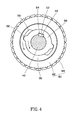
- the drive ring 50 When a rider pedals the pedals to rotate the crankshaft 40 forward, the drive ring 50 is rotated with the crankshaft 40 forward. During the forward rotation of the drive ring 50, the matching engagement between the protruding blocks 56 of the drive ring 50 and the mounting grooves 34 of the socket 32 of the chainwheel 30 causes the chainwheel 30 to be rotated forward, as shown in FIG. 4 , and therefore a chain can be driven by the chainwheel 30 to rotate the rear wheel forward. Further, when the drive ring 50 drives the socket 32 to rotate forward, the two magnet holders 62 and 72 are rotated with the socket 32 and the drive ring 50 synchronously.
- the motor 20 keeps providing the assisted power to the socket 32 of the chainwheel 30.
- the drive ring 50 When the rider pedals the pedals in the reversed direction to rotate the crankshaft 40 backward, the drive ring 50 is rotated with the crankshaft 40 backward, as shown in FIG. 5 .
- the protruding blocks 56 of the drive ring 50 do not touch the mounting grooves 34 of the socket 32, generating a time lag.
- the magnet holder 62 will be driven by the drive ring 50 to rotate relative to the other magnet holder 72, causing polar misalignment between the magnets 64 at the magnet holder 62 and the magnets 74 at the magnet holder 72, as shown in FIG. 6 .
- the magnetic sensors 80 sense the variation of the magnetic field and then interrupt the output of the motor 20.
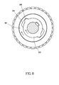
- the protruding blocks 56 of the drive ring 50 touch the mounting grooves 34 of the socket 32, and then drive the socket 32 and the chainwheel 30 to rotate backward, as shown in FIG. 8 .
- the chainwheel 30 starts reversing, it can pull the chain to produce a braking effect.
- the reverse brake mechanism 10 enables the crankshaft 40 to drive the electrically assisted bicycle forward during its forward rotation, and uses magnetic sensors 80 to sense polar misalignment between magnets 64 and 74 and to further interrupt the assisted power of the motor 20 during a backward rotation of the crankshaft 40 so that the crankshaft 40 can reverse the chainwheel 30 to produce a braking effect when it is rotated backward.
Landscapes
- Engineering & Computer Science (AREA)
- Mechanical Engineering (AREA)
- Chemical & Material Sciences (AREA)
- Combustion & Propulsion (AREA)
- Transportation (AREA)
- Dynamo-Electric Clutches, Dynamo-Electric Brakes (AREA)
Abstract
Description
- The present invention relates to an electrically assisted bicycle and more particularly, to a reverse brake mechanism for an electrically assisted bicycle.
- When a person rides a bicycle, the bicycle rider normally pedals the pedals with the legs to rotate the crankshaft forward, causing the crankshaft to rotate the chainwheel. At this time, the chainwheel causes the chain to rotate the rear wheel of the bicycle, driving the bicycle to run forward.
- When the bicycle rider wishes to stop the bicycle, the bicycle rider normally will pull the brake lever to drive the rear caliper, thereby stopping the rear wheel. However, to some bicycle riders, for example, children or the elderly, who have a lower than average grip strength, the conventional brake designs may be unable to achieve the expected effects, potentially increasing the risk of riding. Therefore, reverse brake designs are created to generate a braking effect upon reverse pedaling of the pedals. For example,
US4,261,449 "Bicycle pedal actuated brake control and release system" andUS5,810,139 "Bicycle and a friction device for controlling a clamping roller coupling of a bicycle hub of a bicycle" provide means to link a brake mechanism in the wheel hub to the chain during a reverse rotation of the cranks of the pedals, causing the brake mechanism to brake the rear wheel. However, these designs are to be used in regular bicycles, not applicable to electrically assisted bicycles. - Therefore, the inventor of the present invention creates a center mounted driving mechanism having a reverse pedal brake function for electrically assisted bicycle.
- The present invention has been accomplished under the circumstances in view. It is the main object of the present to provide a reverse brake mechanism for electrically assisted bicycle, which generates a time lag at the time the pedals are pedaled reversely, forming a time difference for allowing interruption of the output of the assisted power of the motor.
- To achieve this and other objects of the present invention, a reverse brake mechanism for electrically assisted bicycle in accordance with the present invention comprises a motor, a chainwheel, a crankshaft, a drive ring, two magnetic devices, and two magnetic sensors. The chainwheel comprises a socket coupled to the motor for one-way rotation and rotatable by the motor in the forward direction. The crankshaft is rotatably inserted through the socket of the chainwheel. The drive ring is fixedly mounted around the crankshaft and coupled to the socket of the chainwheel. Thus, the drive ring can be driven by the crankshaft to rotate the socket. Each magnetic device comprises a magnet holder and a magnet. The two magnet holders are respectively fixedly mounted at the socket of the chainwheel and the drive ring so that the two magnet holders can be respectively driven by the socket of the chainwheel and the drive ring to rotate synchronously or relative to each other. The magnets are respectively mounted in the two magnet holders corresponding to each other so that the magnets at the two magnet holders can be kept in a polar misalignment condition when the two magnet holders are rotated relative to each other. The magnetic sensors are electrically connected to the motor and disposed facing toward the magnets of the respective magnetic devices for sensing a polar misalignment between the magnets at the magnetic devices and interrupting the output of the assisted power of the motor. Thus, when the output of the assisted power of the motor is interrupted, the drive ring is continuously rotated with the crankshaft to reverse the chainwheel, achieving a braking effect.
- Other advantages and features of the present invention will be fully understood by reference to the following specification in conjunction with the accompanying drawings, in which like reference signs denote like components of structure.
-
-
FIG. 1 is a perspective view of a reverse brake mechanism for an electrically assisted bicycle in accordance with the present invention; -
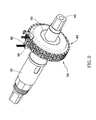
FIG. 2 is a perspective view of a part of the reverse brake mechanism for an electrically assisted bicycle in accordance with the present invention; -
FIG. 3 is an exploded view of the part of the reverse brake mechanism for an electrically assisted bicycle shown inFIG. 2 ; -
FIG. 4 is a sectional view of the present invention, illustrating the drive ring driven by the crankshaft and the socket rotated forward with the drive ring; -
FIG. 5 is a top view of a part of the present invention, illustrating the magnets of the two magnetic devices in polar alignment; -
FIG. 6 is similar toFIG. 4 , illustrating the drive ring rotated backward, the protruding blocks of the drive ring kept part from the mounting grooves of the socket. -
FIG. 7 is similar toFIG. 5 , illustrating the magnets of the two magnetic devices in polar misalignment; and -
FIG. 8 is similar toFIG. 6 , illustrating the socket rotated backward with the drive ring. - Referring to
FIGS. 1-3 , areverse brake mechanism 10 in accordance with the present invention is shown for use in an electrically assisted bicycle. Thereverse brake mechanism 10 comprises amotor 20, achainwheel 30, acrankshaft 40, adrive ring 50, twomagnetic devices magnetic sensors 80. - The
motor 20 is mounted at a frame of the electrically assisted bicycle to provide assisted power. Because themotor 20 is a well-known device, no further detailed description in this regard is necessary. - The
chainwheel 30 comprises asocket 32 coupled to themotor 20 through a one-way coupling (not shown), enabling thechainwheel 30 to be rotated in one direction by themotor 20 to output the assisted power of themotor 20. Further, thesocket 32 has twoopposite mounting grooves 34 in an inner perimeter thereof. - The
crankshaft 40 is inserted through thesocket 32 of thechainwheel 30, having two opposite ends respectively extended out of themotor 20 and connected with onerespective crank arm 90. Thus, thecrankshaft 40 can be driven by the twocrank arms 90 to rotate forward or backward. Further, thecrankshaft 40 has afirst key slot 42 in an outer periphery thereof. - The
drive ring 50 has asecond key slot 52 in the inner perimeter thereof, and twoopposite protruding blocks 56 at the outer perimeter thereof. Further, a key 54 is engaged in between the firstkey slot 42 of thecrankshaft 40 and thesecond key slot 52 of thedrive ring 50 to join thedrive ring 50 and thecrankshaft 40 together. The length of theprotruding blocks 56 is smaller than the length of themounting grooves 34. Further, theprotruding blocks 56 are respectively inserted into themounting grooves 34 in thesocket 32 of thechainwheel 30 so that thedrive ring 50 can be driven by thecrankshaft 40 to rotate thesocket 32 of thechainwheel 30 forward or backward. - The two
magnetic devices magnet holder magnets magnet holders socket 32 of thechainwheel 30 and thedrive ring 50. Themagnets magnet holders adjacent magnets 64 of themagnetic devices 60 have reversed polarity, and the twoadjacent magnets 74 of themagnetic devices 70 have reversed polarity, and further, themagnets 64 are respectively kept in alignment with themagnets 74 in a co-polarity manner. - The two
magnetic sensors 80 are fixedly mounted in asensor holder 82. Thesensor holder 82 is set between the twomagnet holders magnetic sensors 80 are electrically connected to themotor 20, and respectively disposed to face toward themagnets magnetic devices motor 20 subject to the detection results. Further, in this embodiment, themagnetic sensors 80 are Hall effect sensors. - After understanding of the structural details of the
reverse brake mechanism 10, the operation and features of thereverse brake mechanism 10 are outlined hereinafter. - When a rider pedals the pedals to rotate the
crankshaft 40 forward, thedrive ring 50 is rotated with thecrankshaft 40 forward. During the forward rotation of thedrive ring 50, the matching engagement between theprotruding blocks 56 of thedrive ring 50 and themounting grooves 34 of thesocket 32 of thechainwheel 30 causes thechainwheel 30 to be rotated forward, as shown inFIG. 4 , and therefore a chain can be driven by thechainwheel 30 to rotate the rear wheel forward. Further, when thedrive ring 50 drives thesocket 32 to rotate forward, the twomagnet holders socket 32 and thedrive ring 50 synchronously. At this time, themagnets magnetic devices FIG. 5 , and therefore, themotor 20 keeps providing the assisted power to thesocket 32 of thechainwheel 30. - When the rider pedals the pedals in the reversed direction to rotate the
crankshaft 40 backward, thedrive ring 50 is rotated with thecrankshaft 40 backward, as shown inFIG. 5 . At this moment, theprotruding blocks 56 of thedrive ring 50 do not touch themounting grooves 34 of thesocket 32, generating a time lag. In this time lag, themagnet holder 62 will be driven by thedrive ring 50 to rotate relative to theother magnet holder 72, causing polar misalignment between themagnets 64 at themagnet holder 62 and themagnets 74 at themagnet holder 72, as shown inFIG. 6 . At this time, themagnetic sensors 80 sense the variation of the magnetic field and then interrupt the output of themotor 20. Thereafter, the protruding blocks 56 of thedrive ring 50 touch the mountinggrooves 34 of thesocket 32, and then drive thesocket 32 and thechainwheel 30 to rotate backward, as shown inFIG. 8 . Once thechainwheel 30 starts reversing, it can pull the chain to produce a braking effect. - In conclusion, the
reverse brake mechanism 10 enables thecrankshaft 40 to drive the electrically assisted bicycle forward during its forward rotation, and usesmagnetic sensors 80 to sense polar misalignment betweenmagnets motor 20 during a backward rotation of thecrankshaft 40 so that thecrankshaft 40 can reverse thechainwheel 30 to produce a braking effect when it is rotated backward.
Claims (6)
- A reverse brake mechanism (10) for electrically assisted bicycle, comprising:a motor (20) for outputting an assisted power;a chainwheel (30) comprising a socket (32) coupled to said motor (20) for rotation in one direction and rotatable by said motor (20) in a forward direction;a crankshaft (40) rotatably inserted through said socket (32) of said chainwheel (30);a drive ring (50) fixedly mounted around said crankshaft (40) and coupled to said socket (32) of said chainwheel (30) in such a manner that when said crankshaft (40) is rotated forward, said drive ring (50) is driven by said crankshaft (40) to rotate said socket (32) and said chainwheel (30) forward; when said crankshaft (40) is rotated backward, said drive ring (50) is driven by said crankshaft (40) to rotate relative to said socket (32) and then to rotate said socket (32) and said chainwheel (30) backward after a predetermined time lag;two magnetic devices (60) and (70) each comprising a magnet holder and a magnet, said two magnet holders being respectively fixedly mounted at said socket (32) of said chainwheel (30) and said drive ring (50), the magnet of each said magnetic device being fixedly mounted in the associating said magnet holder in such a manner that when said crankshaft (40) is rotated forward, said two magnet holders are synchronously driven by said socket (32) of said chainwheel (30) and said drive ring (50) to rotate forward; when said crankshaft (40) is rotated backward, one said magnet holder is driven by said drive ring (50) to rotate relative to the other said magnet holder in said predetermined time lag, causing a polar misalignment between the magnet of one said magnetic device and the magnet of the other said magnetic device; andtwo magnetic sensors (80) electrically connected to said motor (20) and respectively facing toward the magnets of said two magnetic devices (60) and (70) for sensing the polar misalignment between the magnet of one said magnetic device and the magnet of the other said magnetic device and interrupting the output of the assisted power of said motor (20).
- The reverse brake mechanism (10 for electrically assisted bicycle as claimed in claim 1, wherein said socket (32 of said chainwheel (30 defines a mounting groove in an inner perimeter thereof; said drive ring (50 comprises a protruding block located at an outer perimeter thereof and insertable into said mounting groove of said socket (32, the length of each said protruding block being smaller than the length of each said mounting groove.
- The reverse brake mechanism (10) for electrically assisted bicycle as claimed in claim 1, wherein said crankshaft (40) defines a first key slot (42) in the periphery thereof; said drive ring (50) defines a second key slot (52) in an inner perimeter thereof; a key (54) is engaged in between said first key slot (42) and said second key slot (52) to join said crankshaft (40) and said drive ring (50) together.
- The reverse brake mechanism (10) for electrically assisted bicycle as claimed in claim 1, wherein the magnets of said two magnetic devices (60) and (70) have the same magnetism.
- The reverse brake mechanism (10) for electrically assisted bicycle as claimed in claim 1, wherein each said magnetic device comprises a plurality of magnets alternatively reversely arranged around the associating said magnet holder.
- The reverse brake mechanism (10) for electrically assisted bicycle as claimed in claim 1, wherein said two magnetic sensors (80) are fixedly mounted in a sensor holder (82) set between said two magnetic holders of said two magnetic devices (60) and (70).
Applications Claiming Priority (1)
| Application Number | Priority Date | Filing Date | Title |
|---|---|---|---|
| TW101117089A TW201345788A (en) | 2012-05-14 | 2012-05-14 | Reverse pedaling brake mechanism of power-assisted bicycle |
Publications (2)
| Publication Number | Publication Date |
|---|---|
| EP2664533A1 true EP2664533A1 (en) | 2013-11-20 |
| EP2664533B1 EP2664533B1 (en) | 2015-01-07 |
Family
ID=48463757
Family Applications (1)
| Application Number | Title | Priority Date | Filing Date |
|---|---|---|---|
| EP13167677.7A Active EP2664533B1 (en) | 2012-05-14 | 2013-05-14 | Reverse brake mechanism for electrically assisted bicycle |
Country Status (3)
| Country | Link |
|---|---|
| EP (1) | EP2664533B1 (en) |
| DK (1) | DK2664533T3 (en) |
| TW (1) | TW201345788A (en) |
Cited By (6)
| Publication number | Priority date | Publication date | Assignee | Title |
|---|---|---|---|---|
| CN107406120A (en) * | 2015-02-10 | 2017-11-28 | 台风自行车有限公司 | Dual motor power unit and method of mounting the unit to a bicycle frame |
| CN107651094A (en) * | 2016-11-07 | 2018-02-02 | 太仓市悦博电动科技有限公司 | In put the separator of falling brake and electric bicycle of electric bicycle |
| DE102019105757B3 (en) * | 2019-03-07 | 2020-04-23 | Schaeffler Technologies AG & Co. KG | Muscle-powered vehicle and method for regulating the recuperation power of such a vehicle |
| CN112141254A (en) * | 2020-10-20 | 2020-12-29 | 刘功平 | Hub inner side driving easy-to-dismount seat cushion quick-drop folding bicycle or electric bicycle |
| GB2613888A (en) * | 2021-12-20 | 2023-06-21 | Anthony Connell Richard | A crank assembly |
| DE102019117299B4 (en) | 2018-06-29 | 2026-03-26 | Shimano Inc. | DRIVE DEVICE OF A HUMAN-POWERED VEHICLE |
Citations (7)
| Publication number | Priority date | Publication date | Assignee | Title |
|---|---|---|---|---|
| US4261449A (en) | 1978-08-28 | 1981-04-14 | Foster Edwin E | Bicycle pedal actuated brake control and release system |
| US5810139A (en) | 1996-05-03 | 1998-09-22 | Mannesmann Sachs Ag | Bicycle and a friction device for controlling a clamping roller coupling of a bicycle hub of a bicycle |
| US5900703A (en) * | 1996-02-07 | 1999-05-04 | Li; Tsan Kuang | Motor control system of electrical-motorized bicycle |
| DE202009014577U1 (en) * | 2009-10-28 | 2011-03-10 | Daum Gmbh & Co. Kg | Resignation brake |
| EP2380806A2 (en) * | 2010-04-21 | 2011-10-26 | Daum GmbH & Co. KG | Power transmission unit |
| EP2384962A1 (en) * | 2010-05-06 | 2011-11-09 | Robert Bosch GmbH | Back-pedal drive for electric bicycles and method for controlled coupling of the drive and motor of an electric bicycle |
| DE102010028645A1 (en) * | 2010-05-06 | 2011-11-10 | Robert Bosch Gmbh | Method for operation of electric brake of electric bicycle, involves detecting drive torque and rotational speed of pedal drive of electric bicycle, where braking torque is generated via electric brake |
-
2012
- 2012-05-14 TW TW101117089A patent/TW201345788A/en unknown
-
2013
- 2013-05-14 EP EP13167677.7A patent/EP2664533B1/en active Active
- 2013-05-14 DK DK13167677.7T patent/DK2664533T3/en active
Patent Citations (7)
| Publication number | Priority date | Publication date | Assignee | Title |
|---|---|---|---|---|
| US4261449A (en) | 1978-08-28 | 1981-04-14 | Foster Edwin E | Bicycle pedal actuated brake control and release system |
| US5900703A (en) * | 1996-02-07 | 1999-05-04 | Li; Tsan Kuang | Motor control system of electrical-motorized bicycle |
| US5810139A (en) | 1996-05-03 | 1998-09-22 | Mannesmann Sachs Ag | Bicycle and a friction device for controlling a clamping roller coupling of a bicycle hub of a bicycle |
| DE202009014577U1 (en) * | 2009-10-28 | 2011-03-10 | Daum Gmbh & Co. Kg | Resignation brake |
| EP2380806A2 (en) * | 2010-04-21 | 2011-10-26 | Daum GmbH & Co. KG | Power transmission unit |
| EP2384962A1 (en) * | 2010-05-06 | 2011-11-09 | Robert Bosch GmbH | Back-pedal drive for electric bicycles and method for controlled coupling of the drive and motor of an electric bicycle |
| DE102010028645A1 (en) * | 2010-05-06 | 2011-11-10 | Robert Bosch Gmbh | Method for operation of electric brake of electric bicycle, involves detecting drive torque and rotational speed of pedal drive of electric bicycle, where braking torque is generated via electric brake |
Cited By (8)
| Publication number | Priority date | Publication date | Assignee | Title |
|---|---|---|---|---|
| CN107406120A (en) * | 2015-02-10 | 2017-11-28 | 台风自行车有限公司 | Dual motor power unit and method of mounting the unit to a bicycle frame |
| CN107406120B (en) * | 2015-02-10 | 2019-12-03 | S·C·P·台风 | Dual motor power unit and method of mounting the unit to a bicycle frame |
| CN107651094A (en) * | 2016-11-07 | 2018-02-02 | 太仓市悦博电动科技有限公司 | In put the separator of falling brake and electric bicycle of electric bicycle |
| DE102019117299B4 (en) | 2018-06-29 | 2026-03-26 | Shimano Inc. | DRIVE DEVICE OF A HUMAN-POWERED VEHICLE |
| DE102019105757B3 (en) * | 2019-03-07 | 2020-04-23 | Schaeffler Technologies AG & Co. KG | Muscle-powered vehicle and method for regulating the recuperation power of such a vehicle |
| CN112141254A (en) * | 2020-10-20 | 2020-12-29 | 刘功平 | Hub inner side driving easy-to-dismount seat cushion quick-drop folding bicycle or electric bicycle |
| GB2613888A (en) * | 2021-12-20 | 2023-06-21 | Anthony Connell Richard | A crank assembly |
| GB2613888B (en) * | 2021-12-20 | 2024-03-20 | Anthony Connell Richard | A crank assembly |
Also Published As
| Publication number | Publication date |
|---|---|
| EP2664533B1 (en) | 2015-01-07 |
| TW201345788A (en) | 2013-11-16 |
| DK2664533T3 (en) | 2015-04-20 |
| TWI440578B (en) | 2014-06-11 |
Similar Documents
| Publication | Publication Date | Title |
|---|---|---|
| EP2664533A1 (en) | Reverse brake mechanism for electrically assisted bicycle | |
| TWI552916B (en) | Electric bicycle and control method thereof | |
| TWI673198B (en) | Bicycle device | |
| US10167053B2 (en) | Bicycle drive unit | |
| TWI532627B (en) | Bicycle suspension | |
| JP6226115B2 (en) | Electric assist bicycle | |
| WO2012136143A1 (en) | Electric-assisted bike torque sensor | |
| TWI635022B (en) | Clutch bicycle electric drive | |
| US8869652B2 (en) | Power assisting transmission system of power assisting bike | |
| EP2910462A1 (en) | Center-mounted motor | |
| US11052961B2 (en) | Selectable motor clutch, system, and method | |
| CN104773254A (en) | Driving assembly of electric bicycle | |
| CN202593771U (en) | Reverse braking mechanism of electric bicycle | |
| CN103373434B (en) | Reversing Brake Mechanism of Electric Assisted Bicycle | |
| CN204184541U (en) | A kind of conducting slip ring for Electrical Bicycle | |
| WO2018082144A1 (en) | Reverse braking disengagement device for mid-drive motor type electric bicycle | |
| CN202807012U (en) | Reverse braking mechanism of electric bicycle | |
| CN102658849B (en) | Reverse rotation brake mechanism of electric bicycle | |
| JP7126139B2 (en) | Electric bicycle and its control method | |
| CN102765456B (en) | Reverse-stepping brake mechanism of electric bicycle | |
| CN104002916A (en) | Double magnetic ring rear pedal assist interruption system for electric assist bicycle | |
| CN104169164A (en) | Speedy wheel | |
| CN103419881B (en) | Reverse Braking Mechanism of Electric Assisted Bicycle | |
| TW201341225A (en) | Reverse braking mechanism of power-assisted bicycle | |
| TW201741190A (en) | A bicycle drive unit |
Legal Events
| Date | Code | Title | Description |
|---|---|---|---|
| PUAI | Public reference made under article 153(3) epc to a published international application that has entered the european phase |
Free format text: ORIGINAL CODE: 0009012 |
|
| 17P | Request for examination filed |
Effective date: 20130514 |
|
| AK | Designated contracting states |
Kind code of ref document: A1 Designated state(s): AL AT BE BG CH CY CZ DE DK EE ES FI FR GB GR HR HU IE IS IT LI LT LU LV MC MK MT NL NO PL PT RO RS SE SI SK SM TR |
|
| AX | Request for extension of the european patent |
Extension state: BA ME |
|
| GRAP | Despatch of communication of intention to grant a patent |
Free format text: ORIGINAL CODE: EPIDOSNIGR1 |
|
| RIC1 | Information provided on ipc code assigned before grant |
Ipc: B62L 5/00 20060101AFI20140616BHEP Ipc: B62M 6/45 20100101ALI20140616BHEP Ipc: B62M 6/55 20100101ALI20140616BHEP Ipc: G01L 3/10 20060101ALI20140616BHEP |
|
| INTG | Intention to grant announced |
Effective date: 20140715 |
|
| GRAS | Grant fee paid |
Free format text: ORIGINAL CODE: EPIDOSNIGR3 |
|
| GRAA | (expected) grant |
Free format text: ORIGINAL CODE: 0009210 |
|
| AK | Designated contracting states |
Kind code of ref document: B1 Designated state(s): AL AT BE BG CH CY CZ DE DK EE ES FI FR GB GR HR HU IE IS IT LI LT LU LV MC MK MT NL NO PL PT RO RS SE SI SK SM TR |
|
| REG | Reference to a national code |
Ref country code: GB Ref legal event code: FG4D |
|
| REG | Reference to a national code |
Ref country code: CH Ref legal event code: EP |
|
| REG | Reference to a national code |
Ref country code: IE Ref legal event code: FG4D |
|
| REG | Reference to a national code |
Ref country code: AT Ref legal event code: REF Ref document number: 705485 Country of ref document: AT Kind code of ref document: T Effective date: 20150215 |
|
| REG | Reference to a national code |
Ref country code: DE Ref legal event code: R096 Ref document number: 602013000783 Country of ref document: DE Effective date: 20150226 |
|
| REG | Reference to a national code |
Ref country code: DK Ref legal event code: T3 Effective date: 20150413 |
|
| REG | Reference to a national code |
Ref country code: NL Ref legal event code: VDEP Effective date: 20150107 |
|
| REG | Reference to a national code |
Ref country code: AT Ref legal event code: MK05 Ref document number: 705485 Country of ref document: AT Kind code of ref document: T Effective date: 20150107 |
|
| REG | Reference to a national code |
Ref country code: LT Ref legal event code: MG4D |
|
| PG25 | Lapsed in a contracting state [announced via postgrant information from national office to epo] |
Ref country code: ES Free format text: LAPSE BECAUSE OF FAILURE TO SUBMIT A TRANSLATION OF THE DESCRIPTION OR TO PAY THE FEE WITHIN THE PRESCRIBED TIME-LIMIT Effective date: 20150107 Ref country code: FI Free format text: LAPSE BECAUSE OF FAILURE TO SUBMIT A TRANSLATION OF THE DESCRIPTION OR TO PAY THE FEE WITHIN THE PRESCRIBED TIME-LIMIT Effective date: 20150107 Ref country code: LT Free format text: LAPSE BECAUSE OF FAILURE TO SUBMIT A TRANSLATION OF THE DESCRIPTION OR TO PAY THE FEE WITHIN THE PRESCRIBED TIME-LIMIT Effective date: 20150107 Ref country code: NO Free format text: LAPSE BECAUSE OF FAILURE TO SUBMIT A TRANSLATION OF THE DESCRIPTION OR TO PAY THE FEE WITHIN THE PRESCRIBED TIME-LIMIT Effective date: 20150407 Ref country code: SE Free format text: LAPSE BECAUSE OF FAILURE TO SUBMIT A TRANSLATION OF THE DESCRIPTION OR TO PAY THE FEE WITHIN THE PRESCRIBED TIME-LIMIT Effective date: 20150107 Ref country code: BG Free format text: LAPSE BECAUSE OF FAILURE TO SUBMIT A TRANSLATION OF THE DESCRIPTION OR TO PAY THE FEE WITHIN THE PRESCRIBED TIME-LIMIT Effective date: 20150407 Ref country code: HR Free format text: LAPSE BECAUSE OF FAILURE TO SUBMIT A TRANSLATION OF THE DESCRIPTION OR TO PAY THE FEE WITHIN THE PRESCRIBED TIME-LIMIT Effective date: 20150107 |
|
| PG25 | Lapsed in a contracting state [announced via postgrant information from national office to epo] |
Ref country code: RS Free format text: LAPSE BECAUSE OF FAILURE TO SUBMIT A TRANSLATION OF THE DESCRIPTION OR TO PAY THE FEE WITHIN THE PRESCRIBED TIME-LIMIT Effective date: 20150107 Ref country code: NL Free format text: LAPSE BECAUSE OF FAILURE TO SUBMIT A TRANSLATION OF THE DESCRIPTION OR TO PAY THE FEE WITHIN THE PRESCRIBED TIME-LIMIT Effective date: 20150107 Ref country code: LV Free format text: LAPSE BECAUSE OF FAILURE TO SUBMIT A TRANSLATION OF THE DESCRIPTION OR TO PAY THE FEE WITHIN THE PRESCRIBED TIME-LIMIT Effective date: 20150107 Ref country code: AT Free format text: LAPSE BECAUSE OF FAILURE TO SUBMIT A TRANSLATION OF THE DESCRIPTION OR TO PAY THE FEE WITHIN THE PRESCRIBED TIME-LIMIT Effective date: 20150107 Ref country code: GR Free format text: LAPSE BECAUSE OF FAILURE TO SUBMIT A TRANSLATION OF THE DESCRIPTION OR TO PAY THE FEE WITHIN THE PRESCRIBED TIME-LIMIT Effective date: 20150408 Ref country code: IS Free format text: LAPSE BECAUSE OF FAILURE TO SUBMIT A TRANSLATION OF THE DESCRIPTION OR TO PAY THE FEE WITHIN THE PRESCRIBED TIME-LIMIT Effective date: 20150507 Ref country code: PL Free format text: LAPSE BECAUSE OF FAILURE TO SUBMIT A TRANSLATION OF THE DESCRIPTION OR TO PAY THE FEE WITHIN THE PRESCRIBED TIME-LIMIT Effective date: 20150107 |
|
| REG | Reference to a national code |
Ref country code: DE Ref legal event code: R097 Ref document number: 602013000783 Country of ref document: DE |
|
| PG25 | Lapsed in a contracting state [announced via postgrant information from national office to epo] |
Ref country code: EE Free format text: LAPSE BECAUSE OF FAILURE TO SUBMIT A TRANSLATION OF THE DESCRIPTION OR TO PAY THE FEE WITHIN THE PRESCRIBED TIME-LIMIT Effective date: 20150107 Ref country code: CZ Free format text: LAPSE BECAUSE OF FAILURE TO SUBMIT A TRANSLATION OF THE DESCRIPTION OR TO PAY THE FEE WITHIN THE PRESCRIBED TIME-LIMIT Effective date: 20150107 Ref country code: SK Free format text: LAPSE BECAUSE OF FAILURE TO SUBMIT A TRANSLATION OF THE DESCRIPTION OR TO PAY THE FEE WITHIN THE PRESCRIBED TIME-LIMIT Effective date: 20150107 Ref country code: RO Free format text: LAPSE BECAUSE OF FAILURE TO SUBMIT A TRANSLATION OF THE DESCRIPTION OR TO PAY THE FEE WITHIN THE PRESCRIBED TIME-LIMIT Effective date: 20150107 |
|
| PLBE | No opposition filed within time limit |
Free format text: ORIGINAL CODE: 0009261 |
|
| STAA | Information on the status of an ep patent application or granted ep patent |
Free format text: STATUS: NO OPPOSITION FILED WITHIN TIME LIMIT |
|
| 26N | No opposition filed |
Effective date: 20151008 |
|
| PG25 | Lapsed in a contracting state [announced via postgrant information from national office to epo] |
Ref country code: IT Free format text: LAPSE BECAUSE OF FAILURE TO SUBMIT A TRANSLATION OF THE DESCRIPTION OR TO PAY THE FEE WITHIN THE PRESCRIBED TIME-LIMIT Effective date: 20150107 |
|
| PG25 | Lapsed in a contracting state [announced via postgrant information from national office to epo] |
Ref country code: LU Free format text: LAPSE BECAUSE OF FAILURE TO SUBMIT A TRANSLATION OF THE DESCRIPTION OR TO PAY THE FEE WITHIN THE PRESCRIBED TIME-LIMIT Effective date: 20150514 Ref country code: MC Free format text: LAPSE BECAUSE OF FAILURE TO SUBMIT A TRANSLATION OF THE DESCRIPTION OR TO PAY THE FEE WITHIN THE PRESCRIBED TIME-LIMIT Effective date: 20150107 |
|
| REG | Reference to a national code |
Ref country code: IE Ref legal event code: MM4A |
|
| REG | Reference to a national code |
Ref country code: FR Ref legal event code: ST Effective date: 20160129 |
|
| PG25 | Lapsed in a contracting state [announced via postgrant information from national office to epo] |
Ref country code: SI Free format text: LAPSE BECAUSE OF FAILURE TO SUBMIT A TRANSLATION OF THE DESCRIPTION OR TO PAY THE FEE WITHIN THE PRESCRIBED TIME-LIMIT Effective date: 20150107 |
|
| PG25 | Lapsed in a contracting state [announced via postgrant information from national office to epo] |
Ref country code: IE Free format text: LAPSE BECAUSE OF NON-PAYMENT OF DUE FEES Effective date: 20150514 |
|
| PG25 | Lapsed in a contracting state [announced via postgrant information from national office to epo] |
Ref country code: FR Free format text: LAPSE BECAUSE OF NON-PAYMENT OF DUE FEES Effective date: 20150601 Ref country code: BE Free format text: LAPSE BECAUSE OF FAILURE TO SUBMIT A TRANSLATION OF THE DESCRIPTION OR TO PAY THE FEE WITHIN THE PRESCRIBED TIME-LIMIT Effective date: 20150107 |
|
| PGFP | Annual fee paid to national office [announced via postgrant information from national office to epo] |
Ref country code: DK Payment date: 20160523 Year of fee payment: 4 |
|
| PG25 | Lapsed in a contracting state [announced via postgrant information from national office to epo] |
Ref country code: MT Free format text: LAPSE BECAUSE OF FAILURE TO SUBMIT A TRANSLATION OF THE DESCRIPTION OR TO PAY THE FEE WITHIN THE PRESCRIBED TIME-LIMIT Effective date: 20150107 |
|
| REG | Reference to a national code |
Ref country code: CH Ref legal event code: PL |
|
| PG25 | Lapsed in a contracting state [announced via postgrant information from national office to epo] |
Ref country code: CH Free format text: LAPSE BECAUSE OF NON-PAYMENT OF DUE FEES Effective date: 20160531 Ref country code: LI Free format text: LAPSE BECAUSE OF NON-PAYMENT OF DUE FEES Effective date: 20160531 |
|
| PG25 | Lapsed in a contracting state [announced via postgrant information from national office to epo] |
Ref country code: HU Free format text: LAPSE BECAUSE OF FAILURE TO SUBMIT A TRANSLATION OF THE DESCRIPTION OR TO PAY THE FEE WITHIN THE PRESCRIBED TIME-LIMIT; INVALID AB INITIO Effective date: 20130514 |
|
| PG25 | Lapsed in a contracting state [announced via postgrant information from national office to epo] |
Ref country code: CY Free format text: LAPSE BECAUSE OF FAILURE TO SUBMIT A TRANSLATION OF THE DESCRIPTION OR TO PAY THE FEE WITHIN THE PRESCRIBED TIME-LIMIT Effective date: 20150107 |
|
| PG25 | Lapsed in a contracting state [announced via postgrant information from national office to epo] |
Ref country code: TR Free format text: LAPSE BECAUSE OF FAILURE TO SUBMIT A TRANSLATION OF THE DESCRIPTION OR TO PAY THE FEE WITHIN THE PRESCRIBED TIME-LIMIT Effective date: 20150107 |
|
| REG | Reference to a national code |
Ref country code: DK Ref legal event code: EBP Effective date: 20170531 |
|
| GBPC | Gb: european patent ceased through non-payment of renewal fee |
Effective date: 20170514 |
|
| PG25 | Lapsed in a contracting state [announced via postgrant information from national office to epo] |
Ref country code: DK Free format text: LAPSE BECAUSE OF NON-PAYMENT OF DUE FEES Effective date: 20170531 Ref country code: GB Free format text: LAPSE BECAUSE OF NON-PAYMENT OF DUE FEES Effective date: 20170514 |
|
| PG25 | Lapsed in a contracting state [announced via postgrant information from national office to epo] |
Ref country code: SM Free format text: LAPSE BECAUSE OF FAILURE TO SUBMIT A TRANSLATION OF THE DESCRIPTION OR TO PAY THE FEE WITHIN THE PRESCRIBED TIME-LIMIT Effective date: 20150107 |
|
| PG25 | Lapsed in a contracting state [announced via postgrant information from national office to epo] |
Ref country code: MK Free format text: LAPSE BECAUSE OF FAILURE TO SUBMIT A TRANSLATION OF THE DESCRIPTION OR TO PAY THE FEE WITHIN THE PRESCRIBED TIME-LIMIT Effective date: 20150107 Ref country code: PT Free format text: LAPSE BECAUSE OF FAILURE TO SUBMIT A TRANSLATION OF THE DESCRIPTION OR TO PAY THE FEE WITHIN THE PRESCRIBED TIME-LIMIT Effective date: 20150107 |
|
| PG25 | Lapsed in a contracting state [announced via postgrant information from national office to epo] |
Ref country code: AL Free format text: LAPSE BECAUSE OF FAILURE TO SUBMIT A TRANSLATION OF THE DESCRIPTION OR TO PAY THE FEE WITHIN THE PRESCRIBED TIME-LIMIT Effective date: 20150107 |
|
| REG | Reference to a national code |
Ref country code: DE Ref legal event code: R082 Ref document number: 602013000783 Country of ref document: DE Representative=s name: STRAUS, ALEXANDER, DIPL.-CHEM.UNIV. DR.PHIL., DE Ref country code: DE Ref legal event code: R082 Ref document number: 602013000783 Country of ref document: DE Representative=s name: 2K PATENT- UND RECHTSANWAELTE PARTNERSCHAFT MB, DE |
|
| REG | Reference to a national code |
Ref country code: DE Ref legal event code: R082 Ref document number: 602013000783 Country of ref document: DE Representative=s name: STRAUS, ALEXANDER, DIPL.-CHEM.UNIV. DR.PHIL., DE |
|
| PGFP | Annual fee paid to national office [announced via postgrant information from national office to epo] |
Ref country code: DE Payment date: 20250528 Year of fee payment: 13 |