EP2664529A1 - Inverted pendulum type vehicle - Google Patents
Inverted pendulum type vehicle Download PDFInfo
- Publication number
- EP2664529A1 EP2664529A1 EP13167289.1A EP13167289A EP2664529A1 EP 2664529 A1 EP2664529 A1 EP 2664529A1 EP 13167289 A EP13167289 A EP 13167289A EP 2664529 A1 EP2664529 A1 EP 2664529A1
- Authority
- EP
- European Patent Office
- Prior art keywords
- driving
- vehicle body
- inverted pendulum
- pendulum type
- driving unit
- Prior art date
- Legal status (The legal status is an assumption and is not a legal conclusion. Google has not performed a legal analysis and makes no representation as to the accuracy of the status listed.)
- Granted
Links
- 230000005540 biological transmission Effects 0.000 claims abstract description 20
- 230000009467 reduction Effects 0.000 claims description 87
- 230000000149 penetrating effect Effects 0.000 claims description 15
- 230000007246 mechanism Effects 0.000 claims description 11
- 230000033001 locomotion Effects 0.000 description 29
- 230000002093 peripheral effect Effects 0.000 description 12
- 230000005484 gravity Effects 0.000 description 9
- 238000000034 method Methods 0.000 description 8
- 230000008569 process Effects 0.000 description 7
- 230000004044 response Effects 0.000 description 6
- 229920001971 elastomer Polymers 0.000 description 4
- 229910052751 metal Inorganic materials 0.000 description 4
- 239000002184 metal Substances 0.000 description 4
- 230000007935 neutral effect Effects 0.000 description 4
- 230000002787 reinforcement Effects 0.000 description 4
- 230000003466 anti-cipated effect Effects 0.000 description 3
- 238000013459 approach Methods 0.000 description 3
- 238000005452 bending Methods 0.000 description 2
- 230000008859 change Effects 0.000 description 2
- 238000004891 communication Methods 0.000 description 2
- 230000000994 depressogenic effect Effects 0.000 description 2
- 230000004048 modification Effects 0.000 description 2
- 238000012986 modification Methods 0.000 description 2
- 229910000831 Steel Inorganic materials 0.000 description 1
- 229910052782 aluminium Inorganic materials 0.000 description 1
- XAGFODPZIPBFFR-UHFFFAOYSA-N aluminium Chemical compound [Al] XAGFODPZIPBFFR-UHFFFAOYSA-N 0.000 description 1
- 230000000712 assembly Effects 0.000 description 1
- 238000000429 assembly Methods 0.000 description 1
- 230000004323 axial length Effects 0.000 description 1
- 230000015572 biosynthetic process Effects 0.000 description 1
- 238000012790 confirmation Methods 0.000 description 1
- 238000001816 cooling Methods 0.000 description 1
- 239000000428 dust Substances 0.000 description 1
- 230000000694 effects Effects 0.000 description 1
- 230000002452 interceptive effect Effects 0.000 description 1
- 239000010687 lubricating oil Substances 0.000 description 1
- 238000012423 maintenance Methods 0.000 description 1
- 239000000463 material Substances 0.000 description 1
- 229920002635 polyurethane Polymers 0.000 description 1
- 239000004814 polyurethane Substances 0.000 description 1
- 229920005989 resin Polymers 0.000 description 1
- 239000011347 resin Substances 0.000 description 1
- 239000007779 soft material Substances 0.000 description 1
- 239000010959 steel Substances 0.000 description 1
- 229920003002 synthetic resin Polymers 0.000 description 1
- 239000000057 synthetic resin Substances 0.000 description 1
- 239000004636 vulcanized rubber Substances 0.000 description 1
- 238000003466 welding Methods 0.000 description 1
Images


Classifications
-
- B—PERFORMING OPERATIONS; TRANSPORTING
- B62—LAND VEHICLES FOR TRAVELLING OTHERWISE THAN ON RAILS
- B62K—CYCLES; CYCLE FRAMES; CYCLE STEERING DEVICES; RIDER-OPERATED TERMINAL CONTROLS SPECIALLY ADAPTED FOR CYCLES; CYCLE AXLE SUSPENSIONS; CYCLE SIDE-CARS, FORECARS, OR THE LIKE
- B62K17/00—Cycles not otherwise provided for
-
- B—PERFORMING OPERATIONS; TRANSPORTING
- B62—LAND VEHICLES FOR TRAVELLING OTHERWISE THAN ON RAILS
- B62K—CYCLES; CYCLE FRAMES; CYCLE STEERING DEVICES; RIDER-OPERATED TERMINAL CONTROLS SPECIALLY ADAPTED FOR CYCLES; CYCLE AXLE SUSPENSIONS; CYCLE SIDE-CARS, FORECARS, OR THE LIKE
- B62K11/00—Motorcycles, engine-assisted cycles or motor scooters with one or two wheels
- B62K11/007—Automatic balancing machines with single main ground engaging wheel or coaxial wheels supporting a rider
-
- B—PERFORMING OPERATIONS; TRANSPORTING
- B62—LAND VEHICLES FOR TRAVELLING OTHERWISE THAN ON RAILS
- B62H—CYCLE STANDS; SUPPORTS OR HOLDERS FOR PARKING OR STORING CYCLES; APPLIANCES PREVENTING OR INDICATING UNAUTHORIZED USE OR THEFT OF CYCLES; LOCKS INTEGRAL WITH CYCLES; DEVICES FOR LEARNING TO RIDE CYCLES
- B62H1/00—Supports or stands forming part of or attached to cycles
- B62H1/10—Supports or stands forming part of or attached to cycles involving means providing for a stabilised ride
- B62H1/12—Supports or stands forming part of or attached to cycles involving means providing for a stabilised ride using additional wheels
-
- B—PERFORMING OPERATIONS; TRANSPORTING
- B62—LAND VEHICLES FOR TRAVELLING OTHERWISE THAN ON RAILS
- B62K—CYCLES; CYCLE FRAMES; CYCLE STEERING DEVICES; RIDER-OPERATED TERMINAL CONTROLS SPECIALLY ADAPTED FOR CYCLES; CYCLE AXLE SUSPENSIONS; CYCLE SIDE-CARS, FORECARS, OR THE LIKE
- B62K1/00—Unicycles
-
- B—PERFORMING OPERATIONS; TRANSPORTING
- B62—LAND VEHICLES FOR TRAVELLING OTHERWISE THAN ON RAILS
- B62K—CYCLES; CYCLE FRAMES; CYCLE STEERING DEVICES; RIDER-OPERATED TERMINAL CONTROLS SPECIALLY ADAPTED FOR CYCLES; CYCLE AXLE SUSPENSIONS; CYCLE SIDE-CARS, FORECARS, OR THE LIKE
- B62K11/00—Motorcycles, engine-assisted cycles or motor scooters with one or two wheels
- B62K11/02—Frames
-
- B—PERFORMING OPERATIONS; TRANSPORTING
- B62—LAND VEHICLES FOR TRAVELLING OTHERWISE THAN ON RAILS
- B62M—RIDER PROPULSION OF WHEELED VEHICLES OR SLEDGES; POWERED PROPULSION OF SLEDGES OR SINGLE-TRACK CYCLES; TRANSMISSIONS SPECIALLY ADAPTED FOR SUCH VEHICLES
- B62M7/00—Motorcycles characterised by position of motor or engine
- B62M7/02—Motorcycles characterised by position of motor or engine with engine between front and rear wheels
- B62M7/06—Motorcycles characterised by position of motor or engine with engine between front and rear wheels directly under the saddle or seat
-
- B—PERFORMING OPERATIONS; TRANSPORTING
- B60—VEHICLES IN GENERAL
- B60B—VEHICLE WHEELS; CASTORS; AXLES FOR WHEELS OR CASTORS; INCREASING WHEEL ADHESION
- B60B19/00—Wheels not otherwise provided for or having characteristics specified in one of the subgroups of this group
- B60B19/003—Multidirectional wheels
-
- B—PERFORMING OPERATIONS; TRANSPORTING
- B60—VEHICLES IN GENERAL
- B60B—VEHICLE WHEELS; CASTORS; AXLES FOR WHEELS OR CASTORS; INCREASING WHEEL ADHESION
- B60B19/00—Wheels not otherwise provided for or having characteristics specified in one of the subgroups of this group
- B60B19/12—Roller-type wheels
Abstract
Description
- The present invention claims priority under 35 USC 119 based on Japanese patent applications Nos.
2012-111054, filed on May 14, 2012 2012-111059, filed on May 14, 2012 - The present invention relates to an inverted pendulum type vehicle, and more particularly to an inverted pendulum type vehicle wherein left and right driving disks disposed at the opposite left and right ends of a main wheel are driven to rotate by corresponding individual driving units.
- Conventionally, as an inverted pendulum type vehicle, for example, an inverted pendulum type vehicle is known which includes a vehicle body frame, a main wheel, a pair of left and right driving disks, and driving units (see, for example, Japanese Patent Laid-Open No.
2010-247640 2011-63242 - The driving units include a left side driving unit for driving the left side driving disk, and a separate right side driving unit for driving the right side driving disk. Each of the left and right side driving units includes a driving motor attached to the vehicle body frame at a position above the main wheel, and a driving pulley attached to an output power shaft of the electric motor. Each of the left and right side driving units further includes a driven pulley attached to a corresponding one of the left and right driving disks, and an endless transmission belt extending between and around the mutually corresponding driving pulley and driven pulley.
- It is demanded to increase the driving torque of the driving disks in order to improve the traveling performance of the inverted pendulum type vehicle. As a countermeasure for increasing the driving torque, it seems recommendable to use an electric motor of an increased size to use increased output torque of the driving motor or to raise the reduction ratio between the electric motor and the driving disks.
- However, in a conventional inverted pendulum type vehicle, the electric motor of the left side driving unit and the electric motor of the right side driving unit are disposed in a juxtaposed relationship with each other in a vehicle body widthwise direction at the same height on the vehicle. Therefore, increase of the size of the electric motor is restricted by a space, and in order to use an electric motor of an increased size, it is necessary to increase the vehicle body width. Further, in a power transmission mechanism configured from a driving pulley, a driven pulley and an endless transmission belt, the reduction ratio depends upon the pulley size ratio between the driving pulley and the driven pulley, and there is a limitation to increase of the reduction ratio.
- In contrast, it seems recommendable to add a new gear type reduction gear to the electric motor. However, it is difficult in terms of the space to add a new reduction gear to the electric motor, and it is necessary to increase the size of the vehicle body.
- Further, if it is attempted to prepare a plurality of types of inverted pendulum type vehicles having output torque different depending upon the physique of the occupant such as a model on which a small person is to ride or another model on which a large person is to ride, then the conventional inverted pendulum type vehicle is not suitable. In particular, in the conventional inverted pendulum type vehicle, the electric motor of the left side driving unit and the electric motor of the right side driving unit are disposed in a juxtaposed and aligned relationship with each other in the vehicle body widthwise direction at the same height on the vehicle, as described above. Therefore, a space necessary for the change to an electric motor of different output torque, particularly, a space in the vehicle body widthwise direction, cannot be assured. Consequently, a plurality of inverted pendulum type vehicles of different vehicle classifications must be prepared, wherein the vehicle body frame is changed in response to the output torque of the electric motor.
- An object of the present invention is to make it possible to increase the output torque of driving disks while retaining a compact vehicle body configuration, without changing the vehicle classification.
- Another object of the present invention is to apply appropriate initial tension to an endless transmission belt used in a driving unit of an inverted pendulum type vehicle.
- Throughout the present specification, reference numbers are used to refer to the exemplary structures shown in the drawings, and such numbers are intended to illustrate, rather than to limit the invention.
- According to a first aspect of the present invention, there is provided an inverted pendulum type vehicle including: a vehicle body frame (10);a main wheel (52) formed by combining a plurality of rotatable driven rollers (64) such that axial lines of rotation of the driven rollers (64) form a ring; left and right driving disks (58) supported for rotation on the vehicle body frame (10) in such a manner as to be positioned on the left and right sides of the vehicle body frame (10) in a substantially coaxial relationship with an axial line of rotation of the main wheel (52) and each including a plurality of rotatable driving rollers (66) disposed for contact in a twisted relationship with the driven rollers (64).
- The vehicle also includes left and right driven pulleys (60) provided coaxially on the vehicle body outer sides of the driving disks (58); driving units (90, 130) attached to the vehicle body frame (10) above the main wheel (52) and having output power shafts (98, 138) to which driving pulleys (100, 140) are attached; and endless transmission members (122, 144) extending between and around mutually corresponding ones of the driving pulleys and the driven pulleys (60), wherein the left and right driving units (90, 130) are disposed in an vertically offset relationship from each other.
- According to a second aspect of the present invention, there is provided an inverted pendulum type vehicle wherein the left and right driving units (90, 130) overlap at least at part thereof with each other as viewed in plan.
- According to a third aspect of the present invention, there is provided an inverted pendulum type vehicle wherein each of the driving units (90, 130) has an electric motor (84, 132), a reduction gear (96, 136) disposed between the corresponding one of the output power shafts (98, 138) and the electric motor (84, 132).
- According to a fourth aspect of the present invention, there is provided an inverted pendulum type vehicle wherein the electric motor (84, 132) of each of the driving units (90, 130) is disposed at a position displaced to the side on which the corresponding one of the reduction gears (96, 136) is not disposed with respect to a center line in the vehicle widthwise direction, and the electric motor (84) of the driving unit (90) disposed on the upper stage is positioned just above the reduction gear (136) of the driving unit (130) disposed on the lower stage, while the reduction gear (96) of the driving unit (90) disposed on the upper stage is positioned just above the electric motor (132) of the driving unit (130) disposed on the lower stage.
- According to a fifth aspect of the present invention, there is provided an inverted pendulum type vehicle wherein each of the reduction gears (96, 136) has a portion projecting sidewardly with respect to the center axial line of the corresponding one of the electric motors (84, 132), and the projecting portions (102A, 142A) of the reduction gears (96, 136) are disposed so as to project in different directions from each other between the left and right driving units (90, 130).
- According to a sixth aspect of the present invention, there is provided an inverted pendulum type vehicle wherein the vehicle body frame (10) has a pair of left and right attachment plates (22, 24) disposed in parallel to each other on the opposite sides of the vehicle body, and the driving units (90, 130) are fixed at portions thereof which neighbor with the output power shafts (98, 138) while openings or cutaway portions (22B, 24B) through which the output power shafts (98, 138) extend are formed in the attachment plates (22, 24), respectively.
- According to a seventh aspect of the present invention, there is provided an inverted pendulum type vehicle which has: a vehicle body frame (10); a main wheel (52) formed by combining a plurality of rotatable driven rollers (64) such that axial lines of rotation of the driven rollers (64) form a ring; left and right driving disks (58) supported for rotation on the vehicle body frame (10) in such a manner as to be positioned on the opposite left and right sides of the vehicle body frame (10) in a substantially coaxial relationship with an axial line of rotation of the main wheel (52) and each including a plurality of rotatable driving rollers (66) disposed for contact in a twisted relationship with the driven rollers (64); left and right driven pulleys (60) provided coaxially on the vehicle body outer sides of the driving disks (58); driving units (90, 130) attached to the vehicle body frame (10) above the main wheel (52) and having output power shafts (98, 138) to which driving pulleys (100, 140) are attached; and endless transmission members (122, 144) extending between and around mutually corresponding ones of the driving pulleys (100, 140) and the driven pulleys (60), wherein the inverted pendulum type vehicle has adjustment means for attaching the left and right driving units (90, 130) to the vehicle body frame (10) such that fixing positions of the left and right driving units (90, 130) in the upward and downward direction can be changed.
- According to an eighth aspect of the present invention, there is provided an inverted pendulum type vehicle wherein the inverted pendulum type vehicle has adjustment bolts (124, 146) attached for rotation to the vehicle body frame (10) and screwed with an upper portion of the driving units (90, 130), and the driving units (90, 130) are moved in the upward and downward directions with respect to the vehicle body frame by adjustment of the screwed amount of the adjustment bolts (124, 146).
- According to a ninth aspect of the present invention, there is provided an inverted pendulum type vehicle wherein attachment plates (22, 24) are attached to the vehicle body frame (10) sidewardly of the vehicle body and bolt penetrating holes (22A, 24A) each in the form of an elongated hole elongated in the upward and downward direction are formed in the attachment plates (22, 24), and the driving units (90, 130) are fixed to the vehicle body frame (10) by mounting bolts (26, 28) which extend through the bolt penetrating holes (22A, 24A) and held in threaded engagement with the driving units (90, 130).
- According to a tenth aspect of the present invention, there is provided an inverted pendulum type vehicle wherein openings or cutaway portions (22B, 24B) through which the output power shafts (98, 138) extend are formed in the attachment plates (22, 24), respectively.
- According to an eleventh aspect of the present invention, there is provided an inverted pendulum type vehicle wherein the attachment plate (22, 24) of the left side driving unit (90) and the attachment plate (22, 24) of the right side driving unit (130) are attached to the sides of the vehicle body opposite to each other.
- According to a twelfth aspect of the present invention, there is provided an inverted pendulum type vehicle wherein the left and right driving units (90, 130) are disposed in an offset relationship from each other on two upper and lower stages and an upper frame (14D, 14E) of the vehicle body frame (10), to which the driving unit (130) on the lower stage is attached, is positioned below the driving unit (90) on the upper stage, and a space (149) into which a tool (T) or a jig for rotating the adjustment bolt (146) can be advanced is assured between the upper frame (14D) and a bottom portion of the driving unit (90) on the upper stage even if the driving unit (90) on the upper stage is positioned at a most downwardly moved position.
- According to a thirteenth aspect of the present invention, there is provided an inverted pendulum type vehicle wherein each of the left and right driving units (90, 130) is configured from an electric motor (84, 132) and a reduction gear (96, 136), and the reduction gears (96, 136) are fixed to the attachment plates (22, 24) while the electric motors (84, 132) are positioned on the open side.
- According to the first aspect of the present invention, in comparison with a case in which the left and right driving units (90, 130) are disposed in a juxtaposed relationship in the vehicle widthwise direction at the same height on the vehicle, a greater disposition space in the vehicle widthwise direction can be taken for each of the driving units (90, 130) in the same vehicle body width. Consequently, increasing the torque of the driving units, and addition of the reduction gears become possible without increasing the vehicle body width. Further, the driving units (90, 130) having output power torque ready for a model of different driving torque can be disposed suitably without changing the vehicle classification.
- According to the second aspect of the present invention, in comparison with the case in which the left and right driving units (90, 130) are disposed in a juxtaposed relationship in the vehicle widthwise direction at the same height on the vehicle, upsizing (increase in torque) of the individual driving units (90, 130) can be carried out with the same vehicle body width.
- According to the third aspect of the present invention, since an opening is provided at the disposition portions of the driving units (90, 130), the new reduction gears (96, 136) are added, and the driving torque of the driving disks (58) increases by speed reduction by the new reduction gears.
- According to the fourth aspect of the present invention, the weight balance between the left and the right of the vehicle body frame is improved, and since the electric motors (84, 132) which are heat sources are disposed in a spaced relationship from each other, heat damage by adjacent disposition of the heat source portions to each other can be avoided.
- According to the fifth aspect of the present invention, effective use of space and balancing of weight between the front and the rear of the vehicle body can be carried out.
- According to the sixth aspect of the present invention, the power transmission sections including the driving pulleys (100, 140) are supported more firmly by the attachment plates (22, 24), and the rigidity of the vehicle body frame (10) is enhanced by the attachment plates (22, 24) and the supporting rigidity of the power transmission sections is raised.
- According to the seventh aspect of the present invention, if the fixing positions of the driving units (90, 130) themselves in the upward and downward direction to the vehicle body frame (10) are changed, then the spacing distance between the driving pulleys (100, 140) and the driven pulleys (60) changes. Consequently, initial tension is applied to the endless transmission members (122, 144) without the necessity for provision of tension application means such as a tension roller.
- According to the eighth aspect of the present invention, the initial tension to be applied to the endless transmission members (122, 146) can be adjusted quantitatively by adjustment of the screwed amount of the adjustment bolts (124, 146).
- According to the ninth aspect of the present invention, the driving units (90, 130) can be attached to the vehicle body frame (10) by a simple attachment structure such that the fixing positions thereof in the upward and downward direction can be changed.
- According to the tenth aspect of the present invention, the side of the endless transmission members (122, 144) to which the initial tension is applied including the driving pulleys (100, 140) is supported more firmly by the attachment plates (22, 24). Further, the rigidity of the vehicle body frame (10) is improved by the attachment plates (22, 24) and the supporting rigidity of the power transmission sections is enhanced.
- According to the eleventh aspect of the present invention, the left and right driving units (90, 130) can be supported individually with high rigidity by the disposition of the attachment plates (22, 24).
- According to the twelfth aspect of the present invention, even if the left and right driving units (90, 130) are disposed on the two upper and lower stages relative to each other, adjustment of the position of the driving unit (130) on the lower stage in the upward and downward direction can be carried out.
- An upper frame of the vehicle body frame (10) to which the driving unit (130) on the lower stage is attached serves as a lower frame of the vehicle body frame (10) to which the driving unit (90) on the upper stage is attached. The driving units (90, 130) can be accessed through the space, in which the driving unit (90) on the upper stage is accommodated, from the side on which the attachment plate (22) is not provided. In short, since the driving side of the driving unit (130) on the lower stage becomes the open side of the upper space, the adjustment bolts (124, 146) of the driving units (90, 130) on the upper stage and the lower stage can be accessed from the same side without being obstructed by the endless transmission member (122).
- According to the thirteenth aspect of the present invention, since the electric motors (84, 132) are positioned on the open side, a harness and so forth can be wired readily and besides the electric motors (84, 132) can be connected simply.
- For a more complete understanding of the present invention, the reader is referred to the following detailed description section, which should be read in conjunction with the accompanying drawings. Throughout the following detailed description and in the drawings, like numbers refer to like parts.
-
-
FIG. 1 is a side elevational view of an embodiment of an inverted pendulum type vehicle according to the present invention. -
FIG. 2 is a front elevational view of the inverted pendulum type vehicle according to the present embodiment. -
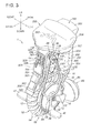
FIG. 3 is a perspective view of the inverted pendulum type vehicle according to the present embodiment. -
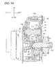
FIG. 4 is a perspective view of a vehicle body frame used in the inverted pendulum type vehicle according to the present embodiment. -
FIG. 5 is a side elevational view, partly in section, of a seat supporting section of the inverted pendulum type vehicle according to the present embodiment. -
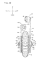
FIG. 6 is a front elevational view selectively showing a traveling unit and a driving unit of the inverted pendulum type vehicle according to the present embodiment. -
FIG. 7 is a front elevational view selectively showing the traveling unit and the driving unit of the inverted pendulum type vehicle according to the present embodiment and showing the traveling unit in a sectional view. -
FIG. 8 is an enlarged sectional view of an axle supporting section of the inverted pendulum type vehicle according to the present embodiment. -
FIG. 9 is a side elevational view selectively showing the traveling unit and the driving unit of the inverted pendulum type vehicle according to the present embodiment and showing the traveling unit in a sectional view. -
FIG. 10 is a sectional view of a reduction gear used in the driving unit of the inverted pendulum type vehicle according to the present embodiment. -
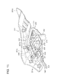
FIG. 11 is a lower side perspective view showing a lifting mechanism for a seat. -
FIG. 12 is a plan view showing the lifting mechanism for a seat. -
FIG. 13 is an upper side perspective view showing the lifting mechanism for a seat which is at a lowered position. -
FIG. 14 is an upper side perspective view showing the lifting mechanism for a seat which is at a raised position. -
FIG. 15 is a partial exploded perspective view of the seat. -
FIG. 16 is an upper side perspective view illustrating a state in which a lid of a battery case is open. -
FIG. 17 is a side elevational view of the inverted pendulum type vehicle in a rearwardly inclined state. -
FIG. 18 is a partial side elevational view showing a modification to the seat. -
FIG. 19 is a front elevational view selectively showing a traveling unit and a driving unit of an inverted pendulum type vehicle according to another embodiment. - In the following, an embodiment of an inverted pendulum type vehicle of the present invention is described with reference to the drawings. In the following description, directions are defined with reference to an occupant seated on the inverted pendulum type vehicle.
- The inverted
pendulum type vehicle 1 includes a travelingunit 50 which configures a wheel, a leftside driving unit 90 and a rightside driving unit 130 for driving the travelingunit 50, and anelectrical unit 300 for controlling the leftside driving unit 90 and the rightside driving unit 130. The invertedpendulum type vehicle 1 further includes abattery pack 250 for supplying electric power to theelectrical unit 300, and aseat unit 170 on which an occupant is to be seated. The travelingunit 50, leftside driving unit 90, rightside driving unit 130,electrical unit 300,battery pack 250 andseat unit 170 are supported on avehicle body frame 10 which configures a vehicle body skeleton. - As shown in
FIG. 4 , thevehicle body frame 10 is formed by welding a plurality of bent pipe members to each other. The pipe members may be circular pipes made of steel or aluminum. Thevehicle body frame 10 includes a travelingunit supporting section 12 for supporting the traveling unit, and a drivingunit supporting section 14 connected to an upper portion of the travelingunit supporting section 12 and supporting the driving unit thereon. Thevehicle body frame 10 further includes abattery supporting section 16 connected to a rear portion of the travelingunit supporting section 12 and supporting thebattery pack 250 thereon. - The
vehicle body frame 10 includes a center post (lifting apparatus supporting member) 44 in the form of a pipe member which extends upwardly and downwardly and is open at the opposite upper and lower ends thereof. Thecenter post 44 is connected to an upper portion of the travelingunit supporting section 12. A pair of U-shaped slits are formed at a lower end of thecenter post 44 such that they extend through thecenter post 44 in the leftward and rightward direction and continue to the lower end face of thecenter post 44. The travelingunit supporting section 12 is formed by bending a pipe member in an annular saddle shape and is received at rear end portions thereof in and welded to the slits. - The traveling
unit supporting section 12 has afront edge portion 12A and a rear edge portion 12B in pair in the forward and backward direction extending in the leftward and rightward direction. The travelingunit supporting section 12 further has a pair of left andright side portions 12C of a substantially U shape which have left ends and right ends connecting to the left ends and the right ends, respectively, of the front edge portion and the rear edge portion and project, at central portions thereof, to the outer sides in the widthwise direction and extend downwardly. The travelingunit supporting section 12 is joined at the rear edge portion 12B thereof to thecenter post 44. A pair of left andright gussets 46 of a substantially triangular shape are joined to the joining portion between the rear edge portion 12B and thecenter post 44 to reinforce the joining portion. - Left and right
step supporting pipes 36 are coupled to lower portions of the left andright side portions 12C and extend downwardly. A pair ofstep attachment plates 38 are coupled to the front side of the left and rightstep supporting pipes 36 and extend forwardly such that faces thereof are directed leftwardly and rightwardly. A pair ofsteps 40 for supporting the sole of the feet of the occupant are provided in a projecting manner on outer faces of the left and rightstep attachment plates 38 in the vehicle widthwise direction. - A pair of plate-shaped
axle supporting plates 20 are joined to lower portions of the left andright side portions 12C such that they extend downwardly and have faces directed leftwardly and rightwardly. Theaxle supporting plates 20 are coupled at a front edge thereof to a rear portion of thestep supporting pipes 36. A bearing recessedportion 20A is formed in each of the left and rightaxle supporting plates 20 such that it extends through theaxle supporting plate 20 in the leftward and rightward direction and is open downwardly. - The driving
unit supporting section 14 is formed by disposing a plurality of pipes including thecenter post 44 in a cage shape and is provided immediately above the travelingunit supporting section 12. The drivingunit supporting section 14 has afirst pipe 14A and a second pipe 14B. Thefirst pipe 14A extends obliquely upwardly rearwardly from a right end portion of thefront edge portion 12A of the travelingunit supporting section 12, extends upwardly in a curved state, is bent and then extends rearwardly, is curved and extends downwardly leftwardly and is joined to an outer face at an intermediate portion of thecenter post 44 in the upward and downward direction. - The second pipe 14B extends obliquely upwardly rearwardly from a left end portion of the front edge portion of the traveling
unit supporting section 12, is bent and extends upwardly, and is further bent and extends rearwardly to form a free end. - A pair of
third pipes 14C are joined at a front end thereof to a lower end portion of thefirst pipe 14A and the second pipe 14B which extend rearwardly upwardly in an inclined relationship. Thethird pipes 14C individually extend in the forward and backward direction and are joined at a rear end thereof to the rear edge portion 12B of the travelingunit supporting section 12. Afourth pipe 14D is coupled at a front end thereof to an intermediate portion of the portion of thefirst pipe 14A which extends upwardly. Thefourth pipe 14D extends rearwardly, is bent and extends downwardly and is joined at a rear end thereof to the right sidethird pipe 14C. Afifth pipe 14E is joined at a front end thereof to an intermediate portion of the portion of the second pipe 14B which extends upwardly. Thefifth pipe 14E extends rearwardly, is bent so as to extend rearwardly upwardly, is further bent so as to extend rightwardly and is joined to an outer face of an intermediate portion of thecenter post 44. The portion of thefirst pipe 14A which extends forwardly and backwardly at an upper portion thereof and an upper end portion of the second pipe 14B are joined together by asixth pipe 14F which extends horizontally in the leftward and rightward direction. - The portion of the
fourth pipe 14D which extends forwardly and backwardly and the portion of thefifth pipe 14E which extends forwardly and backwardly are joined together by aseventh pipe 14G which extends horizontally in the leftward and rightward direction. The portions of thefirst pipe 14A and the second pipe 14B which extend upwardly are joined together by aconnection plate 14H which extends in the leftward and rightward direction. By connecting a portion of the driving unit supporting section 14 (first pipe 14A,fifth pipe 14E) to an intermediate portion (or an upper portion) of thecenter post 44, aseat 200 movable in the upward and downward directions can be supported stably. It is to be noted that a similar effect can be obtained also by a configuration wherein a portion of thebattery supporting section 16 is connected to an intermediate portion (or an upper portion) of thecenter post 44. - The driving
unit supporting section 14 has a cage shape having two upper and lower stages having a substantially cubic upper side cage portion 14I and a lowerside cage portion 14J. The upper side cage portion 14I is disposed upwardly with respect to the drivingunit supporting section 14 while the lowerside cage portion 14J is disposed downwardly with respect to the drivingunit supporting section 14 across the boundary provided by theseventh pipe 14G. The upper side cage portion 14I has a frame (left side frame-shaped portion) which forms a left side portion of the upper side cage portion 14I defined by an upper half portion of the second pipe 14B and thefifth pipe 14E, and a left side drivingunit attachment plate 22 which is a plate-shaped gusset is coupled to the frame of the upper side cage portion 14I. The lowerside cage portion 14J has a frame (right side frame-shaped portion) which forms a right side portion of the lowerside cage portion 14J defined by a lower half portion of thefirst pipe 14A, thethird pipe 14C on the right side andfourth pipe 14D, and a right side drivingunit attachment plate 24 which is a plate-shaped gusset is coupled to the frame of the lowerside cage portion 14J. The left side drivingunit attachment plate 22 and the right side drivingunit attachment plate 24 are disposed in an vertically offset state and in parallel to each other on the outer sides in the vehicle body widthwise direction. - The
battery supporting section 16 is formed from a pipe disposed in a channel shape open forwardly as viewed in plan, and is jointed at left and right end portions thereof to rear portions of theside portions 12C of the travelingunit supporting section 12. Ashelf board 17 in the form of a flat plate is provided on the inner side of the channel shape of thebattery supporting section 16. Thebattery supporting section 16 and theshelf board 17 exhibit a shelf shape protruding rearwardly with respect to the travelingunit supporting section 12. To a rear portion of each theside portions 12C of the travelingunit supporting section 12, areinforcement pipe 30 formed in a U shape (semicircular shape) is joined at the opposite ends thereof. In other words, TheU-shaped reinforcement pipe 30 is provided in a projecting manner at a rear portion of theside portion 12C of the travelingunit supporting section 12. An upper portion of the left andright reinforcement pipes 30 and a lower portion of the opposite left and right portions of thebattery supporting section 16 are joined together by a pair of left and rightlinear brace pipes 32. Thebrace pipes 32 serve as braces to reinforce thebattery supporting section 16. - The
vehicle body frame 10 including the travelingunit supporting section 12, drivingunit supporting section 14 andbattery supporting section 16 is covered with anouter shell 18 made of a synthetic resin and indicated by imaginary lines inFIG. 1 . - The traveling
unit 50 is disposed between the left andright side portions 12C of the travelingunit supporting section 12. As shown inFIGS. 1 to 3 ,6 and7, the travelingunit 50 includes ahollow axle 54 extending horizontally in the vehicle widthwise direction (leftward and rightward direction), and left and right drivingdisks 58 supported for rotation independently of each other on an outer periphery of thehollow axle 54. The travelingunit 50 further includes an annularmain wheel 52 penetrated by thehollow axle 54 and disposed between the left and right drivingdisks 58, and left and right drivenpulleys 60 for a cog belt fastened to the left and right drivingdisks 58 bybolts 59. The left and right drivingdisks 58 and the left and right drivenpulleys 60 are disposed on the same axial line with a central axial line of thehollow axle 54 as a common axial line. As shown inFIG. 8 , a columnar pulley attachingshaft portion 58C is provided in a projecting manner at the center of an outer face of each of the drivingdisks 58 in the vehicle widthwise direction, and an axial through-hole 60A is formed in each of the driven pulleys 60. The drivenpulley 60 is fixed to the outer side face of thedriving disk 58 in the vehicle widthwise direction by thebolts 59 in a state in which the pulley attachingshaft portion 58C is inserted in the axial through-hole 60A. - The
main wheel 52 is a driving wheel which is driven based on inverted pendulum control and is configured, as shown inFIG. 7 , from acircular ring member 62 made of metal, and a plurality of driven rollers (free rollers) 64 attached to an outer periphery of thecircular ring member 62. Themain wheel 52 contacts with the ground at the drivenrollers 64 thereof. Each of the drivenrollers 64 is configured from a cylindricalmetal base portion 64A mounted for rotation on the outer periphery of thecircular ring member 62 and a cylindrical rubber outerperipheral portion 64B of vulcanized rubber adhered to an outer periphery of themetal base portion 64A. A plurality of drivenrollers 64 are provided in the ring direction (circumferential direction) of thecircular ring member 62 and can individually rotate (rotate) around a tangential line to thecircular ring member 62 at the disposition position of the drivenrollers 64 themselves. In short, themain wheel 52 is configured by combining the plural drivenrollers 64, which can rotate independently of each other, such that they form a ring. Strictly speaking, the plural drivenrollers 64 are combined so as to form a polygon having a number of angles corresponding to the number of drivenrollers 64 thereby to form themain wheel 52. - The left and right driving
disks 58 have a disk shape of an outer diameter smaller than a central radius of thecircular ring member 62, and an outer peripheral portion thereof is a conical outerperipheral portion 58D which has a substantially truncated conical shape. A plurality of drivingrollers 66 made of metal are supported for rotation at equal distances in the circumferential direction on the conical outerperipheral portion 58D. The drivingrollers 66 of the leftside driving disk 58 and the drivingrollers 66 of the rightside driving disk 58 are disposed in a leftwardly and rightwardly symmetrical relationship with each other, and the centers of the drivingrollers 66 are disposed in a twisted relationship with the center of rotation of thedriving disk 58. Consequently, the left and right drivingrollers 66 have leftwardly and rightwardly symmetrical shapes and have an inclined disposition similar to teeth of a helical gear wheel. - The
hollow axle 54 supports the left and right drivingdisks 58 for rotation independently of each other through two pairs of ball bearings (radial ball bearings) 56. Theball bearings 56 are disposed in a spaced relationship from each other in the direction of the axial line of thehollow axle 54 on an outer periphery of thehollow axle 54. As shown inFIG. 8 , the left and right drivingdisks 58 have an axial through-holes 58A. Increaseddiameter portions 58B which are increased in diameter in an offset state are formed at opening ends of the axial through-holes 58A on the opposite sides in the direction of the axial line. Acollar member 57 is fitted on an outer periphery of thehollow axle 54, and the twoball bearings 56 are fitted at the inner race thereof on thehollow axle 54 in such a manner as to sandwich thecollar member 57 therebetween and fitted at the outer race thereof with the increaseddiameter portions 58B. The twoball bearings 56 abut at an end face of the outer race thereof with positioning steppedportions 58E formed at end portions of the increaseddiameter portions 58B and abut at an end face of the inner race thereof with thecollar member 57 such that they are positioned in the direction of the axial line and disposed in a spaced relationship from each other. It is to be noted that the axial length of thecollar member 57 and the dimension by which the positioning steppedportions 58E formed in pair on the opposite sides of the axial through-holes 58A of the axial through-holes 58A in the direction of the axial line are equal to each other. - A pair of positioning stepped
portions 54A are formed in a spaced relationship by a predetermined distance from each other in the direction of the axial line on the outer periphery of thehollow axle 54 by reducing the diameter on the end portion sides of thehollow axle 54. The distance between the left and right drivingdisks 58 in the direction of the axial line is set by abutment of an end face of the inner race of theball bearing 56 on the inner side in the direction of the axial line from between the twoball bearings 56 with the positioning steppedportion 54A. - A
nut 68 is screwed with each of male threadedportions 54B formed in the proximity of left and right end portions of thehollow axle 54. By tightening of thenut 68, a ring-shapedprotrusion 68A formed on the inner diameter side of thenut 68 presses an end face of the inner race of theball bearing 56 on the outer side in the direction of the axial line from between the twoball bearings 56. Consequently, the inner races of the twoball bearings 56 and thecollar member 57 are sandwiched by the positioning steppedportion 54A and thenut 68 and positioned in the direction of the axial line of thedriving disk 58 with respect to thehollow axle 54. Consequently, thedriving disk 58 is supported for rotation by a supporting structure of low frictional resistance. - The outer diameter of the nut 68 (flange outer diameter) is formed greater than the outer diameter of the outer race of the
ball bearing 56. In short, the outer diameter of thenut 68 is formed greater than the inner diameter of the axial through-hole 58A of thedriving disk 58. Consequently, The disposition position of theball bearing 56 is hidden by thenut 68 thereby to form a labyrinth seal so that dust becomes less likely to enter theball bearing 56. - Meanwhile, the axial through-
hole 60A of the drivenpulley 60 is formed greater than the outer diameter of thenut 68. In short, the axial through-hole 60A has an inner diameter which allows thenut 68 to extend through the axial through-hole 60A in the direction of the axial line. Consequently, in a state in which thenut 68 is screwed with the hollow axle, the drivenpulley 60 can be mounted on and removed from thedriving disk 58. - The left and right driving
disks 58 assembled to thehollow axle 54 in such a manner as described above are supported on a substantially same axial line (concentrically) in such a manner that themain wheel 52 is sandwiched from the opposite left and right sides by the ring-shaped roller train groups by the left and right drivingrollers 66 as shown inFIGS. 2 and6 . Consequently, themain wheel 52 is supported between the left and right drivingdisks 58 and prevented from coming out from between them. - More particularly, an outer circumferential face of the driving
rollers 66 of thedriving disk 58 contacts in such a manner as to be pressed against an outer circumferential face of the rubber outerperipheral portion 64B of the drivenrollers 64 of themain wheel 52. The contact position between the drivingrollers 66 and the drivenrollers 64 is leftwardly and rightwardly symmetrical between the left and right drivingdisks 58. Further, the contact position is on that portion of the outer circumferential face of the drivenroller 64 which is positioned inwardly (rotational center side) in a diametrical direction with respect to a diametrical position of thecircular ring member 62 and the outer circumferential face of the drivingroller 66 at the location. This signifies that the dimension of the minimum distance in the direction of the axial line between the drivingrollers 66 of the left and right drivingdisks 58 is smaller than the outer diametrical dimension of the drivenrollers 64. - The driving
rollers 66 of the left and right drivingdisks 58 sandwich the drivenrollers 64 from the opposite left and right sides to support themain wheel 52 in a no-axis state between the left and right drivingdisks 58 and can rotate (revolve) around the center of themain wheel 52 itself together with the left and right drivingdisks 58. - An assembly (subassembly) as the traveling
unit 50 including the left and right drivingdisks 58, left and right driven pulleys 60,hollow axle 54 andmain wheel 52 is configured in such a manner as described above. - In this subassembly, the dimension of the distance between the left and right driving
disks 58 in the direction of the axial line is uniquely set to an appropriate value depending upon the distance in the direction of the axial line between the two left and right positioning steppedportions 54A formed on the outer periphery of thehollow axle 54. Consequently, the setting accuracy of friction between the drivingrollers 66 of thedriving disk 58 and the drivenrollers 64 of themain wheel 52 is improved, and management of the same is facilitated. - The traveling
unit 50 is disposed between the left andright side portions 12C of the travelingunit supporting section 12 and is supported by the bearing recessedportions 20A of theaxle supporting plates 20 at the opposite ends of thehollow axle 54. A reduceddiameter end portion 54C is formed at the opposite left and right ends of thehollow axle 54 such that it is reduced in diameter by formation of a stepped portion. The left and right reduceddiameter end portions 54C are inserted in the bearing recessedportions 20A such that the stepped portions thereof abut with theaxle supporting plates 20. Acollar member 69 is fitted on the end portion sides passing through the bearing recessedportions 20A of the left and right reduceddiameter end portions 54C. A headedbolt 72 is inserted in the central through-hole 55 of thehollow axle 54 such that it passes awasher 70 from one end. An end portion of the headedbolt 72 projects from the other end side of the central through-hole 55, passes through thewasher 70 and is screwed with anut 74. The head of the headedbolt 72 and thenut 74 press thecollar members 69 through thewashers 70. Consequently, each of theaxle supporting plates 20 is sandwiched between the stepped portion of the reduceddiameter end portion 54C and the headedbolt 72 or thenut 74 with thecollar member 69 and thewasher 70 interposed therebetween. - Assembly of the traveling
unit 50 configured as a subassembly to the travelingunit supporting section 12 is carried out in the following manner. First, the travelingunit 50 is disposed between the left andright side portions 12C of the travelingunit supporting section 12. Then, an outer periphery of the reduceddiameter end portions 54C formed at the opposite ends of thehollow axle 54 is fitted from the lower side (opening side) into the downwardly open bearing recessedportion 20A (refer toFIG. 4 ) of theaxle supporting plates 20 fixed to the left andright side portions 12C. - Then, the
collar member 69 is fitted with an outer periphery of one of the reduceddiameter end portions 54C of thehollow axle 54 on the outer side in the direction of the axial line with respect to the portion of the reduceddiameter end portion 54C at which the reduceddiameter end portion 54C engages with theaxle supporting plate 20. Then, the headedbolt 72 serving as a supporting shaft is inserted from one of the axial ends of thehollow axle 54 into the central through-hole 55 of thehollow axle 54 in a state in which thewasher 70 is sandwiched between an end face of thecollar member 69 and the headedbolt 72. The headedbolt 72 is projected at an end thereof outwardly from the central through-hole 55 through the central through-hole 55. - Then, the
other collar member 69 is fitted with an outer periphery of the other reduceddiameter end portion 54C of thehollow axle 54 on the other side in the direction of the axial line with respect to the portion of the reduceddiameter end portion 54C which engages with theaxle supporting plate 20. Then, thenut 74 is tightened to an end threadedportion 72A of the headedbolt 72 which projects outwardly from the central through-hole 55 with theother washer 70 sandwiched between the end face of thecollar member 69 and thenut 74. The assembly of the travelingunit 50 to the travelingunit supporting section 12 is completed therewith. - The left and right driving
disks 58, left and right driven pulleys 60,hollow axle 54 andmain wheel 52 can be unitized without complicating the structure in this manner, and the unit can be attached simply to thevehicle body frame 10. - The traveling
unit 50 may include atail wheel unit 80 supported on thehollow axle 54 through atail wheel arm 78 as in the present embodiment. Thetail wheel arm 78 extends substantially linearly at a rear end portion thereof and has a front end portion bifurcated into forkedportions 78A. Thetail wheel arm 78 is supported for pivotal motion on thecollar members 69 at the forkedportions 78A through ball bearings (radial ball bearing) 76. Thecollar members 69 are mounted between the forkedportions 78A on the left and right reduceddiameter end portions 54C of thehollow axle 54 so as to dispose the left and right drivingdisks 58, left and right drivenpulleys 60 and themain wheel 52 of the travelingunit 50. Consequently, thetail wheel arm 78 can extend behind themain wheel 52 without interfering with the left and right drivingdisks 58, left and right drivenpulleys 60 andmain wheel 52. - A rear
side limit stopper 34 is attached to thereinforcement pipe 30. The rearside limit stopper 34 abuts with an upper face of thetail wheel arm 78 to restrict upward pivotal motion of thetail wheel arm 78 around the hollow axle 54 (pivotal motion of the tail wheel arm in the counterclockwise direction in a state in which the vehicle is viewed from leftwardly (refer toFIG. 1 )). In other words, a maximum rearward rollover angle (maximum rearward inclination angle) of thevehicle body frame 10 is set. - A front
side limit stopper 42 is attached to thestep supporting pipe 36. The frontside limit stopper 42 abuts with a lower face of thetail wheel arm 78 to restrict downward pivotal motion of thetail wheel arm 78 around the hollow axle 54 (pivotal motion of the tail wheel arm in the clockwise direction in a state in which the vehicle is viewed from leftwardly (refer toFIG. 1 )). In other words, a forward maximum rollover angle (maximum forward inclination angle) of thevehicle body frame 10 is set. - The
tail wheel unit 80 is supported at a rear end of thetail wheel arm 78. Thetail wheel unit 80 includes atail wheel 82 supported on thetail wheel arm 78, anelectric motor 84 for driving thetail wheel 82 to rotate, and anouter shell 85 for covering thetail wheel 82 and theelectric motor 84. Thetail wheel arm 78 can pivot around the axial line of thehollow axle 54, and thetail wheel unit 80 places thetail wheel 82 into contact with the ground by the weight of thetail wheel unit 80 itself. - The
tail wheel 82 may be an omnidirectional wheel configured from a ring member supported for rotation on thetail wheel arm 78 and a free roller attached for rotation on an outer periphery of the ring member. The ring member is driven to rotate around the center axial line extending in the vehicle body forward and backward direction in a state in which the free roller contacts with the ground, namely, around the center axial line perpendicular to the axial line of the hollow axle 54 (axial line of the center of rotation of the main wheel 52) as viewed in plan, by theelectric motor 84. - The left
side driving unit 90 is disposed in the upper side cage portion 14I as shown inFIGS. 1 and3 . The leftside driving unit 90 is configured, as shown inFIGS. 6 ,7 and9 , anelectric motor 92, areduction gear 96 connected to an output power shaft (motor output power shaft) 94 of theelectric motor 92, and a drivingpulley 100 for a cog belt disposed leftwardly of thereduction gear 96 and connected to an output power shaft (reduction gear output power shaft) 98 of thereduction gear 96. - The
reduction gear 96 is of the gear wheel type having two parallel axes and includes agear box 102 of the wet type having an enclosed structure directly connected to the output power shaft side of theelectric motor 92 as shown inFIG. 10 . Thereduction gear 96 includes an end portion of the motoroutput power shaft 94, the reduction gearoutput power shaft 98, anintermediate shaft 112, asmall gear wheel 114, alarge gear wheel 116, anothersmall gear wheel 118, and alarge gear wheel 120 in thegear box 102. Theoutput power shaft 98 is disposed for rotation on the same axial line with the motoroutput power shaft 94 byball bearings intermediate shaft 112 is disposed for rotation on an axial line parallel to the reduction gearoutput power shaft 98 byball bearings small gear wheel 114 is fixed to an end portion of the motoroutput power shaft 94. Thelarge gear wheel 116 is fixed to theintermediate shaft 112 and meshes with thesmall gear wheel 114. Thesmall gear wheel 118 is fixed to theintermediate shaft 112, and thelarge gear wheel 120 is fixed to the reduction gearoutput power shaft 98 and meshes with thesmall gear wheel 118. - In the
reduction gear 96, a disposition portion of theintermediate shaft 112 thereof projects outwardly in a radial direction from the outer face of theelectric motor 92, and this projectingportion 102A is positioned on the obliquely upper rear side with respect to the position of the center axial line of theelectric motor 92. - An end portion of the reduction gear
output power shaft 98 projects to the opposite side (left side) of thegear box 102 to the side of theelectric motor 92, and the drivingpulley 100 is fixed to the end portion. In other words, thereduction gear 96 is disposed between theelectric motor 92 and the reduction gearoutput power shaft 98. - A plurality of threaded holes (not shown) are formed in a left wall of the
gear box 102, and a plurality of (in the example shown, three)bolt penetrating holes 22A are formed in the left side drivingunit attachment plate 22 as shown inFIG. 4 .Attachment bolts 26 extending through thebolt penetrating holes 22A are screwed in the threaded holes to fix thereduction gear 96, namely, the leftside driving unit 90, to the left side drivingunit attachment plate 22. It is to be noted that the leftside driving unit 90 can be placed into the upper side cage portion 14I from the right side, at which the left side drivingunit attachment plate 22 does not exist and which is open, beginning with thereduction gear 96. - The reduction gear
output power shaft 98 projects outwardly through acutaway portion 22B (refer toFIG. 4 ) formed in the left side drivingunit attachment plate 22, and the drivingpulley 100 is attached to a position of the outwardly projecting end of the reduction gearoutput power shaft 98 very proximate to the outer side face of the left side drivingunit attachment plate 22. Acog belt 122 extends between the drivingpulley 100 and the driven pulleys 60. Since the drivingpulley 100 around which thecog belt 122 extends is positioned on the left side drivingunit attachment plate 22 side together with the reduction gearoutput power shaft 98, the left side power transmission section including the drivingpulley 100 is supported more firmly by the left side drivingunit attachment plate 22. The left side drivingunit attachment plate 22 is an attachment plate of the leftside driving unit 90 to thevehicle body frame 10 and simultaneously serves as a gusset which acts to raise the rigidity of the upper side cage portion 14I and raise the supporting rigidity of the left side power transmission section. - It is to be noted that, since the
cutaway portion 22B of the left side drivingunit attachment plate 22 is so sized that the drivingpulley 100 in a state in which it is fixed to the reduction gearoutput power shaft 98 can pass therethrough in the vehicle widthwise direction, the leftside driving unit 90 wherein the drivingpulley 100 is fixed to the reduction gearoutput power shaft 98 can be assembled to the upper side cage portion 14I. - Each of the
bolt penetrating holes 22A is an elongated hole elongated in the upward and downward direction, and the fixing position of the leftside driving unit 90 to the left side drivingunit attachment plate 22 in the upward and downward direction can be changed within the range of the elongated hole. By changing the fixing position of the leftside driving unit 90 in the upward and downward direction, the tension to be applied to thecog belt 122 can be changed. In short, thebolt penetrating hole 22A cooperates with the mountingbolt 26, which extends through thebolt penetrating hole 22A, so as to serve as a guide portion for the movement of the leftside driving unit 90 in the upward and downward direction, and the tension to be applied to thecog belt 122 is changed by change of the fixing position of the leftside driving unit 90 in the upward and downward direction. - An
adjustment bolt 124 is attached to thesixth pipe 14F such that it extends upwardly and downwardly through thesixth pipe 14F as shown inFIGS. 4 and9 . Theadjustment bolt 124 is screwed in a threaded hole (not shown) formed in an upper wall of thegear box 102. - By changing the screwed amount of the
adjustment bolt 124 into the threaded hole in a state in which the mountingbolts 26 are loosened, the entire leftside driving unit 90 moves upwardly or downwardly with respect to the upper side cage portion 14I (sixth pipe 14F). By the upward or downward movement of the leftside driving unit 90, the tension to be applied to thecog belt 122 can be adjusted. By fastening theadjustment bolt 124 to thesixth pipe 14F by alock nut 126, the tension variation of thecog belt 122 can be suppressed. - The right
side driving unit 130 is disposed in the lowerside cage portion 14J as shown inFIGS.1 and3 . The rightside driving unit 130 is equivalent to the leftside driving unit 90 reversed leftwardly and rightwardly. As shown inFIGS. 6 ,7 and9 , the rightside driving unit 130 is configured from anelectric motor 132, areduction gear 136 attached to the output power shaft (not shown) side (right side) of theelectric motor 132, and a drivingpulley 140 for a cog belt attached to an output power shaft (reduction gear output power shaft) 138 hereinafter described of thereduction gear 136. - The
reduction gear 136 is of the gear wheel type of two parallel shafts and includes a wettype gear box 142 of an enclosed structure directly coupled to the output power shaft side of theelectric motor 132. Thegear box 142 has an internal structure similar to that of thereduction gear 96 including the reduction ratio except that it has a leftwardly and rightwardly inversed disposition, and therefore, detailed description of the internal structure thereof is omitted herein. Thereduction gear 136 projects, at a disposition portion of an intermediate shaft (not shown) thereof, outwardly in a radial direction from an outer profile of theelectric motor 132. This projectingportion 142A is positioned on the front side of the vehicle body with respect to the position of the axial line of the center of theelectric motor 132. - The reduction gear
output power shaft 138 projects, at an end portion thereof, to the opposite side (right side) of thegear box 142 to the side of theelectric motor 132, and the drivingpulley 140 is fixed to the end portion thereof. In other words, thereduction gear 136 is disposed between theelectric motor 132 and the reduction gearoutput power shaft 138. - A plurality of threaded holes (not shown) are formed in the right wall of the
gear box 142, and a plurality of (in the example shown, three)bolt penetrating holes 24A are formed in the right side drivingunit attachment plate 24. By screwing mountingbolts 28 penetrating thebolt penetrating holes 24A into the threaded holes, thereduction gear 136, namely, the rightside driving unit 130, is fixed to the right side drivingunit attachment plate 24. It is to be noted that the rightside driving unit 130 can be placed into the lowerside cage portion 14J from the left side, on which the right side drivingunit attachment plate 24 does not exist and which is open, beginning with thereduction gear 136. - The reduction gear
output power shaft 138 passes through acutaway portion 24B (refer toFIG. 4 ) formed in the right side drivingunit attachment plate 24 and projects to the outer side, and the drivingpulley 140 is attached to a position of the outer side projecting end of the reduction gearoutput power shaft 138 very close to the outer side face of the right side drivingunit attachment plate 24. Anendless cog belt 144 extends between and around the drivingpulley 140 and the right side drivenpulley 60. The drivingpulley 140 around which thecog belt 144 extends is positioned on the side of the right side drivingunit attachment plate 24 together with the reduction gearoutput power shaft 138. Therefore, the right side power transmission section including the drivingpulley 140 is supported firmly by the right side drivingunit attachment plate 24. The right side drivingunit attachment plate 24 servers as an attachment plate for the rightside driving unit 130 to thevehicle body frame 10 and simultaneously acts as a gusset to raise the rigidity of the lowerside cage portion 14J and raise the supporting rigidity of the right side power transmission section. - Each
bolt penetrating hole 24A is an elongated hole elongated in the upward and downward direction, and the fixing position of the rightside driving unit 130 to the right side drivingunit attachment plate 24 in the upward and downward direction can be changed within the range of this elongated hole. This serves as adjustment mechanism for the initial tension. By changing the fixing position of the rightside driving unit 130 in the upward and downward direction, the tension to be applied to thecog belt 144 can be changed. In other words, thebolt penetrating hole 24A cooperates with the mountingbolt 28 extending through thebolt penetrating hole 24A to serve as a guide portion for movement of the rightside driving unit 130 in the upward and downward direction. Further, the tension to be applied to thecog belt 144 is changed by changing the fixing position of the rightside driving unit 130 in the upward and downward direction. - An
adjustment bolt 146 is attached to theseventh pipe 14G such that it extends upwardly and downwardly through theseventh pipe 14G as shown inFIGS. 4 and9 . Theadjustment bolt 146 is screwed in a threaded hole (not shown) formed in an upper wall of thegear box 142. - By changing the screwed amount of the
adjustment bolt 146 into the threaded hole in a state in which the mountingbolts 28 are loosened, the rightside driving unit 130 moves upwardly or downwardly with respect to the lowerside cage portion 14J (seventh pipe 14G). The tension to be applied to thecog belt 144 can be adjusted by this upward or downward movement of the rightside driving unit 130. By fastening theadjustment bolt 146 to theseventh pipe 14G by alock nut 148, the tension variation of thecog belt 144 can be suppressed. - The
adjustment bolts side driving unit 90 and the rightside driving unit 130 from above and support the leftside driving unit 90 and the rightside driving unit 130 at positions at which they are opposed to thecog belts side driving unit 90 and the rightside driving unit 130 upon tension adjustment is facilitated. - It is to be noted that such setting is used that, even if the left
side driving unit 90 on the upper stage is positioned at its lowermost position, aspace 149 into which a tool T or a jig for turning theadjustment bolt 146 can be inserted is assured between a bottom portion of the leftside driving unit 90 and the head of theadjustment bolt 146 on the lower stage. Where the lower frame (fourth pipe 14D,fifth pipe 14E) of the upper side cage portion 14I serves as an upper frame of the lowerside cage portion 14J and theadjustment bolt 146 is attached to theseventh pipe 14G which bridges thefourth pipe 14D and thefifth pipe 14E as in the case of the embodiment shown in the figures, the head of theadjustment bolt 146 is accessed from the side (right side) to which the left side drivingunit attachment plate 22 is not attached. Consequently, the tension to thecog belt 144 can be adjusted by an operation of theadjustment bolt 146 without being obstructed by thecog belt 122. It is to be noted that, by accessing also theadjustment bolt 124 on the upper stage from the side (right side) to which the left side drivingunit attachment plate 22 is not attached, tension adjustment of thecog belts - The left and right driven
pulleys 60 have an equal number of teeth, and the left and right drivingpulleys pulleys 60 and the drivingpulleys right cog belts pulleys 60 and the drivingpulleys pulleys 60 and the drivingpulleys - In this manner, the left
side driving unit 90 and the rightside driving unit 130 are disposed in an offset state on the two upper and lower stages while they are reversed leftwardly and rightwardly relative to each other, and overlap in most part thereof with each other as viewed in plan. Theelectric motor 92 of the leftside driving unit 90 on the upper stage is provided in a displaced relationship to the right side opposite to the disposition side of thereduction gear 96 with respect to a vehicle body center line C (refer toFIG. 6 ) in the vehicle widthwise direction (leftward and rightward direction). Meanwhile, theelectric motor 132 of the rightside driving unit 130 on the lower stage is provided in a displaced relationship to the left side opposite to the arrangement side of thereduction gear 136 with respect to the vehicle body center line C (refer toFIG. 6 ) in the vehicle widthwise direction (leftward and rightward direction). - By this disposition, the
electric motor 92 of the leftside driving unit 90 on the upper stage is positioned just above thereduction gear 136 of the rightside driving unit 130 on the lower stage. Further, thereduction gear 96 of the leftside driving unit 90 on the upper stage is positioned just above theelectric motor 132 of the rightside driving unit 130 on the lower stage. - In the inverted
pendulum type vehicle 1 of the present embodiment, the leftside driving unit 90 and the rightside driving unit 130 are disposed in an offset state on the two upper and second stages at positions above themain wheel 52 and overlap at most part thereof with each other as viewed in plan as described hereinabove. Therefore, in comparison with a case in which theelectric motors side driving unit 90 and the rightside driving unit 130 in the same vehicle body width. - Consequently, upsizing (increase in torque) of the
electric motors driving disk 58 and hence driving torque of themain wheel 52 can be increased. Besides, since the reduction gears 96 and 136 are of the two parallel shaft type in which the output power shafts (94) of theelectric motors output power shafts electric motors side driving unit 90 and the rightside driving unit 130 having output power torque ready for a model of different driving torque can be disposed suitably without changing the vehicle classification. - Further, since the left
side driving unit 90 and the rightside driving unit 130 are disposed on the two upper and lower stages, the position of the center of gravity of the invertedpendulum type vehicle 1 can be positioned upwardly and the inverted pendulum control of the invertedpendulum type vehicle 1 is facilitated. - Since the left
side driving unit 90 and the rightside driving unit 130 are disposed in a leftward and rightwardly reversed state on the two upper and lower stages, the balance in weight between the left and the right is enhanced. Besides, theelectric motors electric motors unit attachment plate 22 and the right side drivingunit attachment plate 24 do not exist, also the cooling performance is enhanced advantageously and wiring and connection of a harness for electric power (not shown) to theelectric motors - While the projecting
portion 102A of thereduction gear 96 of the leftside driving unit 90 is positioned on the obliquely upward rearward side with respect to the position of the center axial line of theelectric motor 92, the projectingportion 142A of thereduction gear 136 of the rightside driving unit 130 is positioned forwardly with respect to the position of the center axial line of theelectric motor 132. In other words, the projecting directions of the projectingportions - Where the projecting
portion 102A of thereduction gear 96 on the upper stage is positioned on the obliquely upward rearward side with respect to the position of the center axial line of theelectric motor 92, the position of the center of gravity of the invertedpendulum type vehicle 1 is positioned further upwardly, and inverted pendulum control of the invertedpendulum type vehicle 1 is facilitated. That the projectingportion 142A of thereduction gear 136 of the rightside driving unit 130 is positioned forwardly with respect to the position of the center axial line of theelectric motor 132 coincides with that the center of rotation of the reduction gearoutput power shaft 138 of the rightside driving unit 130 is positioned in a displaced relationship to the vehicle body rear side from the center of rotation of the reduction gearoutput power shaft 98 of the leftside driving unit 90. This contributes to space-saving by effective utilization of the space. - Since the left
side driving unit 90 and the rightside driving unit 130 are assemblies of theelectric motors gear boxes side driving unit 90 and the rightside driving unit 130 separately from the cog belt systems of the dry type (drivingpulleys cog belts side driving unit 90, rightside driving unit 130 and the driving systems by the cog belt systems is enhanced. - Further, assembly of the running and driving systems can be carried out readily only by the following procedure. In particular, the subassembly of the left and right driving
disks 58 and the left and right drivenpulleys 60 assembled to thehollow axle 54 and themain wheel 52 assembled between the left and right drivingdisks 58, namely, the traveling unit, is attached to theaxle supporting plates 20 by thebolt 72 and thenut 74. Then, the leftside driving unit 90 and the rightside driving unit 130 to which the drivingpulleys unit supporting section 14. Further, thecog belts pulleys - As shown in
FIG. 9 , the center of rotation of the reduction gearoutput power shaft 98 of the leftside driving unit 90 is located on a vertical line P which passes the center of thehollow axle 54. However, the center of rotation of the reduction gearoutput power shaft 138 of the rightside driving unit 130 is positioned in a displaced relationship to the vehicle body rear side with respect to the center of rotation of the vertical line P which passes the center of thehollow axle 54 as viewed in a side elevation. - As shown in
FIG. 5 , acylindrical bush 47 made of resin is fitted in an upper half portion of the inside of thecenter post 44. Thecylindrical bush 47 has anannular flange portion 47A extending outwardly in diametrical directions at an upper end thereof. Thecylindrical bush 47 is sandwiched at theflange portion 47A thereof between an upper end face of thecenter post 44 and a retainingmember 49 fixed to thecenter post 44 such that thecylindrical bush 47 is supported on thecenter post 44 against movement in the direction of the axial line. - A
telescopic strut 180 is inserted in thecenter post 44 and serves as a support post for supporting the seat for upward and downward movement. In particular, thetelescopic strut 180 is disposed between the drivingunits battery pack 250 in the vehicle body forward and backward direction. Consequently, when thetelescopic strut 180 is used to adjust the height of the seat, the space of the vehicle body is utilized effectively to avoid upsizing of the vehicle body while the drivingunits battery pack 250 which are comparatively heavy can be disposed in a good balance forwardly and backwardly of the telescopic strut 180 (seat 200) thereby to maintain a good gravity center balance of the vehicle body. Thetelescopic strut 180 is configured from a gas spring with a lock (lifting apparatus of the cylinder type) and is inserted in thecenter post 44 with apiston rod 182 positioned on the lower side while an end portion of thepiston rod 182 is fixed to a bottom portion of thecenter post 44 by anut 45. Acylinder tube 184 of thetelescopic strut 180 is fitted for sliding movement with thecylindrical bush 47 such that it can move upwardly and downwardly with respect to thevehicle body frame 10. - An upper end of the
cylinder tube 184 projects upwardly from thecenter post 44. Thecylinder tube 184 is fixed at the upper end thereof to aseat frame 202 of the seat (saddle) 200. Theseat 200 is configured from the above-describedseat frame 202 formed in a substantially quadrangular frame shape by bending a pipe member. Theseat 200 is configured further from abase member 201 in the form of a plate fixed to theseat frame 202, and a seatmain body 206 attached to an upper portion of thebase member 201 and having a cushioning property. Theseat 200 is configured further from aseat bottom cover 204 attached to a lower portion of thebase member 201, andside guard members 207 attached to the opposite left and right sides of theseat bottom cover 204. A seat lifting lever (operation lever) 198 (refer toFIG. 11 ) for carrying out unlocking of thetelescopic strut 180 is disposed on one side portion of theseat bottom cover 204. - The
side guard members 207 are made of a comparatively hard material (here, rubber) and are provided so as to be positioned on the most outer sides in the widthwise direction (leftward and rightward direction) of theseat 200. Consequently, even if the seatmain body 206 is made of a comparatively soft material (here, polyurethane) taking the riding comfort and so forth into consideration, the occupant can assume a stabilized riding posture by grasping the left and rightside guard members 207 as occasion demands when the occupant gets on the invertedpendulum type vehicle 1. Further, as shown inFIG. 2 , the components of the vehicle body are provided so as to be positioned on the inner side of an imaginary line L1 which connects outer edges of the left and rightside guard members 207 and outer edges of the left andright steps 40 to each other. In other words, theseat 200 and thesteps 40 are provided with a width greater than that of theouter shell 18 in the leftward and rightward direction. Consequently, also in a state in which the vehicle body rolls over to the left or right, only one of theside guard members 207 and one of thesteps 40 contact with the floor face or the like, and therefore, occurrence of damage or the like to the components of the vehicle body can be prevented. - In the seat supporting structure described above, the
seat 200 is attached to thetelescopic strut 180 such that it is positioned at an uppermost portion of the vehicle body. The drivingunits seat 200 as shown also inFIG. 1 . Consequently, the vehicle body can be compactified while it can be maintained in a good gravity center balance. If theseat lifting lever 198 of thetelescopic strut 180 is operated, then the locking of thetelescopic strut 180 is canceled and thecylinder tube 184 is moved upwardly by an internal gas pressure of thetelescopic strut 180. Consequently, the height of the seatmain body 206 can be adjusted freely in accordance with the physique, preference and so forth of the occupant. - Now, details of a lifting mechanism for the
seat 200 which uses thetelescopic strut 180 are described with reference toFIGS. 11 to 15 . As shown inFIGS. 11 and12 , theseat frame 202 includes an annularmain frame 211 fastened to a lower face of thebase member 201 by a plurality of bolts and open in the upward and downward directions, and a pair of sub frames 212 extending substantially in parallel to each other in such a manner as to cross themain frame 211 in the vehicle body forward and backward direction. Themain frame 211 is connected at a rear portion thereof to a first connection base portion 213 (refer toFIG. 5 ) which is positioned on a rear side circumferential face of thecylinder tube 184 of thetelescopic strut 180. - The rear ends of the sub frames 212 are curved to the inner side and connected to each other to form a
U-shaped connection portion 214. Thisconnection portion 214 is connected to a second connection base portion 215 (refer toFIG. 5 ) which is positioned on a front side circumferential face of thecylinder tube 184. The secondconnection base portion 215 is positioned downwardly with respect to theconnection base portion 213 to which themain frame 211 is connected. Further, the sub frames 212 are connected at a front end thereof to the inner peripheral face of a front portion of themain frame 211. - As shown in
FIG. 13 , theseat lifting lever 198 includes a lever arm (first arm) 222 having a crank shape and an operation arm (second arm) 212 for engaging with thelever arm 221. On thelever arm 221, alever portion 221b on the left end side is rocked in response to an operation input to astraight portion 221a on the right end side which has an operating piece (operation portion) 220 provided at a terminal end thereof. Theoperation arm 222 pivots in response to a rocking motion of thelever portion 221b to depress an unlocking button (lift adjustment button) 181 of thetelescopic strut 180. - The
straight portion 221a of thelever arm 221 extends in the leftward and rightward direction and is attached for pivotal motion to anattachment plate 223 by a mountingbracket 224 having a U-shaped supporting portion. Theattachment plate 223 extends between themain frame 211 and one of the sub frames 212 below theseat frame 202 as shown inFIG. 11 . Thelever portion 221b is curved rearwardly from a left end of thestraight portion 221a, and an end of thelever portion 221b further extends in the leftward and rightward direction and engaged with a front side upper portion of theoperation arm 222. - As shown in
FIG. 13 , theoperation arm 222 includes amain body portion 230 in the form of a flat plate in which anopening 230a through which an upper portion of thecylinder tube 184 extends is formed, and aperipheral wall portion 231 provided projecting upwardly on left and right edges and a front edge of themain body portion 230. Theperipheral wall portion 231 is cut away at a right front portion thereof such that thelever portion 221b can abut with an upper face of themain body portion 230. Thelever portion 221b is locked by the front side of theperipheral wall portion 231 such that coming off thereof from the upper face of themain body portion 230 is prevented. - A
pivot shaft 232 extends in the leftward and rightward direction and is fitted in left and right rear portions of theperipheral wall portion 231. Thepivot shaft 232 is supported by a pair of supportingpieces 233 provided in an upwardly projecting manner from a rear portion of themain frame 211. Thepivot shaft 232 is positioned on the vehicle body rear side with respect to thetelescopic strut 180, and an engagingportion 222a of theoperation arm 222 with thelever portion 221b (front side upper portion of the main body portion 230) is positioned on the vehicle body front side with respect to the telescopic strut 180 (refer toFIG. 5 ). By such a configuration as just described, a higher lever ratio (ratio between the distance from thepivot shaft 232 to the engagingportion 222a with thelever portion 221b and the distance from thepivot shaft 232 to the abutting portion with the unlocking button 181) can be assured in the limited space below the seatmain body 206, and the occupant can depress the unlockingbutton 181 with lower force. Further, theoperation arm 222 is disposed in a space between the sub frames 212 in pair and pivotally moves in the space. In other words, with theseat frame 202, it is possible to assure the strength of the disposition space of theseat lifting lever 198 below theseat 200 and eliminate an influence of disturbance to a lever operation which can possibly occur upon movement of a moving body. - A
pushdown rod 234 is provided on theoperation arm 222 such that it crosses theopening 230a of themain body portion 230 in the leftward and rightward direction above theopening 230a. A lower face of thepushdown rod 234 is in a normally contacting state with the unlockingbutton 181 which is biased upwardly. A pair ofleg portions 234a are formed at the opposite ends of thepushdown rod 234 such that they extend substantially in the vertical direction. Theleg portions 234a are fixed to left and right circumferential faces of theperipheral wall portion 231. - When the height of the
seat 200 is to be adjusted, thelever arm 221 can be pivoted by the occupant lifting up the front end of the operating piece 220 (refer to an arrow mark A inFIG. 13 ). At this time, thelever portion 221b of thelever arm 221 is rocked downwardly to press the front side of theoperation arm 222 downwardly thereby to pivot theoperation arm 222 downwardly. As a result, the unlockingbutton 181 is depressed by thepushdown rod 234 moved downwardly and thecylinder tube 184 of thetelescopic strut 180 whose locking is cancelled moves upwardly as shown inFIG. 14 . The occupant can cancel the depression of the unlockingbutton 181 to place thetelescopic strut 180 into a locked state again by canceling the operation of theoperating piece 220 when theseat 200 moves upwardly to a desired height. It is to be noted that, when the position of theseat 200 is to be moved downwardly, the occupant may depress the upper face of theseat 200 downwardly in the state in which the front end of theoperating piece 220 is lifted upwardly and cancel the operation of theoperating piece 220 at a desired height. Further, pivotal motion of thelever arm 221 in the opposite direction (direction in which theoperation arm 222 is not pressed) is restricted by a pivotalmotion restricting pin 235 which abuts with thelever portion 221b. - The
seat lifting lever 198 is accommodated in theseat 200 except theoperating piece 220 and a portion thereof on the right end side of thelever arm 221 to which theoperating piece 220 is attached. When theseat lifting lever 198 is to be incorporated into theseat 200, the components except theoperating piece 220 are assembled into the seat as shown inFIG. 15 , and theseat 200 is assembled in a state in which the right end of thelever arm 221 extends from an opening (slit) 236 formed in theseat bottom cover 204. Then, in a state in which theentire seat 200 is assembled finally, theoperating piece 220 can be fitted into the right end of thelever arm 221 and fixed by ahexagon cap nut 237. Consequently, the assembling performance is good. - The
seat lifting lever 198 is provided in such a manner as to overlap with the lower side of theseat 200 as viewed in plan including part of theoperating piece 220 and thelever arm 221 which project from theopening 236. Further, at least theoperating piece 220 positioned on the outermost side from theseat lifting lever 198 is provided such that it is positioned on the outer side with respect to theouter shell 18 below theseat 200. Consequently, in the compact configuration wherein the occupant gets on the vehicle body (outer shell) in a posture in which it sandwiches the vehicle body with both legs, while theseat lifting lever 198 of thetelescopic strut 180 can be accessed readily, unintended contact with theseat lifting lever 198 can be prevented. - As shown in
FIGS. 1 and3 , abattery case 251 for supporting thebattery pack 250 is supported on theshelf board 17. Thebattery case 251 includes abottom plate 253 of a rectangular shape, afront side wall 254 and a pair of left andright side walls 255 erected uprightly on the front side and the opposite left and right sides of thebottom plate 253. The paired left andright side walls 255 extend upwardly farther than thefront side wall 254, and thebattery case 251 is formed in a box shape having an opening 257 (refer toFIG. 16 ) which continues from an upper portion of the front side to an overall region of an upper portion and a rear portion. It is to be noted that, in another embodiment, preferably theopening 257 is open at least upwardly, and the rear portion side face may be closed. The left andright side walls 255 are depressed to the front side at a rear edge of an intermediate portion thereof in the upward and downward direction to expand theopening 257. Consequently, thebattery pack 250 supported by thebattery case 251 is exposed at an intermediate portion of the side face rear portion side in the upward and downward direction. - A
bracket 258 is coupled to thecenter post 44 such that it extends rearwardly, and thefront side wall 254 of thebattery case 251 is coupled at a front face thereof to thebracket 258. Theouter shell 18 is disposed along an edge portion of theopening 257 such that theopening 257 of thebattery case 251 is exposed to the outside. - The
battery pack 250 is formed substantially in a vertically elongated parallelepiped. A lockingprotrusion 262 is provided in a projecting manner on an upper face of thebottom plate 253 of thebattery case 251, and an acceptinghole 263 is provided in a concave state on the bottom face of thebattery pack 250 such that the lockingprotrusion 262 can be accepted in the acceptinghole 263. The lockingprotrusion 262 projects into the acceptinghole 263 to restrict sliding movement of thebattery pack 250 in a direction along the face with respect to thebottom plate 253 while thebattery pack 250 can be tilted rearwardly around the lockingprotrusion 262. In particular, by engagement between the acceptinghole 263 and the lockingprotrusion 262, thebattery pack 250 can pivot between a mounted position at which the front face thereof extends along thefront side wall 254 and a removable position at which the front face thereof is inclined rearwardly with respect to thefront side wall 254. At the mounted position, terminals (not shown) formed on thebattery pack 250 and thebattery case 251 contact with each other to allow power feeding from thebattery pack 250. It is to be noted that, in other embodiments, the lockingprotrusion 262 may not be formed on thebottom plate 253 but may be formed on thefront side wall 254. - As shown in
FIGS. 1 and16 , alid 260 is supported for pivotal motion at an upper edge portion of thefront side wall 254 and forms an upper wall of thebattery case 251. Thelid 260 includes afront plate 265 for closing up an opening formed at an upper portion of thefront side wall 254, anupper plate 266 connected to an upper edge of thefront plate 265 with an angle and configured to close up an opening formed between upper ends of the left andright side walls 255, and arear plate 267 connected to a rear edge of theupper plate 266 with an angle. Thelid 260 has a substantially channel-shaped cross section. - The
lid 260 has a pair of left andright arms 268 provided in a projecting manner on a reverse face (rear face) of thefront plate 265. A shaft 269 is supported at an upper portion of a rear face of thefront side wall 254 such that it extends in the leftward and rightward direction. Thelid 260 is supported at thearms 268 thereof for pivotal motion by the shaft 269 such that it is supported on an upper edge portion of thefront side wall 254 for pivotal motion around the axial line extending in the leftward and rightward direction. Thelid 260 can pivot between a closing position at which it closes an upper portion of thebattery case 251 and an opening position to which thelid 260 is pivoted in the counterclockwise direction as viewed from the right side to the front side. A torsion coil spring (not shown) is interposed between thelid 260 and thefront side wall 254 and supported by the shaft 269. Consequently, thelid 260 is biased to the opening position by the torsion coil spring. It is to be noted that thelid 260 can pivot only in a state in which thetelescopic strut 180 stretches until theseat 200 is disposed at the upper position at which it does not interfere with thelid 260. When thetelescopic strut 180 is contracted until theseat 200 is positioned at the lower position (seating position), theseat 200 abuts at a rear end face thereof with thefront plate 265 of thelid 260 to restrict pivotal motion of thelid 260 from the closing position to the opening position. Thelid 260 cooperates, at the closing position, with theouter shell 18 to smoothly form an outer face of the invertedpendulum type vehicle 1. - On an upper face of the
battery pack 250, onelatch hole 270 and a pair of left and right acceptingholes 271 are formed such that the acceptingholes 271 are disposed on the left and right of thelatch hole 270. Meanwhile, on a reverse face of theupper plate 266 of thelid 260, onelatch 273 and a pair of left andright projections 274 are provided in a projecting manner such that theprojections 274 are disposed on the left and right of thelatch 273. By disposing thebattery pack 250 at the mounted position and disposing thelid 260 at the closing position, the paired left andright projections 274 plunge into the paired left and right acceptingholes 271, and thelatch 273 plunges into thelatch hole 270. Thelatch 273 and thelatch hole 270 are formed in a known push-push mechanism such that, if thelatch 273 is pushed once into thelatch hole 270, then thelatch 273 is locked by thelatch hole 270, and then if thelatch 273 is pushed into thelatch hole 270 again in the state in which thelatch 273 is locked by thelatch hole 270, the locking of thelatch 273 by thelatch hole 270 is canceled. As thelatch 273 is engaged with thelatch hole 270 and theprojections 274 are engaged with the acceptingholes 271, thelid 260 is held at the closed position and thebattery pack 250 is held at the mounted position. - When the
battery pack 250 is to be mounted on thebattery case 251, thetelescopic strut 180 is stretched first to dispose theseat 200 to the upper position. Consequently, since thelid 260 is permitted to pivot to the opening position, thelid 260 is disposed to the opening position. Then, thebattery pack 250 is tilted to approach from the rear of thebattery case 251 so that the lower end portion thereof comes to the front side, whereupon the lockingprotrusion 262 of thebattery case 251 is projected into the receiving hole of thebattery pack 250 to dispose thebattery pack 250 to the removable position. Then, thebattery pack 250 is pivoted around the lockingprotrusion 262 with respect to thebattery case 251 to dispose thebattery pack 250 to the mounted position. Then, thelid 260 is pivoted to the closing position to place thelatch 273 and thelatch hole 270 and place theprojections 274 and the acceptingholes 271 into engagement with each other. Consequently, thebattery pack 250 is mounted on thebattery case 251. Then, thetelescopic strut 180 is contracted to dispose theseat 200 at the lower position thereby to restrict pivotal motion of thelid 260. Consequently, thelid 260 is pushed in downwardly, and since thelid 260 cannot pivot even if the engagement between thelatch 273 and thelatch hole 270 is canceled, thebattery pack 250 is maintained in the state in which it is supported between thebattery case 251 and thelid 260. When thebattery pack 250 is to be removed from thebattery case 251, thetelescopic strut 180 is stretched to dispose theseat 200 to the upper position to permit pivotal motion of thelid 260 to the open position. - As shown in
FIG. 1 , theelectrical unit 300 includes a main wheel controlling power drive unit 301 (hereinafter referred to as main wheel PDU) for controlling the left and right drivingunits tail wheel unit 80. Theelectrical unit 300 further includes a DC-DC converter 304 (hereinafter referred to as converter) for stepping down a dc voltage supplied from the battery pack to a predetermined dc voltage, and an I/O interface unit 305 (hereinafter referred to as I/O unit) for transferring a signal to and from various sensors. Theelectrical unit 300 further includes aswitch unit 306 for operating on/off of a power supply, and agyro sensor 308 for detecting an inclination angle and an angular speed of the vehicle body frame 10 (inverted pendulum type vehicle 1) with respect to a predetermined axial line (for example, a vertical line). To the I/O unit 305, signals from aseating sensor 307 incorporated in theseat unit 170, thegyro sensor 308 and theswitch unit 306 are inputted. - As shown in
FIG. 1 , in thevehicle body frame 10, thefront edge portion 12A of the travelingunit supporting section 12 is disposed most forwardly as viewed in side elevation. Since the front end of the drivingunit supporting section 14 is formed from thefirst pipe 14A and the second pipe 14B which are inclined rearwardly toward the upper side from thefront edge portion 12A, it is displaced rearwardly from thefront edge portion 12A. The front end, on the outer periphery of themain wheel 52, of the travelingunit 50 disposed below the travelingunit supporting section 12 projects forwardly farther than thefront edge portion 12A. In order to include thevehicle body frame 10 and the travelingunit 50, the front face portion of theouter shell 18 is formed in a curved face which extends smoothly from the front side upper end of the drivingunit supporting section 14 to the outer peripheral front end of themain wheel 52. Consequently, on the front side of thevehicle body frame 10, aspace 315 is formed between the front side of thevehicle body frame 10 and the front face portion of theouter shell 18. Particularly, thespace 315 is formed such that it extends from the front side of thefirst pipe 14A and the second pipe 14B of the drivingunit supporting section 14 to the front side of the travelingunit supporting section 12. Theelectrical unit 300 is disposed in thespace 315. - The
main wheel PDU 301 and thetail wheel PDU 302 include a microcomputer configured from a CPU, a memory and so forth, and a switching circuit for controlling current or voltage to be supplied to theelectric motors main wheel PDU 301 and thetail wheel PDU 302, signals from theseating sensor 307,gyro sensor 308 andswitch unit 306 are inputted through the I/O unit 305. Themain wheel PDU 301 controls theelectric motors seating sensor 307 and thegyro sensor 308 based on inverted pendulum control set in advance. Thetail wheel PDU 302 controls theelectric motor 84 in response to signals from theseating sensor 307 and thegyro sensor 308 based on a turning control rule set in advance. - As shown in
FIGS. 1 and3 , themain wheel PDU 301 and thetail wheel PDU 302 are supported on the same face of afirst board 320 of a rectangular shape. Themain wheel PDU 301 is supported on one side of thefirst board 320 in the longitudinal direction while thetail wheel PDU 302 is supported on the other side. Further, afan 321 is provided at the end portion of thefirst board 320 at which themain wheel PDU 301 is disposed. In the present embodiment, thefan 321 is a known axial flow fan having a frame body of a rectangular shape and rotary wings supported for rotation in the frame body. - The
fan 321 is disposed on thefirst board 320 such that the axial line of rotation thereof extends in parallel to the longitudinal direction of thefirst board 320. Themain wheel PDU 301 is greater than thetail wheel PDU 302, and the thickness thereof from thefirst board 320 is greater. - As shown in
FIG. 4 , abracket 322 is mounted at thefront edge portion 12A of the travelingunit supporting section 12 and a front end portion of the left and right pairedside portions 12C. Thebracket 322 has an inclined face which advances upwardly toward the rear and has a front end extending forwardly farther than thefront edge portion 12A. Further, a pair offastening pieces 323 are coupled to lower end portions of thefirst pipe 14A and the second pipe 14B of the drivingunit supporting section 14 and project in a forward direction and in directions in which they approach each other. Thefirst board 320 is fastened to a front end of thebracket 322 and thefastening pieces 323 by screws, bolts or the like. Thefirst board 320 is disposed extending forwardly and backwardly such that thetail wheel PDU 302 is disposed on the front side while themain wheel PDU 301 is disposed on the rear side. Thefirst board 320 is further disposed in an inclined relationship such that it advances upwardly toward the rear. Thefirst board 320 is disposed such that a front end portion thereof is displaced rearwardly with respect to a front end portion of thebracket 322. The front end portion of thebracket 322 extends forwardly farther than thefirst board 320 and thetail wheel PDU 302 supported on thefirst board 320. - As shown in
FIGS. 1 and3 , theconverter 304, I/O unit 305 andswitch unit 306 are supported on the same face of asecond board 325 of the rectangular shape. Theconverter 304 is supported on one side of thesecond board 325 in the longitudinal direction, and the I/O unit 305 and theswitch unit 306 are supported in a juxtaposed relationship with each other on the other side of thesecond board 325. Theconverter 304 is greater than the I/O unit 305 and is greater in thickness from thesecond board 325. A pair offastening pieces 326 are coupled to an intermediate portion of an upwardly and downwardly extending portion of thefirst pipe 14A and the second pipe 14B of the drivingunit supporting section 14 and project in directions in which they approach each other. Thesecond board 325 is fastened to the front side of thefastening pieces 326 and theconnection plate 14H by screws, bolts or the like. Thesecond board 325 has a face directed forwardly and backwardly and disposed extending upwardly and downwardly. Theconverter 304 is disposed at a lower portion of the front face of thesecond board 325, and the I/O unit 305 is disposed on an upper left portion of the front face while theswitch unit 306 is disposed at an upper right portion of the front face. - The
switch unit 306 has aswitch button 328 which extends forwardly, passes through an opening formed in the front face portion of theouter shell 18 and is exposed outwardly. An outer face of theswitch button 328 which is a pushing operation face has adisplay device 329 which is directed obliquely upwardly similarly to the outer face of theouter shell 18 and emits light in response to an on or off state of the switch. Thedisplay device 329 may be, for example, an LED. It is to be noted that, in another embodiment, thedisplay device 329 may indicate a state of the inverted pendulum type vehicle (for example, presence or absence of a failure, a battery remaining capacity or the like) in the form of a turning on interval or an emitted light color. - As shown in
FIGS. 1 and2 , afirst cover 335 is coupled to the front face side of thefirst board 320 in such a manner as to cover thetail wheel PDU 302,main wheel PDU 301 andfan 321. Thefirst cover 335 has afront opening 336 at a front end portion thereof and has a rear opening (not shown), which defines an outer periphery of thefan 321, at a rear end portion thereof. In other words, themain wheel PDU 301 and thetail wheel PDU 302 are disposed in a space defined by thefirst board 320 and thefirst cover 335, and the defined space allows communication of air through thefront opening 336 and thefan 321. Theouter shell 18 preferably has a vent for communicating the outside and the inside with each other at a portion thereof which is positioned forwardly of thefront opening 336 of thefirst cover 335. - A
second cover 338 is coupled to the front face side of thesecond board 325 in such a manner as to cover theconverter 304, the I/O unit 305 and theswitch unit 306. Thesecond cover 338 is coupled at a lower end portion thereof to the outer face of a rear end portion of thefirst cover 335 and communicates with the inside of thefirst cover 335 through thefan 321. Thesecond cover 338 has anupper opening 339 at an upper end portion thereof. In other words, theconverter 304, the I/O unit 305 and theswitch unit 306 are disposed in a space defined by thesecond board 325 and thesecond cover 338, and the defined space allows communication of air through thefan 321 and theupper opening 339. It is to be noted that theswitch button 328 of theswitch unit 306 extends through thesecond cover 338 and projects to the front face portion of theouter shell 18. - By the configuration described above, if the
fan 321 rotates, then air at a lower portion in theouter shell 18 is taken in from thefront opening 336 of thefirst cover 335, passes in order through the inside of thefirst cover 335, thefan 321 and the inside of thesecond cover 338 and is discharged from theupper opening 339 of thesecond cover 338. When the air passes the inside of thefirst cover 335 and thesecond cover 338, it exchanges heat with thetail wheel PDU 302,main wheel PDU 301,converter 304, I/O unit 305 andswitch unit 306 to cool them. The path defined by thefirst cover 335 and thesecond cover 338 extends in the upward and downward direction while it is inclined. Since air is taken from thefront opening 336 disposed on the lower end side and discharged from theupper opening 339 disposed on the upper end side, the air heated by heat exchange in thefirst cover 335 and thesecond cover 338 flows easily. - The air discharged from the
upper opening 339 of thesecond cover 338 is introduced rearwardly in theouter shell 18 along the inner face of the upper wall of theouter shell 18 and is discharged to the outside of theouter shell 18 from an outlet 342 (refer toFIG. 16 ) formed at an upper end of a rear face portion of theouter shell 18. Therefore, the high temperature air having passed through the inside of thefirst cover 335 and the inside of thesecond cover 338 does not hit upon the occupant. It is to be noted that a vent pipe for communicating theupper opening 339 and theoutlet 342 with each other may be provided in theouter shell 18. - The
gyro sensor 308 is supported on a bracket 345 (refer toFIG. 4 ) mounted between front end portions of the paired left and rightthird pipes 14C and is disposed between the lower end portions of thefirst pipe 14A and the second pipe 14B as shown inFIG. 1 . More particularly, thegyro sensor 308 is disposed between thefirst board 320 and the rightside driving unit 130 in the forward and backward direction and disposed between thesecond board 325 and themain wheel 52 in the upward and downward direction. - While, in the
electrical unit 300 configured in such a manner as described above, the front edge of thefirst cover 335 is disposed on the most front side in theelectrical unit 300, as shown inFIG. 1 , the front edge of thefirst cover 335 is disposed on the rear side with respect to a vertical line L2 (tangential line) which passes the front edge of the main wheel 52 (particularly, the front edge of the drivenroller 64 disposed on the most front side) which configures the front edge of the travelingunit 50. Further, thetail wheel PDU 302,main wheel PDU 301,converter 304, I/O unit 305,switch unit 306,first cover 335 andsecond cover 338 are disposed rearwardly with respect to a virtual line L3 which passes the front edge of the seat 200 (particularly, the front edge of the seat main body 206) and the front edge of thebracket 322. By such a configuration as just described, if a comparatively large object collides with the front side portion of the invertedpendulum type vehicle 1, then since the object collides with the front edge of theseat 200 or the front edge of thebracket 322, collision thereof with theelectrical unit 300 can be avoided. - In the present embodiment, the
vehicle body frame 10 which supports the left and right drivingunits main wheel 52 is provided above the travelingunit 50 including themain wheel 52, Further, theelectrical unit 300 is provided in thespace 315 which is a dead space formed by providing theouter shell 18 which smoothly covers the upper front edge of thevehicle body frame 10 to the front edge of themain wheel 52. Consequently, compactification of the entire invertedpendulum type vehicle 1 can be anticipated. Further, since theswitch button 328 of theswitch unit 306 and thedisplay device 329 are provided on the front side face of theouter shell 18, confirmation of the display device and operation of theswitch button 328 by the occupant seated on theseat 200 can be facilitated. Further, it is possible to make hard an operation of theswitch button 328 by a third party other than the occupant. - Now, a configuration and operation of the inverted pendulum type vehicle on which an occupant is to get on is described with reference to
FIG. 17 . When an occupant intends to get on the inverted pendulum type vehicle (namely, to be seated on the seat 200), the occupant would operate a getting-on button 241 (refer toFIG. 17 ) provided at a position at which the occupant can easily access the getting-onbutton 241 from the rear of the invertedpendulum type vehicle 1 which is in such a self-standing state (namely, after starting up) as shown inFIG. 1 to temporarily stop the inverted pendulum control. Consequently, as shown inFIG. 17 , the vehicle (more particularly, thevehicle body frame 10, driving unit supported at the upper portion of theframe 10 and so forth) pivots rearwardly by the self-weight around the hollow axle 54 (refer toFIG. 2 ). Thereafter, the rearside limit stopper 34 provided on thevehicle body frame 10 stops at a position at which it contacts with the upper face of thetail wheel arm 78 to place the vehicle into a rearwardly inclined state. At this time, also theseat 200 pivots rearwardly from the driving position shown inFIG. 1 together with thevehicle body frame 10 to move to a lower getting-on starting position (rearward standby position) shown inFIG. 17 . Consequently, since the seat face position of theseat 200 becomes lower, the occupant can be easily seated even from the rear of the vehicle body. The occupant seated on the vehicle can operate the getting-onbutton 241 again to start the inverted pendulum control. The starting of the inverted pendulum control may be executed when predetermined time elapses after theseating sensor 307 detects seating of the occupant irrespective of operation of the getting-onbutton 241. - Here, as shown in
FIG. 1 , the seatmain body 206 has a seat facemain portion 206a including the seat face from the front edge to a central portion in the substantially horizontal direction as viewed in side elevation and a seat facerear portion 206b inclined obliquely rearwardly upwardly from the rear edge of the seat facemain portion 206a. In this manner, since theseat 200 has the inclined seat facerear portion 206b, the hip of the occupant can be supported in stability. On the other hand, when the occupant is seated on theseat 200, since the seat facerear portion 206b inclines to an approximately horizontal direction as shown inFIG. 17 , the occupant can get on the vehicle more easily from the rear of the vehicle body at the rear standby position. Further, in thebase member 201 which supports the lower side of the seatmain body 206, amain portion 201a is formed in a substantially flat shape and a rear portion 201b is inclined obliquely rearwardly upwardly as shown inFIG. 11 similarly to the seat face of the seatmain body 206. Consequently, the load on the seat face can be dispersed favorably while permitting deformation of the seatmain body 206 by the load of the occupant. - It is to be noted that, when the
seat 200 is placed into a rearwardly inclined state, as shown in the modification ofFIG. 18 , the seat face angle may be set such that the seat facerear portion 206b is placed into an inclined state same as or lower than the horizontal direction as viewed in side elevation (here, the seat facerear portion 206b is inclined obliquely rearwardly downwardly by a predetermined angle θ with respect to the horizontal direction). Consequently, facilitation in seating by the occupant can be enhanced further. - Traveling operation of the inverted
pendulum type vehicle 1 is described. Themain wheel PDU 301 carries out arithmetic operation at any time regarding a gravity center position of the entire invertedpendulum type vehicle 1 including the occupant who is seated on the seatmain body 206 from variations of the inclination angle and the angular velocity in the forward or rearward and leftward or rightward directions of thevehicle body frame 10 measured by thegyro sensor 308. - When the gravity center of the entire inverted
pendulum type vehicle 1 including the occupant is positioned at a neutral position (for example, a position just above the center of the telescopic strut 180), themain wheel PDU 301 drives theelectric motors units - At this time, the
tail wheel PDU 302 maintains theelectric motor 84 of thetail wheel unit 80 in a stopping state based on the control process in accordance with the revolution controlling rule and thetail wheel 82 does not rotate. - If the gravity center of the entire inverted
pendulum type vehicle 1 including the occupant moves to the front side with respect to the neutral position, then, themain wheel PDU 301 drives theelectric motors units disks 58 rotate forwardly at the same speed in accordance with the driving of theelectric motors main wheel 52 rotates forwardly around the wheel center thereof, namely, revolves in the forward direction. At this time, since a rotational speed difference does not occur between the left and right drivingdisks 58, the drivingrollers 66 of thedriving disk 58 and the drivenrollers 64 of themain wheel 52 do not rotate and the invertedpendulum type vehicle 1 moves straightly forwardly. - If the gravity center of the entire inverted
pendulum type vehicle 1 including the occupant moves to the rear side with respect to the neutral position, then themain wheel PDU 301 drives theelectric motors units disks 58 rotate reversely at the same speed in accordance with the driving of theelectric motors main wheel 52 rotates reversely around the wheel center thereof, namely, revolves in the rearward direction. At this time, since a rotational speed difference does not occur between the left and right drivingdisks 58, the drivingrollers 66 of the drivingdisks 58 and the drivenrollers 64 of themain wheel 52 do not rotate and the invertedpendulum type vehicle 1 moves straightly backwardly. - Upon forward movement and backward movement, the
tail wheel PDU 302 carries out the control process in accordance with the revolution controlling rule to maintain the stopping state of theelectric motor 84 of thetail wheel unit 80, and consequently, thetail wheel 82 does not revolve. However, the free rollers of thetail wheel 82 rotate together with the forward movement of the invertedpendulum type vehicle 1. - If the gravity center of the entire inverted
pendulum type vehicle 1 including the occupant moves to the left side or the right side with respect to the neutral position, then, themain wheel PDU 301 drives theelectric motors units electric motors disks 58. Consequently, a component of force in a direction orthogonal to force in a circumferential (tangential) direction by the rotating force of the left and right drivingdisks 58 acts upon contacting faces of the left and right drivingrollers 66 and the drivenrollers 64 of themain wheel 52. By the component of force, the drivenrollers 64 rotate (revolve) around the central axial line thereof. - The rotation of the driven
rollers 64 is determined by the rotational speed difference between the left and right drivingdisks 58. For example, if the left and right drivingdisks 58 are rotated in reverse directions different from each other at the same speed, then themain wheel 52 does not revolve at all but rotation of the drivenrollers 64 occurs. Consequently, the driving force in the leftward or rightward direction is applied to themain wheel 52 and the invertedpendulum type vehicle 1 moves (moves abeam) in the leftward or rightward direction. Further, if the left and right drivingdisks 58 are rotated at speeds different from each other in the same direction, then rotation of the drivenrollers 64 occurs together with the revolution of themain wheel 52. Consequently, the invertedpendulum type vehicle 1 moves obliquely forwardly or obliquely rearwardly. - At this time, the
tail wheel PDU 302 may drive theelectric motor 84 of thetail wheel unit 80 so that thetail wheel 82 rotates (revolves) at a rotational speed equal to a moving speed in an abeam direction based on the control process in accordance with the revolution controlling rule. If a difference occurs between the movement amount by rotation of the drivenrollers 64 of themain wheel 52 and the movement amount by rotation of thetail wheel 82, then the invertedpendulum type vehicle 1 turns. - While the present invention has been described in connection with a number of illustrative embodiments thereof, as can be easily understood by a person skilled in the art, the present invention is not limited to such an embodiment as described above but can be suitably altered without departing from the scope of the present invention. For example, the
main wheel 52 may be configured such that a plural number of drivenrollers 64 are combined so as to form a ring shape in which they can rotate independent of each other. The supporting member for the drivenrollers 64 by such a combination as just described is not limited to thecircular ring member 62, but may be implemented by a disk-shaped member having a plurality of supporting portions for the drivenrollers 64 on the outer periphery thereof. Further, thetail wheel 82 is not limited to an omnidirectional wheel but may be implemented by a main wheel using a normal rubber tire. The projectingportion 102A of thereduction gear 96 of the leftside driving unit 90 may project to the vehicle body rear side with respect to the position of the central axial line of theelectric motor 92 reversely to the projecting direction of the projectingportion 142A of thereduction gear 136 of the rightside driving unit 130. The left side drivingunit attachment plate 22 and the right side drivingunit attachment plate 24 may have openings (through-holes) through which the reduction gearoutput power shafts cutaway portions - Further, the components in the embodiments described above are not necessarily essentially required components, but can be suitably chosen and selected without departing from the scope of the present invention. The reduction gear is not essentially required but may be omitted, but the left and right driving
pulleys electric motors FIG. 19 . Also thetail wheel unit 80 may be omitted. - An inverted pendulum type vehicle includes a vehicle body frame; a main wheel including a plurality of rotatable driven rollers arranged to form a ring, and a pair of left and right driving disks supported for rotation on the vehicle body frame. Each of the driving disks includes a plurality of rotatable driving rollers, disposed for contact in a twisted relationship with the driven rollers. The vehicle also includes a pair of left and right driven pulleys provided on outer sides of the driving disks, and a pair of left and right driving units, attached to the vehicle body frame above the main wheel, and including motors having output power shafts to which driving pulleys are attached. Endless transmission members interconnect the driving pulleys and the driven pulleys. The left and right driving units are disposed in an vertically offset relationship from each other.
Claims (13)
- An inverted pendulum type vehicle comprising:a vehicle body frame;a main wheel formed by combining a plurality of rotatable driven rollers such that axial lines of rotation of the driven rollers form a ring;left and right driving disks supported for rotation on the vehicle body frame in such a manner as to be positioned on the opposite left andright sides of the vehicle body frame in a substantially coaxial relationship with an axial line of rotation of the main wheel and each including a plurality of rotatable driving rollers disposed for contact in a twisted relationship with the driven rollers;left and right driven pulleys provided coaxially on the vehicle body outer sides of the driving disks;left and right driving units attached to the vehicle body frame above the main wheel and having output power shafts to which driving pulleys are attached; andendless transmission members extending between and around mutually corresponding ones of the driving pulleys and the driven pulleys,whereinthe left and right driving units are disposed in an upwardly and downwardly offset relationship from each other.
- The inverted pendulum type vehicle according to claim 1, wherein the left and right driving units overlap at least at part thereof with each other as viewed in top plan view.
- The inverted pendulum type vehicle according to claim 1 or 2, wherein each of the driving units comprises an electric motor and a reduction gear disposed between the electric motor and a corresponding one of the output power shafts.
- The inverted pendulum type vehicle according to claim 3, wherein the electric motor of each of the driving units is disposed at a position displaced to the side on which the corresponding one of the reduction gears is not disposed with respect to a center line in the vehicle widthwise direction, and the electric motor of a driving unit disposed on an upper stage is positioned just above the reduction gear of a driving unit disposed on a lower stage, while the reduction gear of the driving unit disposed on the upper stage is positioned just above the electric motor of the driving mechanism unit disposed on the lower stage.
- The inverted pendulum type vehicle according to claim 3 or 4, wherein each of the reduction gears comprises a projecting portion, projecting sideways with respect to a center axial line of a corresponding one of the electric motors, and the projecting portions of the reduction gears are disposed so as to project in different directions from each other between the left and right driving units.
- The inverted pendulum type vehicle according to any of claims 1 to 5, wherein the vehicle body frame has a pair of left and right attachment plates disposed substantially parallel to each other on the opposite sides of the vehicle body, the attachment plates having openings formed therein through which the respective output power shafts extend.
- The inverted pendulum type vehicle according to claim 1, wherein the inverted pendulum type vehicle has an adjustable attachment mechanism for attaching the left and right driving units to the vehicle body frame, such that positions of the left and right driving units in the upward and downward direction can be adjustably changed.
- The inverted pendulum type vehicle according to claim 7, wherein the inverted pendulum type vehicle has adjustment bolts attached for rotation to the vehicle body frame and screwed with an upper portion of the driving units, and the driving units are movable in the upward and downward directions with respect to the vehicle body frame by adjustment of the adjustment bolts.
- The inverted pendulum type vehicle according to claim 7 or 8, wherein attachment plates are attached to the vehicle body frame at side portions of the vehicle body, and bolt penetrating holes, each elongated in an upward and downward direction, are formed in the attachment plates, and the driving units are fixed to the vehicle body frame by mounting bolts which extend through the bolt penetrating holes and are held in threaded engagement with the driving units.
- The inverted pendulum type vehicle according to claim 9, wherein openings through which the output power shafts extend are formed in the attachment plates, respectively, and portions of the driving units which neighbor with the output power shafts are fixed to the attachment plates.
- The inverted pendulum type vehicle according to claim 9 or 10, wherein the attachment plate of the left side driving unit and the attachment plate of the right side driving unit are respectively attached to the corresponding left and right sides of the vehicle body.
- The inverted pendulum type vehicle according to any of claims 8 to 11, wherein the left and right driving units are disposed in an offset relationship from each other on upper and lower stages, respectively, and wherein an upper frame portion of the vehicle body frame, to which the driving unit on the lower stage is attached, is positioned below the driving unit on the upper stage, and a space for receiving a tool for rotating the adjustment bolt is maintained between the upper frame and a bottom portion of the driving unit on the upper stage, even when the driving unit on the upper stage is positioned at a most downward position thereof.
- The inverted pendulum type vehicle according to any of claims 7 to 12, wherein each of the left and right driving unit comprises an electric motor and a reduction gear, and wherein the reduction gears are fixed to the respective attachment plates, while the electric motors are positioned on the open side.
Applications Claiming Priority (2)
| Application Number | Priority Date | Filing Date | Title |
|---|---|---|---|
| JP2012111059A JP5972661B2 (en) | 2012-05-14 | 2012-05-14 | Inverted pendulum type vehicle |
| JP2012111054A JP5925590B2 (en) | 2012-05-14 | 2012-05-14 | Inverted pendulum type vehicle |
Publications (2)
| Publication Number | Publication Date |
|---|---|
| EP2664529A1 true EP2664529A1 (en) | 2013-11-20 |
| EP2664529B1 EP2664529B1 (en) | 2014-12-31 |
Family
ID=48444099
Family Applications (1)
| Application Number | Title | Priority Date | Filing Date |
|---|---|---|---|
| EP13167289.1A Not-in-force EP2664529B1 (en) | 2012-05-14 | 2013-05-10 | Inverted pendulum type vehicle |
Country Status (4)
| Country | Link |
|---|---|
| US (1) | US9199685B2 (en) |
| EP (1) | EP2664529B1 (en) |
| KR (1) | KR20130127384A (en) |
| CN (1) | CN103419875B (en) |
Families Citing this family (10)
| Publication number | Priority date | Publication date | Assignee | Title |
|---|---|---|---|---|
| US8776934B2 (en) * | 2012-05-14 | 2014-07-15 | Honda Motor Co., Ltd. | Inverted pendulum type vehicle |
| JP5930838B2 (en) * | 2012-05-14 | 2016-06-08 | 本田技研工業株式会社 | Inverted pendulum type vehicle |
| GB2515794B (en) * | 2013-07-04 | 2015-06-10 | Velofeet Ltd | Improvements Relating to Vehicles |
| JP6417263B2 (en) * | 2015-04-16 | 2018-11-07 | 本田技研工業株式会社 | Friction type traveling device and omnidirectional moving device |
| JP6618373B2 (en) * | 2016-01-25 | 2019-12-11 | 本田技研工業株式会社 | Friction type traveling device and vehicle |
| WO2017212754A1 (en) * | 2016-06-07 | 2017-12-14 | 国立大学法人東北大学 | Omni-directional rotational drive mechanism and moving body |
| JP6700990B2 (en) * | 2016-06-09 | 2020-05-27 | 本田技研工業株式会社 | Inverted pendulum type vehicle |
| JP6650371B2 (en) * | 2016-08-05 | 2020-02-19 | 本田技研工業株式会社 | Inverted pendulum type vehicle |
| CN106741405B (en) * | 2016-12-29 | 2019-04-09 | 杭州骑客智能科技有限公司 | The starting-up method of balance car and the device of control balance car booting |
| JP7349960B2 (en) * | 2020-06-05 | 2023-09-25 | 本田技研工業株式会社 | drive disk |
Citations (3)
| Publication number | Priority date | Publication date | Assignee | Title |
|---|---|---|---|---|
| GB2242173A (en) * | 1989-04-11 | 1991-09-25 | Secretary Trade Ind Brit | Dynamically balanced vehicle |
| JP2010247640A (en) | 2009-04-15 | 2010-11-04 | Honda Motor Co Ltd | Wheel, friction type driving device using the same, and omni-directional vehicle |
| JP2011063242A (en) | 2009-09-18 | 2011-03-31 | Honda Motor Co Ltd | Drive device |
Family Cites Families (11)
| Publication number | Priority date | Publication date | Assignee | Title |
|---|---|---|---|---|
| JPH085401Y2 (en) | 1989-09-05 | 1996-02-14 | 株式会社ショーワ | Back door opening adjustment mechanism |
| JP2002199177A (en) | 2000-12-22 | 2002-07-12 | Canon Inc | Image reader |
| JP2005145296A (en) | 2003-11-17 | 2005-06-09 | Sony Corp | Vehicle device |
| EP2138378B1 (en) * | 2007-04-20 | 2018-08-01 | Honda Motor Co., Ltd. | Omnidirectional driver and omnidirectional vehicle employing it |
| WO2008132779A1 (en) * | 2007-04-20 | 2008-11-06 | Honda Motor Co., Ltd. | Omnidirectional driver and omnidirectional vehicle employing it |
| JP5484019B2 (en) * | 2008-12-10 | 2014-05-07 | 本田技研工業株式会社 | Friction drive type vehicle |
| US8353378B2 (en) * | 2009-09-18 | 2013-01-15 | Honda Motor Co., Ltd. | Frictional drive device and inverted pendulum type vehicle using the same |
| US8403084B2 (en) * | 2009-09-18 | 2013-03-26 | Honda Motor Co., Ltd. | Friction drive device and inverted pendulum type vehicle |
| JP5208906B2 (en) * | 2009-11-13 | 2013-06-12 | 本田技研工業株式会社 | Inverted pendulum type vehicle |
| US8467948B2 (en) * | 2010-09-29 | 2013-06-18 | Honda Motor Co., Ltd. | Omnidirectional moving body operation system and omnidirectional moving body operation method |
| US8776934B2 (en) * | 2012-05-14 | 2014-07-15 | Honda Motor Co., Ltd. | Inverted pendulum type vehicle |
-
2013
- 2013-04-30 US US13/873,286 patent/US9199685B2/en not_active Expired - Fee Related
- 2013-05-09 CN CN201310183416.7A patent/CN103419875B/en active Active
- 2013-05-10 EP EP13167289.1A patent/EP2664529B1/en not_active Not-in-force
- 2013-05-13 KR KR1020130053746A patent/KR20130127384A/en not_active Application Discontinuation
Patent Citations (4)
| Publication number | Priority date | Publication date | Assignee | Title |
|---|---|---|---|---|
| GB2242173A (en) * | 1989-04-11 | 1991-09-25 | Secretary Trade Ind Brit | Dynamically balanced vehicle |
| JP2010247640A (en) | 2009-04-15 | 2010-11-04 | Honda Motor Co Ltd | Wheel, friction type driving device using the same, and omni-directional vehicle |
| US20120032496A1 (en) * | 2009-04-15 | 2012-02-09 | Honda Motor Co., Ltd. | Wheel, and friction drive device and omni-directional vehicle using the same |
| JP2011063242A (en) | 2009-09-18 | 2011-03-31 | Honda Motor Co Ltd | Drive device |
Also Published As
| Publication number | Publication date |
|---|---|
| KR20130127384A (en) | 2013-11-22 |
| CN103419875A (en) | 2013-12-04 |
| US9199685B2 (en) | 2015-12-01 |
| CN103419875B (en) | 2016-01-20 |
| US20130299260A1 (en) | 2013-11-14 |
| EP2664529B1 (en) | 2014-12-31 |
Similar Documents
| Publication | Publication Date | Title |
|---|---|---|
| EP2664526B1 (en) | Inverted pendulum type vehicle | |
| US8794357B2 (en) | Inverted pendulum type vehicle | |
| EP2664529B1 (en) | Inverted pendulum type vehicle | |
| EP2664530B1 (en) | Inverted pendulum type vehicle | |
| JP5930838B2 (en) | Inverted pendulum type vehicle | |
| US8813893B2 (en) | Inverted pendulum type vehicle | |
| JP5925590B2 (en) | Inverted pendulum type vehicle | |
| US8353378B2 (en) | Frictional drive device and inverted pendulum type vehicle using the same | |
| US20110067943A1 (en) | Inverted pendulum type vehicle | |
| US20110067938A1 (en) | Inverted pendulum type vehicle | |
| CN106428346A (en) | Transportation vehicle | |
| US7422239B2 (en) | Energy absorbing steering apparatus | |
| US20190009853A1 (en) | Small mobility vehicle capable of changing driving mode thereof | |
| JP5918012B2 (en) | Inverted pendulum type vehicle | |
| JP5918013B2 (en) | Inverted pendulum type vehicle | |
| JP2013237332A (en) | Inverted pendulum type vehicle | |
| JP6254494B2 (en) | Motor built-in hub structure and bicycle |
Legal Events
| Date | Code | Title | Description |
|---|---|---|---|
| PUAI | Public reference made under article 153(3) epc to a published international application that has entered the european phase |
Free format text: ORIGINAL CODE: 0009012 |
|
| 17P | Request for examination filed |
Effective date: 20130510 |
|
| AK | Designated contracting states |
Kind code of ref document: A1 Designated state(s): AL AT BE BG CH CY CZ DE DK EE ES FI FR GB GR HR HU IE IS IT LI LT LU LV MC MK MT NL NO PL PT RO RS SE SI SK SM TR |
|
| AX | Request for extension of the european patent |
Extension state: BA ME |
|
| GRAP | Despatch of communication of intention to grant a patent |
Free format text: ORIGINAL CODE: EPIDOSNIGR1 |
|
| RIC1 | Information provided on ipc code assigned before grant |
Ipc: B62H 1/12 20060101ALI20140620BHEP Ipc: B62K 3/00 20060101ALI20140620BHEP Ipc: B62K 1/00 20060101AFI20140620BHEP Ipc: B60B 19/00 20060101ALI20140620BHEP Ipc: B60B 19/12 20060101ALI20140620BHEP |
|
| INTG | Intention to grant announced |
Effective date: 20140729 |
|
| GRAS | Grant fee paid |
Free format text: ORIGINAL CODE: EPIDOSNIGR3 |
|
| GRAA | (expected) grant |
Free format text: ORIGINAL CODE: 0009210 |
|
| AK | Designated contracting states |
Kind code of ref document: B1 Designated state(s): AL AT BE BG CH CY CZ DE DK EE ES FI FR GB GR HR HU IE IS IT LI LT LU LV MC MK MT NL NO PL PT RO RS SE SI SK SM TR |
|
| REG | Reference to a national code |
Ref country code: CH Ref legal event code: EP Ref country code: GB Ref legal event code: FG4D |
|
| REG | Reference to a national code |
Ref country code: IE Ref legal event code: FG4D |
|
| REG | Reference to a national code |
Ref country code: AT Ref legal event code: REF Ref document number: 704196 Country of ref document: AT Kind code of ref document: T Effective date: 20150215 |
|
| REG | Reference to a national code |
Ref country code: DE Ref legal event code: R096 Ref document number: 602013000732 Country of ref document: DE Effective date: 20150226 |
|
| PG25 | Lapsed in a contracting state [announced via postgrant information from national office to epo] |
Ref country code: LT Free format text: LAPSE BECAUSE OF FAILURE TO SUBMIT A TRANSLATION OF THE DESCRIPTION OR TO PAY THE FEE WITHIN THE PRESCRIBED TIME-LIMIT Effective date: 20141231 Ref country code: NO Free format text: LAPSE BECAUSE OF FAILURE TO SUBMIT A TRANSLATION OF THE DESCRIPTION OR TO PAY THE FEE WITHIN THE PRESCRIBED TIME-LIMIT Effective date: 20150331 Ref country code: FI Free format text: LAPSE BECAUSE OF FAILURE TO SUBMIT A TRANSLATION OF THE DESCRIPTION OR TO PAY THE FEE WITHIN THE PRESCRIBED TIME-LIMIT Effective date: 20141231 |
|
| REG | Reference to a national code |
Ref country code: NL Ref legal event code: VDEP Effective date: 20141231 |
|
| REG | Reference to a national code |
Ref country code: LT Ref legal event code: MG4D |
|
| PG25 | Lapsed in a contracting state [announced via postgrant information from national office to epo] |
Ref country code: GR Free format text: LAPSE BECAUSE OF FAILURE TO SUBMIT A TRANSLATION OF THE DESCRIPTION OR TO PAY THE FEE WITHIN THE PRESCRIBED TIME-LIMIT Effective date: 20150401 Ref country code: HR Free format text: LAPSE BECAUSE OF FAILURE TO SUBMIT A TRANSLATION OF THE DESCRIPTION OR TO PAY THE FEE WITHIN THE PRESCRIBED TIME-LIMIT Effective date: 20141231 Ref country code: LV Free format text: LAPSE BECAUSE OF FAILURE TO SUBMIT A TRANSLATION OF THE DESCRIPTION OR TO PAY THE FEE WITHIN THE PRESCRIBED TIME-LIMIT Effective date: 20141231 Ref country code: RS Free format text: LAPSE BECAUSE OF FAILURE TO SUBMIT A TRANSLATION OF THE DESCRIPTION OR TO PAY THE FEE WITHIN THE PRESCRIBED TIME-LIMIT Effective date: 20141231 Ref country code: SE Free format text: LAPSE BECAUSE OF FAILURE TO SUBMIT A TRANSLATION OF THE DESCRIPTION OR TO PAY THE FEE WITHIN THE PRESCRIBED TIME-LIMIT Effective date: 20141231 |
|
| REG | Reference to a national code |
Ref country code: AT Ref legal event code: MK05 Ref document number: 704196 Country of ref document: AT Kind code of ref document: T Effective date: 20141231 |
|
| PG25 | Lapsed in a contracting state [announced via postgrant information from national office to epo] |
Ref country code: NL Free format text: LAPSE BECAUSE OF FAILURE TO SUBMIT A TRANSLATION OF THE DESCRIPTION OR TO PAY THE FEE WITHIN THE PRESCRIBED TIME-LIMIT Effective date: 20141231 |
|
| PG25 | Lapsed in a contracting state [announced via postgrant information from national office to epo] |
Ref country code: CZ Free format text: LAPSE BECAUSE OF FAILURE TO SUBMIT A TRANSLATION OF THE DESCRIPTION OR TO PAY THE FEE WITHIN THE PRESCRIBED TIME-LIMIT Effective date: 20141231 Ref country code: SK Free format text: LAPSE BECAUSE OF FAILURE TO SUBMIT A TRANSLATION OF THE DESCRIPTION OR TO PAY THE FEE WITHIN THE PRESCRIBED TIME-LIMIT Effective date: 20141231 Ref country code: RO Free format text: LAPSE BECAUSE OF FAILURE TO SUBMIT A TRANSLATION OF THE DESCRIPTION OR TO PAY THE FEE WITHIN THE PRESCRIBED TIME-LIMIT Effective date: 20141231 Ref country code: ES Free format text: LAPSE BECAUSE OF FAILURE TO SUBMIT A TRANSLATION OF THE DESCRIPTION OR TO PAY THE FEE WITHIN THE PRESCRIBED TIME-LIMIT Effective date: 20141231 |
|
| PG25 | Lapsed in a contracting state [announced via postgrant information from national office to epo] |
Ref country code: PL Free format text: LAPSE BECAUSE OF FAILURE TO SUBMIT A TRANSLATION OF THE DESCRIPTION OR TO PAY THE FEE WITHIN THE PRESCRIBED TIME-LIMIT Effective date: 20141231 Ref country code: AT Free format text: LAPSE BECAUSE OF FAILURE TO SUBMIT A TRANSLATION OF THE DESCRIPTION OR TO PAY THE FEE WITHIN THE PRESCRIBED TIME-LIMIT Effective date: 20141231 Ref country code: IS Free format text: LAPSE BECAUSE OF FAILURE TO SUBMIT A TRANSLATION OF THE DESCRIPTION OR TO PAY THE FEE WITHIN THE PRESCRIBED TIME-LIMIT Effective date: 20150430 |
|
| REG | Reference to a national code |
Ref country code: DE Ref legal event code: R097 Ref document number: 602013000732 Country of ref document: DE |
|
| PG25 | Lapsed in a contracting state [announced via postgrant information from national office to epo] |
Ref country code: EE Free format text: LAPSE BECAUSE OF FAILURE TO SUBMIT A TRANSLATION OF THE DESCRIPTION OR TO PAY THE FEE WITHIN THE PRESCRIBED TIME-LIMIT Effective date: 20141231 Ref country code: DK Free format text: LAPSE BECAUSE OF FAILURE TO SUBMIT A TRANSLATION OF THE DESCRIPTION OR TO PAY THE FEE WITHIN THE PRESCRIBED TIME-LIMIT Effective date: 20141231 |
|
| PLBE | No opposition filed within time limit |
Free format text: ORIGINAL CODE: 0009261 |
|
| STAA | Information on the status of an ep patent application or granted ep patent |
Free format text: STATUS: NO OPPOSITION FILED WITHIN TIME LIMIT |
|
| 26N | No opposition filed |
Effective date: 20151001 |
|
| PG25 | Lapsed in a contracting state [announced via postgrant information from national office to epo] |
Ref country code: LU Free format text: LAPSE BECAUSE OF FAILURE TO SUBMIT A TRANSLATION OF THE DESCRIPTION OR TO PAY THE FEE WITHIN THE PRESCRIBED TIME-LIMIT Effective date: 20150510 Ref country code: MC Free format text: LAPSE BECAUSE OF FAILURE TO SUBMIT A TRANSLATION OF THE DESCRIPTION OR TO PAY THE FEE WITHIN THE PRESCRIBED TIME-LIMIT Effective date: 20141231 |
|
| REG | Reference to a national code |
Ref country code: IE Ref legal event code: MM4A |
|
| PG25 | Lapsed in a contracting state [announced via postgrant information from national office to epo] |
Ref country code: SI Free format text: LAPSE BECAUSE OF FAILURE TO SUBMIT A TRANSLATION OF THE DESCRIPTION OR TO PAY THE FEE WITHIN THE PRESCRIBED TIME-LIMIT Effective date: 20141231 |
|
| REG | Reference to a national code |
Ref country code: FR Ref legal event code: PLFP Year of fee payment: 4 |
|
| PG25 | Lapsed in a contracting state [announced via postgrant information from national office to epo] |
Ref country code: IE Free format text: LAPSE BECAUSE OF NON-PAYMENT OF DUE FEES Effective date: 20150510 |
|
| PG25 | Lapsed in a contracting state [announced via postgrant information from national office to epo] |
Ref country code: BE Free format text: LAPSE BECAUSE OF FAILURE TO SUBMIT A TRANSLATION OF THE DESCRIPTION OR TO PAY THE FEE WITHIN THE PRESCRIBED TIME-LIMIT Effective date: 20141231 |
|
| PGFP | Annual fee paid to national office [announced via postgrant information from national office to epo] |
Ref country code: FR Payment date: 20160412 Year of fee payment: 4 Ref country code: IT Payment date: 20160531 Year of fee payment: 4 |
|
| PG25 | Lapsed in a contracting state [announced via postgrant information from national office to epo] |
Ref country code: MT Free format text: LAPSE BECAUSE OF FAILURE TO SUBMIT A TRANSLATION OF THE DESCRIPTION OR TO PAY THE FEE WITHIN THE PRESCRIBED TIME-LIMIT Effective date: 20141231 |
|
| REG | Reference to a national code |
Ref country code: CH Ref legal event code: PL |
|
| PG25 | Lapsed in a contracting state [announced via postgrant information from national office to epo] |
Ref country code: CH Free format text: LAPSE BECAUSE OF NON-PAYMENT OF DUE FEES Effective date: 20160531 Ref country code: LI Free format text: LAPSE BECAUSE OF NON-PAYMENT OF DUE FEES Effective date: 20160531 |
|
| PG25 | Lapsed in a contracting state [announced via postgrant information from national office to epo] |
Ref country code: BG Free format text: LAPSE BECAUSE OF FAILURE TO SUBMIT A TRANSLATION OF THE DESCRIPTION OR TO PAY THE FEE WITHIN THE PRESCRIBED TIME-LIMIT Effective date: 20141231 Ref country code: HU Free format text: LAPSE BECAUSE OF FAILURE TO SUBMIT A TRANSLATION OF THE DESCRIPTION OR TO PAY THE FEE WITHIN THE PRESCRIBED TIME-LIMIT; INVALID AB INITIO Effective date: 20130510 |
|
| PG25 | Lapsed in a contracting state [announced via postgrant information from national office to epo] |
Ref country code: CY Free format text: LAPSE BECAUSE OF FAILURE TO SUBMIT A TRANSLATION OF THE DESCRIPTION OR TO PAY THE FEE WITHIN THE PRESCRIBED TIME-LIMIT Effective date: 20141231 |
|
| PG25 | Lapsed in a contracting state [announced via postgrant information from national office to epo] |
Ref country code: TR Free format text: LAPSE BECAUSE OF FAILURE TO SUBMIT A TRANSLATION OF THE DESCRIPTION OR TO PAY THE FEE WITHIN THE PRESCRIBED TIME-LIMIT Effective date: 20141231 |
|
| GBPC | Gb: european patent ceased through non-payment of renewal fee |
Effective date: 20170510 |
|
| REG | Reference to a national code |
Ref country code: FR Ref legal event code: ST Effective date: 20180131 |
|
| PG25 | Lapsed in a contracting state [announced via postgrant information from national office to epo] |
Ref country code: GB Free format text: LAPSE BECAUSE OF NON-PAYMENT OF DUE FEES Effective date: 20170510 |
|
| PG25 | Lapsed in a contracting state [announced via postgrant information from national office to epo] |
Ref country code: FR Free format text: LAPSE BECAUSE OF NON-PAYMENT OF DUE FEES Effective date: 20170531 Ref country code: SM Free format text: LAPSE BECAUSE OF FAILURE TO SUBMIT A TRANSLATION OF THE DESCRIPTION OR TO PAY THE FEE WITHIN THE PRESCRIBED TIME-LIMIT Effective date: 20141231 Ref country code: IT Free format text: LAPSE BECAUSE OF NON-PAYMENT OF DUE FEES Effective date: 20170510 |
|
| PG25 | Lapsed in a contracting state [announced via postgrant information from national office to epo] |
Ref country code: MK Free format text: LAPSE BECAUSE OF FAILURE TO SUBMIT A TRANSLATION OF THE DESCRIPTION OR TO PAY THE FEE WITHIN THE PRESCRIBED TIME-LIMIT Effective date: 20141231 |
|
| PG25 | Lapsed in a contracting state [announced via postgrant information from national office to epo] |
Ref country code: PT Free format text: LAPSE BECAUSE OF FAILURE TO SUBMIT A TRANSLATION OF THE DESCRIPTION OR TO PAY THE FEE WITHIN THE PRESCRIBED TIME-LIMIT Effective date: 20141231 |
|
| PG25 | Lapsed in a contracting state [announced via postgrant information from national office to epo] |
Ref country code: AL Free format text: LAPSE BECAUSE OF FAILURE TO SUBMIT A TRANSLATION OF THE DESCRIPTION OR TO PAY THE FEE WITHIN THE PRESCRIBED TIME-LIMIT Effective date: 20141231 |
|
| REG | Reference to a national code |
Ref country code: DE Ref legal event code: R084 Ref document number: 602013000732 Country of ref document: DE |
|
| PGFP | Annual fee paid to national office [announced via postgrant information from national office to epo] |
Ref country code: DE Payment date: 20220316 Year of fee payment: 10 |
|
| REG | Reference to a national code |
Ref country code: DE Ref legal event code: R119 Ref document number: 602013000732 Country of ref document: DE |