EP2664490A1 - Seat reclining device and seat device - Google Patents
Seat reclining device and seat device Download PDFInfo
- Publication number
- EP2664490A1 EP2664490A1 EP12734369.7A EP12734369A EP2664490A1 EP 2664490 A1 EP2664490 A1 EP 2664490A1 EP 12734369 A EP12734369 A EP 12734369A EP 2664490 A1 EP2664490 A1 EP 2664490A1
- Authority
- EP
- European Patent Office
- Prior art keywords
- seat back
- seat
- operation lever
- engagement
- memory plate
- Prior art date
- Legal status (The legal status is an assumption and is not a legal conclusion. Google has not performed a legal analysis and makes no representation as to the accuracy of the status listed.)
- Withdrawn
Links
Images





Classifications
-
- B—PERFORMING OPERATIONS; TRANSPORTING
- B60—VEHICLES IN GENERAL
- B60N—SEATS SPECIALLY ADAPTED FOR VEHICLES; VEHICLE PASSENGER ACCOMMODATION NOT OTHERWISE PROVIDED FOR
- B60N2/00—Seats specially adapted for vehicles; Arrangement or mounting of seats in vehicles
- B60N2/02—Seats specially adapted for vehicles; Arrangement or mounting of seats in vehicles the seat or part thereof being movable, e.g. adjustable
- B60N2/22—Seats specially adapted for vehicles; Arrangement or mounting of seats in vehicles the seat or part thereof being movable, e.g. adjustable the back-rest being adjustable
- B60N2/235—Seats specially adapted for vehicles; Arrangement or mounting of seats in vehicles the seat or part thereof being movable, e.g. adjustable the back-rest being adjustable by gear-pawl type mechanisms
- B60N2/2356—Seats specially adapted for vehicles; Arrangement or mounting of seats in vehicles the seat or part thereof being movable, e.g. adjustable the back-rest being adjustable by gear-pawl type mechanisms with internal pawls
- B60N2/2358—Seats specially adapted for vehicles; Arrangement or mounting of seats in vehicles the seat or part thereof being movable, e.g. adjustable the back-rest being adjustable by gear-pawl type mechanisms with internal pawls and provided with memory locks
-
- A—HUMAN NECESSITIES
- A47—FURNITURE; DOMESTIC ARTICLES OR APPLIANCES; COFFEE MILLS; SPICE MILLS; SUCTION CLEANERS IN GENERAL
- A47C—CHAIRS; SOFAS; BEDS
- A47C1/00—Chairs adapted for special purposes
- A47C1/02—Reclining or easy chairs
- A47C1/022—Reclining or easy chairs having independently-adjustable supporting parts
- A47C1/024—Reclining or easy chairs having independently-adjustable supporting parts the parts, being the back-rest, or the back-rest and seat unit, having adjustable inclination
- A47C1/025—Reclining or easy chairs having independently-adjustable supporting parts the parts, being the back-rest, or the back-rest and seat unit, having adjustable inclination by means of a rack-and-pinion or like gearing mechanism
-
- B—PERFORMING OPERATIONS; TRANSPORTING
- B60—VEHICLES IN GENERAL
- B60N—SEATS SPECIALLY ADAPTED FOR VEHICLES; VEHICLE PASSENGER ACCOMMODATION NOT OTHERWISE PROVIDED FOR
- B60N2/00—Seats specially adapted for vehicles; Arrangement or mounting of seats in vehicles
- B60N2/02—Seats specially adapted for vehicles; Arrangement or mounting of seats in vehicles the seat or part thereof being movable, e.g. adjustable
- B60N2/04—Seats specially adapted for vehicles; Arrangement or mounting of seats in vehicles the seat or part thereof being movable, e.g. adjustable the whole seat being movable
- B60N2/12—Seats specially adapted for vehicles; Arrangement or mounting of seats in vehicles the seat or part thereof being movable, e.g. adjustable the whole seat being movable slidable and tiltable
-
- B—PERFORMING OPERATIONS; TRANSPORTING
- B60—VEHICLES IN GENERAL
- B60N—SEATS SPECIALLY ADAPTED FOR VEHICLES; VEHICLE PASSENGER ACCOMMODATION NOT OTHERWISE PROVIDED FOR
- B60N2/00—Seats specially adapted for vehicles; Arrangement or mounting of seats in vehicles
- B60N2/02—Seats specially adapted for vehicles; Arrangement or mounting of seats in vehicles the seat or part thereof being movable, e.g. adjustable
- B60N2/22—Seats specially adapted for vehicles; Arrangement or mounting of seats in vehicles the seat or part thereof being movable, e.g. adjustable the back-rest being adjustable
- B60N2/235—Seats specially adapted for vehicles; Arrangement or mounting of seats in vehicles the seat or part thereof being movable, e.g. adjustable the back-rest being adjustable by gear-pawl type mechanisms
- B60N2/2356—Seats specially adapted for vehicles; Arrangement or mounting of seats in vehicles the seat or part thereof being movable, e.g. adjustable the back-rest being adjustable by gear-pawl type mechanisms with internal pawls
- B60N2/236—Seats specially adapted for vehicles; Arrangement or mounting of seats in vehicles the seat or part thereof being movable, e.g. adjustable the back-rest being adjustable by gear-pawl type mechanisms with internal pawls linearly movable
-
- B—PERFORMING OPERATIONS; TRANSPORTING
- B60—VEHICLES IN GENERAL
- B60N—SEATS SPECIALLY ADAPTED FOR VEHICLES; VEHICLE PASSENGER ACCOMMODATION NOT OTHERWISE PROVIDED FOR
- B60N2/00—Seats specially adapted for vehicles; Arrangement or mounting of seats in vehicles
- B60N2/02—Seats specially adapted for vehicles; Arrangement or mounting of seats in vehicles the seat or part thereof being movable, e.g. adjustable
- B60N2/22—Seats specially adapted for vehicles; Arrangement or mounting of seats in vehicles the seat or part thereof being movable, e.g. adjustable the back-rest being adjustable
- B60N2/235—Seats specially adapted for vehicles; Arrangement or mounting of seats in vehicles the seat or part thereof being movable, e.g. adjustable the back-rest being adjustable by gear-pawl type mechanisms
- B60N2/2356—Seats specially adapted for vehicles; Arrangement or mounting of seats in vehicles the seat or part thereof being movable, e.g. adjustable the back-rest being adjustable by gear-pawl type mechanisms with internal pawls
Definitions
- the seat back Since, generally, the seat back is locked when it comes to the front limit of reclining, the passenger has to adjust the inclination angle of the seat back every time he or she sits on the seat. Manipulation of the seat back after it is tilted forward may therefore be not easy.
- a second operation lever provided separately from the first operation lever is operated to rotate the operation shaft 105 more largely than when unlocking and allowing the seat back to tilt without an angular position being remembered by the memory mechanism 110.
- the cam 104 rotates largely with the operation shaft 105 clockwise in Fig. 26(B) .
- the rotation of the cam 104 moves each of the locking members 103 radially inward.
- Each locking member 103 moves more than when the first operation lever is operated.
- the engagement portion 112 disengages from the engagement receiving portion 114.
- An objective of the present invention is to provide a seat reclining device and a seat device in which a memory plate is made irrotational in an unlocked state where the seat back is allowed to tilt with an angular position being remembered, and in which operation load is reduced in an unlocked state where the seat back is allowed to tilt without an angular position being remembered.
- one of the engagement portions rides over the corresponding engagement receiving portion.
- the memory plate With the memory plate being made irrotational relative to the housing recess, one of the engagement portions slides on the inner circumferential surface of the engagement receiving portion.
- the one engagement receiving portion is not pressed circumferentially by the corresponding engagement portion, so that the memory plate is not reduced in diameter.
- the memory plate is housed in the housing recess while being reduced in diameter. Since the memory plate is in pressure contact with the inner circumferential surface of the housing recess, there is large friction between the outer circumferential surface of the memory plate and the inner circumferential surface of the housing recess. Accordingly, the memory plate is made irrotational relative to the housing recess and can exhibit its intended memory function.
- the housing recess is preferably adjacent to a meshing part of the internal gear and the external teeth on an opposite side from the second member, and the housing recess preferably supports an outer circumferential surface of the memory plate with an inner circumferential surface having the same diameter as the diameter of the addendum circle of the internal gear or with tooth tops of the internal gear.
- the seat reclining device be applied to a seat device having a first operation lever, a second operation lever, and a seat sliding device; the first operation lever be operated to rotate the operation shaft to unlock and allow the seat back to tilt without the angular position being remembered; the second operation lever be operated to rotate the operation shaft to unlock and allow the seat back to tilt without the angular position being remembered, and to rotate the operation shaft more largely than for the unlocking, thereby to unlock and allow the seat back to tilt with the angular position being remembered; the seat back have a tilting range divided into a seating region, in which the inclination angle thereof is adjusted, and a forward folding region set forward of the seating region; the seat back be tilted relative to the seat cushion within the tilting range around the operation shaft, which is rotated by operating the first operation lever or the second operation lever; and the seat sliding device restrict sliding movement of the seat cushion at least in the seating region, and cancels the restriction of the sliding movement of the seat cushion in coordination with a
- the first operation lever is preferably supported to be rotational relative to the operation shafts, and the second operation lever is connected to the operation shafts.
- the lost motion mechanism preferably includes: a link member connected to the operation shafts; an oblong hole that is provided to one of the first operation lever and the link member and has an arcuate shape having a center coinciding with the operation shaft; and a pin that is provided to the other one of the first operation lever and the link member and is received in the oblong hole.
- a walk-in system is used when seating on a second-row seat through a door of a two-door car, or when seating on a third-row seat through a rear door of a one-box car. More specifically, the walk-in system works to tilt the seat back forward as well as to slide the seat cushion forward in order to achieve more space for access to the seat.
- the housing recess 51 is provided on the opposite side of the meshing part of the internal gear 39A and the external teeth 35A from the second member 32.
- the housing recess 51 is provided on the opposite side of the first recess 39 from the second member 32.
- the housing recess 51 is concentric with the first recess 39 and has an inner circumferential surface 51 A with the same diameter as the diameter of the addendum circle of the internal gear 39A.
- the engagement receiving portion 52B on the front side is located at one end of the memory plate 52, adjacent to the front-side engagement portion 53B.
- the engagement receiving portion 52A on the rear side is located at the other end of the memory plate 52, adjacent to the rear-side engagement portion 53A.
- the circumferential length of the engagement receiving portions 52A and 52B determines the tilting range of the seat back for the memory mechanism 50 to remember a position.
- the engagement receiving portion 52B for the engagement portion 53B to ride over it and slide is formed longer in the circumferential direction.
- the engagement receiving portion 52A, which is not ridden over by the engagement portion 53A, is formed shorter in the circumferential direction.
- the operation shaft 16B, the rod 22, the operation shaft 16A, and the link member 65 also rotate in the same direction as the link member 76. Although the link member 65 rotates counterclockwise from the state shown in Fig. 17 , this rotation of the link member 65 is not transmitted to the second operation lever 62, since the cable 68 that has been sagged is pulled.
- the link member 76 is connected to the first operation lever 61 via the oblong hole 77 and the pin 78. Therefore, the rotating movement of the link member 76 is not transmitted to the first operation lever 61 unless the rear end of the oblong hole 77 abuts on the pin 78. Accordingly, while the operation shaft 168 rotates, the first operation lever 61 does not rotate, during the period in which the pin 78 moves inside the oblong hole 77.
- the engagement portion 53B Since the engagement portion 53B has ridden over the engagement receiving portion 52B, it does not press the engagement receiving portion 52B circumferentially. Since the memory plate 52 is not pressed by the engagement portion 538, the memory plate 52 is not reduced in diameter. The friction between the outer circumferential surface 52D of the memory plate 52 and the inner circumferential surface 51 A of the housing recess 51 is therefore not reduced, and the sliding resistance therebetween is not reduced. Accordingly, when the seat back is tilted forward, the engagement portion 53B slides on the inner circumferential surface 52C of the engagement receiving portion 52B, with the memory plate 52 retained by the housing recess 51, as shown in Fig. 22 .
- the restriction of the sliding movement of the seat cushion is canceled in coordination with the forward tilting of the seat back.
- the seat cushion can therefore be slid forward relative to the vehicle floor.
- the engagement portion 53B slides on the inner circumferential surface 52C of the engagement receiving portion 52B in an opposite direction from that when the seat back is tilted forward, with the memory plate 52 retained by the housing recess 51.
- both engagement receiving portions 52A and 52B are held at the position in the locked state immediately before the unlocking.
- the housing recess 51 is adjacent to the meshing part of the internal gear 39A and the external teeth 35A on the opposite side from the second member 32.
- the memory plate 52 is housed in the housing recess 51 to be slidable in the circumferential direction.
- the pawls 35 are arranged between the memory plate 52 and the second member 32.
- the pawls 35 each have external teeth 35A facing the internal gear 39A.
- the external teeth 35A of the pawls 35 mesh with the internal gear 39A, or disengage therefrom, as the pawls 35 each move in the radial direction. To allow easy movement of the pawls 35, there are gaps around the pawls 35.
- the inner circumferential surface 51 A of the housing recess 51 had a smaller diameter than the diameter of the addendum circle of the internal gear 39A as shown in Fig. 9 , there would be a gap G1 between the housing recess 51 and the pawls 35.
- the memory plate 52 in the meantime, as it is housed in the housing recess 51 while being reduced in diameter, is trying to expand by its own resilient restoring force. In the event that the memory plate 52 comes off of the housing recess 51 by its restoring force, it can easily move into the gap G1 as indicated by the arrow in Fig. 9 , which may adversely affect the operation of the locking mechanism 30 or the memory mechanism 50.
- the inner circumferential surface 51 A of the housing recess 51 has the same diameter as the diameter of the addendum circle of the internal gear 39A, as shown in Fig. 8 .
- the outer circumferential surface 52D of the memory plate 52 is supported by the inner circumferential surface 51 A of the housing recess 51.
- At least one of the engagement receiving portions 52A and 52B may be provided to a different position from the ends of the memory plate 52, as long as they are located between the engagement portions 53A and 53B and adjacent to the engagement portion 53A or 53B.
- the oblong hole 77 may be formed in the first operation lever 61, and the pin 78 may be provided to the link member 76.
- the first member 31 may be attached to the support brackets 14D and 14E, and the second member 32 may be attached to the side frames 15A and 15B.
- the present invention may be applied to the seat device of other conveyances such as airplanes, ships, and trains, other than the vehicle seat device.
Landscapes
- Engineering & Computer Science (AREA)
- Aviation & Aerospace Engineering (AREA)
- Transportation (AREA)
- Mechanical Engineering (AREA)
- Health & Medical Sciences (AREA)
- Dentistry (AREA)
- General Health & Medical Sciences (AREA)
- Chairs For Special Purposes, Such As Reclining Chairs (AREA)
- Seats For Vehicles (AREA)
Abstract
Description
- The present invention relates to a seat reclining device for adjusting the inclination angle of a seat back relative to a seat cushion, and to a seat device equipped with the seat reclining device.
- Seat reclining devices have locking mechanisms that allow for adjustment of the inclination angle of the seat back relative to the seat cushion. The seat back can be tilted forward to a predetermined position by means of the seat reclining device. By operating a first operation lever, the seat back can be switched between a locked state, in which the seat back is restricted from tilting relative to the seat cushion, and an unlocked state, in which the seat back is allowed to tilt. The seat back is urged to lean forward by forward tilt urging means. When unlocked, therefore, the seat back is tilted forward by the forward tilt urging means. The forward leaning seat back is then pulled back and returned to an upright position suitable for seating. Since, generally, the seat back is locked when it comes to the front limit of reclining, the passenger has to adjust the inclination angle of the seat back every time he or she sits on the seat. Manipulation of the seat back after it is tilted forward may therefore be not easy.
- There has been proposed a seat reclining device that is capable of remembering an angular position of the seat back where it is located immediately before being tilted forward and setting the seat back to the angular position that has been remembered, when the forward tilted seat back is pulled back. With this, the seat back only needs to be pulled back up to be set again at the angular position where it is located before being tilted forward. Manipulation of the seat back is therefore easier when pulling back the seat back and seating. In many cases, however, the memory mechanism that remembers the angular position of the seat back is located at a different position from the locking mechanism, which causes an increase in the number of parts and cost.
-
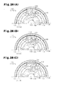
Patent Document 1 discloses a seat reclining device equipped with a locking mechanism and a memory mechanism. Thelocking mechanism 100 is made up of afirst member 101, a second member (not shown), a plurality oflocking members 103, acam 104, and a spring (not shown), as shown inFig. 26(A) . Thefirst member 101 is attached to one of the seat cushion and the seat back, and hasinternal gear 106 around anoperation shaft 105. The second member is attached to the other one of the seat cushion and the seat back, and rotates around theoperation shaft 105 relative to thefirst member 101. Thelocking members 103 are attached to the second member and each haveexternal teeth 107. Thecam 104 is connected to theoperation shaft 105 and urged counterclockwise inFig. 26(A) by a spring. When thecam 104 rotates counterclockwise by the urging force, thelocking members 103 are each pressed radially outward by thecam 104. Theexternal teeth 107 thereby mesh with theinternal gear 106, so that the seat back is locked. Operating a first operation lever rotates thecam 104 clockwise with theoperation shaft 105. Thelocking members 103 are each moved radially inward by thecam 104. Theexternal teeth 107 thereby disengage from theinternal gear 106, so that the seat back is unlocked. There are two unlocked states of the seat: in one state, the seat back is allowed to tilt without an angular position being remembered by thememory mechanism 110, and in the other state, the seat back is allowed to tilt with an angular position being remembered by thememory mechanism 110. - The
memory mechanism 110 includes ahousing recess 111,engagement portions 112, and amemory plate 113. Oneengagement portion 112 each is provided on eachlocking member 103. Thehousing recess 111 is provided to thefirst member 101 and formed in a cylindrical shape. Theengagement portions 112 each protrude from thelocking members 103 along theoperation shaft 105. Thememory plate 113 is formed in an annular shape that is cut at one point. Thememory plate 113 is housed in thehousing recess 111 while being reduced in diameter. Anengagement receiving portion 114, formed as a recess, is provided in the inner circumferential surface 1138 of thememory plate 113. Theengagement portions 112 engage with and disengage from theengagement receiving portion 114. - To tilt the locked seat back to a desired angle, the first operation lever is operated to rotate the
operation shaft 105. In this case, the first operation lever is moved by an angle necessary for unlocking the seat back so that it can tilt, without its angular position being remembered by thememory mechanism 110. At this time, thecam 104 is rotated clockwise inFig. 26(A) by a certain angle with theoperation shaft 105. The rotation of thecam 104 slightly moves thelocking members 103 radially inward, as shown inFig. 26(B) . As eachlocking member 103 moves, theexternal teeth 107 disengage from theinternal gear 106. The seat back is thus unlocked. Theengagement portion 112 is half engaged with theengagement receiving portion 114. When the seat back is tilted forward in this state, thelocking members 103 each rotate with thememory plate 113 relative to the housing recess 111. At this time, the outercircumferential surface 113A of thememory plate 113 slides on the innercircumferential surface 111 A of the housing recess 111. When the first operation lever is returned to its initial position, thecam 104 presses each of thelocking members 103 radially outward by the urging force of the spring. Theexternal teeth 107 thereby mesh with theinternal gear 106, so that the seat back is locked. - To tilt the locked seat back forward, it is unlocked and allowed to tilt with its angular position being remembered by the
memory mechanism 110. In this case, a second operation lever provided separately from the first operation lever is operated to rotate theoperation shaft 105 more largely than when unlocking and allowing the seat back to tilt without an angular position being remembered by thememory mechanism 110. Thereby, thecam 104 rotates largely with theoperation shaft 105 clockwise inFig. 26(B) . The rotation of thecam 104 moves each of thelocking members 103 radially inward. Eachlocking member 103 moves more than when the first operation lever is operated. As eachlocking member 103 moves, theengagement portion 112 disengages from theengagement receiving portion 114. When the seat back is tilted forward in this state, thememory plate 113 remains retained by the housing recess 111 by the friction between thememory plate 113 and the housing recess 111, as shown inFig. 26(C) . Theengagement portion 112 slides on the innercircumferential surface 113B of thememory plate 113 counterclockwise. Since thememory plate 113 does not rotate relative to the housing recess 111 at this time, theengagement receiving portion 114 stays in position relative to thefirst member 101. In this way, the angular position of the seat back where it is located immediately before being tilted forward is remembered by thememory plate 113. - The seat back that has been tilted forward is then pulled back against the urging force of the forward tilt urging means. The
engagement portion 112 then slides on the innercircumferential surface 113B of thememory plate 113 clockwise inFig. 26(C) , with thememory plate 113 retained by thehousing recess 111. When the seat back comes to the angular position where it is located immediately before being tilted forward, theengagement portion 112 meets theengagement receiving portion 114, and eachlocking member 103 is pressed radially outward by thecam 104. Theexternal teeth 107 thereby mesh with theinternal gear 106, so that the seat back is locked. The angular position of the seat back where it is located immediately before being tilted forward can be remembered by such a simple structure, so that the seat back can be reset to the remembered angular position when it is pulled back up after being tilted forward. - However, in the seat reclining device described in
Patent Document 1, when adjusting the locked seat back to a desired angular position, theengagement portion 112 is half engaged with theengagement receiving portion 114 as shown inFig. 26(B) . Thelocking members 103 rotate with thememory plate 113 relative to the housing recess 111 in this state. Thememory plate 113 that has been reduced in diameter in thehousing recess 111 is pressed against the innercircumferential surface 111 A of the housing recess 111. Therefore, when theengagement portion 112 presses theengagement receiving portion 114 to enlarge the cut portion of thememory plate 113, the friction between the outercircumferential surface 113A of thememory plate 113 and the innercircumferential surface 111 A of thehousing recess 111 is increased. The sliding resistance of thememory plate 113 becomes accordingly large, which makes it harder to rotate thememory plate 113 relative to thehousing recess 111. This consequently increases the operation load when adjusting the angular position of the seat back. - It is conceivable to reduce the surface pressure between the outer
circumferential surface 113A of thememory plate 113 and the innercircumferential surface 111 A of thehousing recess 111 to reduce the sliding resistance of thememory plate 113. With this approach, however, if adopted, thememory plate 113 could no longer be retained by thehousing recess 111 in an unlocked state where the seat back is allowed to tilt with an angular position of the seat back being remembered. Thememory plate 113 would therefore rotate with the lockingmembers 103 and could not fully exhibit its memory function. - Patent Document 1: Japanese Laid-Open Patent Publication No.
11-70027 - An objective of the present invention is to provide a seat reclining device and a seat device in which a memory plate is made irrotational in an unlocked state where the seat back is allowed to tilt with an angular position being remembered, and in which operation load is reduced in an unlocked state where the seat back is allowed to tilt without an angular position being remembered.
- To achieve the foregoing objective and in accordance with a first aspect of the present invention, a seat reclining device including a locking mechanism and a memory mechanism is provided. The locking mechanism switches a seat back between a locked state, in which the seat back is restricted from tilting relative to a seat cushion, and an unlocked state, in which the seat back is allowed to tilt, in accordance with a rotating movement of an operation shaft. The memory mechanism stores an angular position of the seat back where it is located immediately before being unlocked. The seat back, once unlocked, is locked only when it is tilted to the angular position that has been remembered. The locking mechanism includes a first member, a second member, and a plurality of locking members. The first member is attached to one of the seat cushion and the seat back and has an internal gear around the operation shaft. The second member is attached to the other one of the seat cushion and the seat back and rotational around the operation shaft relative to the first member. The locking members are each attached to the second member and have external teeth facing the internal gear. The seat back is locked when the locking members are each pressed radially outward so that the external teeth mesh with the internal gear. The seat back is unlocked when the operation shaft is rotated thereby to move each of the locking members radially inward so that the external teeth disengage from the internal gear. The memory mechanism includes an engagement portion, a housing recess, a memory plate, and a pair of engagement receiving portions. The engagement portion is provided to adjacent pair of locking members. The housing recess is formed in a cylindrical shape in the first member. The memory plate is formed in an annular shape that is cut at one point. The memory plate is housed in the housing recess while being reduced in diameter with the cut portion being located between the engagement portions. Each of the pair of engagement receiving portions is provided to the memory plate and adjacent to and between the engagement portions. The engagement portions engage with and disengage from the engagement receiving portions as the locking members move in the radial direction. The unlocked state includes: an unlocked state in which the engagement receiving portions are pressed circumferentially with the engagement portions half engaged with the engagement receiving portions and the memory plate rotates together with the locking members relative to the housing recess, so that the seat back is allowed to tilt without the angular position being remembered; and an unlocked state in which the engagement portion rides over the engagement receiving portion and slides on an inner circumferential surface of the engagement receiving portion with the memory plate being made irrotational relative to the housing recess, so that the seat back is allowed to tilt with the angular position being stored.
- With the above configuration, the locking members attached to the second member are each pressed radially outward. With the external teeth of the locking members meshing with the internal gear of the first member, the seat back is locked. Thereby, the seat back is restricted from tilting relative to the seat cushion. To unlock the seat back, the operation shaft is rotated, to move each of the locking members radially inward. This disengages the external teeth from the internal gear so that the first member and the second member can rotate relative to each other. Thus the seat back is allowed to tilt relative to the seat cushion. There is one unlocked state, in which the seat back is allowed to tilt without an angular position being remembered, and another unlocked state where the seat back is allowed to tilt with an angular position being remembered.
- In the former unlocked state, the engagement portions of the locking members half engage with the adjacent engagement receiving portions. Since the engagement receiving portions are pressed by the engagement portions in this state, the memory plate rotates with the locking members relative to the housing recess. The cut portion of the memory plate is positioned between the engagement portions of the respective locking members. The pair of engagement receiving portions of the memory plate are located between the engagement portions and adjacent to the respective engagement portions. Namely, the engagement receiving portions are each located between the cut portion and the engagement portion. Therefore, when one of the engagement portions presses the adjacent engagement receiving portion, the other engagement portion does not press the adjacent engagement receiving portion. The one engagement portion presses the engagement receiving portion circumferentially in a direction in which the space of the cut portion of the memory plate is reduced. Contrarily, when the other engagement portion presses the adjacent engagement receiving portion, the one engagement portion does not press the adjacent engagement receiving portion. The other engagement portion presses the engagement receiving portion circumferentially in a direction in which the space of the cut portion of the memory plate is reduced. As the space of the cut portion is reduced, the memory plate is reduced in diameter when the seat back is tilted. Therefore, since the friction between the outer circumferential surface of the memory plate and the inner circumferential surface of the housing recess is reduced, the seat back can be adjusted to a desired inclination angle with an appropriate operation load.
- In the latter unlocked state, one of the engagement portions rides over the corresponding engagement receiving portion. With the memory plate being made irrotational relative to the housing recess, one of the engagement portions slides on the inner circumferential surface of the engagement receiving portion. In this case, unlike the former unlocked stated, the one engagement receiving portion is not pressed circumferentially by the corresponding engagement portion, so that the memory plate is not reduced in diameter. The memory plate is housed in the housing recess while being reduced in diameter. Since the memory plate is in pressure contact with the inner circumferential surface of the housing recess, there is large friction between the outer circumferential surface of the memory plate and the inner circumferential surface of the housing recess. Accordingly, the memory plate is made irrotational relative to the housing recess and can exhibit its intended memory function.
- In the above described seat reclining device, the housing recess is preferably adjacent to a meshing part of the internal gear and the external teeth on an opposite side from the second member, and the housing recess preferably supports an outer circumferential surface of the memory plate with an inner circumferential surface having the same diameter as the diameter of the addendum circle of the internal gear or with tooth tops of the internal gear.
- With the above configuration, the housing recess is adjacent to the meshed portion between the internal gear and the external teeth on the opposite side from the second member. The memory plate is housed in the housing recess to be slidable in the circumferential direction. The locking members having external teeth facing the internal gear are arranged between the memory plate and the second member. As the locking members are each moved radially, their external teeth are made to mesh with or disengage from the internal gear. To allow easy movement of the locking members, there are gaps around each locking member. The memory plate in the housing recess can easily come off of the housing recess by its restoring force and move into the gap, which may adversely affect the operation of the locking mechanism or the memory mechanism. In this respect, according to the present invention, the housing recess supports the outer circumferential surface of the memory plate with the inner circumferential surface having the same diameter as the diameter of the addendum circle of the internal gear, or with the tooth tops of the internal gear. Therefore, the gap around each locking member can be minimized as much as possible. Accordingly, even if the memory plate comes off of the housing recess by its own restoring force, it can hardly go into such a gap.
- In the above described seat reclining device, the engagement receiving portions preferably protrude radially inward from different positions on the memory plate. The memory plate preferably has a radial thickness set identical in a portion between the engagement receiving portions and in the engagement receiving portion of the memory plate, and the engagement receiving portion is preferably a portion on which the engagement portion slides in a state in which the seat back is unlocked and allowed to tilt with the angular position being remembered.
- The portion on which the engagement portion slides when unlocking the seat back so that it can be tilted with an angular position being remembered, is an inner circumferential surface of the engagement receiving portion. The engagement receiving portion is positioned inner than the portion between the engagement receiving portions of the memory plate. If the outer diameter of the memory plate were the same all around, the thickness would be larger in the engagement receiving portion than in other portions. The memory plate may then be distorted when it is flexed and assembled into the housing recess, and may resist being fitted into the housing recess. In this respect, according to the present invention, the thickness of the memory plate is set the same in the engagement receiving portion and in other portions. Therefore, the memory plate will not be distorted when it is flexed and assembled into the housing recess, and can easily be fitted into the housing recess. The memory plate will not be distorted, either, when the memory plate rotates with the locking members by the pressure applied circumferentially from the engagement portion to the engagement receiving portion, but will be reduced in diameter, with its uniform annular shape maintained. Thereby, the friction applied between the outer circumferential surface of the memory plate and the inner circumferential surface of the housing recess can be made uniform.
- In the above described seat reclining device, it is preferable that: the seat reclining device be applied to a seat device having a first operation lever, a second operation lever, and a seat sliding device; the first operation lever be operated to rotate the operation shaft to unlock and allow the seat back to tilt without the angular position being remembered; the second operation lever be operated to rotate the operation shaft to unlock and allow the seat back to tilt without the angular position being remembered, and to rotate the operation shaft more largely than for the unlocking, thereby to unlock and allow the seat back to tilt with the angular position being remembered; the seat back have a tilting range divided into a seating region, in which the inclination angle thereof is adjusted, and a forward folding region set forward of the seating region; the seat back be tilted relative to the seat cushion within the tilting range around the operation shaft, which is rotated by operating the first operation lever or the second operation lever; and the seat sliding device restrict sliding movement of the seat cushion at least in the seating region, and cancels the restriction of the sliding movement of the seat cushion in coordination with a tilting movement of the seat back from the seating region into the forward folding region after being unlocked by the locking mechanism upon the second operation lever being operated. The seat reclining device preferably further includes. During operation of the first operation lever, the switch limit mechanism preferably allows switching between locking and unlocking of the seat back by the locking mechanism only when the seat back is tilted within the seating region.
- The seat sliding device restricts the sliding movement of the seat cushion at least when the seat back is tilted in the seating region. When the second operation lever is operated to unlock the locking mechanism, after which the seat back is tilted forward from the seating region into the forward folding region, the seat sliding device cancels the restriction of the sliding movement, in coordination with the forward tilting of the seat back. Thereby the seat cushion is allowed to slide.
- With a common seat reclining device, the seat back can be locked or unlocked by the locking mechanism when the first operation lever is operated, wherever angular position in the tilting range the seat back is located. In this case, there is a possibility that, in adjusting the inclination angle of the seat back by operating the first operation lever, the seat back may be accidentally tilted in the forward folding region, whereupon the restriction of the sliding movement may be canceled. In this respect, according to the present invention, the switch limit mechanism limits the locking mechanism to lock or unlock the seat back when the first operation lever is operated, only when the seat back is tilted within the seating region. Therefore, even with the first operation lever being operated, the switching between the locked and unlocked states is disabled in the forward folding region. As a result, when adjusting the inclination angle of the seat back by operating the first operation lever, the seat back will not be accidentally tilted in the forward folding region. The seat sliding device, therefore, will not cancel the restriction of the sliding movement.
- In the above described seat reclining device. The switch limit mechanism preferably includes a rotation restricting portion provided in the first member, and the rotation restricting portion preferably has an inner circumferential surface with the same diameter as that of the inner circumferential surface of the engagement receiving portion, on which the engagement portion slides. When the first operation lever is operated, the engagement portion that is half engaged is preferably abutted on the rotation restricting portion so that the memory plate and the locking members are restricted from rotating, whereby the seat back is stopped from tilting from the seating region into the forward folding region. When the second operation lever is operated, the engagement portion preferably rides over the engagement receiving portion and the rotation restricting portion and slides on the inner circumferential surface of the engagement receiving portion, whereby the seat back tilts from the seating region into the forward folding region.
- With the above configuration, when the first operation lever is operated to tilt the seat back from the seating region into the forward folding region, the engagement portion that is half engaged with the engagement receiving portion abuts on the rotation restricting portion. This restricts the memory plate and the locking members from rotating, whereby the first member is restricted from rotating relative to the second member. The seat back is thus stopped from being tilted into the forward folding region. On the other hand, when the second operation lever is operated to tilt the seat back from the seating region into the forward folding region, the engagement portion rides over the engagement receiving portion and the rotation restricting portion, and slides on the inner circumferential surface of the engagement receiving portion. The locking members are thereby allowed to rotate, so that the second member is allowed to rotate relative to the first member, whereby the seat back is allowed to tilt from the seating region into the forward folding region.
- To achieve the foregoing objective and in accordance with a second aspect of the present invention, a seat device having the above described seat reclining device is provided. The seat reclining device is provided on either side of the seat device, and the operation shafts of the respective seat reclining devices are integrally rotational.
- With the above configuration, the seat reclining devices provided on both sides of the seat device have the same locking mechanism and memory mechanism. The operation shafts, which make the locking mechanisms and memory mechanisms of the respective seat reclining devices work, are connected to be integrally rotational. Therefore, the locking mechanisms of both seat reclining devices work in synchronism, and so do the memory mechanisms, when the operation shafts are rotated.
- In the above described seat device, the first operation lever or the second operation lever is preferably operated to rotate the operation shafts to unlock and allow the seat back to tilt without the angular position being remembered, and the second operation lever is preferably operated to rotate the operation shafts more largely than when unlocking and allowing the seat back to tilt without the angular position being remembered, whereby the seat back is unlocked and allowed to tilt with the angular position being remembered. The seat device further includes. When the second operation lever is operated to unlock and allow the seat back to tilt with the angular position being stored, the lost motion mechanism preferably puts the first operation lever in a non-operational state without transmitting a movement of the second operation lever to the first operation lever.
- The rotation amount of the operation shafts rotated by operating the second operation lever when unlocking and allowing the seat back to tilt with an angular position being remembered is greater than the rotation amount of the operation shafts rotated by the first operation lever or the second operation lever when unlocking and allowing the seat back to tilt without an angular position being remembered. In this respect, according to the present invention, when the second operation lever is operated as in the former case, the lost motion mechanism does not transmit the movement of the second operation lever to the first operation lever and puts the first operation lever in a non-operational state. Thereby, the difference in the amount of rotation of the operation shafts between the former unlocked state and the latter unlocked state can be absorbed.
- In the above described seat device, the first operation lever is preferably supported to be rotational relative to the operation shafts, and the second operation lever is connected to the operation shafts. The lost motion mechanism preferably includes: a link member connected to the operation shafts; an oblong hole that is provided to one of the first operation lever and the link member and has an arcuate shape having a center coinciding with the operation shaft; and a pin that is provided to the other one of the first operation lever and the link member and is received in the oblong hole. When the second operation lever is operated to unlock and allow the seat back to tilt with the angular position being remembered, the pin is preferably allowed to move within the oblong hole so that the movement of the second operation lever is not transmitted to the first operation lever and the first operation lever is put in a non-operational state.
- With the above configuration, when the second operation lever is operated to unlock and allow the seat back to tilt with the angular position being remembered, the pin is allowed to move within the oblong hole so that the movement of the second operation lever is not transmitted to the first operation lever and the first operation lever is put in a non-operational state.
- To achieve the foregoing objective and in accordance with a third aspect of the present invention, a vehicle seat device is provided that includes a seat back, a locking mechanism, a seat sliding device, and a switch limit mechanism. The seat back has a tilting range divided into a seating region, in which an inclination angle thereof is adjusted, and a forward folding region set forward of the seating region. The seat back is tilted within the tilting range around an operation shaft relative to the seat cushion. When a first operation lever or a second operation lever is operated to rotate the operation shaft, the locking mechanism switches the seat back between a locked state, in which the seat back is restricted from tilting relative to the seat cushion, and an unlocked state, in which the seat back is allowed to tilt. The seat cushion is restricted from sliding at least in the seating region. The restriction of the sliding movement of the seat cushion is canceled in coordination with a tilting movement of the seat back from the seating region into the forward folding region after being unlocked by the locking mechanism, upon the second operation lever being operated. During operation of the first operation lever, the switch limit mechanism allows switching between locking and unlocking of the seat back by the locking mechanism only when the seat back is tilted within the seating region.
- In the above described vehicle seat, the locking mechanism preferably includes a first member, a second member, and a plurality of locking members, the first member is preferably attached to one of the seat cushion and the seat back and has an internal gear around the operation shaft, and the second member is preferably attached to the other one of the seat cushion and the seat back and rotational around the operation shaft relative to the first member. Further, the locking members are preferably each attached to the second member and have external teeth facing the internal gear. The seat back is preferably locked when the locking members are each pressed radially outward so that the external teeth mesh with the internal gear, and the seat back is preferably unlocked when the operation shaft is rotated thereby to move each of the locking members radially inward so that the external teeth disengage from the internal gear.
- The above described vehicle seat device preferably includes a memory mechanism that remembers an angular position of the seat back where it is located immediately before being unlocked. The seat back, once unlocked, is preferably locked only when it is tilted to the angular position that has been remembered, and the memory mechanism preferably works when the second operation lever is operated to rotate the operation shaft.
- With the above configuration, switching between the locked and unlocked states by the locking mechanism is performed as well as the memory mechanism is made to work when the operation shaft is rotated by operating the second operation lever. In the latter case, the angular position of the seat back where it is located immediately before being unlocked is remembered, and the unlocked seat back is locked by the locking mechanism only when it is tilted to the remembered angular position.
- In the above described vehicle seat device, it is preferable that: the memory mechanism include a housing recess, a memory plate, and an engagement portion; the housing recess be formed in a cylindrical shape in the first member; the memory plate be formed in an annular shape that is cut at one point; the memory plate be housed in the housing recess while being reduced in diameter; the memory plate include a pair of engagement receiving portions at different positions; and the engagement portion be provided to each of a pair of locking members, and engages with and disengages from the engagement receiving portions as the locking members move in the radial direction. The unlocked state preferably include: an unlocked state in which the engagement receiving portions are pressed circumferentially with the engagement portions half engaged with the engagement receiving portions and the memory plate rotates together with the locking members relative to the housing recess, so that the seat back is allowed to tilt without the angular position being remembered; and an unlocked state in which the engagement portion going over the engagement receiving portion and slides on an inner circumferential surface of the memory plate with the memory plate being made irrotational relative to the housing recess, so that the seat back is allowed to tilt with the angular position being stored.
- In the above described vehicle seat device, the switch limit mechanism preferably includes a rotation restricting portion provided in the first member, and the rotation restricting portion preferably has an inner circumferential surface with the same diameter as that of the inner circumferential surface of the memory plate on which the engagement portion slides. When the first operation lever is operated, the engagement portion that is half engaged is preferably abutted on the rotation restricting portion so that the memory plate and the locking members are restricted from rotating, whereby the seat back is stopped from tilting from the seating region into the forward folding region. When the second operation lever is operated, the engagement portion preferably rides over the engagement receiving portion and the rotation restricting portion and slides on the inner circumferential surface of the memory plate, whereby the seat back is allowed to tilt from the seating region into the forward folding region.
- In the above described the vehicle seat device, the switch limit mechanism preferably includes: an abutment receiving portion that is provided to the seat back and is displaced with a tilting movement of the seat back; a movable stopper tiltably supported by a shaft to tilt between an abutting position, where the movable stopper is abutted on the abutment receiving portion to restrict tilting of the seat back, and a non-abutting position, where the movable stopper is retracted from the abutting position; a link member that is connected to the operation shaft and capable of transmitting, to the movable stopper, rotation of the operation shaft upon the first operation lever or the second operation lever being operated; and rotation transmission control means. The rotation transmission control means: does not transmit rotating movement of the link member to the movable stopper when the first operation lever or the second operation lever is operated in order to rotate the operation shaft by an angle for unlocking and allowing the seat back to tilt without an angular position being remembered; positions the movable stopper at the abutting position to restrict the seat back from being tilted forward, whereby switching between the locked and unlocked states by the locking mechanism is allowed to be performed only when the seat back is tilted within the seating region; transmits rotating movement of the link member to the movable stopper when the second operation lever is operated more largely to rotate the operation shaft than when unlocking and allowing the seat back to tilt without an angular position being remembered; and retracts the movable stopper to the non-abutting position to cancel the restriction of the forward tilting of the seat back, whereby the seat back is allowed to tilt from the seating region into the forward folding region.
- With the above configuration, the operation shaft can be rotated by an angle necessary for unlocking and allowing the seat back to tilt without an angular position being remembered, by operating the first operation lever or the second operation lever. At this time, the rotation transmission control means can stop the rotating movement of the link member from being transmitted to the movable stopper. Thereby, with the movable stopper being located at the abutting position and abutting on the abutment receiving portion, the seat back is restricted from tilting forward. Accordingly, the switching between the locked and unlocked states by the locking mechanism can be limited to be performed only when the seat back is tilted within the seating region. The operation shaft can be rotated more largely than when unlocking and allowing the seat back to tilt without an angular position being remembered, by operating the second operation lever. At this time, the rotating movement of the link member is transmitted to the movable stopper, and the movable stopper retracts to the non-abutting position. This cancels the restriction of the forward tilting of the seat back, so that the seat back can be tilted forward from the seating region into the forward folding region.
- In the above described vehicle seat device the rotation transmission control means preferably includes a cam hole formed in one of the movable stopper and the link member, and a pin provided to the other one of the movable stopper and the link member and received in the cam hole.
- In this case, when the first operation lever is operated, the link member rotates with the operation shaft, and the position of the pin inside the cam hole is changed around the operation shaft. The rotating movement of the link member at this time is not transmitted to the movable stopper via the pin and the cam hole. Thereby, with the movable stopper being located at the abutting position and abutting on the abutment receiving portion, the seat back is restricted from tilting forward. The operation shaft can be rotated more largely than when unlocking and allowing the seat back to tilt without an angular position being remembered, by operating the second operation lever. At this time, the link member rotates with the operation shaft more largely than when the first operation lever is operated. Therefore, the rotating movement of the link member is transmitted to the movable stopper via the pin and the cam hole.
-
-
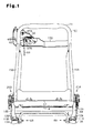
Fig. 1 is a front view illustrating the framework of a vehicle seat device according to a first embodiment of the present invention; -
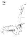
Fig. 2 is a side view illustrating the framework of the vehicle seat device; -
Fig. 3 is a side view illustrating the tilting range of the seat back; -
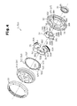
Fig. 4 is an exploded perspective view of a seat reclining device; -
Fig. 5 is an exploded perspective view of the seat reclining device; -
Fig. 6 is a front view of the seat reclining device; -
Fig. 7 is a cross-sectional view taken along line 7-7 ofFig. 6 ; -
Fig. 8 is an enlarged partial cross-sectional view illustrating part ofFig. 7 ; -
Fig. 9 is a partial cross-sectional view illustrating a comparative example of a seat reclining device; -
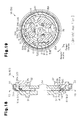
Fig. 10 is a cross-sectional view taken along line 10-10 ofFig. 7 ; -
Fig. 11 is a cross-sectional view taken along line 11-11 ofFig. 7 ; -
Fig. 12 is a rear view of the seat reclining device ofFig. 7 viewed in the direction of arrow D; -
Fig. 13 is a rear view of a memory plate in the seat reclining device ofFig. 7 viewed in the direction of arrow D; -
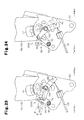
Fig. 14 is a partial side view illustrating the vicinity of an operation shaft on the right side of the vehicle seat device; -
Fig. 15 is a partial side view of the same when the first operation lever is moved to a release position; -
Fig. 16 is a partial side view illustrating the vicinity of an operation shaft on the left side of the vehicle seat device; -
Fig. 17 is a partial side view of the same when the second operation lever is pulled up; -
Fig. 18 is a cross-sectional view taken along line 18-18 ofFig. 6 ; -
Fig. 19 is a cross-sectional view taken along line 19-19 ofFig. 18 ; -
Fig. 20 is a cross-sectional view illustrating a seat reclining device that has unlocked the seat back so that it can be tilted without an angular position being remembered; -
Fig. 21 is a cross-sectional view illustrating the seat reclining device that has unlocked the seat back so that it can be tilted with an angular position being remembered; -
Fig. 22 is a cross-sectional view illustrating the seat reclining device when the seat back is tilted forward; -
Fig. 23 is a partial side view illustrating a switch limit mechanism according to a second embodiment of the present invention; -
Fig. 24 is a partial side view illustrating the switch limit mechanism when the second operation lever is operated; -
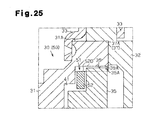
Fig. 25 is a partial cross-sectional view illustrating another example of a housing recess; -
Fig. 26(A) is a partial cross-sectional view illustrating a conventional seat reclining device; -
Fig. 26(B) is a partial cross-sectional view illustrating the conventional seat reclining device; and -
Fig. 26(C) is a partial cross-sectional view illustrating the conventional seat reclining device. - Hereinafter, a first embodiment of the present invention in which the invention is embodied as a vehicle seat device equipped with a walk-in system will be described with reference to
Figs. 1 to 22 . In the following description, the forward moving direction of the vehicle will be referred to as front or forward, the backward moving direction of the vehicle as rear or backward, the height direction of the vehicle as up and down direction, and the vehicle width direction when the vehicle is moving forward as left-right direction. The vehicle here is a two-door one-box car with a relatively small space for getting in and out. - As shown in
Figs. 1 and2 , the vehicle seat device includes a pair oflower rails upper rails seat cushion frame 14, and a seat backframe 15. The lower rails 11 A and 11B have their longitudinal direction oriented in the front to back direction, and are secured to the vehicle floor (not shown) withbrackets upper rails lower rails - The
seat cushion frame 14 forms the framework of a seat cushion, on which a passenger sits. Theseat cushion frame 14 includes a pair oflower arms coupling rod 14C connecting the rear ends of bothlower arms support brackets Figs. 14 and 15 ) fixedly attached to the rear ends of the respectivelower arms lower arms upper rails - The seat back
frame 15 is rotationally coupled to the rear ends of thelower arms frame 15 forms the framework of the seat back that supports the upper body of the passenger from behind. The seat backframe 15 includes a pair ofside frames upper pipe 15C connecting the upper ends of bothside frames cross member 15D arranged between the ends of theupper pipe 15C. - The tilting range of the seat back
frame 15 is divided into a seating region and a forward folding region, as shown inFig. 3 . The seat backframe 15 is tiltable to theseat cushion frame 14 aroundoperation shafts frame 15 indicated by solid lines inFig. 3 represents the angular position of the seat back when a passenger is seated (hereinafter referred to as a neutral position). The forward folding region is from the upright position to a forward folding position, where the seat back is tilted forward. - A walk-in system is used when seating on a second-row seat through a door of a two-door car, or when seating on a third-row seat through a rear door of a one-box car. More specifically, the walk-in system works to tilt the seat back forward as well as to slide the seat cushion forward in order to achieve more space for access to the seat.
- The vehicle seat device is equipped with a pair of
seat reclining devices seat reclining devices seat reclining device 20A is arranged between thesupport bracket 14D and theside frame 15A. Theseat reclining device 20B is arranged between thesupport bracket 14E and theside frame 15B. Theseat reclining devices locking mechanism 30 and amemory mechanism 50 shown inFig. 4 . - The spiral springs urges the seat back forward. The spiral springs are made of a wire member formed in a spiral shape. One end of the spiral springs is retained by the
seat cushion frame 14, while the other end is retained by the seat backframe 15. Thelocking mechanism 30 switches the seat back between a locked state, in which the seat back is restricted from tilting relative to the seat cushion, and an unlocked state, in which the seat back is allowed to tilt. Theoperation shaft 16A of the left-sideseat reclining device 20A and theoperation shaft 16B of the right-sideseat reclining device 20B are coupled to each other by acommon rod 22, as shown inFig. 1 . - The
locking mechanism 30 includes, as shown inFigs. 4 to 7 , afirst member 31 attached to theside frame second member 32 attached to thesupport bracket holder 33 mounted to thefirst member 31 and thesecond member 32. Thelocking mechanism 30 further includes acam 34, threepawls 35 as locking members, and aspiral spring 36. Thecam 34 and thepawls 35 are located between thefirst member 31 and thesecond member 32. Thespiral spring 36 is located on the opposite side of thesecond member 32 from thecam 34. Thesecond member 32 is formed in an annular shape by a half blanking process. Thesecond member 32 is secured to theseat cushion frame 14 via thesupport bracket Fig. 7 . - On the opposite side of the
second member 32 from thesupport bracket circular recess 37. In therecess 37 are formed threeguide walls 38 at predetermined angular intervals, as shown inFig. 4 ,Figs. 10, and 11 . Eachguide wall 38 protrudes a predetermined height from the bottom wall of thesecond member 32. Side faces 38A ofadjacent guide walls 38 are parallel to each other and extend straight in the radial direction. Radially extending guide grooves are thus formed between adjacent side faces 38A. The guide grooves guide the radial movement of thepawls 35. Thefirst member 31 is formed in an annular shape by a half blanking process, as shown inFigs. 5 and7 . The outer diameter of thefirst member 31 is the same as the inner diameter of therecess 37. Thefirst member 31 is secured to the seat backframe 15 via theside frame - The
first member 31 is fitted in thesecond member 32 with its outercircumferential surface 31 A sliding on the innercircumferential surface 37A of thesecond member 32. The seat backframe 15 is rotationally connected to theseat cushion frame 14 via thefirst members 31 and thesecond members 32. Thefirst member 31 rotates counterclockwise inFig. 10 when tilting the seat backframe 15 forward. Thefirst member 31 rotates clockwise inFig. 10 when tilting the seat backframe 15 backward. - On the opposite side of the
first member 31 from theside frame 15 is formed afirst recess 39, which is circular and concentric with thesecond member 32. Thefirst recess 39 has aninternal gear 39A formed on its inner circumferential surface. When thefirst member 31 is fitted in thesecond member 32, theinternal gear 39A is directed toward the guide grooves. In thefirst recess 39 is formed asecond recess 41, which is concentric with thefirst recess 39, circular, and smaller in diameter than thefirst recess 39. Thefirst recess 39 and thesecond recess 41, together with therecess 37, form a space for housing thecam 34 and thepawls 35. Theholder 33 is formed in an annular shape. Theholder 33 is fitted on thefirst member 31 and thesecond member 32 over the peripheries of the first andsecond members holder 33 supports thefirst member 31 and thesecond member 32 to be relatively rotational and not to come apart in the axial direction. - The
cam 34 has threecam profile portions 34A around the rim at predetermined angular intervals, as shown inFigs. 4 and5 . Thecam profile portions 34A thus form acam surface 34B with their outer surfaces. Eachcam profile portion 34A has anaxially protruding protrusion 34C. Thecam 34 is encased between thesecond member 32 and thefirst member 31 to be rotational relative to thesecond member 32. Thecam 34 rotates clockwise inFig. 10 or counterclockwise inFig. 11 with theoperation shaft first operation lever 61 or thesecond operation lever 62. - As shown in
Figs. 4 ,5 , and12 , the outer end of thespiral spring 36 is retained by thesecond member 32, while the inner end thereof is retained by thecam 34. Thecam 34 rotates counterclockwise inFig. 10 or clockwise inFig. 11 by the urging force of thespiral spring 36 when thefirst operation lever 61 or thesecond operation lever 62 is released from an operating force. As thecam 34 rotates,external teeth 35A of thepawls 35 mesh with theinternal gear 39A of thefirst member 31, whereby the seat back is locked. The outer end of thespiral spring 36 may be retained by thesupport bracket seat cushion frame 14 instead of thesecond member 32. - The
pawls 35 are each formed in a quadrate, planar shape, as shown inFigs. 4 ,5 ,10, and 11 . Thepawls 35 each have a width somewhat smaller than the width of the guide grooves, i.e., distance betweenadjacent guide walls 38. Onepawl 35 each is arranged in the guide groove. Eachpawl 35 is radially guided, as they slide on the side faces 38A of theguide walls 38 on both sides.External teeth 35A to mesh with theinternal gear 39A of thefirst member 31 are formed at the outer end of eachpawl 35. Acam hole 35B is formed at the inner end of eachpawl 35. Eachcam hole 35B is inclined relative to the inner end face of thepawl 35. Theprotrusions 34C of thecam 34 are fitted in the cam holes 35B of therespective pawls 35. Thereby thepawls 35 are each engaged with thecam 34. - Each
pawl 35 has a stepped portion between itsexternal teeth 35A and thecam hole 35B. The inner end face of the stepped portion forms apawl cam surface 35C. Thepawl cam surface 35C extends across the side face of thepawl 35 and is inclined relative to the pitch circle of theexternal teeth 35A. Thepawl 35 is engaged with thecam 34 by thepawl cam surface 35C abutting on thecam surface 34B. - When the
cam 34 is rotated clockwise inFig. 10 together with theoperation shaft protrusions 34C of thecam 34. Accordingly, thepawls 35 each move radially inward along the guide grooves. This disengages theexternal teeth 35A of thepawls 35 from theinternal gear 39A of thefirst member 31. The seat back is thus unlocked, as thefirst member 31 is made rotational relative to thesecond member 32. On the other hand, when thecam 34 rotates counterclockwise inFig. 10 , the pawl cam surfaces 35C are pressed by thecam surface 34B. Accordingly, thepawls 35 each move radially outward along the guide grooves. This causes theexternal teeth 35A of thepawls 35 to mesh with theinternal gear 39A of thefirst member 31. The seat back is thus locked, as thefirst member 31 is not allowed to rotate relative to thesecond member 32. - A
memory mechanism 50 remembers the angular position of the locked seat back where it is located immediately before being unlocked. Thememory mechanism 50 locks the seat back only when it is tilted to the remembered angular position. Thememory mechanism 50 includesengagement portions housing recess 51, amemory plate 52, and a pair ofengagement receiving portions engagement portions pawls 35. - As shown in
Fig. 10 , theengagement portions pawls 35. Thepawls 35 have a steppedportion 54 on the opposite side from the pawl cam surfaces 35C, as shown inFigs. 4 and5 . The steppedportion 54 is positioned between theexternal teeth 35A and thecam hole 35B. Theengagement portions portion 54 of eachpawl 35. Theengagement portion 53A protrudes radially outward from the steppedportion 54 much more than theengagement portion 53B. - As shown in
Fig. 8 , thehousing recess 51 is provided on the opposite side of the meshing part of theinternal gear 39A and theexternal teeth 35A from thesecond member 32. Thehousing recess 51 is provided on the opposite side of thefirst recess 39 from thesecond member 32. Thehousing recess 51 is concentric with thefirst recess 39 and has an innercircumferential surface 51 A with the same diameter as the diameter of the addendum circle of theinternal gear 39A. - The
memory plate 52 is formed in an annular shape that is cut at one point, as shown inFigs. 10 and13 . Thememory plate 52 is therefore flexibly deformable in a radial direction. The cut portion S of thememory plate 52 is positioned between theengagement portions memory plate 52 is housed in thehousing recess 51 while being reduced in diameter. Thememory plate 52 is slidable in the circumferential direction inside thehousing recess 51. Theengagement receiving portions engagement portions engagement receiving portions memory plate 52 adjacent to theengagement portions pawls 35 move in the radial direction, the correspondingengagement portions engagement receiving portions - Referring to the side toward which the
first member 31 is rotated when the seat back is tilted forward as front side, theengagement receiving portion 52B on the front side is located at one end of thememory plate 52, adjacent to the front-side engagement portion 53B. Theengagement receiving portion 52A on the rear side is located at the other end of thememory plate 52, adjacent to the rear-side engagement portion 53A. - The radial dimension of the
engagement receiving portions engagement portions portion 54, determine whether theengagement portions engagement receiving portions engagement receiving portions engagement receiving portion 52B is set such that theengagement portion 53B with a smaller protruding amount from the steppedportion 54 can ride over it. The radial dimension of theengagement receiving portion 52A is set such that theengagement portion 53A with a larger protruding amount cannot ride over it. The circumferential length of theengagement receiving portions memory mechanism 50 to remember a position. Theengagement receiving portion 52B for theengagement portion 53B to ride over it and slide is formed longer in the circumferential direction. Theengagement receiving portion 52A, which is not ridden over by theengagement portion 53A, is formed shorter in the circumferential direction. - The unlocked state of the
locking mechanism 30 can take the following two forms: - Form 1: Both
engagement portions engagement receiving portions engagement receiving portions Fig. 20 . Therefore, as thememory plate 52 rotates with thepawls 35 inside thehousing recess 51, the seat back is allowed to tilt without an angular position being remembered. - Form 2: The
engagement portion 53B rides over theengagement receiving portion 52B so that thememory plate 52 cannot rotate relative to thehousing recess 51, and theengagement portion 53B slides on the innercircumferential surface 52C of theengagement receiving portion 52B. Therefore, the seat back is allowed to tilt with an angular position being remembered (seeFig. 22 ). In this form, the friction resistance between the outercircumferential surface 52D of thememory plate 52 and the circular innercircumferential surface 51 A of thehousing recess 51 is greater than the friction resistance between the innercircumferential surface 52C of theengagement receiving portion 52B and theengagement portion 53B. - As shown in
Fig. 13 , anarcuate cutout 52E is provided on the outer circumference of theengagement receiving portion 52B. By forming thisarcuate cutout 52E, the radial thickness t1 of thememory plate 52 is made the same both in aportion 52F between theengagement receiving portions memory plate 52 and in theengagement receiving portion 52B. Aleg 52G is provided to prevent theengagement receiving portion 52B from flexing when theengagement portion 53B slides on theengagement receiving portion 52B. - As shown in
Figs. 1 and2 , the vehicle seat device includes a first operation lever 61 (unlock operation lever), a second operation lever 62 (memory operation lever), and aseat sliding device 69. Thefirst operation lever 61 is operated for unlocking the seat back so that it can be tilted without an angular position being remembered, as inForm 1 mentioned above. Thefirst operation lever 61 is provided on the right side of the seat cushion. As shown inFigs. 14 and 15 , part of theoperation shaft 16B of theseat reclining device 20B is protruded from the right-side support bracket 14E. Thefirst operation lever 61 is supported to be rotational relative to theoperation shaft 16B. A mechanism that transmits the movement of thefirst operation lever 61 to theoperation shaft 16B is provided between thefirst operation lever 61 and theoperation shaft 16B. - As shown in
Fig. 1 , thesecond operation lever 62 is primarily used to unlock the seat so that it can be tilted with an angular position being remembered, by rotating theoperation shafts Form 1. Thesecond operation lever 62 is also operated for unlocking the seat back so that it can be tilted without an angular position being remembered. Thesecond operation lever 62 is provided on the right side of the seat back. Thesecond operation lever 62 is supported on thecross member 15D to be rotational upward and downward around ashaft 63. Thesecond operation lever 62 is urged by areturn spring 64 to rotate always downward. Thecross member 15D hasstoppers second operation lever 62, respectively. Thestoppers second operation lever 62. - As shown in
Figs. 16 and 17 , part of theoperation shaft 16A of theseat reclining device 20A is protruded from the left-side support bracket 14D. Alink member 65 is connected to theoperation shaft 16A. Thelink member 65 is urged in a direction in which theoperation shaft 16A is rotated to lock the seat back by thespiral spring 36 shown inFigs. 4 and5 . Thelink member 65 is urged counterclockwise inFigs. 16 and 17 . Thesecond operation lever 62 is connected to the outer end of thelink member 65 via acable 68. Therefore, the movement of thesecond operation lever 62 is transmitted to theoperation shaft 16A via thecable 68 and thelink member 65. The middle part of thecable 68 is not shown inFigs. 1 to 3 . - The
seat sliding device 69 shown inFigs. 1 and2 includes a known slide lock mechanism that restricts or allows the sliding movement of the seat cushion relative to the vehicle floor. The slide lock mechanism restricts the sliding movement of the seat cushion relative to the vehicle floor at least in the seating region. The slide lock mechanism permits the sliding movement of the seat cushion in coordination with the tilting movement of the seat back from the seating region into the forward folding region, after the seat back is unlocked by the locking mechanism upon thesecond operation lever 62 being operated. As shown inFigs. 14 and 15 , the vehicle seat device includes operatingrange limiting means 70 and a lostmotion mechanism 75 in the vicinity of thefirst operation lever 61. - The operating
range limiting means 70 is provided to the right-side support bracket 14E. The operatingrange limiting means 70 includes a fixedstopper 71 and a pair ofmovable stoppers movable stoppers operation shaft 16B of thefirst operation lever 61 with a predetermined interval therebetween. Themovable stoppers first operation lever 61 is limited to between a locking position (seeFig. 14 ), where themovable stopper 72A abuts on the fixedstopper 71, and a release position (seeFig. 15 ), where themovable stopper 72B abuts on the fixedstopper 71. This makes it possible to unlock the seat back so that it can be tilted without an angular position being remembered, when thefirst operation lever 61 is operated to rotate theoperation shafts 16A and 168. At the locking position, theexternal teeth 35A of thepawls 35 mesh with theinternal gear 39A of thefirst member 31. The seat back is thereby locked, as thefirst member 31 is not allowed to rotate relative to thesecond member 32. At the release position, theexternal teeth 35A are disengaged from theinternal gear 39A. The seat back is thereby unlocked, as thefirst member 31 is allowed to rotate relative to thesecond member 32. - A
return spring 73 is provided between thefirst operation lever 61 and thesupport bracket 14E. Thereturn spring 73 urges thefirst operation lever 61 to rotate it toward the locking position. The rotation amount of theoperation shafts operation shafts first operation lever 61. Thesecond operation lever 62 is operated for unlocking the seat back so that it can be tilted with an angular position being remembered. Therefore, the rotation amount of theoperation shafts second operation lever 62 is operated is greater than the rotation amount of theoperation shafts first operation lever 61 is operated. Theoperation shafts first operation lever 61 are thesame operation shafts second operation lever 62. - The lost
motion mechanism 75 allows theoperation shafts first operation lever 61 is operated without transmitting the movement of thesecond operation lever 62 to thefirst operation lever 61. Namely, the lostmotion mechanism 75 puts thefirst operation lever 61 in a non-operational state without transmitting the movement of thesecond operation lever 62 to thefirst operation lever 61, when thesecond operation lever 62 is operated to unlock the seat back so that it can be tilted with an angular position being remembered. The lostmotion mechanism 75 includes alink member 76, anoblong hole 77, apin 78, and thecable 68. Thefirst operation lever 61 is supported to be rotational relative to theoperation shaft 16B. Thelink member 76 is connected to theoperation shaft 16B. Thelink member 76 is urged by thespiral spring 36 in a direction in which theoperation shaft 16B is rotated to lock the seat back. That is, thelink member 76 is urged clockwise inFigs. 14 and 15 . - The
oblong hole 77 is formed in thelink member 76. The oblong hole extends along an arc around theoperation shaft 16B. Thepin 78 is secured to thefirst operation lever 61. Thepin 78 can move in the circumferential direction inside theoblong hole 77. When thefirst operation lever 61 is operated within the rotating operating range α, thepin 78 is pressed to the front end of theoblong hole 77. This is because thelink member 76 is urged clockwise inFig. 14 by thespiral spring 36. Therefore, as long as thefirst operation lever 61 is operated within the rotating operating range α, thelink member 76 rotates with thefirst operation lever 61. Theoperation shaft 16B, therod 22, theoperation shaft 16A, and thelink member 65 also rotate in the same direction as thelink member 76. Although thelink member 65 rotates clockwise from the state shown inFig. 16 , this rotation of thelink member 65 is not transmitted to thesecond operation lever 62, as thecable 68 sags. When thesecond operation lever 62 is operated, thepin 78 is allowed to move inside theoblong hole 77. As thepin 78 moves inside theoblong hole 77, the movement of thesecond operation lever 62 is not transmitted to thefirst operation lever 61, and thefirst operation lever 61 is put in a non-operational state. - As shown in
Figs. 5 ,18, and 19 , the vehicle seat device further includes aswitch limit mechanism 80. With theswitch limit mechanism 80, the switching between the locked and unlocked states by thelocking mechanism 30 can be limited to be performed only when the seat back is tilted within the seating region, when thefirst operation lever 61 is operated. Theswitch limit mechanism 80 includes arotation restricting portion 81 provided to thefirst member 31. Therotation restricting portion 81 is an arcuate protrusion protruding radially inward from the inner circumferential surface of thesecond recess 41. Therotation restricting portion 81 is positioned to abut on theengagement portion 53B of thepawl 35 when the seat back, having been unlocked to tilt without an angular position being remembered, is tilted forward to the upright position. Since therotation restricting portion 81 restricts the rotation of theengagement portion 53B and thememory plate 52, the seat back is stopped from tilting from the seating region into the forward folding region in the case withForm 1. - In this way, the
rotation restricting portion 81 restricts the rotation of thememory plate 52 and the pawl 53 when the seat back is tilted from the seating region into the forward folding region, in the unlocked state where the seat back is allowed to tilt without an angular position being remembered. Accordingly, the switching between the locked and unlocked states by thelocking mechanism 30 is limited to be performed only when the seat back is tilted within the seating region. - The inner
circumferential surface 81 A of therotation restricting portion 81 has the same diameter as that of the innercircumferential surface 52C of the engagement receiving portion 528. This is for allowing the seat back to tilt from the seating region into the forward folding region when thesecond operation lever 62 is operated. In this case, theengagement portion 53B can ride over theengagement receiving portion 52B and therotation restricting portion 81 and slide on the innercircumferential surface 52C of theengagement receiving portion 52B. Thesecond recess 41 where therotation restricting portion 81 is provided is located on the opposite side of thehousing recess 51 from thesecond member 32. Therefore therotation restricting portion 81 does not impede the rotation of thememory plate 52 inside thehousing recess 51. - As mentioned above, the
engagement portion 53A protrudes largely outward in the radial direction from the steppedportion 54. Theengagement receiving portion 52A adjacent to theengagement portion 53A is short in the circumferential direction and large in the radial direction. In contrast, theengagement portion 53B protrudes outward in the radial direction from the steppedportion 54 by a smaller amount. Theengagement receiving portion 52B adjacent to theengagement portion 53B is long in the circumferential direction and small in the radial direction. Therefore, when the seat back is tilted forward, theengagement portion 53B with a smaller protruding amount rides over the radially shortengagement receiving portion 52B, so that the angular position of the seat back is remembered. When the seat back is tilted backward, theengagement portion 53A with a larger protruding amount does not ride over the radially longengagement receiving portion 52A, so that the angular position of the seat back is not remembered, and the seat back can be locked at any angular position. - The above-described vehicle seat device operates as will be described below:
- As shown in
Fig. 13 , when the seat back is unlocked and allowed to tilt with an angular position being remembered, theengagement portion 53B of thepawl 35 slides on the innercircumferential surface 52C of theengagement receiving portion 52B. Theengagement receiving portion 52B is positioned inner than theportion 52F between theengagement receiving portions memory plate 52. If the outer diameter of thememory plate 52 were the same all around, the radial thickness t1 would be larger in theengagement receiving portion 52B than that in theportion 52F between theengagement receiving portions memory plate 52 would be harder to flex radially if the thickness t1 were larger. Thememory plate 52 may then be distorted when it is flexed and assembled into thehousing recess 51. There would therefore be a possibility that thememory plate 52 could not be fitted into thehousing recess 51. In this respect, in the first embodiment, the thickness t1 is set the same in theportion 52F between theengagement receiving portions engagement receiving portion 52B where theengagement portion 53B slides. Therefore, thememory plate 52 will not be distorted but can be flexed and assembled into thehousing recess 51. - The
seat reclining devices same locking mechanism 30 andmemory mechanism 50. Theoperation shafts seat reclining devices mechanisms 30 and thememory mechanisms 50 are connected to each other by therod 22. Therefore, when thefirst operation lever 61 or thesecond operation lever 62 is operated and theoperation shafts mechanisms 30 and thememory mechanisms 50 of bothseat reclining devices -
Figs. 10 and 11 illustrate theseat reclining devices pawls 35 attached to thesecond member 32 are all pressed radially outward by thecam 34. Thereby, theexternal teeth 35A of thepawls 35 are meshed with theinternal gear 39A of thefirst member 31. Thefirst member 31 is thus restricted to rotate relative to thesecond member 32, i.e., the seat back is stopped from tilting relative to the seat cushion. At this time, thefirst operation lever 61 is urged clockwise inFig. 14 by thereturn spring 73. Therefore, the lever stays in the locking position, with the left-sidemovable stopper 72A abutting on the fixedstopper 71. Thelink member 76 is urged clockwise inFig. 14 by thespiral spring 36. Therefore, thelink member 76 stays in position, with thepin 78 on thefirst operation lever 61 abutting the front end of theoblong hole 77. - To adjust the angular position of the seat back from this locked state by unlocking and allowing the seat back to tilt without remembering the angular position, the
first operation lever 61 at the locking position is manually pulled upward. The upward rotation of thefirst operation lever 61 is stopped at the release position shown inFig. 15 when the right-sidemovable stopper 72B abuts on the fixedstopper 71. When thefirst operation lever 61 is being moved to the release position, thelink member 76 is urged to rotate clockwise inFig. 14 by thespiral spring 36. Therefore, thepin 78 is retained at the front end of theoblong hole 77. Accordingly, thelink member 76 rotates with thefirst operation lever 61. Theoperation shaft 16B, therod 22, theoperation shaft 16A, and thelink member 65 also rotate in the same direction as thelink member 76. Although thelink member 65 rotates clockwise from the state shown inFig. 16 , this rotation of thelink member 65 is not transmitted to thesecond operation lever 62 since thecable 68 sags. - When the
first operation lever 61 is moved from the locking position to the release position, bothcams 34 rotate clockwise inFig. 20 with theoperation shafts protrusions 34C of thecams 34 press the inner circumferential surface of the cam holes 35B, thepawls 35 each move radially inward in the guide grooves. At an early stage of this period in which thepawls 35 move, theexternal teeth 35A of thepawls 35 disengage from theinternal gear 39A of thefirst member 31. The seat back is thereby unlocked, as thefirst member 31 is allowed to rotate relative to thesecond member 32. As eachpawl 35 moves inward, theengagement portions pawls 35 also move radially inward. This reduces the amount of engagement between theengagement portions engagement receiving portions - When the
first operation lever 61 has been moved to the release position, theengagement portions engagement receiving portions Fig. 20 . Namely, theengagement portions engagement receiving portions first operation lever 61 is operated to rotate theoperation shafts first member 31 rotates counterclockwise inFig. 20 , whereby the engagement receiving portion 528 is pressed by theengagement portion 53B. Contrarily, when the seat back is tilted backward, thefirst member 31 rotates clockwise inFig. 20 , whereby theengagement receiving portion 52A is pressed by theengagement portion 53A. When the seat back is tilted, whether forward or backward, the pressure by theengagement portion circumferential surface 52D of thememory plate 52 and the innercircumferential surface 51A of thehousing recess 51. Therefore, thememory plate 52 rotates with thepawls 35, to slide on the innercircumferential surface 51 A of thehousing recess 51. - Once the seat back is placed at a given angular position in the tilting region, the switching between the locked and unlocked states by the
locking mechanism 30 is achieved by thefirst operation lever 61. There is a possibility here that, in adjusting the inclination angle of the seat back by operating thefirst operation lever 61, the seat back may be accidentally tilted in the forward folding region, whereupon the restriction of the sliding movement by the slide lock mechanism may be canceled. In this respect, in the first embodiment, the seat back in the neutral position is allowed to tilt forward or backward within the seating region. When the angular position of the seat back is adjusted in this seating region, therotation restricting portion 81 of thefirst member 31 does not abut on theengagement portion 53B of thepawl 35 that rotates with thememory plate 52, as indicated by lines in which a long dash alternates with a pair of short dashes inFig. 10 . That is, therotation restricting portion 81 does not inhibit rotation of theengagement portion 53B of thepawl 35 and thememory plate 52. On the other hand, when the seat back is tilted from the neutral position to the upright position, therotation restricting portion 81 abuts on theengagement portion 53B of thepawl 35 that is rotating with thememory plate 52, as shown inFig. 19 . Thereby, therotation restricting portion 81 restricts further rotation of theengagement portion 53B and thememory plate 52. Therefore, within the forward folding region which is further in the front of the upright position, the switching between the locked and unlocked states by thelocking mechanism 30 is restricted, to prevent the inclination angle of the seat back from being adjusted. - In the first embodiment, the cut portion S of the
memory plate 52 is positioned between theengagement portions pawls 35. Theengagement receiving portions memory plate 52 are positioned between theengagement portions engagement receiving portions engagement portions engagement receiving portion 52A is positioned between the cut portion S and theengagement portion 53A, while theengagement receiving portion 52B is positioned between the cut portion S and the engagement portion 538. By this positional relationship, when theengagement portion 53A presses theengagement receiving portion 52A counterclockwise inFig. 19 , theother engagement portion 53B does not press theengagement receiving portion 52B circumferentially. Theengagement portion 53A presses theengagement receiving portion 52A in a direction in which the space of the cut portion S of thememory plate 52 is reduced. Contrarily, when theengagement portion 53B presses theengagement receiving portion 52B clockwise inFig. 19 , theother engagement portion 53A does not press theengagement receiving portion 52A circumferentially. Theengagement portion 53B presses theengagement receiving portion 52B in a direction in which the space of the cut portion S of thememory plate 52 is reduced. In this way, thememory plate 52 is reduced in diameter when the seat back is tilted, by the pressure applied in a direction in which the space of the cut portion S is reduced. Thereby, the friction between the outercircumferential surface 52D of thememory plate 52 and the innercircumferential surface 51 A of thehousing recess 51 is reduced. - In the first embodiment, as shown in
Fig. 13 , the thickness t1 of thememory plate 52 is set the same in theportion 52F between theengagement receiving portions engagement receiving portion 52B where theengagement portion 53B slides. Therefore, thememory plate 52 is not easily distorted when thememory plate 52 rotates with thepawls 35 as theengagement portion 53B presses theengagement receiving portion 52B. No excessive friction is therefore generated between the outercircumferential surface 52D of thememory plate 52 and the innercircumferential surface 51 A of thehousing recess 51. - Once the seat back is set at a desired inclination angle, when the
first operation lever 61 is stopped from being pulled up as shown inFigs. 14 and 15 , thefirst operation lever 61 is rotated downward by thereturn spring 73. The lever therefore stops at the locking position, with the left-sidemovable stopper 72A abutting on the fixedstopper 71. When thefirst operation lever 61 returns from the release position to the locking position, thelink member 76 is urged clockwise inFig. 14 by thespiral spring 36. Therefore, thepin 78 does not move in theoblong hole 77 and is retained at the front end of theoblong hole 77. Accordingly, thelink member 76 rotates clockwise inFig. 14 with thefirst operation lever 61. Theoperation shaft 16B, therod 22, theoperation shaft 16A, and thelink member 65 also rotate in the same direction as thelink member 76. Although thelink member 65 rotates counterclockwise from the state shown inFig. 17 , this rotation of thelink member 65 is not transmitted to thesecond operation lever 62, since thecable 68 that has been sagged is pulled. - The
cam 34 rotates counterclockwise inFig. 20 at this time, as it is urged by thespiral spring 36. Since thecam surface 34B presses the pawl cam surfaces 35C, thepawls 35 each protrude radially along the guide grooves. Theexternal teeth 35A of thepawls 35 thereby mesh with theinternal gear 39A of thefirst member 31, thus restricting thefirst member 31 from rotating relative to thesecond member 32. The seat back is thus locked. At this time, theengagement portions pawls 35 engage with theengagement receiving portions - It is now assumed that the seat back is tilted forward, from the locked state at the neutral position in
Figs. 10 and 11 , by unlocking and allowing the seat back to tilt, with its angular position being remembered. In this case, thesecond operation lever 62 shown inFig. 1 is manually moved upward. The movement of thesecond operation lever 62 is transmitted to thelink member 65 of the left-sideseat reclining device 20A via thecable 68. Thelink member 65 rotates clockwise inFigs. 16 and 17 with theoperation shaft 16A. The rotation of theoperation shaft 16A is transmitted to theoperation shaft 16B of the right-sideseat reclining device 20B via therod 22. Theoperation shaft 16B thereby rotates counterclockwise inFigs. 14 and 15 with thelink member 76. Thelink member 76 is connected to thefirst operation lever 61 via theoblong hole 77 and thepin 78. Therefore, the rotating movement of thelink member 76 is not transmitted to thefirst operation lever 61 unless the rear end of theoblong hole 77 abuts on thepin 78. Accordingly, while the operation shaft 168 rotates, thefirst operation lever 61 does not rotate, during the period in which thepin 78 moves inside theoblong hole 77. - As the
second operation lever 62 is operated to rotate bothoperation shafts cams 34 rotate with theoperation shafts Fig. 20 relative to thefirst member 31. Since theprotrusions 34C of thecams 34 press the cam holes 35B of thepawls 35, thepawls 35 each move radially inward in the guide grooves. This disengages theexternal teeth 35A of thepawls 35 from theinternal gear 39A of thefirst member 31. The seat back is thus unlocked, as thefirst member 31 is made rotational relative to thesecond member 32. As thesecond operation lever 62 is pulled up, thepawls 35 each move radially inward. Theengagement portions pawls 35 engage with theengagement receiving portions - The
second operation lever 62 is pulled up until it abuts on theupper stopper 67A. Thereupon, theengagement portion 53B of thepawl 35 disengages from theengagement receiving portion 52B as shown inFig. 21 and rides over theengagement receiving portion 52B. This allows thepawls 35 to rotate clockwise inFig. 21 relative to thememory plate 52. Namely, thefirst member 31 is allowed to rotate counterclockwise inFig. 21 relative to thememory plate 52. Accordingly, the seat back can be tilted forward. At this time, theengagement portion 53A of thepawl 35 is still engaged with theengagement receiving portion 52A and cannot ride over theengagement receiving portion 52B. Therefore, pulling up thesecond operation lever 62 does not allow thepawls 35 to rotate counterclockwise inFig. 21 relative to thememory plate 52. Namely, thefirst member 31 is not allowed to rotate clockwise inFig. 21 relative to thememory plate 52. Accordingly, the seat back cannot be tilted backward. When tilting the seat back backward, therefore, it can be locked at any angle without the angular position of the seat back being remembered. - Since the
engagement portion 53B has ridden over theengagement receiving portion 52B, it does not press theengagement receiving portion 52B circumferentially. Since thememory plate 52 is not pressed by the engagement portion 538, thememory plate 52 is not reduced in diameter. The friction between the outercircumferential surface 52D of thememory plate 52 and the innercircumferential surface 51 A of thehousing recess 51 is therefore not reduced, and the sliding resistance therebetween is not reduced. Accordingly, when the seat back is tilted forward, theengagement portion 53B slides on the innercircumferential surface 52C of theengagement receiving portion 52B, with thememory plate 52 retained by thehousing recess 51, as shown inFig. 22 . - The inner
circumferential surface 81 A of therotation restricting portion 81 has the same diameter as that of the innercircumferential surface 52C of theengagement receiving portion 52B. Theengagement portion 53B can therefore slide on the innercircumferential surface 81A of therotation restricting portion 81 indicated by the lines in which a long dash alternates with a pair of short dashes inFig. 22 . Therotation restricting portion 81 does not inhibit the sliding of theengagement portion 53B on the innercircumferential surface 52C of theengagement receiving portion 52B. Accordingly, the seat back can be tilted from the seating region into the forward folding region. Since thememory plate 52 does not rotate relative to thefirst member 31, bothengagement receiving portions - The restriction of the sliding movement of the seat cushion is canceled in coordination with the forward tilting of the seat back. The seat cushion can therefore be slid forward relative to the vehicle floor. When the seat back that has been tilted forward is pulled back, the
engagement portion 53B slides on the innercircumferential surface 52C of theengagement receiving portion 52B in an opposite direction from that when the seat back is tilted forward, with thememory plate 52 retained by thehousing recess 51. At this time, bothengagement receiving portions - When the seat back has come to the remembered angular position, and when the
engagement portion 53B has passed theengagement receiving portion 52B, thecam 34 is rotated counterclockwise inFig. 21 relative to thefirst member 31 by the urging force of thespiral spring 36. As thecam 34 rotates, thecam surface 34B presses the pawl cam surfaces 35C, so that thepawls 35 each move radially outward in the guide grooves. Theexternal teeth 35A of thepawls 35 thereby mesh with theinternal gear 39A of thefirst member 31 as shown inFig. 10 , thus restricting thefirst member 31 from rotating relative to thesecond member 32. The seat back is therefore locked at the neutral position, which is the angular position immediately before it is tilted forward. - As shown in
Fig. 8 , thehousing recess 51 is adjacent to the meshing part of theinternal gear 39A and theexternal teeth 35A on the opposite side from thesecond member 32. Thememory plate 52 is housed in thehousing recess 51 to be slidable in the circumferential direction. Thepawls 35 are arranged between thememory plate 52 and thesecond member 32. Thepawls 35 each haveexternal teeth 35A facing theinternal gear 39A. Theexternal teeth 35A of thepawls 35 mesh with theinternal gear 39A, or disengage therefrom, as thepawls 35 each move in the radial direction. To allow easy movement of thepawls 35, there are gaps around thepawls 35. - If, for example, the inner
circumferential surface 51 A of thehousing recess 51 had a smaller diameter than the diameter of the addendum circle of theinternal gear 39A as shown inFig. 9 , there would be a gap G1 between thehousing recess 51 and thepawls 35. Thememory plate 52, in the meantime, as it is housed in thehousing recess 51 while being reduced in diameter, is trying to expand by its own resilient restoring force. In the event that thememory plate 52 comes off of thehousing recess 51 by its restoring force, it can easily move into the gap G1 as indicated by the arrow inFig. 9 , which may adversely affect the operation of thelocking mechanism 30 or thememory mechanism 50. In this respect, in the first embodiment, the innercircumferential surface 51 A of thehousing recess 51 has the same diameter as the diameter of the addendum circle of theinternal gear 39A, as shown inFig. 8 . The outercircumferential surface 52D of thememory plate 52 is supported by the innercircumferential surface 51 A of thehousing recess 51. In this case, since there is hardly any gap such as the one G1 described above, even if thememory plate 52 tilts and comes off of thehousing recess 51 by its own restoring force, it can hardly go into such a gap G1. Therefore, the operation of thelocking mechanism 30 or thememory mechanism 50 is not adversely affected. - The first embodiment described in detail above provides the following advantages.
- (1) The
memory mechanism 50 includes the following constituent elements as shown inFig. 20 :- the
engagement portions pawls 35; - the
cylindrical housing recess 51 provided in thefirst member 31; - the
memory plate 52 having an annular shape and cut at one point, thememory plate 52 being housed in thehousing recess 51 while being reduced in diameter, with the cut portion S arranged between theengagement portions - the pair of
engagement receiving portions memory plate 52 and arranged between theengagement portions engagement receiving portions engagement portions pawls 35 move. - With this configuration, the surface pressure between the outer
circumferential surface 52D of thememory plate 52 and the innercircumferential surface 51 A of thehousing recess 51, i.e., the friction between thememory plate 52 and thehousing recess 51, does not need to be reduced in order to unlock and allow the seat back to tilt without an angular position being remembered. The seat back can therefore be adjusted to a desired angular position with an appropriate operation load. Thememory plate 52 can also be stopped from rotating with thepawls 35, in the unlocked state in which the seat back is allowed to tilt with an angular position being remembered.
- the
- (2) The
housing recess 51 is adjacent to the meshing part of theinternal gear 39A and theexternal teeth 35A on the opposite side from thesecond member 32. The innercircumferential surface 51 A of thehousing recess 51 has the same diameter as the diameter of the addendum circle of theinternal gear 39A. The outercircumferential surface 52D of thememory plate 52 is supported by the innercircumferential surface 51 A of thehousing recess 51. With this configuration, the gap G1 present around thepawls 35 can be minimized. Accordingly, even if thememory plate 52 comes off of thehousing recess 51 by its own restoring force, it can hardly go into such a gap G1. Therefore, the operation of thelocking mechanism 30 or thememory mechanism 50 is not adversely affected. - (3) The thickness t1 of the
memory plate 52 is made the same both in theportion 52F between theengagement receiving portions memory plate 52 and in theengagement receiving portion 52B on which theengagement portion 53B slides. In this case, unlike amemory plate 52 having the same outer diameter all around, thememory plate 52 is not distorted when flexed and assembled into thehousing recess 51. Therefore thememory plate 52 can be readily fitted into thehousing recess 51. Thememory plate 52 is not distorted either, when pressure is applied from theengagement portion 53B to theengagement receiving portion 52B to reduce the cut portion S of thememory plate 52 and to rotate thememory plate 52 with thepawls 35 relative to thehousing recess 51. As a result, the friction between the outercircumferential surface 52D of thememory plate 52 and the innercircumferential surface 51 A of thehousing recess 51 can be reduced. - (4) The
switch limit mechanism 80 limits the switching between the locked and unlocked states by thelocking mechanism 30 performed by operating thefirst operation lever 61 such that the seat back is locked or unlocked only when it is tilted within the seating region. Therefore, when thefirst operation lever 61 is inadvertently operated so that the seat back is tilted in the forward folding region, the restriction of the sliding movement of the seat cushion is prevented from being canceled. - (5) The
switch limit mechanism 80 includes arotation restricting portion 81 provided to thefirst member 31. The innercircumferential surface 81 A of therotation restricting portion 81 has the same diameter as that of the innercircumferential surface 52C of theengagement receiving portion 52B. When thefirst operation lever 61 is operated, theengagement portion 53B half engaged with theengagement receiving portion 52B is abutted on therotation restricting portion 81, so that thememory plate 52 and thepawls 35 are stopped from rotating, to prevent the seat back from tilting from the seating region into the forward folding region. When thesecond operation lever 62 is operated, theengagement portion 53B rides over theengagement receiving portion 52B and therotation restricting portion 81 and slides on the innercircumferential surface 52C of theengagement receiving portion 52B. Accordingly, the seat back can be tilted from the seating region into the forward folding region. - (6) In
Patent Document 1, a seat reclining device having both a locking mechanism and a memory mechanism is arranged on one side of the vehicle seat, and a seat reclining device having only a locking mechanism is arranged on the other side of the vehicle seat. A lost motion mechanism is provided between the operation shafts of both seat reclining devices. However, with this configuration, it is difficult to make the locking mechanisms work in synchronism between the seat reclining devices. In this respect, in the first embodiment,seat reclining devices locking mechanism 30 and thememory mechanism 50 are provided on both sides of the vehicle seat device. Theoperation shafts seat reclining devices rod 22. Therefore, by rotating theoperation shafts mechanisms 30 of bothseat reclining devices memory mechanisms 50 of bothseat reclining devices - (7) The
second operation lever 62 is operated at least for unlocking and allowing the seat back to tilt with an angular position being remembered. In this case, with the lostmotion mechanism 75, the movement of thesecond operation lever 62 is not transmitted to thefirst operation lever 61, and thefirst operation lever 61 is put in a non-operational state. The unlocking operation to allow the seat back to tilt without an angular position being remembered, by operating thefirst operation lever 61 or thesecond operation lever 62, is therefore not affected. - (8) The
first operation lever 61 is supported to be rotational relative to theoperation shaft 16B. Thesecond operation lever 62 is connected to thelink member 65 that rotates with theoperation shaft 16A via thecable 68. The lostmotion mechanism 75 includes thecable 68, thelink member 76, theoblong hole 77, and thepin 78. Thepin 78 is allowed to move inside theoblong hole 77 when at least thesecond operation lever 62 is operated for unlocking and allowing the seat back to tilt, with its angular position being remembered. Therefore, the movement of thesecond operation lever 62 is not transmitted to thefirst operation lever 61, and thefirst operation lever 61 is put in a non-operational state. The difference in the amount of rotation of theoperation shafts - Next, a second embodiment of the present invention will be described with reference to
Figs. 23 and 24 . Parts and elements of the second embodiment that are the same as those of the first embodiment will be given the same reference numerals and will not be described in detail. - The second embodiment is different from the first embodiment in that the
switch limit mechanism 80 is provided outside theseat reclining devices seat reclining device 20A is intended as the embodiment, with theoperation shaft 16A, to which thesecond operation lever 62 is connected via thecable 68 and thelink member 65. Theswitch limit mechanism 80 includes anabutment receiving portion 91, amovable stopper 92, thelink member 65, and rotation transmission control means 95. Theabutment receiving portion 91 is secured to theside frame 15A on the left side. Theabutment receiving portion 91 moves around theoperation shaft 16A as the seat back tilts. - The
movable stopper 92 is supported by ashaft 93 in front of theoperation shaft 16A on the left-side support bracket 14D. Themovable stopper 92 is abutted on theabutment receiving portion 91 to restrict the tilting of the seat back (abutting position shown inFig. 23 ). Themovable stopper 92 is rotated between the abutting position and a non-abutting position (seeFig. 24 ) closer to theoperation shaft 16A. Thelink member 65 transmits the rotation of theoperation shafts movable stopper 92 as thesecond operation lever 62 is operated. The rotation transmission control means 95 is made up of acam hole 96 formed in themovable stopper 92 and apin 97. Thepin 97 is received in thecam hole 96 and secured to thelink member 65. Thepin 97 moves around theoperation shaft 16A as thelink member 65 rotates. - The shape of the
cam hole 96 satisfies the following conditions: - Condition 1: The rotating movement of the
link member 65 is not transmitted to themovable stopper 92 when thefirst operation lever 61 or thesecond operation lever 62 is operated in order to rotate theoperation shafts - Condition 2: The rotating movement of the
link member 65 is transmitted to themovable stopper 92 when thesecond operation lever 62 is operated in order to rotate theoperation shafts - When
Condition 1 is satisfied, themovable stopper 92 comes to the abutting position and the forward tilting of the seat back is restricted. Accordingly, the switching between the locked and unlocked states is limited to be performed only when the seat back is tilted within the seating region. - When Condition 2 is satisfied, the
movable stopper 92 retracts to the non-abutting position and the restriction of the forward tilting of the seat back is canceled. Accordingly, the seat back can be tilted from the seating region into the forward folding region. - In the second embodiment, in
Condition 1, thelink member 65 rotates with theoperation shaft 16A, as shown inFig. 23 . Concurrently, thepin 97 moves within thecam hole 96 around theoperation shaft 16A, as indicated by the broken line in which a long dash alternates with a pair of short dashes inFig. 23 . This rotating movement of thelink member 65 is not transmitted to themovable stopper 92 via thepin 97 and thecam hole 96. Namely, themovable stopper 92 abuts on theabutment receiving portion 91, to restrict the forward tilting of theabutment receiving portion 91, i.e., of the seat back. By this restriction, the switching between the locked and unlocked states by thefirst operation lever 61 is limited to be performed only when the seat back is tilted within the seating region. - In Condition 2, the
link member 65 rotates with theoperation shafts first operation lever 61 is operated, as indicated by the solid lines inFig. 24 . This rotating movement of thelink member 65 is transmitted to themovable stopper 92 via thepin 97 and thecam hole 96. Thereupon, themovable stopper 92 retracts to the non-abutting position shown inFig. 24 . This cancels the restriction of the forward tilting of the seat back, so that the seat back can be tilted from the seating region into the forward folding region by operating thesecond operation lever 62. - The second embodiment thus provides the following advantages.
- (9) The
switch limit mechanism 80 includes anabutment receiving portion 91, amovable stopper 92, thelink member 65, and rotation transmission control means 95, outside theseat reclining devices - (10) The rotation transmission control means 95 includes a
cam hole 96 formed in themovable stopper 92, and apin 97 provided to thelink member 65 and received in thecam hole 96. With this configuration, the rotation transmission control means 95 can be formed with a simple configuration. - As alternative embodiments, the following changes may be made to either of the embodiments described above.
- At least one of the
engagement receiving portions memory plate 52, as long as they are located between theengagement portions engagement portion - The
engagement receiving portions 52A and 528 may be formed as recesses on the inner circumferential side of thememory plate 52. - The
cam 34 may have a different number ofcam profile portions 34A andpawls 35. Thecam profile portions 34A of thecam 34 and the cam holes 35B of thepawls 35 may have different shapes. - The
oblong hole 77 may be formed in thefirst operation lever 61, and thepin 78 may be provided to thelink member 76. - In the first embodiment, the
operation shafts - In the second embodiment, the
cam hole 96 may be formed in thelink member 65, and thepin 97 may be provided to themovable stopper 92. - In either of the embodiments, the
first member 31 may be attached to thesupport brackets second member 32 may be attached to the side frames 15A and 15B. - The radial dimension of the
engagement receiving portion 52A may be set such that theengagement portion 53A can ride over it, as with theengagement receiving portion 52B. In this case, the angular position of the seat back can be remembered not only when it is tilted forward but when it is tilted backward. - As shown in
Fig. 25 , an inside space of theinternal gear 39A on the opposite side of the meshing part of theinternal gear 39A and theexternal teeth 35A from thesecond member 32 may be used as thehousing recess 51. In this case, the outercircumferential surface 52D of thememory plate 52 is supported by the tooth tops of theinternal gear 39A inside thehousing recess 51. In this case, too, the gap G1 present around thepawls 35 can be minimized as much as possible. Accordingly, even if thememory plate 52 comes off of thehousing recess 51 by its own restoring force, it can hardly go into the gap G1. Therefore, the operation of thelocking mechanism 30 or thememory mechanism 50 is not adversely affected. - The configuration of the lost
motion mechanism 75 may be changed, on condition that the movement of thesecond operation lever 62 is not transmitted to thefirst operation lever 61 when thesecond operation lever 62 is operated for unlocking the seat back so that it can be tilted with an angular position being remembered. - The present invention may be applied to the seat device of other conveyances such as airplanes, ships, and trains, other than the vehicle seat device.
Claims (15)
- A seat reclining device comprising a locking mechanism and a memory mechanism, the device being characterized in that
the locking mechanism switches a seat back between a locked state, in which the seat back is restricted from tilting relative to a seat cushion, and an unlocked state, in which the seat back is allowed to tilt, in accordance with a rotating movement of an operation shaft,
the memory mechanism stores an angular position of the seat back where it is located immediately before being unlocked,
the seat back, once unlocked, is locked only when it is tilted to the angular position that has been remembered,
the locking mechanism includes a first member, a second member, and a plurality of locking members,
the first member is attached to one of the seat cushion and the seat back and has an internal gear around the operation shaft,
the second member is attached to the other one of the seat cushion and the seat back and rotational around the operation shaft relative to the first member,
the locking members are each attached to the second member and have external teeth facing the internal gear,
the seat back is locked when the locking members are each pressed radially outward so that the external teeth mesh with the internal gear,
the seat back is unlocked when the operation shaft is rotated thereby to move each of the locking members radially inward so that the external teeth disengage from the internal gear,
the memory mechanism includes an engagement portion, a housing recess, a memory plate, and a pair of engagement receiving portions,
the engagement portion is provided to adjacent pair of locking members,
the housing recess is formed in a cylindrical shape in the first member,
the memory plate is formed in an annular shape that is cut at one point,
the memory plate is housed in the housing recess while being reduced in diameter with the cut portion being located between the engagement portions,
each of the pair of engagement receiving portions is provided to the memory plate and adjacent to and between the engagement portions,
the engagement portions engage with and disengage from the engagement receiving portions as the locking members move in the radial direction, and
the unlocked state includes:an unlocked state in which the engagement receiving portions are pressed circumferentially with the engagement portions half engaged with the engagement receiving portions and the memory plate rotates together with the locking members relative to the housing recess, so that the seat back is allowed to tilt without the angular position being remembered; andan unlocked state in which the engagement portion rides over the engagement receiving portion and slides on an inner circumferential surface of the engagement receiving portion with the memory plate being made irrotational relative to the housing recess, so that the seat back is allowed to tilt with the angular position being stored. - The seat reclining device according to claim 1, characterized in that
the housing recess is adjacent to a meshing part of the internal gear and the external teeth on an opposite side from the second member, and
the housing recess supports an outer circumferential surface of the memory plate with an inner circumferential surface having the same diameter as the diameter of the addendum circle of the internal gear or with tooth tops of the internal gear. - The seat reclining device according to claim 1 or 2, characterized in that
the engagement receiving portions protrude radially inward from different positions on the memory plate,
the memory plate has a radial thickness set identical in a portion between the engagement receiving portions and in the engagement receiving portion of the memory plate, and
the engagement receiving portion is a portion on which the engagement portion slides in a state in which the seat back is unlocked and allowed to tilt with the angular position being remembered. - The seat reclining device according to any one of claims 1 to 3, characterized in that
the seat reclining device is applied to a seat device having a first operation lever, a second operation lever, and a seat sliding device,
the first operation lever is operated to rotate the operation shaft to unlock and allow the seat back to tilt without the angular position being remembered,
the second operation lever is operated to rotate the operation shaft to unlock and allow the seat back to tilt without the angular position being remembered, and to rotate the operation shaft more largely than for the unlocking, thereby to unlock and allow the seat back to tilt with the angular position being remembered,
the seat back has a tilting range divided into a seating region, in which the inclination angle thereof is adjusted, and a forward folding region set forward of the seating region,
the seat back is tilted relative to the seat cushion within the tilting range around the operation shaft, which is rotated by operating the first operation lever or the second operation lever,
the seat sliding device restricts sliding movement of the seat cushion at least in the seating region, and cancels the restriction of the sliding movement of the seat cushion in coordination with a tilting movement of the seat back from the seating region into the forward folding region after being unlocked by the locking mechanism upon the second operation lever being operated,
the seat reclining device further comprises a switch limit mechanism, and during operation of the first operation lever, the switch limit mechanism allows switching between locking and unlocking of the seat back by the locking mechanism only when the seat back is tilted within the seating region. - The seat reclining device according to claim 4, characterized in that
the switch limit mechanism includes a rotation restricting portion provided in the first member,
the rotation restricting portion has an inner circumferential surface with the same diameter as that of the inner circumferential surface of the engagement receiving portion, on which the engagement portion slides,
when the first operation lever is operated, the engagement portion that is half engaged is abutted on the rotation restricting portion so that the memory plate and the locking members are restricted from rotating, whereby the seat back is stopped from tilting from the seating region into the forward folding region, and
when the second operation lever is operated, the engagement portion rides over the engagement receiving portion and the rotation restricting portion and slides on the inner circumferential surface of the engagement receiving portion, whereby the seat back is allowed to tilt from the seating region into the forward folding region. - A seat device characterized by the seat reclining device according to any one of claims 1 to 5, wherein
the seat reclining device is provided on either side of the seat device, and
the operation shafts of the respective seat reclining devices are integrally rotational. - The seat device according to claim 6, characterized in that
the first operation lever or the second operation lever is operated to rotate the operation shafts to unlock and allow the seat back to tilt without the angular position being remembered,
the second operation lever is operated to rotate the operation shafts more largely than when unlocking and allowing the seat back to tilt without the angular position being remembered, whereby the seat back is unlocked and allowed to tilt with the angular position being remembered,
the seat device further comprises a lost motion mechanism, and
when the second operation lever is operated to unlock and allow the seat back to tilt with the angular position being stored, the lost motion mechanism puts the first operation lever in a non-operational state without transmitting a movement of the second operation lever to the first operation lever. - The seat device according to claim 7, characterized in that
the first operation lever is supported to be rotational relative to the operation shafts,
the second operation lever is connected to the operation shafts,
the lost motion mechanism includes:a link member connected to the operation shafts;an oblong hole that is provided to one of the first operation lever and the link member and has an arcuate shape having a center coinciding with the operation shaft; anda pin that is provided to the other one of the first operation lever and the link member and is received in the oblong hole, andwhen the second operation lever is operated to unlock and allow the seat back to tilt with the angular position being remembered, the pin is allowed to move within the oblong hole so that the movement of the second operation lever is not transmitted to the first operation lever and the first operation lever is put in a non-operational state. - A vehicle seat device comprising a seat back, a locking mechanism, a seat sliding device, and a switch limit mechanism, the seat device being characterized in that
the seat back has a tilting range divided into a seating region, in which an inclination angle thereof is adjusted, and a forward folding region set forward of the seating region,
the seat back is tilted within the tilting range around an operation shaft relative to the seat cushion,
when a first operation lever or a second operation lever is operated to rotate the operation shaft, the locking mechanism switches the seat back between a locked state, in which the seat back is restricted from tilting relative to the seat cushion, and an unlocked state, in which the seat back is allowed to tilt,
the seat cushion is restricted from sliding at least in the seating region,
the restriction of the sliding movement of the seat cushion is canceled in coordination with a tilting movement of the seat back from the seating region into the forward folding region after being unlocked by the locking mechanism, upon the second operation lever being operated, and
during operation of the first operation lever, the switch limit mechanism allows switching between locking and unlocking of the seat back by the locking mechanism only when the seat back is tilted within the seating region. - The vehicle seat device according to claim 9, characterized in that
the locking mechanism includes a first member, a second member, and a plurality of locking members,
the first member is attached to one of the seat cushion and the seat back and has an internal gear around the operation shaft,
the second member is attached to the other one of the seat cushion and the seat back and rotational around the operation shaft relative to the first member,
the locking members are each attached to the second member and have external teeth facing the internal gear,
the seat back is locked when the locking members are each pressed radially outward so that the external teeth mesh with the internal gear, and
the seat back is unlocked when the operation shaft is rotated thereby to move each of the locking members radially inward so that the external teeth disengage from the internal gear. - The vehicle seat device according to claim 10, characterized by
a memory mechanism that remembers an angular position of the seat back where it is located immediately before being unlocked, wherein
the seat back, once unlocked, is locked only when it is tilted to the angular position that has been remembered, and
the memory mechanism works when the second operation lever is operated to rotate the operation shaft. - The vehicle seat device according to claim 11, characterized in that
the memory mechanism includes a housing recess, a memory plate, and an engagement portion,
the housing recess is formed in a cylindrical shape in the first member,
the memory plate is formed in an annular shape that is cut at one point,
the memory plate is housed in the housing recess while being reduced in diameter, the memory plate includes a pair of engagement receiving portions at different positions,
the engagement portion is provided to each of a pair of locking members, and engages with and disengages from the engagement receiving portions as the locking members move in the radial direction, and
the unlocked state includes:an unlocked state in which the engagement receiving portions are pressed circumferentially with the engagement portions half engaged with the engagement receiving portions and the memory plate rotates together with the locking members relative to the housing recess, so that the seat back is allowed to tilt without the angular position being remembered; andan unlocked state in which the engagement portion going over the engagement receiving portion and slides on an inner circumferential surface of the memory plate with the memory plate being made irrotational relative to the housing recess, so that the seat back is allowed to tilt with the angular position being stored. - The vehicle seat device according to claim 12, characterized in that
the switch limit mechanism includes a rotation restricting portion provided in the first member,
the rotation restricting portion has an inner circumferential surface with the same diameter as that of the inner circumferential surface of the memory plate on which the engagement portion slides,
when the first operation lever is operated, the engagement portion that is half engaged is abutted on the rotation restricting portion so that the memory plate and the locking members are restricted from rotating, whereby the seat back is stopped from tilting from the seating region into the forward folding region, and
when the second operation lever is operated, the engagement portion rides over the engagement receiving portion and the rotation restricting portion and slides on the inner circumferential surface of the memory plate, whereby the seat back is allowed to tilt from the seating region into the forward folding region. - The vehicle seat device according to claim 12, characterized in that
the switch limit mechanism includes:an abutment receiving portion that is provided to the seat back and is displaced with a tilting movement of the seat back;a movable stopper tiltably supported by a shaft to tilt between an abutting position, where the movable stopper is abutted on the abutment receiving portion to restrict tilting of the seat back, and a non-abutting position, where the movable stopper is retracted from the abutting position;a link member that is connected to the operation shaft and capable of transmitting, to the movable stopper, rotation of the operation shaft upon the first operation lever or the second operation lever being operated; androtation transmission control means, whereinthe rotation transmission control meansdoes not transmit rotating movement of the link member to the movable stopper when the first operation lever or the second operation lever is operated in order to rotate the operation shaft by an angle for unlocking and allowing the seat back to tilt without an angular position being remembered;positions the movable stopper at the abutting position to restrict the seat back from being tilted forward, whereby switching between the locked and unlocked states by the locking mechanism is allowed to be performed only when the seat back is tilted within the seating region;transmits rotating movement of the link member to the movable stopper when the second operation lever is operated more largely to rotate the operation shaft than when unlocking and allowing the seat back to tilt without an angular position being remembered; andretracts the movable stopper to the non-abutting position to cancel the restriction of the forward tilting of the seat back, whereby the seat back is allowed to tilt from the seating region into the forward folding region. - The vehicle seat device according to claim 14, characterized in that
the rotation transmission control means includes a cam hole formed in one of the movable stopper and the link member, and a pin provided to the other one of the movable stopper and the link member and received in the cam hole.
Applications Claiming Priority (3)
| Application Number | Priority Date | Filing Date | Title |
|---|---|---|---|
| JP2011006221A JP5505317B2 (en) | 2011-01-14 | 2011-01-14 | Vehicle seat device |
| JP2011006220A JP5641227B2 (en) | 2011-01-14 | 2011-01-14 | Seat reclining device and seat device |
| PCT/JP2012/050530 WO2012096357A1 (en) | 2011-01-14 | 2012-01-12 | Seat reclining device and seat device |
Publications (2)
| Publication Number | Publication Date |
|---|---|
| EP2664490A1 true EP2664490A1 (en) | 2013-11-20 |
| EP2664490A4 EP2664490A4 (en) | 2018-02-21 |
Family
ID=46507248
Family Applications (1)
| Application Number | Title | Priority Date | Filing Date |
|---|---|---|---|
| EP12734369.7A Withdrawn EP2664490A4 (en) | 2011-01-14 | 2012-01-12 | Seat reclining device and seat device |
Country Status (4)
| Country | Link |
|---|---|
| US (1) | US8985690B2 (en) |
| EP (1) | EP2664490A4 (en) |
| CN (1) | CN203228664U (en) |
| WO (1) | WO2012096357A1 (en) |
Families Citing this family (31)
| Publication number | Priority date | Publication date | Assignee | Title |
|---|---|---|---|---|
| US20130076094A1 (en) * | 2011-09-27 | 2013-03-28 | Imasen Electric Industrial Co., Ltd. | Reclining apparatus |
| KR101327956B1 (en) * | 2012-03-06 | 2013-11-13 | 현대다이모스(주) | Reclining device for vehicle seat |
| US9387781B2 (en) * | 2012-04-12 | 2016-07-12 | Magna Seating Inc | Quick adjust continuously engaged recliner |
| JP5969873B2 (en) * | 2012-09-27 | 2016-08-17 | 富士機工株式会社 | Vehicle seat reclining device |
| FR2998523B1 (en) * | 2012-11-27 | 2016-05-20 | Faurecia Sieges Automobile | VEHICLE SEAT |
| US9623774B2 (en) | 2013-03-22 | 2017-04-18 | Aisin Seiki Kabushiki Kaisha | Seat reclining device for vehicles |
| JP6115224B2 (en) * | 2013-03-22 | 2017-04-19 | アイシン精機株式会社 | Vehicle seat operating device |
| DE102013215028B4 (en) * | 2013-03-27 | 2018-08-02 | Adient Luxembourg Holding S.À R.L. | Easy entry system for a vehicle seat and vehicle seat |
| KR101453077B1 (en) | 2013-04-19 | 2014-10-23 | 주식회사 대한 | Straight recliner for vehicle |
| US9108537B2 (en) | 2013-06-12 | 2015-08-18 | AISIN Technical Center of America, Inc. | Vehicle seat apparatus with middle return slide walk in |
| JP6237465B2 (en) * | 2014-05-23 | 2017-11-29 | トヨタ紡織株式会社 | Vehicle seat |
| JP6379773B2 (en) * | 2014-07-14 | 2018-08-29 | アイシン精機株式会社 | Vehicle seat reclining device |
| WO2016009875A1 (en) * | 2014-07-14 | 2016-01-21 | アイシン精機 株式会社 | Seat reclining device for vehicle |
| CN107000613B (en) * | 2014-11-26 | 2019-02-26 | 爱信精机株式会社 | Seat reclining adjustment device for vehicle |
| JP6488746B2 (en) * | 2015-02-10 | 2019-03-27 | アイシン精機株式会社 | Vehicle seat reclining device |
| JP6491978B2 (en) * | 2015-08-07 | 2019-03-27 | シロキ工業株式会社 | Reclining device |
| US9873357B1 (en) * | 2017-01-03 | 2018-01-23 | Lear Corporation | Recliner mechanism |
| JP6724860B2 (en) * | 2017-05-25 | 2020-07-15 | トヨタ紡織株式会社 | Seat reclining device for vehicles |
| US10611273B2 (en) * | 2017-10-09 | 2020-04-07 | Faurecia Automotive Seating, Llc | Recliner system for a vehicle seat |
| KR102021903B1 (en) * | 2017-12-26 | 2019-09-17 | 현대트랜시스(주) | Seat recliner for vehicle |
| US11260777B2 (en) | 2018-08-29 | 2022-03-01 | Fisher & Company, Incorporated | Recliner heart for seat recliner assembly |
| US10787102B2 (en) * | 2018-09-10 | 2020-09-29 | Lear Corporation | Recliner mechanism |
| JP2020055385A (en) | 2018-09-28 | 2020-04-09 | デルタ工業株式会社 | Reclining device and seat |
| US11364577B2 (en) | 2019-02-11 | 2022-06-21 | Fisher & Company, Incorporated | Recliner mechanism for seat assembly and method of manufacturing |
| US11845367B2 (en) | 2019-04-18 | 2023-12-19 | Fisher & Company, Incorporated | Recliner heart having lubricant member |
| JP7370736B2 (en) * | 2019-06-10 | 2023-10-30 | パラマウントベッド株式会社 | Side rails and bed equipment |
| US11192473B2 (en) | 2019-08-30 | 2021-12-07 | Fisher & Company, Incorporated | Release handle for recliner mechanism of vehicle seat |
| US11607976B2 (en) | 2020-03-06 | 2023-03-21 | Fisher & Company, Incorporated | Recliner mechanism having bracket |
| US11766957B2 (en) | 2021-02-16 | 2023-09-26 | Fisher & Company, Incorporated | Release mechanism for seat recliner assembly |
| US11897372B2 (en) | 2021-05-06 | 2024-02-13 | Fisher & Company, Incorporated | Recliner heart having biasing members |
| US11850975B2 (en) | 2021-06-11 | 2023-12-26 | Fisher & Company, Incorporated | Vehicle seat recliner mechanism with welded spring |
Family Cites Families (21)
| Publication number | Priority date | Publication date | Assignee | Title |
|---|---|---|---|---|
| FR2722739B1 (en) | 1994-07-22 | 1996-09-27 | Faure Bertrand Equipements Sa | IMPROVEMENTS ON JOINTS FOR VEHICLE SEATS |
| JP3653877B2 (en) * | 1996-07-31 | 2005-06-02 | アイシン精機株式会社 | Vehicle seat walk-in device |
| FR2766137B1 (en) * | 1997-07-15 | 1999-10-01 | Faure Bertrand Equipements Sa | VEHICLE SEAT HAVING A JOINT MECHANISM |
| FR2766138B1 (en) | 1997-07-17 | 1999-10-01 | Faure Bertrand Equipements Sa | ARTICULATION MECHANISM FOR VEHICLE SEAT, AND VEHICLE SEAT EQUIPPED WITH SUCH A MECHANISM |
| FR2770469B1 (en) | 1997-10-31 | 2000-01-07 | Faure Bertrand Equipements Sa | ARTICULATION MECHANISM FOR VEHICLE SEAT, AND VEHICLE SEAT EQUIPPED WITH SUCH MECHANISM |
| JPH11208325A (en) | 1998-01-30 | 1999-08-03 | Fuji Kiko Co Ltd | Seat reclining device with walk-in mechanism |
| FR2777234B1 (en) | 1998-04-09 | 2000-06-16 | Faure Bertrand Equipements Sa | VEHICLE SEAT HAVING A JOINT MECHANISM, AND MEMORY MECHANISM FOR SUCH A SEAT |
| FR2822419B1 (en) | 2000-12-29 | 2003-07-04 | Faurecia Sieges Automobile | VEHICLE SEAT HAVING A JOINT MECHANISM |
| DE10217873B4 (en) * | 2001-04-23 | 2008-08-14 | Aisin Seiki K.K., Kariya | joint fitting |
| FR2841838B1 (en) | 2002-07-05 | 2005-03-18 | Faurecia Sieges Automobile | VEHICLE SEAT EQUIPPED WITH A JOINT MECHANISM |
| CA2610715C (en) | 2005-06-13 | 2014-06-03 | Intier Automotive Inc. | Disc recliner with memory |
| JP4716097B2 (en) * | 2005-07-27 | 2011-07-06 | アイシン精機株式会社 | Locking device and seat reclining device |
| JP4894192B2 (en) * | 2005-08-05 | 2012-03-14 | アイシン精機株式会社 | Vehicle seat |
| DE102005054490B4 (en) | 2005-11-16 | 2008-08-21 | Keiper Gmbh & Co.Kg | Fitting for a vehicle seat |
| JP4968776B2 (en) | 2006-08-18 | 2012-07-04 | テイ・エス テック株式会社 | Vehicle seat |
| JP4965206B2 (en) | 2006-09-13 | 2012-07-04 | テイ・エス テック株式会社 | Vehicle seat |
| JP5007147B2 (en) | 2007-04-27 | 2012-08-22 | 富士機工株式会社 | Seat reclining device with walk-in mechanism |
| JP4354502B2 (en) * | 2007-06-29 | 2009-10-28 | トヨタ紡織株式会社 | Vehicle seat |
| JP5050754B2 (en) * | 2007-09-21 | 2012-10-17 | アイシン精機株式会社 | Vehicle seat reclining device |
| DE102009029858A1 (en) * | 2009-06-18 | 2010-12-23 | Brose Fahrzeugteile Gmbh & Co. Kommanditgesellschaft, Coburg | Assembly with snap fitting and free-pivoting mechanism |
| US9073458B2 (en) * | 2011-11-04 | 2015-07-07 | Aisin Seiki Company, Ltd. | Vehicle seat apparatus |
-
2012
- 2012-01-12 EP EP12734369.7A patent/EP2664490A4/en not_active Withdrawn
- 2012-01-12 US US13/820,841 patent/US8985690B2/en not_active Expired - Fee Related
- 2012-01-12 WO PCT/JP2012/050530 patent/WO2012096357A1/en not_active Ceased
- 2012-01-12 CN CN2012900001418U patent/CN203228664U/en not_active Expired - Fee Related
Non-Patent Citations (1)
| Title |
|---|
| See references of WO2012096357A1 * |
Also Published As
| Publication number | Publication date |
|---|---|
| EP2664490A4 (en) | 2018-02-21 |
| CN203228664U (en) | 2013-10-09 |
| US8985690B2 (en) | 2015-03-24 |
| WO2012096357A1 (en) | 2012-07-19 |
| US20130161995A1 (en) | 2013-06-27 |
Similar Documents
| Publication | Publication Date | Title |
|---|---|---|
| US8985690B2 (en) | Seat reclining device and seat device | |
| US8297704B2 (en) | Connector for vehicle seat | |
| US9623774B2 (en) | Seat reclining device for vehicles | |
| EP2293960B1 (en) | Disc recliner with integral travel stops | |
| KR101014569B1 (en) | Sheet | |
| US8162404B2 (en) | Seat | |
| US7168764B2 (en) | Hinge mechanism for a vehicle seat, and a vehicle seat equipped with such a mechanism | |
| CA2832350C (en) | Disc recliner with internal leaf springs | |
| US9205767B2 (en) | Vehicle seat reclining device | |
| US5873630A (en) | Rotary-cam type reclining device | |
| US20140159461A1 (en) | Armrest | |
| JP2009066410A (en) | Motor vehicle seat tilt adjustment mechanism | |
| JP5641227B2 (en) | Seat reclining device and seat device | |
| US9849811B2 (en) | Seat reclining device for vehicle | |
| US20130147250A1 (en) | Walk-in apparatus for vehicle seat | |
| EP1764258B1 (en) | Seat reclining apparatus | |
| JP2018083452A (en) | Vehicle seat | |
| JP5505317B2 (en) | Vehicle seat device | |
| CN104097544B (en) | Seat operation device and seat | |
| US10232746B2 (en) | Vehicle seat | |
| EP4324692B1 (en) | Vehicle seat | |
| JP2022083086A (en) | Vehicle seat | |
| JP4430602B2 (en) | Vehicle seat device | |
| JP4795809B2 (en) | Seat reclining device | |
| JP2010200783A (en) | Reclining device |
Legal Events
| Date | Code | Title | Description |
|---|---|---|---|
| PUAI | Public reference made under article 153(3) epc to a published international application that has entered the european phase |
Free format text: ORIGINAL CODE: 0009012 |
|
| 17P | Request for examination filed |
Effective date: 20130305 |
|
| AK | Designated contracting states |
Kind code of ref document: A1 Designated state(s): AL AT BE BG CH CY CZ DE DK EE ES FI FR GB GR HR HU IE IS IT LI LT LU LV MC MK MT NL NO PL PT RO RS SE SI SK SM TR |
|
| DAX | Request for extension of the european patent (deleted) | ||
| RA4 | Supplementary search report drawn up and despatched (corrected) |
Effective date: 20180119 |
|
| RIC1 | Information provided on ipc code assigned before grant |
Ipc: A47C 1/025 20060101ALI20180115BHEP Ipc: B60N 2/235 20060101AFI20180115BHEP Ipc: B60N 2/20 20060101ALI20180115BHEP |
|
| RIC1 | Information provided on ipc code assigned before grant |
Ipc: B60N 2/12 20060101AFI20191022BHEP Ipc: B60N 2/235 20060101ALI20191022BHEP |
|
| GRAP | Despatch of communication of intention to grant a patent |
Free format text: ORIGINAL CODE: EPIDOSNIGR1 |
|
| STAA | Information on the status of an ep patent application or granted ep patent |
Free format text: STATUS: GRANT OF PATENT IS INTENDED |
|
| INTG | Intention to grant announced |
Effective date: 20191204 |
|
| RIN1 | Information on inventor provided before grant (corrected) |
Inventor name: GOTO, NAOKI Inventor name: YAMADA, YUKIFUMI |
|
| STAA | Information on the status of an ep patent application or granted ep patent |
Free format text: STATUS: THE APPLICATION IS DEEMED TO BE WITHDRAWN |
|
| 18D | Application deemed to be withdrawn |
Effective date: 20200603 |