EP2664482A1 - Charging apparatus for electric vehicle - Google Patents
Charging apparatus for electric vehicle Download PDFInfo
- Publication number
- EP2664482A1 EP2664482A1 EP12734264.0A EP12734264A EP2664482A1 EP 2664482 A1 EP2664482 A1 EP 2664482A1 EP 12734264 A EP12734264 A EP 12734264A EP 2664482 A1 EP2664482 A1 EP 2664482A1
- Authority
- EP
- European Patent Office
- Prior art keywords
- electric vehicle
- power receiving
- power
- receiving unit
- power transmission
- Prior art date
- Legal status (The legal status is an assumption and is not a legal conclusion. Google has not performed a legal analysis and makes no representation as to the accuracy of the status listed.)
- Withdrawn
Links
Images




Classifications
-
- B—PERFORMING OPERATIONS; TRANSPORTING
- B60—VEHICLES IN GENERAL
- B60L—PROPULSION OF ELECTRICALLY-PROPELLED VEHICLES; SUPPLYING ELECTRIC POWER FOR AUXILIARY EQUIPMENT OF ELECTRICALLY-PROPELLED VEHICLES; ELECTRODYNAMIC BRAKE SYSTEMS FOR VEHICLES IN GENERAL; MAGNETIC SUSPENSION OR LEVITATION FOR VEHICLES; MONITORING OPERATING VARIABLES OF ELECTRICALLY-PROPELLED VEHICLES; ELECTRIC SAFETY DEVICES FOR ELECTRICALLY-PROPELLED VEHICLES
- B60L53/00—Methods of charging batteries, specially adapted for electric vehicles; Charging stations or on-board charging equipment therefor; Exchange of energy storage elements in electric vehicles
- B60L53/10—Methods of charging batteries, specially adapted for electric vehicles; Charging stations or on-board charging equipment therefor; Exchange of energy storage elements in electric vehicles characterised by the energy transfer between the charging station and the vehicle
- B60L53/12—Inductive energy transfer
- B60L53/124—Detection or removal of foreign bodies
-
- B—PERFORMING OPERATIONS; TRANSPORTING
- B60—VEHICLES IN GENERAL
- B60L—PROPULSION OF ELECTRICALLY-PROPELLED VEHICLES; SUPPLYING ELECTRIC POWER FOR AUXILIARY EQUIPMENT OF ELECTRICALLY-PROPELLED VEHICLES; ELECTRODYNAMIC BRAKE SYSTEMS FOR VEHICLES IN GENERAL; MAGNETIC SUSPENSION OR LEVITATION FOR VEHICLES; MONITORING OPERATING VARIABLES OF ELECTRICALLY-PROPELLED VEHICLES; ELECTRIC SAFETY DEVICES FOR ELECTRICALLY-PROPELLED VEHICLES
- B60L53/00—Methods of charging batteries, specially adapted for electric vehicles; Charging stations or on-board charging equipment therefor; Exchange of energy storage elements in electric vehicles
- B60L53/10—Methods of charging batteries, specially adapted for electric vehicles; Charging stations or on-board charging equipment therefor; Exchange of energy storage elements in electric vehicles characterised by the energy transfer between the charging station and the vehicle
- B60L53/12—Inductive energy transfer
-
- B—PERFORMING OPERATIONS; TRANSPORTING
- B60—VEHICLES IN GENERAL
- B60L—PROPULSION OF ELECTRICALLY-PROPELLED VEHICLES; SUPPLYING ELECTRIC POWER FOR AUXILIARY EQUIPMENT OF ELECTRICALLY-PROPELLED VEHICLES; ELECTRODYNAMIC BRAKE SYSTEMS FOR VEHICLES IN GENERAL; MAGNETIC SUSPENSION OR LEVITATION FOR VEHICLES; MONITORING OPERATING VARIABLES OF ELECTRICALLY-PROPELLED VEHICLES; ELECTRIC SAFETY DEVICES FOR ELECTRICALLY-PROPELLED VEHICLES
- B60L53/00—Methods of charging batteries, specially adapted for electric vehicles; Charging stations or on-board charging equipment therefor; Exchange of energy storage elements in electric vehicles
- B60L53/10—Methods of charging batteries, specially adapted for electric vehicles; Charging stations or on-board charging equipment therefor; Exchange of energy storage elements in electric vehicles characterised by the energy transfer between the charging station and the vehicle
- B60L53/12—Inductive energy transfer
- B60L53/126—Methods for pairing a vehicle and a charging station, e.g. establishing a one-to-one relation between a wireless power transmitter and a wireless power receiver
-
- B—PERFORMING OPERATIONS; TRANSPORTING
- B60—VEHICLES IN GENERAL
- B60L—PROPULSION OF ELECTRICALLY-PROPELLED VEHICLES; SUPPLYING ELECTRIC POWER FOR AUXILIARY EQUIPMENT OF ELECTRICALLY-PROPELLED VEHICLES; ELECTRODYNAMIC BRAKE SYSTEMS FOR VEHICLES IN GENERAL; MAGNETIC SUSPENSION OR LEVITATION FOR VEHICLES; MONITORING OPERATING VARIABLES OF ELECTRICALLY-PROPELLED VEHICLES; ELECTRIC SAFETY DEVICES FOR ELECTRICALLY-PROPELLED VEHICLES
- B60L53/00—Methods of charging batteries, specially adapted for electric vehicles; Charging stations or on-board charging equipment therefor; Exchange of energy storage elements in electric vehicles
- B60L53/30—Constructional details of charging stations
- B60L53/302—Cooling of charging equipment
-
- B—PERFORMING OPERATIONS; TRANSPORTING
- B60—VEHICLES IN GENERAL
- B60L—PROPULSION OF ELECTRICALLY-PROPELLED VEHICLES; SUPPLYING ELECTRIC POWER FOR AUXILIARY EQUIPMENT OF ELECTRICALLY-PROPELLED VEHICLES; ELECTRODYNAMIC BRAKE SYSTEMS FOR VEHICLES IN GENERAL; MAGNETIC SUSPENSION OR LEVITATION FOR VEHICLES; MONITORING OPERATING VARIABLES OF ELECTRICALLY-PROPELLED VEHICLES; ELECTRIC SAFETY DEVICES FOR ELECTRICALLY-PROPELLED VEHICLES
- B60L53/00—Methods of charging batteries, specially adapted for electric vehicles; Charging stations or on-board charging equipment therefor; Exchange of energy storage elements in electric vehicles
- B60L53/30—Constructional details of charging stations
- B60L53/35—Means for automatic or assisted adjustment of the relative position of charging devices and vehicles
- B60L53/38—Means for automatic or assisted adjustment of the relative position of charging devices and vehicles specially adapted for charging by inductive energy transfer
-
- H—ELECTRICITY
- H01—ELECTRIC ELEMENTS
- H01M—PROCESSES OR MEANS, e.g. BATTERIES, FOR THE DIRECT CONVERSION OF CHEMICAL ENERGY INTO ELECTRICAL ENERGY
- H01M10/00—Secondary cells; Manufacture thereof
- H01M10/42—Methods or arrangements for servicing or maintenance of secondary cells or secondary half-cells
- H01M10/44—Methods for charging or discharging
-
- H—ELECTRICITY
- H01—ELECTRIC ELEMENTS
- H01M—PROCESSES OR MEANS, e.g. BATTERIES, FOR THE DIRECT CONVERSION OF CHEMICAL ENERGY INTO ELECTRICAL ENERGY
- H01M10/00—Secondary cells; Manufacture thereof
- H01M10/42—Methods or arrangements for servicing or maintenance of secondary cells or secondary half-cells
- H01M10/46—Accumulators structurally combined with charging apparatus
-
- H—ELECTRICITY
- H02—GENERATION; CONVERSION OR DISTRIBUTION OF ELECTRIC POWER
- H02J—ELECTRIC POWER NETWORKS; CIRCUIT ARRANGEMENTS OR SYSTEMS FOR SUPPLYING OR DISTRIBUTING ELECTRIC POWER; SYSTEMS FOR STORING ELECTRIC ENERGY
- H02J50/00—Circuit arrangements or systems for wireless supply or distribution of electric power
- H02J50/005—Mechanical details of housing or structure aiming to accommodate the power transfer means, e.g. mechanical integration of coils, antennas or transducers into emitting or receiving devices
-
- H—ELECTRICITY
- H02—GENERATION; CONVERSION OR DISTRIBUTION OF ELECTRIC POWER
- H02J—ELECTRIC POWER NETWORKS; CIRCUIT ARRANGEMENTS OR SYSTEMS FOR SUPPLYING OR DISTRIBUTING ELECTRIC POWER; SYSTEMS FOR STORING ELECTRIC ENERGY
- H02J50/00—Circuit arrangements or systems for wireless supply or distribution of electric power
- H02J50/20—Circuit arrangements or systems for wireless supply or distribution of electric power using microwaves or radio frequency waves
-
- H—ELECTRICITY
- H02—GENERATION; CONVERSION OR DISTRIBUTION OF ELECTRIC POWER
- H02J—ELECTRIC POWER NETWORKS; CIRCUIT ARRANGEMENTS OR SYSTEMS FOR SUPPLYING OR DISTRIBUTING ELECTRIC POWER; SYSTEMS FOR STORING ELECTRIC ENERGY
- H02J50/00—Circuit arrangements or systems for wireless supply or distribution of electric power
- H02J50/70—Circuit arrangements or systems for wireless supply or distribution of electric power involving the reduction of electric, magnetic or electromagnetic leakage fields
-
- H—ELECTRICITY
- H02—GENERATION; CONVERSION OR DISTRIBUTION OF ELECTRIC POWER
- H02J—ELECTRIC POWER NETWORKS; CIRCUIT ARRANGEMENTS OR SYSTEMS FOR SUPPLYING OR DISTRIBUTING ELECTRIC POWER; SYSTEMS FOR STORING ELECTRIC ENERGY
- H02J50/00—Circuit arrangements or systems for wireless supply or distribution of electric power
- H02J50/90—Circuit arrangements or systems for wireless supply or distribution of electric power involving detection or optimisation of position, e.g. alignment
-
- H—ELECTRICITY
- H02—GENERATION; CONVERSION OR DISTRIBUTION OF ELECTRIC POWER
- H02J—ELECTRIC POWER NETWORKS; CIRCUIT ARRANGEMENTS OR SYSTEMS FOR SUPPLYING OR DISTRIBUTING ELECTRIC POWER; SYSTEMS FOR STORING ELECTRIC ENERGY
- H02J7/00—Circuit arrangements for charging or discharging batteries or for supplying loads from batteries
- H02J7/70—Circuit arrangements for charging or discharging batteries or for supplying loads from batteries characterised by the mechanical construction
-
- H—ELECTRICITY
- H02—GENERATION; CONVERSION OR DISTRIBUTION OF ELECTRIC POWER
- H02J—ELECTRIC POWER NETWORKS; CIRCUIT ARRANGEMENTS OR SYSTEMS FOR SUPPLYING OR DISTRIBUTING ELECTRIC POWER; SYSTEMS FOR STORING ELECTRIC ENERGY
- H02J2105/00—Networks for supplying or distributing electric power characterised by their spatial reach or by the load
- H02J2105/30—Networks for supplying or distributing electric power characterised by their spatial reach or by the load the load networks being external to vehicles, i.e. exchanging power with vehicles
- H02J2105/33—Networks for supplying or distributing electric power characterised by their spatial reach or by the load the load networks being external to vehicles, i.e. exchanging power with vehicles exchanging power with road vehicles
- H02J2105/37—Networks for supplying or distributing electric power characterised by their spatial reach or by the load the load networks being external to vehicles, i.e. exchanging power with vehicles exchanging power with road vehicles exchanging power with electric vehicles [EV] or with hybrid electric vehicles [HEV]
-
- Y—GENERAL TAGGING OF NEW TECHNOLOGICAL DEVELOPMENTS; GENERAL TAGGING OF CROSS-SECTIONAL TECHNOLOGIES SPANNING OVER SEVERAL SECTIONS OF THE IPC; TECHNICAL SUBJECTS COVERED BY FORMER USPC CROSS-REFERENCE ART COLLECTIONS [XRACs] AND DIGESTS
- Y02—TECHNOLOGIES OR APPLICATIONS FOR MITIGATION OR ADAPTATION AGAINST CLIMATE CHANGE
- Y02E—REDUCTION OF GREENHOUSE GAS [GHG] EMISSIONS, RELATED TO ENERGY GENERATION, TRANSMISSION OR DISTRIBUTION
- Y02E60/00—Enabling technologies; Technologies with a potential or indirect contribution to GHG emissions mitigation
- Y02E60/10—Energy storage using batteries
-
- Y—GENERAL TAGGING OF NEW TECHNOLOGICAL DEVELOPMENTS; GENERAL TAGGING OF CROSS-SECTIONAL TECHNOLOGIES SPANNING OVER SEVERAL SECTIONS OF THE IPC; TECHNICAL SUBJECTS COVERED BY FORMER USPC CROSS-REFERENCE ART COLLECTIONS [XRACs] AND DIGESTS
- Y02—TECHNOLOGIES OR APPLICATIONS FOR MITIGATION OR ADAPTATION AGAINST CLIMATE CHANGE
- Y02T—CLIMATE CHANGE MITIGATION TECHNOLOGIES RELATED TO TRANSPORTATION
- Y02T10/00—Road transport of goods or passengers
- Y02T10/60—Other road transportation technologies with climate change mitigation effect
- Y02T10/70—Energy storage systems for electromobility, e.g. batteries
-
- Y—GENERAL TAGGING OF NEW TECHNOLOGICAL DEVELOPMENTS; GENERAL TAGGING OF CROSS-SECTIONAL TECHNOLOGIES SPANNING OVER SEVERAL SECTIONS OF THE IPC; TECHNICAL SUBJECTS COVERED BY FORMER USPC CROSS-REFERENCE ART COLLECTIONS [XRACs] AND DIGESTS
- Y02—TECHNOLOGIES OR APPLICATIONS FOR MITIGATION OR ADAPTATION AGAINST CLIMATE CHANGE
- Y02T—CLIMATE CHANGE MITIGATION TECHNOLOGIES RELATED TO TRANSPORTATION
- Y02T10/00—Road transport of goods or passengers
- Y02T10/60—Other road transportation technologies with climate change mitigation effect
- Y02T10/7072—Electromobility specific charging systems or methods for batteries, ultracapacitors, supercapacitors or double-layer capacitors
-
- Y—GENERAL TAGGING OF NEW TECHNOLOGICAL DEVELOPMENTS; GENERAL TAGGING OF CROSS-SECTIONAL TECHNOLOGIES SPANNING OVER SEVERAL SECTIONS OF THE IPC; TECHNICAL SUBJECTS COVERED BY FORMER USPC CROSS-REFERENCE ART COLLECTIONS [XRACs] AND DIGESTS
- Y02—TECHNOLOGIES OR APPLICATIONS FOR MITIGATION OR ADAPTATION AGAINST CLIMATE CHANGE
- Y02T—CLIMATE CHANGE MITIGATION TECHNOLOGIES RELATED TO TRANSPORTATION
- Y02T90/00—Enabling technologies or technologies with a potential or indirect contribution to GHG emissions mitigation
- Y02T90/10—Technologies relating to charging of electric vehicles
- Y02T90/12—Electric charging stations
-
- Y—GENERAL TAGGING OF NEW TECHNOLOGICAL DEVELOPMENTS; GENERAL TAGGING OF CROSS-SECTIONAL TECHNOLOGIES SPANNING OVER SEVERAL SECTIONS OF THE IPC; TECHNICAL SUBJECTS COVERED BY FORMER USPC CROSS-REFERENCE ART COLLECTIONS [XRACs] AND DIGESTS
- Y02—TECHNOLOGIES OR APPLICATIONS FOR MITIGATION OR ADAPTATION AGAINST CLIMATE CHANGE
- Y02T—CLIMATE CHANGE MITIGATION TECHNOLOGIES RELATED TO TRANSPORTATION
- Y02T90/00—Enabling technologies or technologies with a potential or indirect contribution to GHG emissions mitigation
- Y02T90/10—Technologies relating to charging of electric vehicles
- Y02T90/14—Plug-in electric vehicles
Definitions
- the present invention relates to a charging apparatus for an electric vehicle in which the electric vehicle is stopped on a power transmission unit provided on the ground, and a battery mounted on the electric vehicle is charged in a non-contact manner.
- a non-contact charging apparatus for an electric vehicle as disclosed in PTLs 1 and 2 have been proposed to omit an operation of connecting a battery charger and a vehicle body using a charging cable and simplify a charging operation in charging an on-vehicle battery for electric vehicles.
- Such a charging apparatus includes a power transmission unit provided on the ground such as a floor of a parking lot, and a power receiving unit provided on a lower surface of a vehicle body of an electric vehicle.
- the vehicle body In charging an on-vehicle battery, the vehicle body is parked so that the power receiving unit on the vehicle body is located immediately above the power transmission unit on the ground, and electric power is fed from the power transmission unit to the power receiving unit for charging by electromagnetic induction without contact between the power transmission unit and the power receiving unit.
- a non-contact method for electric power feeding may include microwaves or magnetic resonance besides electromagnetic induction.
- mud, dust, or the like tends to adhere to and contaminate the power receiving unit during traveling of the vehicle. If non-contact charging is performed with the power receiving unit being contaminated, a charging error is highly likely to occur. Also, for example, in non-contact charging using microwaves, adhering dirt may be overheated to cause smoking, ignition, anchoring, or the like depending on components of the dirt.
- a water nozzle may be provided on the power transmission unit so as to jet water or hot water toward the power receiving unit to wash the power receiving unit, or a cleaning brush that can protrude upward may be provided on the power transmission unit to brush off dirt on the power receiving unit from below.
- a water nozzle or the cleaning brush on the power transmission unit increases a size of power transmission equipment, which is unpreferable in terms of cost or maintenance.
- the present invention is achieved in view of the above described circumstances, and provides a charging apparatus for an electric vehicle that has a simple and reliable structure, and thus prevents contamination of a power receiving unit provided on an electric vehicle, or a power transmission unit provided on the ground, and allows stable charging.
- a first aspect of the present invention provides a charging apparatus for an electric vehicle in which the electric vehicle is parked on a power transmission unit provided on the ground, a power receiving unit provided on a lower surface of a vehicle body of the electric vehicle is aligned with the power transmission unit, and the power receiving unit receives electric power energy aerially fed from the power transmission unit to charge a battery mounted on the electric vehicle in a non-contact manner, wherein the charging apparatus comprises shielding means for shielding an operation surface of at least one of the power receiving unit and the power transmission unit from outside without hindering power transmission and receiving action.
- the shielding means shields the operation surface of the power receiving unit or the power transmission unit from outside to prevent contamination of the operation surface.
- the shielding means is added to the power receiving unit provided on the lower surface of the vehicle body of the electric vehicle, the power receiving unit is prevented from being contaminated by adhesion of mud, dust, or the like during traveling of the electric vehicle.
- the shielding means is added to the power transmission unit provided on a floor of a parking lot, fallen leaves or insects are prevented from being accumulated on the power transmission unit. This allows stable charging.
- a second aspect of the present invention provides the charging apparatus for an electric vehicle in the first aspect, wherein the shielding means is a rolling screen provided to cover the operation surface. According to this configuration, an extremely simple and reliable configuration can prevent contamination of the power receiving unit provided on the electric vehicle or the power transmission unit provided on the ground.
- the rolling screen may include a rolling-up mechanism so as to openably/closably cover the operation surface, and expose the operation surface to an outside when opened.
- the rolling screen when the power receiving unit provided on the lower surface of the vehicle body of the electric vehicle is covered with the rolling screen, the rolling screen can be closed during traveling to prevent contamination of the power receiving unit, and the rolling screen can be opened for charging. During charging, the rolling screen is not interposed between the power transmission unit on the ground and the power receiving unit on the vehicle body, thereby preventing a charging error and allowing reliable charging.
- the rolling screen may be made of a material that does not hinder power transmission and receiving action, and always cover the operation surface, and the rolling-up mechanism may change a covering range of the operation surface.
- the rolling screen even if the rolling screen is interposed between the power transmission unit on the ground and the power receiving unit on the vehicle body, the rolling screen does not hinder the power transmission and receiving action.
- the rolling screen can always cover the power transmission unit or the power receiving unit, thereby reliably preventing contamination of the power transmission unit and the power receiving unit and allowing stable charging.
- a soiled surface can be rolled up by the rolling-up mechanism to always place a clean surface between the power transmission unit and the power receiving unit, thereby avoiding an adverse effect due to overheating or the like of dirt adhering to the rolling screen.
- the charging apparatus for an electric vehicle may include sweeping means for sweeping off dirt adhering to the surface of the rolling screen with opening/closing and rolling-up operations of the rolling screen.
- the sweeping means sweeps off the dirt adhering to the surface of the rolling screen to always keep a clean surface of the rolling screen.
- the shielding means may be a shutter mechanism that is formed of a rigid body and openably/closably covers the operation surface. According to this configuration, the operation surface of the power receiving unit or the power transmission unit is shielded from outside by the shutter mechanism to prevent contamination of the operation surface, thereby allowing stable charging.
- the shutter mechanism can be robustly configured, thereby increasing reliability.
- a charging apparatus for an electric vehicle can be provided that has a simple and reliable structure and thus can prevent contamination of a power receiving unit provided on the electric vehicle.
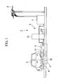
- Fig. 1 is a side view showing a schematic general configuration of a charging apparatus for an electric vehicle according to the present invention.
- the charging apparatus 1 is configured so that an electric vehicle 2 is parked on a dedicated parking lot, and a battery for driving a motor mounted on the electric vehicle 2 is charged in a non-contact manner.
- the charging apparatus 1 includes a power transmission system 3 provided on the ground, and a power receiving system 4 provided on a lower surface of a vehicle body of the electric vehicle 2.
- a method of feeding electric power in a non-contact manner an electric power conversion method using microwaves is applied herein.
- the power transmission system 3 includes a power supply unit 7 that takes in electric power from an external electric power line 6 (commercial power supply), and converts the electric power into power supply suitable for conversion into microwaves, a microwave conversion unit 8 that converts the electric power fed from the power supply unit 7 into microwaves of, for example, 2.45 GHz, a power transmission unit 10 provided on a substantially middle portion of a parking space of the electric vehicle 2, a power transmission conductor 11 that transmits the microwaves converted by the microwave conversion unit 8 to the power transmission unit 10, and water-cooling/hot-water supply equipment 12. As shown in Fig.
- the microwave conversion unit 8 includes a plurality of transformers 14, a rectifier 15, and a magnetron 16 in a conversion unit casing 8a, and further includes an interface 17 to the power supply unit 7, an interface 18 to the water-cooling/hot-water supply equipment 12, a control unit 20, and a communication unit 21.
- Electric power is fed from the power supply unit 7 via the interface 17 to the magnetron 16, and converted into microwaves by the magnetron 16. Since the fed electric power is partially converted into heat to cause the magnetron 16 to generate heat, the water-cooling/hot-water supply equipment 12 supplies cooling water via the interface 18 to the magnetron 16 to cool and increase the life of the magnetron 16. The cooling water heated by cooling the magnetron 16 is returned to the water-cooling/hot-water supply equipment 12, fed by a pump to hot-water supply equipment inside a house or the like and used as hot water. Thus, electric energy is recovered without waste.
- the power transmission unit 10 has, for example, a rectangular shape on plan view, and is provided horizontally on an upper portion of a power transmission unit casing 10a.
- a shielding member 23 in the form of a peripheral wall, for example, formed of a brush is provided to surround the power transmission unit 10.
- the shielding member 23 can be moved up and down by an up/down movement mechanism 24.
- a conduction sensor 26, a temperature sensor 27, a position sensor 28, or the like are added to the power transmission unit 10. Meanwhile, a power transmission conductor 11 is housed in a power transmission casing 11a to connect the magnetron 16 in the microwave conversion unit 8 and the power transmission unit 10.
- the power receiving system 4 provided on the lower surface of the vehicle body of the electric vehicle 2 includes a radiator 31 formed into a plate shape having a large area and secured to the lower surface of the vehicle body, and the power receiving unit 32 provided on a lower surface of a middle portion of the radiator 31.
- the radiator 31 includes many radiator fins 31a integrally formed of a material having high thermal conductivity such as aluminum and protruding downward.
- An unshown cooling cavity is formed in the radiator 31, and a cooling fan 33 is provided at one end of the radiator 31. Heat of the power receiving unit 32 generated during charging is transferred to the radiator 31, the cooling fan 33 supplies outside air to the cooling cavity in the radiator 31 to cool the heat of the power receiving unit 32 transferred to the radiator 31.
- the radiator 31 includes a control unit 35 and a temperature sensor 36, and further an interface 37 for connecting the power receiving unit 32 or the sensors to the vehicle body.
- the power receiving unit 32 has a rectangular shape on plan view, and is slightly smaller than the power transmission unit 10. For example, if the power transmission unit 10 has a length of 40 cm and a width of 30 cm, the power receiving unit 32 is set to have a length of about 30 cm and a width of about 20 cm. The power transmission unit 10 and the power receiving unit 32 may be smaller without any effect on power transmission and receiving performance.
- the power transmission unit 10 and the power receiving unit 32 may have a shape other than the rectangular shape, such as a circular shape or an oval shape.
- the electric vehicle 2 is parked so that the power receiving unit 32 on the lower surface of the vehicle body is aligned with the power transmission unit 10 provided on a substantially middle portion of a parking lot.
- the control unit 35 automatically checks a remaining battery level of the on-vehicle battery, and if the level is not full, charging is started.
- the position sensor 28 previously checks that the power receiving unit 32 is aligned with the power transmission unit 10 within a set range, and if misalignment is significant, charging is not started.
- the shielding member 23 surrounding the power transmission unit 10 is moved up to shield the power transmission unit 10 and the power receiving unit 32 from outside so as to prevent an influence of the microwaves from extending peripherally, and prevent foreign matter or insects from entering between the power transmission unit 10 and the power receiving unit 32.
- the microwaves converted from the electric power energy by the microwave conversion unit 8 are transmitted via the power transmission conductor 11 to the power transmission unit 10.
- the power transmission unit 10 aerially feeds electric power to the power receiving unit 32, and the power receiving unit 32 receives the electric power to charge the on-vehicle battery in a non-contact manner.
- the shielding member 23 is automatically moved down to about a height of the power transmission unit 10.
- charging can be performed without problem even if the power transmission unit 10 is slightly misaligned with the power receiving unit 32, and positional accuracy of parking of the electric vehicle 2 is less necessary.
- shielding means is provided for shielding the operation surface (lower surface) 32a of the power receiving unit 32 from outside without hindering power transmission and receiving action.
- Fig. 3 is a side view showing a first embodiment of a charging apparatus including shielding means in a power receiving unit 32.
- a rolling screen 41 that covers an operation surface of the power receiving unit 32 is provided as shielding means.
- the rolling screen 41 is formed of a strong film material such as an aramid material, for example, Kevlar (registered trademark of Du Pont: proper name is poly-paraphenylene terephthalamide).
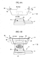
- the rolling screen 41 is configured to be opened/closed between a cover position 41a to cover the operation surface 32a of the power receiving unit 32, and an open position 41b to expose the power receiving unit 32 to an outside as shown in Fig. 4B .
- rollers 42, 43 extending in a width direction of the electric vehicle 2 are journaled at a front and a rear of a radiator 31 as a base of a power receiving system 4 to constitute a rolling-up mechanism 44, and the rolling screen 41 is stretched between the rollers 42, 43.
- the roller 42 located at a front in a vehicle traveling direction is always urged in a rotational direction F to roll up the rolling screen 41 toward the open position 41b.
- the roller 43 located at a rear in the vehicle traveling direction is rotated in a rotational direction R by a force of an unshown drive motor or the like to allow the rolling screen 41 rolled up on the roller 42 to be drawn to the cover position 41a against a biasing force of the roller 42.
- Fig. 4A when the rolling screen 41 is drawn to the cover position 41a, the rolling screen 41 is horizontally stretched in a position several millimeters to several centimeters below the power receiving unit 32 (operation surface 32a) to cover the power receiving unit 32.
- an end of the rolling screen 41 and the roller 43 are coupled by a pair of left and right drawing wires 46.
- the roller 42 is rotated in the rotational direction F to completely roll up the rolling screen 41, only the two drawing wires 46 are stretched between the roller 42 and the roller 43, and the power receiving unit 32 is exposed between the drawing wires 46.
- a space between the two drawing wires 46 (that is, a width of the rolling screen 41) is sufficiently larger than a width of the shielding member 23 of the power transmission unit 10 so that the drawing wires 46 do not interfere with the power transmission unit 10 and the power receiving unit 32 during charging.
- the rolling screen 41 is kept drawn to the cover position 41a by the control device 35 during traveling and non-charging of the electric vehicle 2, and rolled up to the open position 41b immediately before the electric vehicle 2 is parked in a predetermined position and charging is started.
- Such a rolling screen 41 is provided, and thus with an extremely simple and reliable configuration, the power receiving unit 32 can be shielded from outside to effectively prevent the operation surface 32a of the power receiving unit 32 from being contaminated by adhesion of mud, dust, or the like during traveling of the electric vehicle 2.
- the rolling screen 41 includes the rolling-up mechanism 44 to openably/closably cover the power receiving unit 32, and completely expose the power receiving unit 32 to the outside in the open position 41b.
- the rolling screen 41 can be closed to the cover position 41a to prevent contamination of the power receiving unit 32 during traveling of the electric vehicle 2, and the rolling screen 41 can be opened to the open position 41b to perform charging during charging.
- the rolling screen 41 is not interposed between the power transmission unit 10 on the ground and the power receiving unit 32 on the vehicle body during charging, thereby preventing a charging error and allowing reliable charging.
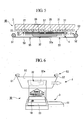
- Figs. 5 and 6 are side views showing a second embodiment of a charging apparatus including shielding means.
- a basic configuration of the charging apparatus 1B is the same as that of the charging apparatus 1A of the first embodiment except for the shielding means, and thus the same components are denoted by the same reference numerals and descriptions thereof will be omitted.
- a rolling screen 50 is provided as shielding means for covering an operation surface 32a of a power receiving unit 32.
- the rolling screen 50 is made of a material that does not hinder power transmission and receiving action between a power transmission unit 10 and the power receiving unit 32.
- a material through which microwaves can pass is preferable, and, for example, an aramid material similar to the material of the rolling screen 41 in the first embodiment is preferable.
- the rolling screen 50 is configured to always cover the power receiving unit 32.
- rollers 51, 52 are journaled at a front and a rear of a radiator 31 as a base of a power receiving system 4 to constitute a rolling-up mechanism 53, and the rolling screen 50 is stretched between the rollers 51, 52. Only a range of the rolling screen 50 covering the power receiving unit 32 is changed by the rolling-up mechanism 53, and the power receiving unit 32 is not exposed as in the first embodiment.
- the rolling screen 50 is always fed in one direction at predetermined time intervals.
- the rolling screen 50 is made of a material through which microwaves transmitted from the power transmission unit 10 to the power receiving unit 32 can pass, and thus charging can be performed with the rolling screen 50 covering the power receiving unit 32.
- the rolling screen 50 can always cover the power receiving unit 32, thereby reliably preventing contamination of the power receiving unit 32 and allowing stable charging.
- a soiled surface can be rolled up by the rolling-up mechanism 53 to always place a clean surface between the power transmission unit 10 and the power receiving unit 32, thereby avoiding an adverse effect due to overheating or the like of dirt adhering to the rolling screen 50.
- a pair of front and rear scrapers 55 are supported by unshown stay members so as to be located below the rolling screen 50 and in a front and a rear of the power receiving unit 32.
- the scraper 55 has, at an upper end, an edge portion that always slightly abuts against a lower surface of the rolling screen 50, and functions as sweeping means for sweeping off dirt such as mud adhering to the lower surface of the rolling screen 50 when the rolling screen 50 is rolled up by the rolling-up mechanism 53.
- Such sweeping means is provided to always keep a clean surface of the rolling screen 50.
- dirt adhering to the rolling screen 50 is prevented from being interposed between the power transmission unit 10 and the power receiving unit 32 to cause an adverse effect, thereby allowing stable charging.
- Figs. 7 and 8 are side views showing a third embodiment of a charging apparatus including shielding means.
- the charging apparatus 1C is a modification of the charging apparatus 1B of the second embodiment.
- the charging apparatus 1C is similar to the charging apparatus 1B in that rollers 57, 58 are journaled at a front and a rear of a radiator 31 to constitute a rolling-up mechanism 59, while the radiator 31 and a power receiving unit 32 are provided on an inner periphery of an annular rolling screen 60 provided to surround the rollers 57, 58, and the annular rolling screen 60 surrounds the entire power receiving system 4.
- the rolling screen 60 is made of a material through which microwaves can pass as in the charging apparatus 1B of the second embodiment.
- a pair of scrapers 55 are provided as sweeping means on a lower surface of the rolling screen 60 as in the second embodiment. As shown in Fig. 8 , the rolling screen 60 is always fed in one direction at predetermined time intervals, and every time the rolling screen 60 is fed, the scraper 55 sweeps off dirt adhering to the lower surface of the rolling screen 60.
- the power receiving unit 32 (operation surface 32a), and also the entire power receiving system 4 are surrounded by the rolling screen 60, thereby effectively preventing contamination of components of the power receiving system 4. Reducing a length of the rolling screen 60 and limiting a rotational direction of the rollers 57, 58 in one direction to simplify a structure of the rolling-up mechanism 59, thereby preventing failure or the like and increasing reliability.
- Fig. 9 is a perspective view showing a fourth embodiment of a charging apparatus including shielding means.
- a shutter mechanism 63 formed of a rigid body of such as metal or resin is used as shielding means rather than the rolling screen to openably/closable cover the power receiving unit 32.
- the entire power receiving system 4 is housed in a dustproof box 64, for example, made of resin, a large opening 64a is formed in a lower surface of the dustproof box 64 to match a position of the power receiving unit 32 so that the opening 64a is opened/closed by the shutter mechanism 63.
- the opening 64a is desirably larger than an outer size of shielding member 23 so that a tip of the shielding member 23 enters the opening 64a during charging.
- the shutter mechanism 63 In the charging apparatus 1D, during traveling and non-charging of the electric vehicle 2, the shutter mechanism 63 is closed to protect the entire power receiving system 4 from contamination, the shutter mechanism 63 is opened to expose the power receiving unit 32 to the outside only during charging, and non-contact charging is performed between the power receiving unit 32 and the power transmission unit 10. According to this configuration, the power receiving unit 32 is shielded from outside by the shutter mechanism 63 and prevented from being contaminated, thereby allowing stable charging.
- the shutter mechanism 63 can be robustly configured, thereby increasing reliability of the charging apparatus 1D.
- the radiator 31 (see Fig. 2 ) that radiates heat generated by the power receiving unit 32 during charging is also housed in the dustproof box 64, and thus a cooling fan for taking outside air as cooling air into the dustproof box 64 is preferably provided so that the radiator 31 can easily perform heat exchange with the outside air.
- the cooling fan sucks outside air
- a filter member removes dust from the outside air
- the air is then taken into the dustproof box 64 as cooling air
- the cooling air heated by heat from the radiator 31 is discharged from the opening 64a, thereby preventing foreign matter such as dust from entering through the opening 64a into the dustproof box 64.
- shielding means similar to those in the first to fourth embodiments may be added to the power transmission unit 10 on the ground. This can prevent fallen leaves or insects from being accumulated on the operation surface (upper surface) of the transmission unit 10 and allow stable charging.
Landscapes
- Engineering & Computer Science (AREA)
- Power Engineering (AREA)
- Computer Networks & Wireless Communication (AREA)
- Transportation (AREA)
- Mechanical Engineering (AREA)
- Electrochemistry (AREA)
- Chemical & Material Sciences (AREA)
- Chemical Kinetics & Catalysis (AREA)
- Manufacturing & Machinery (AREA)
- General Chemical & Material Sciences (AREA)
- Physics & Mathematics (AREA)
- Electromagnetism (AREA)
- Electric Propulsion And Braking For Vehicles (AREA)
- Charge And Discharge Circuits For Batteries Or The Like (AREA)
- Secondary Cells (AREA)
- Current-Collector Devices For Electrically Propelled Vehicles (AREA)
- Body Structure For Vehicles (AREA)
- Arrangement Or Mounting Of Propulsion Units For Vehicles (AREA)
Abstract
Provided is a charging apparatus for an electric vehicle which, through a simple and highly reliable structure, prevents fouling of a power receiving section of an electric vehicle and enables charging to be performed in a stable manner. In this charging apparatus (1A) for an electric vehicle, an electric vehicle is parked over a power transmitting section installed on the ground side so that the power receiving section (32) provided on the lower surface of the vehicle body of the electric vehicle aligns with the position of the power transmitting section, and electric power energy transmitted through the air from the power transmitting section is received by the power receiving section (32) so that a battery mounted on the electric vehicle side is charged wirelessly. This charging apparatus is provided with a protective means for protecting an operation surface (32a) of the power receiving section (32) eternally without reducing the effect of power transmission and power reception. For this protective means, a roll screen (41) is suitable.
Description
- The present invention relates to a charging apparatus for an electric vehicle in which the electric vehicle is stopped on a power transmission unit provided on the ground, and a battery mounted on the electric vehicle is charged in a non-contact manner.
- Recently, for conservation of global environment, electric vehicles such as hybrid vehicles that travel by driving an electric motor using electric power of an on-vehicle battery in addition to power of an internal combustion engine, and electric automobiles that travel using a drive force of only an electric motor have rapidly become widespread. A non-contact charging apparatus for an electric vehicle as disclosed in
PTLs - Such a charging apparatus includes a power transmission unit provided on the ground such as a floor of a parking lot, and a power receiving unit provided on a lower surface of a vehicle body of an electric vehicle. In charging an on-vehicle battery, the vehicle body is parked so that the power receiving unit on the vehicle body is located immediately above the power transmission unit on the ground, and electric power is fed from the power transmission unit to the power receiving unit for charging by electromagnetic induction without contact between the power transmission unit and the power receiving unit. A non-contact method for electric power feeding may include microwaves or magnetic resonance besides electromagnetic induction.
-
- {PTL 1}
Japanese Unexamined Patent Application, Publication No.2008-253131 - {PTL 2}
Japanese Unexamined Patent Application, Publication No.2009-106136 - In this way, in the charging apparatus including the power receiving unit provided on the lower surface of the vehicle body of the electric vehicle, mud, dust, or the like tends to adhere to and contaminate the power receiving unit during traveling of the vehicle. If non-contact charging is performed with the power receiving unit being contaminated, a charging error is highly likely to occur. Also, for example, in non-contact charging using microwaves, adhering dirt may be overheated to cause smoking, ignition, anchoring, or the like depending on components of the dirt.
- In order to remove dirt adhering to the power receiving unit before start of charging, for example, a water nozzle may be provided on the power transmission unit so as to jet water or hot water toward the power receiving unit to wash the power receiving unit, or a cleaning brush that can protrude upward may be provided on the power transmission unit to brush off dirt on the power receiving unit from below. However, providing the water nozzle or the cleaning brush on the power transmission unit increases a size of power transmission equipment, which is unpreferable in terms of cost or maintenance.
- The present invention is achieved in view of the above described circumstances, and provides a charging apparatus for an electric vehicle that has a simple and reliable structure, and thus prevents contamination of a power receiving unit provided on an electric vehicle, or a power transmission unit provided on the ground, and allows stable charging.
- To achieve the above described object, the present invention adopts means described below.
A first aspect of the present invention provides a charging apparatus for an electric vehicle in which the electric vehicle is parked on a power transmission unit provided on the ground, a power receiving unit provided on a lower surface of a vehicle body of the electric vehicle is aligned with the power transmission unit, and the power receiving unit receives electric power energy aerially fed from the power transmission unit to charge a battery mounted on the electric vehicle in a non-contact manner, wherein the charging apparatus comprises shielding means for shielding an operation surface of at least one of the power receiving unit and the power transmission unit from outside without hindering power transmission and receiving action. - According to the above configuration, the shielding means shields the operation surface of the power receiving unit or the power transmission unit from outside to prevent contamination of the operation surface. For example, if the shielding means is added to the power receiving unit provided on the lower surface of the vehicle body of the electric vehicle, the power receiving unit is prevented from being contaminated by adhesion of mud, dust, or the like during traveling of the electric vehicle. Also, if the shielding means is added to the power transmission unit provided on a floor of a parking lot, fallen leaves or insects are prevented from being accumulated on the power transmission unit. This allows stable charging.
- A second aspect of the present invention provides the charging apparatus for an electric vehicle in the first aspect, wherein the shielding means is a rolling screen provided to cover the operation surface. According to this configuration, an extremely simple and reliable configuration can prevent contamination of the power receiving unit provided on the electric vehicle or the power transmission unit provided on the ground.
- In the second aspect, the rolling screen may include a rolling-up mechanism so as to openably/closably cover the operation surface, and expose the operation surface to an outside when opened.
- In the above described configuration, for example, when the power receiving unit provided on the lower surface of the vehicle body of the electric vehicle is covered with the rolling screen, the rolling screen can be closed during traveling to prevent contamination of the power receiving unit, and the rolling screen can be opened for charging. During charging, the rolling screen is not interposed between the power transmission unit on the ground and the power receiving unit on the vehicle body, thereby preventing a charging error and allowing reliable charging.
- In the second aspect, the rolling screen may be made of a material that does not hinder power transmission and receiving action, and always cover the operation surface, and the rolling-up mechanism may change a covering range of the operation surface.
- According to the above described configuration, even if the rolling screen is interposed between the power transmission unit on the ground and the power receiving unit on the vehicle body, the rolling screen does not hinder the power transmission and receiving action. Thus, the rolling screen can always cover the power transmission unit or the power receiving unit, thereby reliably preventing contamination of the power transmission unit and the power receiving unit and allowing stable charging.
Further, even if the rolling screen is soiled, a soiled surface can be rolled up by the rolling-up mechanism to always place a clean surface between the power transmission unit and the power receiving unit, thereby avoiding an adverse effect due to overheating or the like of dirt adhering to the rolling screen. - The charging apparatus for an electric vehicle according to any one of the above described aspects may include sweeping means for sweeping off dirt adhering to the surface of the rolling screen with opening/closing and rolling-up operations of the rolling screen.
- According to the above described configuration, every time the opening/closing and rolling-up operations of the rolling screen are performed, the sweeping means sweeps off the dirt adhering to the surface of the rolling screen to always keep a clean surface of the rolling screen. Thus, particularly for the charging apparatus in which the rolling screen always cover the power transmission unit or the power receiving unit, dirt adhering to the rolling screen is prevented from being interposed between the power transmission unit and the power receiving unit to cause an adverse effect, thereby allowing stable charging.
- In the first aspect, the shielding means may be a shutter mechanism that is formed of a rigid body and openably/closably covers the operation surface. According to this configuration, the operation surface of the power receiving unit or the power transmission unit is shielded from outside by the shutter mechanism to prevent contamination of the operation surface, thereby allowing stable charging. The shutter mechanism can be robustly configured, thereby increasing reliability.
- As described above, according to the charging apparatus for an electric vehicle of the present invention, a charging apparatus for an electric vehicle can be provided that has a simple and reliable structure and thus can prevent contamination of a power receiving unit provided on the electric vehicle.
-
- {
Fig. 1 }
Fig. 1 is a side view showing a schematic general configuration of a charging apparatus for an electric vehicle according to the present invention. - {
Fig. 2 }
Fig. 2 is an enlarged side view of the charging apparatus shown inFig. 1 . - {
Fig. 3 }
Fig. 3 is a side view of a charging apparatus (power receiving unit) according to a first embodiment of the present invention. - {
Fig. 4A }
Fig. 4A shows a non-charging state where the power receiving unit is covered with a rolling screen. - {
Fig. 4B }
Fig. 4B shows a charging state where the power receiving unit is exposed to an outside. - {
Fig. 5 }
Fig. 5 is a side view of a charging apparatus (power receiving unit) according to a second embodiment of the present invention. - {
Fig. 6 }
Fig. 6 shows an operation of a rolling screen shown inFig. 5 . - {
Fig. 7 }
Fig. 7 is a side view of a charging apparatus (power receiving unit) according to a third embodiment of the present invention. - {
Fig. 8 }
Fig. 8 shows an operation of a rolling screen shown inFig. 7 . - {
Fig. 9 }
Fig. 9 is a perspective view of a charging apparatus (power receiving unit) according to a fourth embodiment of the present invention. - Now, multiple embodiments of a charging apparatus for an electric vehicle according to the present invention will be described with reference to the drawings.
-
Fig. 1 is a side view showing a schematic general configuration of a charging apparatus for an electric vehicle according to the present invention. The chargingapparatus 1 is configured so that anelectric vehicle 2 is parked on a dedicated parking lot, and a battery for driving a motor mounted on theelectric vehicle 2 is charged in a non-contact manner. The chargingapparatus 1 includes apower transmission system 3 provided on the ground, and apower receiving system 4 provided on a lower surface of a vehicle body of theelectric vehicle 2. As an example of a method of feeding electric power in a non-contact manner, an electric power conversion method using microwaves is applied herein. - The
power transmission system 3 includes apower supply unit 7 that takes in electric power from an external electric power line 6 (commercial power supply), and converts the electric power into power supply suitable for conversion into microwaves, amicrowave conversion unit 8 that converts the electric power fed from thepower supply unit 7 into microwaves of, for example, 2.45 GHz, apower transmission unit 10 provided on a substantially middle portion of a parking space of theelectric vehicle 2, apower transmission conductor 11 that transmits the microwaves converted by themicrowave conversion unit 8 to thepower transmission unit 10, and water-cooling/hot-water supply equipment 12. As shown inFig. 2 , themicrowave conversion unit 8 includes a plurality oftransformers 14, arectifier 15, and amagnetron 16 in aconversion unit casing 8a, and further includes aninterface 17 to thepower supply unit 7, aninterface 18 to the water-cooling/hot-water supply equipment 12, acontrol unit 20, and acommunication unit 21. - Electric power is fed from the
power supply unit 7 via theinterface 17 to themagnetron 16, and converted into microwaves by themagnetron 16. Since the fed electric power is partially converted into heat to cause themagnetron 16 to generate heat, the water-cooling/hot-water supply equipment 12 supplies cooling water via theinterface 18 to themagnetron 16 to cool and increase the life of themagnetron 16. The cooling water heated by cooling themagnetron 16 is returned to the water-cooling/hot-water supply equipment 12, fed by a pump to hot-water supply equipment inside a house or the like and used as hot water. Thus, electric energy is recovered without waste. - The
power transmission unit 10 has, for example, a rectangular shape on plan view, and is provided horizontally on an upper portion of a powertransmission unit casing 10a. A shieldingmember 23 in the form of a peripheral wall, for example, formed of a brush is provided to surround thepower transmission unit 10. The shieldingmember 23 can be moved up and down by an up/downmovement mechanism 24. Aconduction sensor 26, a temperature sensor 27, aposition sensor 28, or the like are added to thepower transmission unit 10. Meanwhile, apower transmission conductor 11 is housed in apower transmission casing 11a to connect themagnetron 16 in themicrowave conversion unit 8 and thepower transmission unit 10. - On the other hand, the
power receiving system 4 provided on the lower surface of the vehicle body of theelectric vehicle 2 includes aradiator 31 formed into a plate shape having a large area and secured to the lower surface of the vehicle body, and thepower receiving unit 32 provided on a lower surface of a middle portion of theradiator 31. Theradiator 31 includesmany radiator fins 31a integrally formed of a material having high thermal conductivity such as aluminum and protruding downward. An unshown cooling cavity is formed in theradiator 31, and a coolingfan 33 is provided at one end of theradiator 31. Heat of thepower receiving unit 32 generated during charging is transferred to theradiator 31, the coolingfan 33 supplies outside air to the cooling cavity in theradiator 31 to cool the heat of thepower receiving unit 32 transferred to theradiator 31. Theradiator 31 includes acontrol unit 35 and atemperature sensor 36, and further aninterface 37 for connecting thepower receiving unit 32 or the sensors to the vehicle body. - The
power receiving unit 32 has a rectangular shape on plan view, and is slightly smaller than thepower transmission unit 10. For example, if thepower transmission unit 10 has a length of 40 cm and a width of 30 cm, thepower receiving unit 32 is set to have a length of about 30 cm and a width of about 20 cm. Thepower transmission unit 10 and thepower receiving unit 32 may be smaller without any effect on power transmission and receiving performance. Thepower transmission unit 10 and thepower receiving unit 32 may have a shape other than the rectangular shape, such as a circular shape or an oval shape. - The
electric vehicle 2 is parked so that thepower receiving unit 32 on the lower surface of the vehicle body is aligned with thepower transmission unit 10 provided on a substantially middle portion of a parking lot. When, for example, an ignition key of theelectric vehicle 2 is removed, thecontrol unit 35 automatically checks a remaining battery level of the on-vehicle battery, and if the level is not full, charging is started. At this time, theposition sensor 28 previously checks that thepower receiving unit 32 is aligned with thepower transmission unit 10 within a set range, and if misalignment is significant, charging is not started. - When it is confirmed that the
power receiving unit 32 is aligned with thepower transmission unit 10 within a set range, the shieldingmember 23 surrounding thepower transmission unit 10 is moved up to shield thepower transmission unit 10 and thepower receiving unit 32 from outside so as to prevent an influence of the microwaves from extending peripherally, and prevent foreign matter or insects from entering between thepower transmission unit 10 and thepower receiving unit 32. When the charging apparatus is thus ready for charging, the microwaves converted from the electric power energy by themicrowave conversion unit 8 are transmitted via thepower transmission conductor 11 to thepower transmission unit 10. Further, thepower transmission unit 10 aerially feeds electric power to thepower receiving unit 32, and thepower receiving unit 32 receives the electric power to charge the on-vehicle battery in a non-contact manner. When the charging is completed, the shieldingmember 23 is automatically moved down to about a height of thepower transmission unit 10. In such a non-contact charging method using microwaves, charging can be performed without problem even if thepower transmission unit 10 is slightly misaligned with thepower receiving unit 32, and positional accuracy of parking of theelectric vehicle 2 is less necessary. - Meanwhile, during traveling of the
electric vehicle 2, mud, dust, or the like tends to adhere to thepower receiving unit 32 in thepower receiving system 4 provided on the lower surface of the vehicle body. In order to prevent such contamination of thepower receiving unit 32, shielding means is provided for shielding the operation surface (lower surface) 32a of thepower receiving unit 32 from outside without hindering power transmission and receiving action. First to fourth embodiments of the shielding means will be individually described below. -
Fig. 3 is a side view showing a first embodiment of a charging apparatus including shielding means in apower receiving unit 32. In thecharging apparatus 1A, a rollingscreen 41 that covers an operation surface of thepower receiving unit 32 is provided as shielding means. The rollingscreen 41 is formed of a strong film material such as an aramid material, for example, Kevlar (registered trademark of Du Pont: proper name is poly-paraphenylene terephthalamide). As shown inFigs. 3 and4A , the rollingscreen 41 is configured to be opened/closed between acover position 41a to cover theoperation surface 32a of thepower receiving unit 32, and anopen position 41b to expose thepower receiving unit 32 to an outside as shown inFig. 4B . Specifically, for example,rollers electric vehicle 2 are journaled at a front and a rear of aradiator 31 as a base of apower receiving system 4 to constitute a rolling-upmechanism 44, and the rollingscreen 41 is stretched between therollers - For example, the
roller 42 located at a front in a vehicle traveling direction is always urged in a rotational direction F to roll up the rollingscreen 41 toward theopen position 41b. Theroller 43 located at a rear in the vehicle traveling direction is rotated in a rotational direction R by a force of an unshown drive motor or the like to allow therolling screen 41 rolled up on theroller 42 to be drawn to thecover position 41a against a biasing force of theroller 42. As shown inFig. 4A , when the rollingscreen 41 is drawn to thecover position 41a, the rollingscreen 41 is horizontally stretched in a position several millimeters to several centimeters below the power receiving unit 32 (operation surface 32a) to cover thepower receiving unit 32. - As shown in
Fig. 4B , for example, an end of the rollingscreen 41 and theroller 43 are coupled by a pair of left andright drawing wires 46. When theroller 42 is rotated in the rotational direction F to completely roll up the rollingscreen 41, only the twodrawing wires 46 are stretched between theroller 42 and theroller 43, and thepower receiving unit 32 is exposed between the drawingwires 46. A space between the two drawing wires 46 (that is, a width of the rolling screen 41) is sufficiently larger than a width of the shieldingmember 23 of thepower transmission unit 10 so that thedrawing wires 46 do not interfere with thepower transmission unit 10 and thepower receiving unit 32 during charging. - The rolling
screen 41 is kept drawn to thecover position 41a by thecontrol device 35 during traveling and non-charging of theelectric vehicle 2, and rolled up to theopen position 41b immediately before theelectric vehicle 2 is parked in a predetermined position and charging is started. - Such a rolling
screen 41 is provided, and thus with an extremely simple and reliable configuration, thepower receiving unit 32 can be shielded from outside to effectively prevent theoperation surface 32a of thepower receiving unit 32 from being contaminated by adhesion of mud, dust, or the like during traveling of theelectric vehicle 2. The rollingscreen 41 includes the rolling-upmechanism 44 to openably/closably cover thepower receiving unit 32, and completely expose thepower receiving unit 32 to the outside in theopen position 41b. Thus, the rollingscreen 41 can be closed to thecover position 41a to prevent contamination of thepower receiving unit 32 during traveling of theelectric vehicle 2, and the rollingscreen 41 can be opened to theopen position 41b to perform charging during charging. The rollingscreen 41 is not interposed between thepower transmission unit 10 on the ground and thepower receiving unit 32 on the vehicle body during charging, thereby preventing a charging error and allowing reliable charging. -
Figs. 5 and 6 are side views showing a second embodiment of a charging apparatus including shielding means. A basic configuration of the chargingapparatus 1B is the same as that of thecharging apparatus 1A of the first embodiment except for the shielding means, and thus the same components are denoted by the same reference numerals and descriptions thereof will be omitted. Also in thecharging apparatus 1B, a rollingscreen 50 is provided as shielding means for covering anoperation surface 32a of apower receiving unit 32. The rollingscreen 50 is made of a material that does not hinder power transmission and receiving action between apower transmission unit 10 and thepower receiving unit 32. A material through which microwaves can pass is preferable, and, for example, an aramid material similar to the material of the rollingscreen 41 in the first embodiment is preferable. - The rolling
screen 50 is configured to always cover thepower receiving unit 32. Specifically, as in the first embodiment,rollers radiator 31 as a base of apower receiving system 4 to constitute a rolling-upmechanism 53, and the rollingscreen 50 is stretched between therollers screen 50 covering thepower receiving unit 32 is changed by the rolling-upmechanism 53, and thepower receiving unit 32 is not exposed as in the first embodiment. As shown inFig. 6 , the rollingscreen 50 is always fed in one direction at predetermined time intervals. - The rolling
screen 50 is made of a material through which microwaves transmitted from thepower transmission unit 10 to thepower receiving unit 32 can pass, and thus charging can be performed with the rollingscreen 50 covering thepower receiving unit 32. Thus, the rollingscreen 50 can always cover thepower receiving unit 32, thereby reliably preventing contamination of thepower receiving unit 32 and allowing stable charging. Also, even if the rollingscreen 50 is soiled, a soiled surface can be rolled up by the rolling-upmechanism 53 to always place a clean surface between thepower transmission unit 10 and thepower receiving unit 32, thereby avoiding an adverse effect due to overheating or the like of dirt adhering to the rollingscreen 50. - Further, a pair of front and
rear scrapers 55 are supported by unshown stay members so as to be located below the rollingscreen 50 and in a front and a rear of thepower receiving unit 32. Thescraper 55 has, at an upper end, an edge portion that always slightly abuts against a lower surface of the rollingscreen 50, and functions as sweeping means for sweeping off dirt such as mud adhering to the lower surface of the rollingscreen 50 when the rollingscreen 50 is rolled up by the rolling-upmechanism 53. - Such sweeping means is provided to always keep a clean surface of the rolling
screen 50. Thus, for a configuration like thecharging apparatus 1B in which therolling screen 50 always cover thepower receiving unit 32, dirt adhering to the rollingscreen 50 is prevented from being interposed between thepower transmission unit 10 and thepower receiving unit 32 to cause an adverse effect, thereby allowing stable charging. -
Figs. 7 and 8 are side views showing a third embodiment of a charging apparatus including shielding means. The chargingapparatus 1C is a modification of the chargingapparatus 1B of the second embodiment. Specifically, the chargingapparatus 1C is similar to thecharging apparatus 1B in thatrollers radiator 31 to constitute a rolling-upmechanism 59, while theradiator 31 and apower receiving unit 32 are provided on an inner periphery of anannular rolling screen 60 provided to surround therollers annular rolling screen 60 surrounds the entirepower receiving system 4. - The rolling
screen 60 is made of a material through which microwaves can pass as in thecharging apparatus 1B of the second embodiment. A pair ofscrapers 55 are provided as sweeping means on a lower surface of the rollingscreen 60 as in the second embodiment. As shown inFig. 8 , the rollingscreen 60 is always fed in one direction at predetermined time intervals, and every time the rollingscreen 60 is fed, thescraper 55 sweeps off dirt adhering to the lower surface of the rollingscreen 60. - According to the above described configuration, the power receiving unit 32 (
operation surface 32a), and also the entirepower receiving system 4 are surrounded by the rollingscreen 60, thereby effectively preventing contamination of components of thepower receiving system 4. Reducing a length of the rollingscreen 60 and limiting a rotational direction of therollers mechanism 59, thereby preventing failure or the like and increasing reliability. -
Fig. 9 is a perspective view showing a fourth embodiment of a charging apparatus including shielding means. In the chargingapparatus 1D, ashutter mechanism 63 formed of a rigid body of such as metal or resin is used as shielding means rather than the rolling screen to openably/closable cover thepower receiving unit 32. Specifically, the entirepower receiving system 4 is housed in adustproof box 64, for example, made of resin, alarge opening 64a is formed in a lower surface of thedustproof box 64 to match a position of thepower receiving unit 32 so that theopening 64a is opened/closed by theshutter mechanism 63. Theopening 64a is desirably larger than an outer size of shieldingmember 23 so that a tip of the shieldingmember 23 enters theopening 64a during charging. - In the charging
apparatus 1D, during traveling and non-charging of theelectric vehicle 2, theshutter mechanism 63 is closed to protect the entirepower receiving system 4 from contamination, theshutter mechanism 63 is opened to expose thepower receiving unit 32 to the outside only during charging, and non-contact charging is performed between thepower receiving unit 32 and thepower transmission unit 10. According to this configuration, thepower receiving unit 32 is shielded from outside by theshutter mechanism 63 and prevented from being contaminated, thereby allowing stable charging. Theshutter mechanism 63 can be robustly configured, thereby increasing reliability of the chargingapparatus 1D. - The radiator 31 (see
Fig. 2 ) that radiates heat generated by thepower receiving unit 32 during charging is also housed in thedustproof box 64, and thus a cooling fan for taking outside air as cooling air into thedustproof box 64 is preferably provided so that theradiator 31 can easily perform heat exchange with the outside air. In this case, the cooling fan sucks outside air, a filter member removes dust from the outside air, the air is then taken into thedustproof box 64 as cooling air, and the cooling air heated by heat from theradiator 31 is discharged from theopening 64a, thereby preventing foreign matter such as dust from entering through theopening 64a into thedustproof box 64. - It goes without saying that the technical range of the present invention is not limited to the aspects of the embodiments, and for example, the aspects of the embodiments may be combined. Also, shielding means similar to those in the first to fourth embodiments may be added to the
power transmission unit 10 on the ground. This can prevent fallen leaves or insects from being accumulated on the operation surface (upper surface) of thetransmission unit 10 and allow stable charging. -
- 1, 1A, 1B, 1C, 1D
- charging apparatus
- 2
- electric vehicle
- 3
- power transmission system
- 4
- power receiving system
- 8
- microwave conversion unit
- 10
- power transmission unit
- 23
- shielding member
- 32
- power receiving unit
- 32a
- operation surface
- 41, 50, 60
- rolling screen (shielding means)
- 44, 53, 59
- rolling-up mechanism
- 63
- shutter mechanism (shielding means)
Claims (6)
- A charging apparatus for an electric vehicle in which the electric vehicle is parked on a power transmission unit provided on the ground, a power receiving unit provided on a lower surface of a vehicle body of the electric vehicle is aligned with the power transmission unit, and the power receiving unit receives electric power energy aerially fed from the power transmission unit to charge a battery mounted on the electric vehicle in a non-contact manner, the charging apparatus comprising:a shielding means for shielding an operation surface of at least one of the power receiving unit and the power transmission unit from outside without hindering power transmission and receiving action.
- The charging apparatus for an electric vehicle according to claim 1, wherein the shielding means is a rolling screen provided to cover the operation surface.
- The charging apparatus for an electric vehicle according to claim 2, wherein the rolling screen includes a rolling-up mechanism so as to openably/closably cover the operation surface, and expose the operation surface to an outside when opened.
- The charging apparatus for an electric vehicle according to claim 2, wherein the rolling screen is made of a material that does not hinder power transmission and receiving action, and always covers the operation surface, and the rolling-up mechanism changes a covering range of the operation surface.
- The charging apparatus for an electric vehicle according to any one of claims 2 to 4, further comprising a sweeping means for sweeping off dirt adhering to the surface of the rolling screen with opening/closing and rolling-up operations of the rolling screen.
- The charging apparatus for an electric vehicle according to claim 1, wherein the shielding means is a shutter mechanism that is formed of a rigid body and openably/closably covers the operation surface.
Applications Claiming Priority (2)
| Application Number | Priority Date | Filing Date | Title |
|---|---|---|---|
| JP2011006023A JP5843446B2 (en) | 2011-01-14 | 2011-01-14 | Electric vehicle charging device |
| PCT/JP2012/050404 WO2012096316A1 (en) | 2011-01-14 | 2012-01-11 | Charging apparatus for electric vehicle |
Publications (1)
| Publication Number | Publication Date |
|---|---|
| EP2664482A1 true EP2664482A1 (en) | 2013-11-20 |
Family
ID=46507208
Family Applications (1)
| Application Number | Title | Priority Date | Filing Date |
|---|---|---|---|
| EP12734264.0A Withdrawn EP2664482A1 (en) | 2011-01-14 | 2012-01-11 | Charging apparatus for electric vehicle |
Country Status (5)
| Country | Link |
|---|---|
| US (1) | US9566870B2 (en) |
| EP (1) | EP2664482A1 (en) |
| JP (1) | JP5843446B2 (en) |
| CN (1) | CN103140369B (en) |
| WO (1) | WO2012096316A1 (en) |
Families Citing this family (34)
| Publication number | Priority date | Publication date | Assignee | Title |
|---|---|---|---|---|
| JP6170055B2 (en) * | 2012-09-20 | 2017-07-26 | 富士機械製造株式会社 | Non-contact power feeding device |
| GB2510125B (en) * | 2013-01-24 | 2015-07-08 | Jaguar Land Rover Ltd | Vehicle charging method and apparatus |
| CN104956568B (en) * | 2013-02-08 | 2017-06-23 | 株式会社 Ihi | Heat transfer unit (HTU), electric supply installation and contactless power supply system |
| JP5857999B2 (en) * | 2013-04-26 | 2016-02-10 | トヨタ自動車株式会社 | Power receiving device, parking assist device, and power transmission system |
| JP6149499B2 (en) * | 2013-05-14 | 2017-06-21 | 株式会社Ihi | Contactless power supply system |
| FR3010253B1 (en) * | 2013-09-04 | 2017-06-16 | Schneider Electric Ind Sas | INDUCTION CHARGING DEVICE BY INDUCTION OF A BATTERY OF AN ELECTRIC VEHICLE, AND INDUCTION RECHARGING SYSTEM COMPRISING SUCH A DEVICE |
| EP3056380A4 (en) * | 2013-09-10 | 2017-04-19 | The Chugoku Electric Power Co., Inc. | Contactless power feeding system, and contactless power feeding method |
| EP3073601B1 (en) | 2013-11-18 | 2019-06-12 | IHI Corporation | Wireless power supply system |
| JP5910642B2 (en) * | 2014-01-22 | 2016-04-27 | トヨタ自動車株式会社 | Contactless charging system |
| GB201403548D0 (en) | 2014-02-28 | 2014-04-16 | Bombardier Transp Gmbh | Inductive power transfer pad comprising a stationary part and a moveable part |
| EP3151378B1 (en) * | 2014-05-19 | 2023-03-08 | IHI Corporation | Cooling device and wireless power supply system |
| JP6337653B2 (en) * | 2014-06-30 | 2018-06-06 | 株式会社Ihi | Foreign matter removal device, ground-side equipment of contactless power supply system, contactless power supply system |
| JP6292538B2 (en) * | 2014-09-08 | 2018-03-14 | 株式会社Ihi | Foreign matter removal device for non-contact power feeding device |
| CN106232248B (en) | 2014-06-30 | 2019-05-10 | 株式会社Ihi | Foreign matter removal device, ground side equipment of non-contact power supply system, non-contact power supply system |
| US10601251B2 (en) | 2014-08-12 | 2020-03-24 | Apple Inc. | System and method for power transfer |
| JP6176272B2 (en) * | 2015-02-27 | 2017-08-09 | トヨタ自動車株式会社 | Power transmission system |
| US10399449B2 (en) * | 2016-08-08 | 2019-09-03 | Hyundai Motor Company | Wireless charging control apparatus and method for optimal charging by adjusting the inclination of the electric vehicle being charged |
| EP3627654B1 (en) * | 2016-09-26 | 2021-07-07 | Volvo Car Corporation | A vehicle charging interface unit, a system for charging a vehicle and a vehicle |
| CN106486718A (en) * | 2016-12-06 | 2017-03-08 | 东南(福建)汽车工业有限公司 | A kind of batteries of electric automobile bag insulation and controller for heat sink |
| JP6551755B2 (en) * | 2017-02-09 | 2019-07-31 | パナソニックIpマネジメント株式会社 | Control method of power transmission device in wireless power transmission system, and power transmission device |
| WO2018146973A1 (en) * | 2017-02-09 | 2018-08-16 | パナソニックIpマネジメント株式会社 | Method for controlling power transmission device in wireless power transmission system, and power transmission device |
| DE102017115642B3 (en) | 2017-07-12 | 2018-07-19 | Dr. Ing. H.C. F. Porsche Aktiengesellschaft | Method and device for electrically charging electric vehicles |
| KR20190043917A (en) | 2017-10-19 | 2019-04-29 | 한국전력공사 | Multiple wireless charging system for electric vehicles |
| US11034254B2 (en) * | 2017-12-11 | 2021-06-15 | Zoox, Inc. | Underbody charging of vehicle batteries |
| US10682921B2 (en) | 2017-12-11 | 2020-06-16 | Zoox, Inc. | Underbody charging of vehicle batteries |
| DE102018112494B4 (en) * | 2018-05-24 | 2023-03-16 | Schunk Transit Systems Gmbh | Contact device and rapid charging system |
| CN118205412A (en) * | 2018-10-17 | 2024-06-18 | 合芯磁导科技(无锡)有限公司 | Telescopic safety guard rail for wireless charging transmitter of electric automobile |
| GB2580865A (en) * | 2018-10-23 | 2020-08-05 | Bombardier Primove Gmbh | Stationary part for an inductive power transfer pad |
| DE102018009010B4 (en) * | 2018-11-16 | 2024-04-25 | Easelink Gmbh | Underbody charging unit and vehicle with an underbody charging unit |
| EP3842280A1 (en) * | 2019-12-26 | 2021-06-30 | Aptiv Technologies Limited | Inlet connector with cooler |
| CN112217257A (en) * | 2020-10-21 | 2021-01-12 | 阳光电源股份有限公司 | a charging pile |
| CN112140933B (en) * | 2020-10-21 | 2022-05-24 | 阳光电源股份有限公司 | Charging pile |
| US12139030B1 (en) | 2021-08-11 | 2024-11-12 | Zoox, Inc. | Lift mechanism for aligning charging elements to charge vehicle |
| FR3160133B1 (en) * | 2024-03-13 | 2026-02-06 | Stellantis Auto Sas | ELECTRIC OR HYBRID MOTOR VEHICLE WITH A FLEXIBLE CHARGING CAP |
Family Cites Families (9)
| Publication number | Priority date | Publication date | Assignee | Title |
|---|---|---|---|---|
| US5392835A (en) * | 1993-04-07 | 1995-02-28 | Irowi-Insektenschutz-Rollgitter Gmbh | Roll-type insect screen assembly |
| JPH07236204A (en) | 1994-02-22 | 1995-09-05 | Hitachi Ltd | Method and system for charging electric automobile |
| JPH10214737A (en) * | 1997-01-28 | 1998-08-11 | Sumitomo Wiring Syst Ltd | Magnetic coupler for charging electric automobile |
| JPH10304583A (en) | 1997-04-25 | 1998-11-13 | Sumitomo Wiring Syst Ltd | Electric vehicle charging connector |
| JP2001177916A (en) | 1999-12-10 | 2001-06-29 | Toyota Motor Corp | Energy-supplying apparatus |
| CN2440693Y (en) * | 2000-08-25 | 2001-08-01 | 中山市隆成日用制品有限公司 | Charge Controller for Children's Electric Vehicles |
| JP4865451B2 (en) | 2006-08-24 | 2012-02-01 | 三菱重工業株式会社 | Power receiving device, power transmitting device, and vehicle |
| JP4453741B2 (en) * | 2007-10-25 | 2010-04-21 | トヨタ自動車株式会社 | Electric vehicle and vehicle power supply device |
| JP4743244B2 (en) * | 2008-09-18 | 2011-08-10 | トヨタ自動車株式会社 | Non-contact power receiving device |
-
2011
- 2011-01-14 JP JP2011006023A patent/JP5843446B2/en not_active Expired - Fee Related
-
2012
- 2012-01-11 US US13/876,008 patent/US9566870B2/en not_active Expired - Fee Related
- 2012-01-11 EP EP12734264.0A patent/EP2664482A1/en not_active Withdrawn
- 2012-01-11 CN CN201280003137.1A patent/CN103140369B/en not_active Expired - Fee Related
- 2012-01-11 WO PCT/JP2012/050404 patent/WO2012096316A1/en not_active Ceased
Also Published As
| Publication number | Publication date |
|---|---|
| US20130175987A1 (en) | 2013-07-11 |
| WO2012096316A1 (en) | 2012-07-19 |
| CN103140369A (en) | 2013-06-05 |
| JP2012147634A (en) | 2012-08-02 |
| US9566870B2 (en) | 2017-02-14 |
| JP5843446B2 (en) | 2016-01-13 |
| CN103140369B (en) | 2015-11-25 |
Similar Documents
| Publication | Publication Date | Title |
|---|---|---|
| EP2664482A1 (en) | Charging apparatus for electric vehicle | |
| CN110168858B (en) | Control method of power transmission device and power transmission device in wireless power transmission system | |
| US9873347B2 (en) | Method and apparatus for automatic charging of an electrically powered vehicle | |
| EP2547546B1 (en) | Inductively charged vehicle with automatic positioning | |
| CN110752676B (en) | Inductive power transfer apparatus with inductive power transfer station | |
| CN105515085B (en) | Non-manual vehicle charging system | |
| US10951044B2 (en) | System and method for electrical vehicle charging system | |
| CN103153689B (en) | For connecting the device of vehicle and socket | |
| CN102197566A (en) | Contactless power receiving device, contactless power transmitting device, contactless power supply system, and vehicle | |
| JP6421807B2 (en) | vehicle | |
| US11225154B2 (en) | Method for controlling power transmitting device in wireless power transmission system and power transmitting device | |
| US10232723B2 (en) | Device for transferring energy by induction comprising a monitoring device | |
| US11142086B2 (en) | Non-contact power supply device | |
| JP2015015818A (en) | Non-contact type power transmission system and mobile body | |
| CN215705735U (en) | Intelligent charging equipment | |
| JP6370564B2 (en) | Power receiving unit and power supply system having the same | |
| JP2019208301A (en) | Power supply device | |
| CN110091736B (en) | Foreign matter cleaning method for intelligent wireless charging emission protector | |
| JP2014091358A (en) | Non-contact power supply device | |
| JP5861784B2 (en) | Junction box for vehicles | |
| KR20240040198A (en) | Apparatus for removaling impurities for electric vehicles | |
| KR101790781B1 (en) | Contactless electric vehicle charging system with a grass | |
| JP2014117057A (en) | Non-contact electric power supply device | |
| CN108819736A (en) | Temp auto-controlled charging pile | |
| JP2014096917A (en) | Non-contact power supply |
Legal Events
| Date | Code | Title | Description |
|---|---|---|---|
| PUAI | Public reference made under article 153(3) epc to a published international application that has entered the european phase |
Free format text: ORIGINAL CODE: 0009012 |
|
| 17P | Request for examination filed |
Effective date: 20130327 |
|
| AK | Designated contracting states |
Kind code of ref document: A1 Designated state(s): AL AT BE BG CH CY CZ DE DK EE ES FI FR GB GR HR HU IE IS IT LI LT LU LV MC MK MT NL NO PL PT RO RS SE SI SK SM TR |
|
| DAX | Request for extension of the european patent (deleted) | ||
| STAA | Information on the status of an ep patent application or granted ep patent |
Free format text: STATUS: THE APPLICATION HAS BEEN WITHDRAWN |
|
| 18W | Application withdrawn |
Effective date: 20170814 |