EP2664205B1 - Verfahren und vorrichtungen für eine signalisierung nicht-benachbarter träger in einem drahtlosen mehrträgerbreitbandsystem - Google Patents
Verfahren und vorrichtungen für eine signalisierung nicht-benachbarter träger in einem drahtlosen mehrträgerbreitbandsystem Download PDFInfo
- Publication number
- EP2664205B1 EP2664205B1 EP11855373.4A EP11855373A EP2664205B1 EP 2664205 B1 EP2664205 B1 EP 2664205B1 EP 11855373 A EP11855373 A EP 11855373A EP 2664205 B1 EP2664205 B1 EP 2664205B1
- Authority
- EP
- European Patent Office
- Prior art keywords
- carriers
- supported
- radio frequency
- maximum supported
- frequency bandwidth
- Prior art date
- Legal status (The legal status is an assumption and is not a legal conclusion. Google has not performed a legal analysis and makes no representation as to the accuracy of the status listed.)
- Active
Links
Images
Classifications
-
- H—ELECTRICITY
- H04—ELECTRIC COMMUNICATION TECHNIQUE
- H04L—TRANSMISSION OF DIGITAL INFORMATION, e.g. TELEGRAPHIC COMMUNICATION
- H04L5/00—Arrangements affording multiple use of the transmission path
- H04L5/003—Arrangements for allocating sub-channels of the transmission path
- H04L5/0044—Allocation of payload; Allocation of data channels, e.g. PDSCH or PUSCH
-
- H—ELECTRICITY
- H04—ELECTRIC COMMUNICATION TECHNIQUE
- H04W—WIRELESS COMMUNICATION NETWORKS
- H04W72/00—Local resource management
- H04W72/04—Wireless resource allocation
- H04W72/044—Wireless resource allocation based on the type of the allocated resource
- H04W72/0453—Resources in frequency domain, e.g. a carrier in FDMA
-
- H—ELECTRICITY
- H04—ELECTRIC COMMUNICATION TECHNIQUE
- H04L—TRANSMISSION OF DIGITAL INFORMATION, e.g. TELEGRAPHIC COMMUNICATION
- H04L27/00—Modulated-carrier systems
- H04L27/26—Systems using multi-frequency codes
- H04L27/2601—Multicarrier modulation systems
-
- H—ELECTRICITY
- H04—ELECTRIC COMMUNICATION TECHNIQUE
- H04W—WIRELESS COMMUNICATION NETWORKS
- H04W28/00—Network traffic management; Network resource management
- H04W28/16—Central resource management; Negotiation of resources or communication parameters, e.g. negotiating bandwidth or QoS [Quality of Service]
- H04W28/18—Negotiating wireless communication parameters
- H04W28/20—Negotiating bandwidth
-
- H—ELECTRICITY
- H04—ELECTRIC COMMUNICATION TECHNIQUE
- H04W—WIRELESS COMMUNICATION NETWORKS
- H04W72/00—Local resource management
- H04W72/50—Allocation or scheduling criteria for wireless resources
- H04W72/51—Allocation or scheduling criteria for wireless resources based on terminal or device properties
-
- H—ELECTRICITY
- H04—ELECTRIC COMMUNICATION TECHNIQUE
- H04W—WIRELESS COMMUNICATION NETWORKS
- H04W88/00—Devices specially adapted for wireless communication networks, e.g. terminals, base stations or access point devices
- H04W88/02—Terminal devices
- H04W88/06—Terminal devices adapted for operation in multiple networks or having at least two operational modes, e.g. multi-mode terminals
-
- H—ELECTRICITY
- H04—ELECTRIC COMMUNICATION TECHNIQUE
- H04L—TRANSMISSION OF DIGITAL INFORMATION, e.g. TELEGRAPHIC COMMUNICATION
- H04L5/00—Arrangements affording multiple use of the transmission path
- H04L5/0091—Signalling for the administration of the divided path, e.g. signalling of configuration information
- H04L5/0094—Indication of how sub-channels of the path are allocated
Definitions
- the present application relates generally to non-adjacent carrier signaling in a multi-carrier broadband wireless system.
- Multi-carrier systems where carriers may reside in a single or different bands, can provide higher data rates in wireless communications systems, and have been playing a significant role in a wide variety of wireless standards.
- the carriers may be adjacent to each other, or they may be non-adjacent to each other.
- Non-adjacent carrier allocation means there are frequency gaps among the carriers.
- Non-adjacent carrier operation may help to increase the data rate in various situations. For example, when operators have scattered spectrum in a single band, or when dynamic spectrum allocation comes into play.
- 3GPP R2-106892 discusses a user equipment capable of carrier aggregation signaling carrier aggregation capability, including what bands the user equipment can aggregate and what the user equipment bandwidth class is for each band that the user equipment can support, to the network separately from a user equipment category.
- an apparatus comprising: at least one processor; and at least one memory including computer program code, wherein the at least one memory and the computer program code are configured to, with the at least one processor, cause the apparatus to perform at least the following: report a maximum supported radio frequency bandwidth; report a number of supported carriers; report a maximum supported gape size between non-adjacent carriers; and receive data on non-adjacent carriers, wherein the non-adjacent carriers are determined based at least in part on the reported maximum supported radio frequency bandwidth, the maximum supported gap size, and the reported number of supported carriers.
- a method comprising: reporting a maximum supported radio frequency bandwidth; reporting a number of supported carriers; reporting a maximum supported gape size; and receiving data on non-adjacent carriers, wherein the non-adjacent carriers are determined based at least in part on the reported maximum supported radio frequency bandwidth, the maximum supported gap size, and the reported number of supported carriers.
- a computer program product comprising : a computer-readable medium bearing computer program code embodied therein for use with a computer, the computer program code comprising: code for reporting a maximum supported radio frequency bandwidth; code for reporting a number of supported carriers; code for reporting a maximum supported gap size between non-adjacent carriers; and code for receiving data on non-adjacent carriers, wherein the non-adjacent carriers are determined based at least in part on the reported maximum supported radio frequency bandwidth, the maximum supported gap size, and the reported number of supported carriers.
- an apparatus comprising: at least one processor; and at least one memory including computer program code, wherein the at least one memory and the computer program code are configured to, with the at least one processor, cause the apparatus to perform at least the following: receive a maximum supported radio frequency bandwidth; receive a number of supported carriers; receive a maximum supported gap size between non-adjacent carriers; and allocate data on non-adjacent carriers, wherein the non-adjacent carriers are determined based at least in part on the received maximum supported radio frequency bandwidth, the received maximum supported gape size between non-adjacent carriers, and the received number of supported carriers.
- FIGURES 1 through 8 of the drawings An example embodiment of the present invention and its potential advantages are understood by referring to FIGURES 1 through 8 of the drawings.
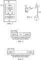
- FIGURE 1 is a block diagram depicting an electronic device 100 operating in accordance with an example embodiment of the invention.
- the electronic device 100 may also comprise non-volatile memory, which may be embedded and/or may be removable.
- the non-volatile memory may also comprise an electrically erasable programmable read only memory, flash memory, and/or the like.
- the processor 110 may comprise memory.
- the processor 110 may comprise volatile memory, non-volatile memory, and/or the like.
- the electronic device 100 may use at least one memory to store one or more computer program code 140.
- the processor 110 may perform embodiments of the present invention, or cause electronic device 100 to perform embodiments of the invention.
- the electronic device 100 may have a transmitter and a receiver.
- the transmitter and receiver are separated.
- the transmitter and receiver are combined.
- the receiver has a maximum radio frequency bandwidth it can receive data from.
- maximum radio frequency bandwidth it is meant a maximum width of a frequency band comprising carriers and gaps between the carriers.
- the processor 110 of the electronic device 100 may comprise circuitry for implementing audio feature, logic features, and/or the like.
- the processor 110 may comprise a digital signal processor device, a microprocessor device, a processing core, a digital to analog converter, other support circuits, and/or the like.
- control and signal processing features of the processor 110 may be allocated between devices, such as the devices describe above, according to their respective capabilities.
- the processor 110 may also comprise an internal voice coder and/or an internal data modem.
- the processor 110 may comprise features to operate one or more software programs.
- the processor 110 may be capable of operating a software program for connectivity, such as a conventional Internet browser.
- the connectivity program may allow the electronic device 100 to transmit and receive Internet content, such as location-based content, other web page content, and/or the like.
- the electronic device 100 may use a wireless application protocol, WAP,, hypertext transfer protocol, HTTP, file transfer protocol, FTP, and/or the like to transmit and/or receive the Internet content.
- the electronic device 100 may be capable of operating in accordance with any of a number of a first generation communication protocol, a second generation communication protocol, a third generation communication protocol, a fourth generation communication protocol, and/or the like.
- the electronic device 100 may be capable of operating in accordance with second generation, 2G, communication protocols IS-136, time division multiple access, TDMA, global system for mobile communication, GSM, IS-95 code division multiple access, CDMA, and/or the like.
- the electronic device 100 may be capable of operating in accordance with third-generation, 3G, communication protocols, such as Universal Mobile Telecommunications System, UMTS, CDMA2000, wideband CDMA, WCDMA, time division-synchronous CDMA, TD-SCDMA, and/or the like.
- the electronic device 100 may also be capable of operating in accordance with 3.9 generation, 3.9G, wireless communication protocols, such as Evolved Universal Terrestrial Radio Access Network, E-UTRAN, or the like, or wireless communication projects, such as long term evolution, LTE, or the like. Still further, the electronic device 100 may be capable of operating in accordance with fourth generation, 4G communication protocols.
- the electronic device 100 may be capable of operating in accordance with a non-cellular communication mechanism.
- the electronic device 100 may be capable of communication in a wireless local area network, WLAN, other communication networks, and/or the like.
- the electronic device 100 may communicate in accordance with techniques, such as radio frequency, RF, infrared, IrDA, any of a number of WLAN techniques.
- the electronic device 100 may communicate using one or more of the following WLAN techniques: IEEE 802.11, e.g., 802.11a, 802.11b, 802.11g, 802.11n, and/or the like.
- the electronic device 100 may also communicate, via a world interoperability, to use a microwave access, WiMAX technique, such as IEEE 802.16, and/or a wireless personal area network, WPAN technique, such as IEEE 802.15, BlueTooth, BT, ultra wideband, UWB, and/or the like.
- WiMAX such as IEEE 802.16, and/or a wireless personal area network, WPAN technique, such as IEEE 802.15, BlueTooth, BT, ultra wideband, UWB, and/or the like.
- the communications protocols described above may employ the use of signals.
- the signals comprises signaling information in accordance with the air interface standard of the applicable cellular or non-cellular system, user speech, received data, user generated data, and/or the like.
- the electronic device 100 may be capable of operating with one or more air interface standards, communication protocols, modulation types, access types, and/or the like. It should be further understood that the electronic device 100 is merely illustrative of one type of electronic device that would benefit from embodiments of the invention and, therefore, should not be taken to limit the scope of embodiments of the invention.
- While embodiments of the electronic device 100 are illustrated and will be hereinafter described for purposes of example, other types of electronic devices, such as a portable digital assistant, PDA, a pager, a mobile television, a gaming device, a camera, a video recorder, an audio player, a video player, a radio, a mobile telephone, a traditional computer, a portable computer device, a global positioning system, GPS, device, a GPS navigation device, a GPS system, a mobile computer, a browsing device, an electronic book reader, a combination thereof, and/or the like, may be used. While several embodiments of the invention may be performed or used by the electronic device 100, embodiments may also be employed by a server, a service, a combination thereof, and/or the like.
- FIGURE 2 illustrates an arrangement where some embodiments of the invention may be practiced.
- FIGURE 2 illustrates apparatus 210.
- Example of apparatus 210 may be an electronic device, such as electronic device 100 of FIGURE 1 .
- Connection 215 allows apparatus 210 to transmit information to base station 220. Connection 215 may also allow apparatus 210 to receive information from base station 220. Connection 215 may be a connection according to wideband code division multiple access, WCDMA, global system for mobile communications, GSM, long term evolution, LTE, or other wireless technology. In some embodiments connection 215 may be a wire-line connection instead of a wireless connection. Connection 215 may comprise an uplink connection for conveying information from apparatus 210 to base station 220. Connection 215 may comprise a downlink for conveying information from base station 220 to apparatus 210.
- Base station 220 comprises equipment configured to support connection 215, for example in embodiments where connection 215 is in accordance with WCDMA technology, base station 220 comprises at least equipment arranged to support WCDMA connections. Base station 220 is herein referred to as a base station, but is should be understood that in some embodiments, other terms such as access point 220 might be considered more accurate and such embodiments are not to be excluded from the scope of the present invention by this terminological
- Connection 215 may comprise resources reserved for the connection. Radio resources of a wireless connection 215 may comprise at least one of frequency, time, code or space resources, for example. Resources reserved for connection 215 may comprise a certain time-slice on a certain spreading code, which is used to spread a signal over a certain frequency band. In embodiments where connection 215 is wire-line, resources of the connection may comprise timeslots allocated to connection 215. Connection 215 may comprise encryption, authentication and charging aspects handled by the system in which base station 220 is comprised.
- connection 215 is in accordance with WCDMA technology
- 3 rd generation partnership project, 3GPP specifies the operating bands for full duplex division, FDD, operation.
- each carrier has a 5MHz bandwidth.
- the operating band allocation is merely illustrative of one type of allocations that may be used for WCDMA technology and, therefore, should not be taken to limit the scope of embodiments of the invention.
- Other operating band allocations may be possible for other technologies, such as LTE or LTE-Advanced.
- Table 1 An example of operating band allocations for WCDMA technology Operating Band UL Frequencies UE transmit, Node B receive DL frequencies UE receive, Node B transmit I 1920 - 1980 MHz 2110 -2170 MHz II 1850 -1910 MHz 1930 -1990 MHz III 1710-1785 MHz 1805-1880 MHz IV 1710-1755 MHz 2110-2155 MHz V 824 - 849 MHz 869-894 MHz VI 830-840 MHz 875-885 MHz VII 2500-2570 MHz 2620-2690 MHz VIII 880 - 915 MHz 925 - 960 MHz IX 1749.9-1784.9 MHz 1844.9-1879.9 MHz X 1710-1770 MHz 2110-2170 MHz XI 1427.9 - 1447.9 MHz 1475.9 - 1495.9 MHz XII 698 - 716 MHz 728 - 746 MHz XIII 777 - 787 MHz 746 - 756 MHz
- the multi-carriers available to apparatus 210 may not always be adjacent.
- the base station 220 may allocate non-adjacent carriers to apparatus 210.
- FIGURE 3 to FIGURE 6 provide some examples of non-adjacent carrier allocation.
- FIGURE 3 is a block diagram illustrating an allocation of two non-adjacent carriers for an apparatus with 15MHz maximum supported radio frequency bandwidth and 5MHz carrier bandwidth operating in accordance with an example embodiment of the invention.
- An example of the apparatus may be an electronic device, such as electronic device 100 of FIGURE 1 .
- the maximum gap size between non-adjacent carriers - carrier 1 and carrier 2 is 5MHz.
- FIGURE 4 is a block diagram illustrating an allocation of two non-adjacent carriers for an apparatus with 20MHz maximum supported radio frequency bandwidth and 5MHz carrier bandwidth operating in accordance with an example embodiment of the invention.
- An example of the apparatus may be an electronic device, such as electronic device 100 of FIGURE 1 .
- the maximum gap size between non-adjacent carriers - carrier 1 and carrier 2 is 10MHz.
- FIGURE 5 is a block diagram illustrating an allocation of three carriers for an apparatus with 20MHz maximum supported radio frequency bandwidth and 5MHz carrier bandwidth operating in accordance with an example embodiment of the invention.
- An example of the apparatus may be an electronic device, such as electronic device 100 of FIGURE 1 .
- the maximum gap size between any of the non-adjacent carriers is 5MHz.
- FIGURE 6 is a block diagram illustrating an allocation of three non-adjacent carriers for an apparatus with 25MHz maximum supported radio frequency bandwidth and 5MHz carrier bandwidth operating in accordance with an example embodiment of the invention.
- An example of the apparatus may be an electronic device, such as electronic device 100 of FIGURE 1 .
- the maximum gap size between any of the non-adjacent carriers is 5MHz.
- the carrier bandwidth is 5MHz.
- the 5MHz carrier bandwidth is merely illustrative of one type of allocations, and, therefore, should not be taken to limit the scope of embodiments of the invention.
- Other carrier bandwidth may be possible.
- the carrier bandwidth may be a fixed value or variant. For example, when the carrier bandwidths are variant, different carriers may have different carrier bandwidth values.
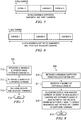
- FIGURE 7 is a flow diagram illustrating an example method for signaling and receiving data on non-adjacent carriers in accordance with an example embodiment of the invention.
- Example method 700 may be performed by or in an apparatus, such as electronic device 100 of FIGURE 1 .
- the apparatus reports a maximum radio frequency bandwidth it supports. Reporting may comprise transmitting a report message, for example using an uplink.
- the apparatus reports a number of carriers it supports. Reporting may comprise transmitting a report message, for example using an uplink.
- the apparatus receives data on non-adjacent carriers.
- the data on non-adjacent carriers may be received via a downlink, for example.
- the apparatus may further report a maximum gap size it supports between non-adjacent carriers.
- the example method 700 ends at block 713.
- the reporting in blocks 710 and 711 may be effected in a single message or in separate messages, depending on the embodiment.
- the number of supported carriers may also be reported before the maximum supported radio frequency bandwidth.
- the reporting and receiving of information illustrated in FIGURE 7 may take place over a suitable control channel or channels, or alternatively over at least one data channel.
- FIGURE 8 is a flow diagram illustrating an example method for allocating data on non-adjacent carriers in accordance with an example embodiment of the invention.
- Example method 800 may be performed by or in an apparatus, such as base station 220 of FIGURE 2 .
- the method may also be performed by or in other apparatuses, for example apparatuses comprised in a core network of a cellular network, or by a device comprised in a non-cellular network.
- the apparatus receives a maximum supported radio frequency bandwidth.
- the maximum supported radio frequency may be received via a message using uplink, for example.
- the apparatus receives a number of supported carriers.
- the number of supported carriers may be received via a message using uplink, for example.
- the apparatus allocates data on non-adjacent carriers.
- the allocation of data on non-adj acent carriers is determined based at least in part on the received maximum supported radio frequency bandwidth and the number of supported carriers. For example, in FIGURE 3 , when the received maximum supported radio frequency bandwidth is 15MHz and the number of supported carriers is two, the apparatus may allocate data on non-adjacent carrier 1 and carrier 2, and the maximum gap size between carrier 1 and 2 is 5MHz. In another example of FIGURE 4 , when the received maximum supported radio frequency bandwidth is 20MHz and the number of supported carriers is two, the apparatus may allocate data on non-adjacent carrier 1 and carrier 2, and the maximum gap size between carrier 1 and 2 may be 10MHz.
- data may be allocated on carriers 1 to carrier 3, where two of the carriers such as carrier 1 and carrier 2 may be non-adjacent and two carriers such as carrier 2 and carrier 3 are adjacent, and the maximum gap size between carrier 1 and 2 may be 10MHz.
- the apparatus may further receive a maximum supported gap size between non-adjacent carriers.
- the allocation of data on non-adj acent carriers is determined based at least in part on the received maximum supported radio frequency bandwidth and the number of supported carriers and the maximum supported gap size between non-adjacent carriers. For example, in FIGURE 6 , when the received maximum supported radio frequency bandwidth is 25MHz, the number of supported carriers is three and the maximum gap size between non-adjacent carriers is 5MHz, data may be allocated on carriers 1 to carrier 3, where carriers 1 to carrier 3 are non-adjacent, and the maximum gap size between any of the three carriers is 5MHz.
- the example method 800 ends at 813.
- the maximum supported radio frequency bandwidth is reported in a capability field.
- 3 rd generation partnership project 3GPP, specifies a user terminal capability field.
- each user terminal signals its radio capabilities that include a list of supported frequency bands.
- a user terminal may include an optional new "RF receiver bandwidth" information element, IE.
- the new information element may specify the value of maximum supported radio frequency bandwidth.
- the new information element may also indicate that a user terminal may work in non-adjacent carrier mode.
- a user terminal capability field is herein referred to as capability field, but it should be understood that in some embodiments, other name of the field may be used and such embodiments are not to be excluded from the scope of the present invention by this terminological choice.
- the apparatus 210 from FIGURE 2 may further report a maximum supported gap size between non-adjacent carriers.
- An optional new "Maximum gap size" information element, IE may be included in the capability field. The new information element may specify the value of maximum supported gap size between non-adjacent carriers.
- TABLE 3 An example of reporting maximum supported radio frequency bandwidth and maximum supported gap size between non-adjacent carriers Frequency band specific capability list MP 1.. ⁇ maxFreq > > Frequency band MP Enumerated > Frequency band 2 OP Enumerated Rel-6 .].
- the apparatus 210 of FIGURE 2 may support multiple frequency bands. In an example embodiment, the apparatus 210 may report the maximum radio frequency bandwidth, the number of supported carriers and/or the maximum gap size for each supported frequency band.
- Embodiments of the present invention may be implemented in software, hardware, application logic or a combination of software, hardware and application logic.
- the software, application logic and/or hardware may reside on an electronic device or a personal key. If desired, part of the software, application logic and/or hardware may reside on an electronic device and part of the software, application logic and/or hardware may reside on a personal key.
- the application logic, software or an instruction set is maintained on any one of various conventional computer-readable media.
- a "computer-readable medium" may be any media or means that can contain, store, communicate, propagate or transport the instructions for use by or in connection with an instruction execution system, apparatus, or device.
- a computer-readable medium may comprise a computer-readable storage medium, for example a non-transitory computer-readable storage medium, that may be any media or means that can contain or store the instructions for use by or in connection with an instruction execution system, apparatus, or device.
- the different functions discussed herein may be performed in a different order and/or concurrently with each other. Furthermore, if desired, one or more of the above-described functions may be optional or may be combined.
Landscapes
- Engineering & Computer Science (AREA)
- Signal Processing (AREA)
- Computer Networks & Wireless Communication (AREA)
- Quality & Reliability (AREA)
- Mobile Radio Communication Systems (AREA)
Claims (12)
- Verfahren, umfassend:Berichten einer maximal unterstützten Funkfrequenzbandbreite;Berichten einer Anzahl unterstützter Träger;Berichten einer maximal unterstützten Zwischenraumgröße zwischen nicht benachbarten Trägern; undEmpfangen von Daten auf nicht benachbarten Trägern, wobei die nicht benachbarten Träger zumindest teilweise auf der Grundlage der berichteten maximal unterstützten Funkfrequenzbandbreite, der berichteten maximal unterstützten Zwischenraumgröße und der berichteten Anzahl unterstützter Träger bestimmt werden.
- Verfahren, umfassend:Empfangen einer maximal unterstützten Funkfrequenzbandbreite;Empfangen einer Anzahl unterstützter Träger;Empfangen einer maximal unterstützten Zwischenraumgröße zwischen nicht benachbarten Trägern; undZuweisen von Daten auf nicht benachbarten Trägern, wobei die nicht benachbarten Träger zumindest teilweise auf der Grundlage der empfangenen maximal unterstützten Funkfrequenzbandbreite, der empfangenen maximal unterstützten Zwischenraumgröße und der empfangenen Anzahl unterstützter Träger bestimmt werden.
- Vorrichtung, umfassend:mindestens einen Prozessor; undmindestens einen Speicher einschließlich Computerprogrammcode,wobei der mindestens eine Speicher und der Computerprogrammcode dafür ausgelegt sind, mit dem mindestens einen Prozessor die Vorrichtung zu veranlassen, zumindest das Folgende auszuführen:Berichten einer maximal unterstützten Funkfrequenzbandbreite;Berichten einer Anzahl unterstützter Träger;Berichten einer maximal unterstützten Zwischenraumgröße zwischen nicht benachbarten Trägern; undEmpfangen von Daten auf nicht benachbarten Trägern, wobei die nicht benachbarten Träger zumindest teilweise auf der Grundlage der berichteten maximal unterstützten Funkfrequenzbandbreite, der berichteten maximal unterstützten Zwischenraumgröße und der berichteten Anzahl unterstützter Träger bestimmt werden.
- Vorrichtung nach Anspruch 3, wobei das Berichten der maximal unterstützten Funkfrequenzbandbreite das Berichten der maximal unterstützten Funkfrequenzbandbreite für jedes unterstützte Band umfasst.
- Vorrichtung nach Anspruch 3, wobei das Berichten der Anzahl unterstützter Träger das Berichten der Anzahl unterstützter Träger für jedes unterstützte Band umfasst.
- Vorrichtung nach Anspruch 3, wobei die maximal unterstützte Funkfrequenzbandbreite in einem Fähigkeitsfeld berichtet wird.
- Vorrichtung, umfassend:mindestens einen Prozessor; undmindestens einen Speicher einschließlich Computerprogrammcode, wobei der mindestens eine Speicher und der Computerprogrammcode dafür ausgelegt sind, mit dem mindestens einen Prozessor die Vorrichtung zu veranlassen, zumindest das Folgende auszuführen:Empfangen einer maximal unterstützten Funkfrequenzbandbreite;Empfangen einer Anzahl unterstützter Träger;Empfangen einer maximal unterstützten Zwischenraumgröße zwischen nicht benachbarten Trägern; undZuweisen von Daten auf nicht benachbarten Trägern, wobei die nicht benachbarten Träger zumindest teilweise auf der Grundlage der empfangenen maximal unterstützten Funkfrequenzbandbreite, der empfangenen maximal unterstützten Zwischenraumgröße und der empfangenen Anzahl unterstützter Träger bestimmt werden.
- Vorrichtung nach Anspruch 7, wobei das Empfangen der maximal unterstützten Funkfrequenzbandbreite das Empfangen der maximal unterstützten Funkfrequenzbandbreite für jedes unterstützte Band umfasst.
- Vorrichtung nach Anspruch 7, wobei das Empfangen der Anzahl unterstützter Träger das Empfangen der Anzahl unterstützter Träger für jedes unterstützte Band umfasst.
- Vorrichtung nach Anspruch 7, wobei die maximal unterstützte Funkfrequenzbandbreite in einem Fähigkeitsfeld empfangen wird.
- Computerprogrammprodukt, umfassend ein computerlesbares Medium mit einem darin verkörperten Computerprogrammcode zur Verwendung mit einem Computer, wobei der Computerprogrammcode umfasst:Code zum Berichten einer maximal unterstützten Funkfrequenzbandbreite;Code zum Berichten einer Anzahl unterstützter Träger;Code zum Berichten einer maximal unterstützten Zwischenraumgröße zwischen nicht benachbarten Trägern; undCode zum Empfangen von Daten auf nicht benachbarten Trägern, wobei die nicht benachbarten Träger zumindest teilweise auf der Grundlage der berichteten maximal unterstützten Funkfrequenzbandbreite, der berichteten maximal unterstützten Zwischenraumgröße und der berichteten Anzahl unterstützter Träger bestimmt werden.
- Computerprogrammprodukt, umfassend ein computerlesbares Medium mit einem darin verkörperten Computerprogrammcode zur Verwendung mit einem Computer, wobei der Computerprogrammcode umfasst:Code zum Empfangen einer maximal unterstützten Funkfrequenzbandbreite;Code zum Empfangen einer Anzahl unterstützter Träger;Code zum Empfangen einer maximal unterstützten Zwischenraumgröße zwischen nicht benachbarten Trägern;undCode zum Zuweisen von Daten auf nicht benachbarten Trägern, wobei die nicht benachbarten Träger zumindest teilweise auf der Grundlage der empfangenen maximal unterstützten Funkfrequenzbandbreite, der empfangenen maximal unterstützten Zwischenraumgröße und der empfangenen Anzahl unterstützter Träger bestimmt werden.
Applications Claiming Priority (1)
| Application Number | Priority Date | Filing Date | Title |
|---|---|---|---|
| PCT/IB2011/050123 WO2012095699A1 (en) | 2011-01-11 | 2011-01-11 | Method and apparatus for non-adjacent carrier signalling in a multicarrier broadband wireless system |
Publications (3)
| Publication Number | Publication Date |
|---|---|
| EP2664205A1 EP2664205A1 (de) | 2013-11-20 |
| EP2664205A4 EP2664205A4 (de) | 2017-08-02 |
| EP2664205B1 true EP2664205B1 (de) | 2020-07-29 |
Family
ID=46506800
Family Applications (1)
| Application Number | Title | Priority Date | Filing Date |
|---|---|---|---|
| EP11855373.4A Active EP2664205B1 (de) | 2011-01-11 | 2011-01-11 | Verfahren und vorrichtungen für eine signalisierung nicht-benachbarter träger in einem drahtlosen mehrträgerbreitbandsystem |
Country Status (12)
| Country | Link |
|---|---|
| US (1) | US10177891B2 (de) |
| EP (1) | EP2664205B1 (de) |
| JP (1) | JP5756868B2 (de) |
| KR (1) | KR101492409B1 (de) |
| CN (1) | CN103404216B (de) |
| AU (4) | AU2011355135A1 (de) |
| BR (1) | BR112013017793B1 (de) |
| CA (1) | CA2824008C (de) |
| ES (1) | ES2828501T3 (de) |
| MX (1) | MX2013008037A (de) |
| TW (1) | TWI442791B (de) |
| WO (1) | WO2012095699A1 (de) |
Families Citing this family (7)
| Publication number | Priority date | Publication date | Assignee | Title |
|---|---|---|---|---|
| CN103503545B (zh) * | 2011-05-03 | 2017-09-19 | 瑞典爱立信有限公司 | 网络节点、用户设备及针对下行链路操作配置小区的方法 |
| US9955329B2 (en) * | 2014-07-28 | 2018-04-24 | Nec Corporation | Mobile wireless communication system |
| GB2537803B (en) * | 2015-02-19 | 2017-11-15 | Canon Kk | Non-Contiguous channel allocation over multi-channel wireless networks |
| CN106162906B (zh) * | 2015-03-31 | 2019-01-15 | 中兴通讯股份有限公司 | 调度信息发送、接收方法及装置 |
| WO2016183950A1 (zh) * | 2015-05-15 | 2016-11-24 | 华为技术有限公司 | 载波聚合能力上报、载波测量装置及方法 |
| WO2017180751A1 (en) * | 2016-04-12 | 2017-10-19 | Marvell Semiconductor, Inc. | Reporting bandwidth capability of a bandwidth-limited communication device |
| US20240113845A1 (en) * | 2022-09-29 | 2024-04-04 | Apple Inc. | Apparatus and method for indicating carrier aggregation capability |
Family Cites Families (18)
| Publication number | Priority date | Publication date | Assignee | Title |
|---|---|---|---|---|
| US7406261B2 (en) | 1999-11-02 | 2008-07-29 | Lot 41 Acquisition Foundation, Llc | Unified multi-carrier framework for multiple-access technologies |
| US7046618B2 (en) | 2003-11-25 | 2006-05-16 | Pulse-Link, Inc. | Bridged ultra-wideband communication method and apparatus |
| US8009035B1 (en) | 2007-03-01 | 2011-08-30 | Darren M Vallaire | Alert warning system |
| CN101136894B (zh) | 2007-03-23 | 2012-11-28 | 中兴通讯股份有限公司 | 可扩展的ofdm及ofdma带宽分配的方法和系统 |
| CN101350941B (zh) | 2007-07-18 | 2011-06-15 | 电信科学技术研究院 | 提供高速上行分组业务的网络服务控制方法、装置及系统 |
| CN101483914B (zh) | 2008-01-11 | 2010-12-08 | 中兴通讯股份有限公司 | 一种利用非连续的多载波传输用户数据的方法 |
| JP5086880B2 (ja) | 2008-04-22 | 2012-11-28 | シャープ株式会社 | 送信装置、受信装置及び無線通信システム |
| CN101778393B (zh) | 2009-01-09 | 2012-07-25 | 电信科学技术研究院 | 载波聚合系统及其频谱碎片处理方法、设备 |
| JP5422211B2 (ja) * | 2009-01-21 | 2014-02-19 | 株式会社日立製作所 | 無線通信システム、端末及び基地局 |
| WO2010118582A1 (zh) * | 2009-04-17 | 2010-10-21 | 华为技术有限公司 | 一种下行小区间干扰协调方法和基站 |
| CN103974432B (zh) * | 2009-04-24 | 2017-11-17 | 联发科技股份有限公司 | 载波分配方法和移动站 |
| EP3182775A1 (de) * | 2009-06-17 | 2017-06-21 | IDTP Holdings, Inc. | Planung der datenübertragung zwischen einem mobilen endgerät und einer basisstation in einem drahtloskommunikationsnetzwerk |
| US8958376B2 (en) * | 2009-06-17 | 2015-02-17 | Telefonaktiebolaget L M Ericsson (Publ) | Scheduling data transmissions between a mobile terminal and a base station in a wireless communications network |
| EP2317815A1 (de) * | 2009-11-02 | 2011-05-04 | Panasonic Corporation | Leistungsgrenzenmeldung in einem Carrier-Aggregation-Kommunikationssystem |
| EP2824866B1 (de) * | 2009-12-14 | 2016-06-22 | Telefonaktiebolaget LM Ericsson (publ) | Verfahren und Vorrichtungen zur Datenübertragung über mehrere Träger |
| KR20110081017A (ko) * | 2010-01-05 | 2011-07-13 | 주식회사 팬택 | 무선통신 시스템에서 자원할당전송방법 및 그 송신장치, 이에 대응하는 수신장치 |
| CN102378370B (zh) * | 2010-08-13 | 2014-10-29 | 电信科学技术研究院 | 一种载波聚合能力的处理方法和设备 |
| GB2491887B (en) * | 2011-06-16 | 2014-04-16 | Broadcom Corp | Multicarrier communication support |
-
2011
- 2011-01-11 EP EP11855373.4A patent/EP2664205B1/de active Active
- 2011-01-11 BR BR112013017793-4A patent/BR112013017793B1/pt active IP Right Grant
- 2011-01-11 MX MX2013008037A patent/MX2013008037A/es active IP Right Grant
- 2011-01-11 CA CA2824008A patent/CA2824008C/en active Active
- 2011-01-11 CN CN201180069199.8A patent/CN103404216B/zh active Active
- 2011-01-11 JP JP2013548897A patent/JP5756868B2/ja active Active
- 2011-01-11 US US13/979,183 patent/US10177891B2/en active Active
- 2011-01-11 WO PCT/IB2011/050123 patent/WO2012095699A1/en not_active Ceased
- 2011-01-11 ES ES11855373T patent/ES2828501T3/es active Active
- 2011-01-11 KR KR20137020899A patent/KR101492409B1/ko active Active
- 2011-01-11 AU AU2011355135A patent/AU2011355135A1/en not_active Abandoned
-
2012
- 2012-01-09 TW TW101100773A patent/TWI442791B/zh active
-
2016
- 2016-11-01 AU AU2016253552A patent/AU2016253552A1/en not_active Abandoned
-
2018
- 2018-11-22 AU AU2018267644A patent/AU2018267644A1/en not_active Abandoned
-
2020
- 2020-12-17 AU AU2020289808A patent/AU2020289808B2/en active Active
Non-Patent Citations (1)
| Title |
|---|
| None * |
Also Published As
| Publication number | Publication date |
|---|---|
| WO2012095699A1 (en) | 2012-07-19 |
| EP2664205A4 (de) | 2017-08-02 |
| US10177891B2 (en) | 2019-01-08 |
| TW201236476A (en) | 2012-09-01 |
| CA2824008C (en) | 2019-04-23 |
| KR101492409B1 (ko) | 2015-02-12 |
| CN103404216A (zh) | 2013-11-20 |
| JP2014509105A (ja) | 2014-04-10 |
| BR112013017793A2 (pt) | 2016-10-11 |
| BR112013017793B1 (pt) | 2022-01-11 |
| EP2664205A1 (de) | 2013-11-20 |
| CN103404216B (zh) | 2018-08-17 |
| ES2828501T3 (es) | 2021-05-26 |
| MX2013008037A (es) | 2013-09-16 |
| JP5756868B2 (ja) | 2015-07-29 |
| KR20130116919A (ko) | 2013-10-24 |
| AU2020289808B2 (en) | 2022-10-27 |
| TWI442791B (zh) | 2014-06-21 |
| AU2020289808A1 (en) | 2021-01-21 |
| AU2011355135A1 (en) | 2013-07-25 |
| AU2018267644A1 (en) | 2018-12-13 |
| AU2016253552A1 (en) | 2016-11-17 |
| CA2824008A1 (en) | 2012-07-19 |
| US20140016587A1 (en) | 2014-01-16 |
Similar Documents
| Publication | Publication Date | Title |
|---|---|---|
| AU2020289808B2 (en) | Method and apparatus for non-adjacent carrier signalling in a multicarrier broadband wireless system | |
| US12369065B2 (en) | Carrier aggregation capability signaling | |
| CN102378370B (zh) | 一种载波聚合能力的处理方法和设备 | |
| EP3603176B9 (de) | Techniken für doppelmodus-operationen in neuem radio | |
| CN111436089B (zh) | 通信的方法和装置 | |
| JP2017523648A (ja) | 未認可lteネットワークのためのグループ搬送波スケジューリング | |
| WO2021146867A1 (zh) | 一种跳频方法、电子设备及存储介质 | |
| CN101808402B (zh) | 成员载波信息的获取方法、及成员载波信息的收发系统 | |
| CN105790907A (zh) | 频带修改方法、装置、终端及基站 | |
| CN118975375A (zh) | 用于多个载波上的频域资源分配的方法及设备 | |
| CN116420412B (zh) | 用于lte和5g nr动态频谱共享的调度限制增强的方法、装置和基站 | |
| CN104113505B (zh) | 多载波通信系统降低干扰的方法以及终端设备 | |
| CN120035953A (zh) | 用于在无线通信中发送重复的技术 | |
| CN116711409A (zh) | 一种bwp的确定方法及装置 | |
| HK1190859A (en) | Method and apparatus for non-adjacent carrier signalling in a multicarrier broadband wireless system | |
| HK1190859B (zh) | 在多载波宽带无线系统中非相邻载波信令化的方法和装置 | |
| WO2025026696A1 (en) | Apparatus, method, and computer program | |
| CN119896011A (zh) | 用于多小区调度场景中的频域资源指示的方法及设备 | |
| HK40016515B (en) | Techniques for dual-mode operations in new radio | |
| HK40016515A (en) | Techniques for dual-mode operations in new radio |
Legal Events
| Date | Code | Title | Description |
|---|---|---|---|
| PUAI | Public reference made under article 153(3) epc to a published international application that has entered the european phase |
Free format text: ORIGINAL CODE: 0009012 |
|
| 17P | Request for examination filed |
Effective date: 20130812 |
|
| AK | Designated contracting states |
Kind code of ref document: A1 Designated state(s): AL AT BE BG CH CY CZ DE DK EE ES FI FR GB GR HR HU IE IS IT LI LT LU LV MC MK MT NL NO PL PT RO RS SE SI SK SM TR |
|
| DAX | Request for extension of the european patent (deleted) | ||
| RA4 | Supplementary search report drawn up and despatched (corrected) |
Effective date: 20170629 |
|
| RIC1 | Information provided on ipc code assigned before grant |
Ipc: H04W 72/04 20090101AFI20170623BHEP Ipc: H04L 5/00 20060101ALI20170623BHEP |
|
| STAA | Information on the status of an ep patent application or granted ep patent |
Free format text: STATUS: EXAMINATION IS IN PROGRESS |
|
| 17Q | First examination report despatched |
Effective date: 20190226 |
|
| RAP1 | Party data changed (applicant data changed or rights of an application transferred) |
Owner name: NOKIA SOLUTIONS AND NETWORKS OY |
|
| GRAP | Despatch of communication of intention to grant a patent |
Free format text: ORIGINAL CODE: EPIDOSNIGR1 |
|
| STAA | Information on the status of an ep patent application or granted ep patent |
Free format text: STATUS: GRANT OF PATENT IS INTENDED |
|
| RIC1 | Information provided on ipc code assigned before grant |
Ipc: H04W 72/04 20090101AFI20200107BHEP Ipc: H04W 88/06 20090101ALN20200107BHEP Ipc: H04L 5/00 20060101ALI20200107BHEP Ipc: H04L 27/26 20060101ALN20200107BHEP |
|
| INTG | Intention to grant announced |
Effective date: 20200127 |
|
| GRAJ | Information related to disapproval of communication of intention to grant by the applicant or resumption of examination proceedings by the epo deleted |
Free format text: ORIGINAL CODE: EPIDOSDIGR1 |
|
| STAA | Information on the status of an ep patent application or granted ep patent |
Free format text: STATUS: EXAMINATION IS IN PROGRESS |
|
| GRAR | Information related to intention to grant a patent recorded |
Free format text: ORIGINAL CODE: EPIDOSNIGR71 |
|
| GRAS | Grant fee paid |
Free format text: ORIGINAL CODE: EPIDOSNIGR3 |
|
| STAA | Information on the status of an ep patent application or granted ep patent |
Free format text: STATUS: GRANT OF PATENT IS INTENDED |
|
| GRAA | (expected) grant |
Free format text: ORIGINAL CODE: 0009210 |
|
| STAA | Information on the status of an ep patent application or granted ep patent |
Free format text: STATUS: THE PATENT HAS BEEN GRANTED |
|
| INTC | Intention to grant announced (deleted) | ||
| RIC1 | Information provided on ipc code assigned before grant |
Ipc: H04W 72/04 20090101AFI20200604BHEP Ipc: H04L 5/00 20060101ALI20200604BHEP Ipc: H04L 27/26 20060101ALN20200604BHEP Ipc: H04W 88/06 20090101ALN20200604BHEP |
|
| INTG | Intention to grant announced |
Effective date: 20200617 |
|
| AK | Designated contracting states |
Kind code of ref document: B1 Designated state(s): AL AT BE BG CH CY CZ DE DK EE ES FI FR GB GR HR HU IE IS IT LI LT LU LV MC MK MT NL NO PL PT RO RS SE SI SK SM TR |
|
| REG | Reference to a national code |
Ref country code: GB Ref legal event code: FG4D |
|
| REG | Reference to a national code |
Ref country code: CH Ref legal event code: EP |
|
| REG | Reference to a national code |
Ref country code: AT Ref legal event code: REF Ref document number: 1297315 Country of ref document: AT Kind code of ref document: T Effective date: 20200815 |
|
| REG | Reference to a national code |
Ref country code: IE Ref legal event code: FG4D |
|
| REG | Reference to a national code |
Ref country code: DE Ref legal event code: R096 Ref document number: 602011068021 Country of ref document: DE |
|
| REG | Reference to a national code |
Ref country code: FI Ref legal event code: FGE |
|
| REG | Reference to a national code |
Ref country code: NL Ref legal event code: FP |
|
| REG | Reference to a national code |
Ref country code: SE Ref legal event code: TRGR |
|
| REG | Reference to a national code |
Ref country code: LT Ref legal event code: MG4D |
|
| REG | Reference to a national code |
Ref country code: AT Ref legal event code: MK05 Ref document number: 1297315 Country of ref document: AT Kind code of ref document: T Effective date: 20200729 |
|
| PG25 | Lapsed in a contracting state [announced via postgrant information from national office to epo] |
Ref country code: AT Free format text: LAPSE BECAUSE OF FAILURE TO SUBMIT A TRANSLATION OF THE DESCRIPTION OR TO PAY THE FEE WITHIN THE PRESCRIBED TIME-LIMIT Effective date: 20200729 Ref country code: GR Free format text: LAPSE BECAUSE OF FAILURE TO SUBMIT A TRANSLATION OF THE DESCRIPTION OR TO PAY THE FEE WITHIN THE PRESCRIBED TIME-LIMIT Effective date: 20201030 Ref country code: PT Free format text: LAPSE BECAUSE OF FAILURE TO SUBMIT A TRANSLATION OF THE DESCRIPTION OR TO PAY THE FEE WITHIN THE PRESCRIBED TIME-LIMIT Effective date: 20201130 Ref country code: HR Free format text: LAPSE BECAUSE OF FAILURE TO SUBMIT A TRANSLATION OF THE DESCRIPTION OR TO PAY THE FEE WITHIN THE PRESCRIBED TIME-LIMIT Effective date: 20200729 Ref country code: LT Free format text: LAPSE BECAUSE OF FAILURE TO SUBMIT A TRANSLATION OF THE DESCRIPTION OR TO PAY THE FEE WITHIN THE PRESCRIBED TIME-LIMIT Effective date: 20200729 Ref country code: BG Free format text: LAPSE BECAUSE OF FAILURE TO SUBMIT A TRANSLATION OF THE DESCRIPTION OR TO PAY THE FEE WITHIN THE PRESCRIBED TIME-LIMIT Effective date: 20201029 Ref country code: NO Free format text: LAPSE BECAUSE OF FAILURE TO SUBMIT A TRANSLATION OF THE DESCRIPTION OR TO PAY THE FEE WITHIN THE PRESCRIBED TIME-LIMIT Effective date: 20201029 |
|
| PG25 | Lapsed in a contracting state [announced via postgrant information from national office to epo] |
Ref country code: IS Free format text: LAPSE BECAUSE OF FAILURE TO SUBMIT A TRANSLATION OF THE DESCRIPTION OR TO PAY THE FEE WITHIN THE PRESCRIBED TIME-LIMIT Effective date: 20201129 Ref country code: LV Free format text: LAPSE BECAUSE OF FAILURE TO SUBMIT A TRANSLATION OF THE DESCRIPTION OR TO PAY THE FEE WITHIN THE PRESCRIBED TIME-LIMIT Effective date: 20200729 Ref country code: RS Free format text: LAPSE BECAUSE OF FAILURE TO SUBMIT A TRANSLATION OF THE DESCRIPTION OR TO PAY THE FEE WITHIN THE PRESCRIBED TIME-LIMIT Effective date: 20200729 Ref country code: PL Free format text: LAPSE BECAUSE OF FAILURE TO SUBMIT A TRANSLATION OF THE DESCRIPTION OR TO PAY THE FEE WITHIN THE PRESCRIBED TIME-LIMIT Effective date: 20200729 |
|
| PG25 | Lapsed in a contracting state [announced via postgrant information from national office to epo] |
Ref country code: SM Free format text: LAPSE BECAUSE OF FAILURE TO SUBMIT A TRANSLATION OF THE DESCRIPTION OR TO PAY THE FEE WITHIN THE PRESCRIBED TIME-LIMIT Effective date: 20200729 Ref country code: RO Free format text: LAPSE BECAUSE OF FAILURE TO SUBMIT A TRANSLATION OF THE DESCRIPTION OR TO PAY THE FEE WITHIN THE PRESCRIBED TIME-LIMIT Effective date: 20200729 Ref country code: CZ Free format text: LAPSE BECAUSE OF FAILURE TO SUBMIT A TRANSLATION OF THE DESCRIPTION OR TO PAY THE FEE WITHIN THE PRESCRIBED TIME-LIMIT Effective date: 20200729 Ref country code: DK Free format text: LAPSE BECAUSE OF FAILURE TO SUBMIT A TRANSLATION OF THE DESCRIPTION OR TO PAY THE FEE WITHIN THE PRESCRIBED TIME-LIMIT Effective date: 20200729 Ref country code: EE Free format text: LAPSE BECAUSE OF FAILURE TO SUBMIT A TRANSLATION OF THE DESCRIPTION OR TO PAY THE FEE WITHIN THE PRESCRIBED TIME-LIMIT Effective date: 20200729 |
|
| REG | Reference to a national code |
Ref country code: DE Ref legal event code: R097 Ref document number: 602011068021 Country of ref document: DE |
|
| REG | Reference to a national code |
Ref country code: ES Ref legal event code: FG2A Ref document number: 2828501 Country of ref document: ES Kind code of ref document: T3 Effective date: 20210526 |
|
| PG25 | Lapsed in a contracting state [announced via postgrant information from national office to epo] |
Ref country code: AL Free format text: LAPSE BECAUSE OF FAILURE TO SUBMIT A TRANSLATION OF THE DESCRIPTION OR TO PAY THE FEE WITHIN THE PRESCRIBED TIME-LIMIT Effective date: 20200729 |
|
| PLBE | No opposition filed within time limit |
Free format text: ORIGINAL CODE: 0009261 |
|
| STAA | Information on the status of an ep patent application or granted ep patent |
Free format text: STATUS: NO OPPOSITION FILED WITHIN TIME LIMIT |
|
| PG25 | Lapsed in a contracting state [announced via postgrant information from national office to epo] |
Ref country code: SK Free format text: LAPSE BECAUSE OF FAILURE TO SUBMIT A TRANSLATION OF THE DESCRIPTION OR TO PAY THE FEE WITHIN THE PRESCRIBED TIME-LIMIT Effective date: 20200729 |
|
| 26N | No opposition filed |
Effective date: 20210430 |
|
| PG25 | Lapsed in a contracting state [announced via postgrant information from national office to epo] |
Ref country code: MC Free format text: LAPSE BECAUSE OF FAILURE TO SUBMIT A TRANSLATION OF THE DESCRIPTION OR TO PAY THE FEE WITHIN THE PRESCRIBED TIME-LIMIT Effective date: 20200729 Ref country code: SI Free format text: LAPSE BECAUSE OF FAILURE TO SUBMIT A TRANSLATION OF THE DESCRIPTION OR TO PAY THE FEE WITHIN THE PRESCRIBED TIME-LIMIT Effective date: 20200729 |
|
| REG | Reference to a national code |
Ref country code: CH Ref legal event code: PL |
|
| PG25 | Lapsed in a contracting state [announced via postgrant information from national office to epo] |
Ref country code: LU Free format text: LAPSE BECAUSE OF NON-PAYMENT OF DUE FEES Effective date: 20210111 |
|
| REG | Reference to a national code |
Ref country code: BE Ref legal event code: MM Effective date: 20210131 |
|
| PG25 | Lapsed in a contracting state [announced via postgrant information from national office to epo] |
Ref country code: LI Free format text: LAPSE BECAUSE OF NON-PAYMENT OF DUE FEES Effective date: 20210131 Ref country code: CH Free format text: LAPSE BECAUSE OF NON-PAYMENT OF DUE FEES Effective date: 20210131 |
|
| PG25 | Lapsed in a contracting state [announced via postgrant information from national office to epo] |
Ref country code: IE Free format text: LAPSE BECAUSE OF NON-PAYMENT OF DUE FEES Effective date: 20210111 |
|
| PG25 | Lapsed in a contracting state [announced via postgrant information from national office to epo] |
Ref country code: BE Free format text: LAPSE BECAUSE OF NON-PAYMENT OF DUE FEES Effective date: 20210131 |
|
| PG25 | Lapsed in a contracting state [announced via postgrant information from national office to epo] |
Ref country code: HU Free format text: LAPSE BECAUSE OF FAILURE TO SUBMIT A TRANSLATION OF THE DESCRIPTION OR TO PAY THE FEE WITHIN THE PRESCRIBED TIME-LIMIT; INVALID AB INITIO Effective date: 20110111 Ref country code: CY Free format text: LAPSE BECAUSE OF FAILURE TO SUBMIT A TRANSLATION OF THE DESCRIPTION OR TO PAY THE FEE WITHIN THE PRESCRIBED TIME-LIMIT Effective date: 20200729 |
|
| P01 | Opt-out of the competence of the unified patent court (upc) registered |
Effective date: 20230527 |
|
| PG25 | Lapsed in a contracting state [announced via postgrant information from national office to epo] |
Ref country code: MK Free format text: LAPSE BECAUSE OF FAILURE TO SUBMIT A TRANSLATION OF THE DESCRIPTION OR TO PAY THE FEE WITHIN THE PRESCRIBED TIME-LIMIT Effective date: 20200729 |
|
| PG25 | Lapsed in a contracting state [announced via postgrant information from national office to epo] |
Ref country code: TR Free format text: LAPSE BECAUSE OF FAILURE TO SUBMIT A TRANSLATION OF THE DESCRIPTION OR TO PAY THE FEE WITHIN THE PRESCRIBED TIME-LIMIT Effective date: 20200729 |
|
| PG25 | Lapsed in a contracting state [announced via postgrant information from national office to epo] |
Ref country code: MT Free format text: LAPSE BECAUSE OF FAILURE TO SUBMIT A TRANSLATION OF THE DESCRIPTION OR TO PAY THE FEE WITHIN THE PRESCRIBED TIME-LIMIT Effective date: 20200729 |
|
| PGFP | Annual fee paid to national office [announced via postgrant information from national office to epo] |
Ref country code: DE Payment date: 20241203 Year of fee payment: 15 |
|
| PGFP | Annual fee paid to national office [announced via postgrant information from national office to epo] |
Ref country code: ES Payment date: 20250206 Year of fee payment: 15 |
|
| PGFP | Annual fee paid to national office [announced via postgrant information from national office to epo] |
Ref country code: IT Payment date: 20241210 Year of fee payment: 15 |
|
| PGFP | Annual fee paid to national office [announced via postgrant information from national office to epo] |
Ref country code: GB Payment date: 20251204 Year of fee payment: 16 |
|
| PGFP | Annual fee paid to national office [announced via postgrant information from national office to epo] |
Ref country code: FI Payment date: 20251230 Year of fee payment: 16 |
|
| PGFP | Annual fee paid to national office [announced via postgrant information from national office to epo] |
Ref country code: NL Payment date: 20251215 Year of fee payment: 16 Ref country code: FR Payment date: 20251208 Year of fee payment: 16 |
|
| PGFP | Annual fee paid to national office [announced via postgrant information from national office to epo] |
Ref country code: SE Payment date: 20251210 Year of fee payment: 16 |