EP2664196B1 - Batterieleistungsüberwachung und audiosignaldämpfung - Google Patents
Batterieleistungsüberwachung und audiosignaldämpfung Download PDFInfo
- Publication number
- EP2664196B1 EP2664196B1 EP12701790.3A EP12701790A EP2664196B1 EP 2664196 B1 EP2664196 B1 EP 2664196B1 EP 12701790 A EP12701790 A EP 12701790A EP 2664196 B1 EP2664196 B1 EP 2664196B1
- Authority
- EP
- European Patent Office
- Prior art keywords
- audio signal
- battery voltage
- attenuation
- threshold
- voltage level
- Prior art date
- Legal status (The legal status is an assumption and is not a legal conclusion. Google has not performed a legal analysis and makes no representation as to the accuracy of the status listed.)
- Active
Links
Images





Classifications
-
- H—ELECTRICITY
- H04—ELECTRIC COMMUNICATION TECHNIQUE
- H04W—WIRELESS COMMUNICATION NETWORKS
- H04W52/00—Power management, e.g. Transmission Power Control [TPC] or power classes
- H04W52/02—Power saving arrangements
- H04W52/0209—Power saving arrangements in terminal devices
- H04W52/0261—Power saving arrangements in terminal devices managing power supply demand, e.g. depending on battery level
- H04W52/0267—Power saving arrangements in terminal devices managing power supply demand, e.g. depending on battery level by controlling user interface components
-
- G—PHYSICS
- G06—COMPUTING OR CALCULATING; COUNTING
- G06F—ELECTRIC DIGITAL DATA PROCESSING
- G06F1/00—Details not covered by groups G06F3/00 - G06F13/00 and G06F21/00
- G06F1/26—Power supply means, e.g. regulation thereof
- G06F1/32—Means for saving power
-
- G—PHYSICS
- G06—COMPUTING OR CALCULATING; COUNTING
- G06F—ELECTRIC DIGITAL DATA PROCESSING
- G06F1/00—Details not covered by groups G06F3/00 - G06F13/00 and G06F21/00
- G06F1/26—Power supply means, e.g. regulation thereof
- G06F1/32—Means for saving power
- G06F1/3203—Power management, i.e. event-based initiation of a power-saving mode
- G06F1/3206—Monitoring of events, devices or parameters that trigger a change in power modality
- G06F1/3212—Monitoring battery levels, e.g. power saving mode being initiated when battery voltage goes below a certain level
-
- G—PHYSICS
- G06—COMPUTING OR CALCULATING; COUNTING
- G06F—ELECTRIC DIGITAL DATA PROCESSING
- G06F1/00—Details not covered by groups G06F3/00 - G06F13/00 and G06F21/00
- G06F1/26—Power supply means, e.g. regulation thereof
- G06F1/32—Means for saving power
- G06F1/3203—Power management, i.e. event-based initiation of a power-saving mode
- G06F1/3234—Power saving characterised by the action undertaken
- G06F1/325—Power saving in peripheral device
-
- H—ELECTRICITY
- H04—ELECTRIC COMMUNICATION TECHNIQUE
- H04M—TELEPHONIC COMMUNICATION
- H04M1/00—Substation equipment, e.g. for use by subscribers
- H04M1/60—Substation equipment, e.g. for use by subscribers including speech amplifiers
- H04M1/6016—Substation equipment, e.g. for use by subscribers including speech amplifiers in the receiver circuit
-
- H—ELECTRICITY
- H03—ELECTRONIC CIRCUITRY
- H03G—CONTROL OF AMPLIFICATION
- H03G3/00—Gain control in amplifiers or frequency changers
- H03G3/001—Digital control of analog signals
-
- H—ELECTRICITY
- H03—ELECTRONIC CIRCUITRY
- H03G—CONTROL OF AMPLIFICATION
- H03G3/00—Gain control in amplifiers or frequency changers
- H03G3/007—Control dependent on the supply voltage
-
- Y—GENERAL TAGGING OF NEW TECHNOLOGICAL DEVELOPMENTS; GENERAL TAGGING OF CROSS-SECTIONAL TECHNOLOGIES SPANNING OVER SEVERAL SECTIONS OF THE IPC; TECHNICAL SUBJECTS COVERED BY FORMER USPC CROSS-REFERENCE ART COLLECTIONS [XRACs] AND DIGESTS
- Y02—TECHNOLOGIES OR APPLICATIONS FOR MITIGATION OR ADAPTATION AGAINST CLIMATE CHANGE
- Y02D—CLIMATE CHANGE MITIGATION TECHNOLOGIES IN INFORMATION AND COMMUNICATION TECHNOLOGIES [ICT], I.E. INFORMATION AND COMMUNICATION TECHNOLOGIES AIMING AT THE REDUCTION OF THEIR OWN ENERGY USE
- Y02D10/00—Energy efficient computing, e.g. low power processors, power management or thermal management
-
- Y—GENERAL TAGGING OF NEW TECHNOLOGICAL DEVELOPMENTS; GENERAL TAGGING OF CROSS-SECTIONAL TECHNOLOGIES SPANNING OVER SEVERAL SECTIONS OF THE IPC; TECHNICAL SUBJECTS COVERED BY FORMER USPC CROSS-REFERENCE ART COLLECTIONS [XRACs] AND DIGESTS
- Y02—TECHNOLOGIES OR APPLICATIONS FOR MITIGATION OR ADAPTATION AGAINST CLIMATE CHANGE
- Y02D—CLIMATE CHANGE MITIGATION TECHNOLOGIES IN INFORMATION AND COMMUNICATION TECHNOLOGIES [ICT], I.E. INFORMATION AND COMMUNICATION TECHNOLOGIES AIMING AT THE REDUCTION OF THEIR OWN ENERGY USE
- Y02D30/00—Reducing energy consumption in communication networks
- Y02D30/70—Reducing energy consumption in communication networks in wireless communication networks
Definitions
- far-field speakers may be used for a variety of applications such as speakerphones and music applications.
- the far-field speaker outputs an audio signal from the mobile station at a higher than typical volume so that the mobile station may be placed away from a user's ear.
- the mobile station may be placed on a table and used as a speaker phone for a group of users sitting at the table.
- Mobile stations typically comprise a power source in the form of a rechargeable battery.
- a power source in the form of a rechargeable battery.
- One problem associated with far-field speakers may occur if the voltage from the battery is not sufficient to support the increased voltage demands of the far-field speaker. Whether the far-field speaker driver is powered directly from the battery or from a voltage booster (e.g. a 5V boost, etc.), the current demands on the battery at high audio output power may cause the battery voltage to brown out. Such a brown out could cause the mobile station to shutdown or reset.
- WO2007100707 A2 discloses a portable media player ported to a media delivery accessory which powered by a limited capacity DC power source. It describes limits the maximum allowable sound pressure level (SPL) that can be produced by the speakers. In example, the maximum allowable SPL is based upon an amount of stored energy available in the limited capacity DC power source.
- SPL sound pressure level
- a voltage level of a battery and a level of a digital audio signal are monitored.
- an attenuation is determined and applied to the digital audio signal.
- the applied attenuation reduces the volume of the digital audio signal, which reduces the risk of a brown out or a reset due to insufficient voltage in the mobile station.
- a method for attenuating input audio signals in a mobile device is provided.
- a battery voltage level of a battery of the mobile device is determined.
- An audio signal level of an audio signal is determined, and the audio signal is attenuated based on the battery voltage level and the audio signal level.
- an apparatus for attenuating input audio signals in a mobile device includes means for determining a battery voltage level of a battery of the mobile device, means for determining an audio signal level of an input audio signal, and means for attenuating the audio signal based on the battery voltage level and the audio signal level.
- a computer-readable medium comprising instructions.
- the instructions cause a computer to determine a battery voltage level of a battery, determine an audio signal level of an input audio signal, and attenuate the audio signal based on the battery voltage level and the audio signal level.
- an apparatus for attenuating input audio signals includes a voltage level determiner for determining a battery voltage level of a battery of the apparatus, and an attenuation determiner for determining an audio signal level of an input audio signal and attenuating the audio signal based on the battery voltage level and the audio signal level.
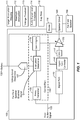
- FIG 1 is an illustration of an environment 100 for determining an amount of attenuation to apply to an input audio signal.
- the environment 100 may be implemented using a mobile station 800 and/or a computing device 900 described with respect to Figures 8 and 9 , respectively.
- the environment 100 includes a control path 150 that includes a delay generator 105, an attenuation determiner 110, and a gain engine 115.
- the environment 100 further includes a signal path 140, a battery 130, a voltage level determiner 107, an amplifier 170, a DAC (digital-to-analog converter) 147, a digital gain controller 145, a booster 116, a speaker driver 180, and a far-field speaker 190. More or fewer components may be supported.
- An input audio signal 120 may be received by the environment 100.
- the input audio signal 120 may be generated by a processor or other component of the mobile station associated with the environment 100.
- the input audio signal 120 may be a digital audio signal generated by the mobile station during audio or video playback, or as part of a telephonic conversation.
- the input audio signal 120 may pass through what is referred to herein as the signal path 140.
- the signal path 140 may represent a variety of functional and/or processing components that may act on the input audio signal 120 as part of one or more supported codecs.
- the components of the signal path 140 may include an up-sampler and a zero order hold.
- the signal path 140 may further include the DAC 147 and the digital gain controller 145. More or fewer components may also be included in the signal path 140.
- the input audio signal 120 may pass through an amplifier 170 (or optionally the digital gain controller 145 and/or the DAC 147) to a speaker driver 180.
- the speaker driver 180 may provide the processed audio signal as output to a far-field speaker 190.
- the amplifier 170 may utilize a voltage boost by the booster 116.
- the speaker driver 180 may receive its power from an additional 5 V boost instead of directly from the battery.
- the mobile station may not have enough available voltage to power other components of the mobile station (i.e., may brown out) or in some cases may reset when the far-field speaker is in use and outputting large signals.
- the environment 100 may include the control path 150 to prevent one or more of the adverse effects associated with the usage of the far-field speaker 190.
- the control path 150 may determine whether to apply attenuation to the input audio signal 120 (i.e., attenuate the input audio signal 120), and if so, how much attenuation to apply before the input audio signal 120 is provided to the far-field speaker 190.
- the attenuation may result in a temporary drop in the volume of the input audio signal 120, and therefore reduce the current drawn by the speaker driver 180.
- the reduced current may prevent the reset and/or brown out conditions described above.
- the control path 150 may include a delay generator 105.
- the delay generator 105 may add an amount of delay to the control path 150 that is equivalent to the overall delay of the signal path 140. As may be appreciated, the delay may be added to the control path 150 so that the determination whether to attenuate the input audio signal 120 may be made proximate to the input audio signal 120 exiting the signal path 140. Thus, the delay generator 105 may sync the input audio signal 120 in the control path 150 with the input audio signal 120 in the signal path 140.
- the amount of the delay added to the input audio signal 120 by the delay generator 105 may be dependent on a variety of implementation details, such as the type of codec and interpolation filters used by the signal path 140.
- the amount of delay added by the delay generator 105 may also be reduced to account for delay introduced by the other components of the control path 150 such as by the attenuation determiner 110 and the gain engine 115.
- the delay from the signal path 140 may be a measure of the time from when the input audio signal 120 enters the signal path 140 to the time the input audio signal 120 exits the signal path 140 (including the DAC 147 and/or the digital gain controller 145).
- the delay from the attenuation determiner 110 may be the delay associated with determining whether to apply attenuation to the input audio signal 120.
- the delay from the gain engine 115 may be the delay associated with applying the attenuation to the input audio signal 120, and may include any delay associated with configuring the amplifier 170.
- the attenuation determiner 110 may receive the input audio signal 120 after the delay has been applied from the delay generator 105, and may determine how much, if any, attenuation to apply to the input audio signal 120. In addition, if attenuation is already being applied to the input audio signal 120, the attenuation determiner 110 may determine if the applied attenuation may be adjusted or eliminated.
- the attenuation determiner 110 may receive a battery voltage level from the voltage level determiner 107, and may determine whether to attenuate the input audio signal 120 based on the received battery voltage level. In some implementations, the attenuation determiner 110 may determine to attenuate the input audio signal 120 if the battery voltage level is less than a voltage threshold 113. In some implementations, the voltage threshold 113 may be 3.6 volts. However, other voltage thresholds 113 may be supported and/or selected by a user or an administrator, for example.
- the attenuation determiner 110 may further determine a level of the input audio signal 120. In some implementations, the attenuation determiner 110 may determine the level of the input audio signal 120 based on one or more peak input audio signal 120 levels. The attenuation determiner 110 may determine peak input audio signal 120 levels for each block of the input audio signal 120. For example, 10 ms blocks may be used. The attenuation determiner 110 may forget previously determined peaks levels from blocks every 20 ms. The attenuation determiner 110 may then use a current maximum peak input audio signal 120 level from one of the blocks as the input audio signal 120 level.
- the attenuation determiner 110 may determine the level of the input audio signal 120 based on an average level of the input audio signal 120.
- the attenuation determiner 110 may determine the average level for each block of the input audio signal level 120. For example, the average may be computed by averaging the absolute levels within a block or it may be computed as root mean squared (RMS) value of the levels within a block.
- RMS root mean squared
- the attenuation determiner 110 may then average the determined levels for one or more of the blocks to smooth out the determined levels.
- the attenuation determiner 110 may then use a current average level as the input audio signal 120 level.
- the voltage level determiner 107 may comprise one or more of a variety of known analog-to-digital voltage converters. The voltage level determiner 107 may quickly determine the battery voltage level so that the attenuation determiner 110 may make the attenuation determination using the current conditions of the battery 130. In some implementations, the voltage level determiner 107 may determine the battery voltage level with 8 bits of accuracy, although other accuracy levels may also be supported.
- the voltage level determiner 107 may employ filtering techniques to smooth the determined battery voltage levels. For example, a first order infinite impulse response (IIR) filter with smoothing constant 'a' having a value of approximately 0.5 may be used. Other types of filters and smoothing constant values may also be used. As another example, a finite impulse response (FIR) filter, such as a 10 tap moving average filter, may also be used.
- IIR infinite impulse response
- FIR finite impulse response
- the attenuation determiner 110 may further determine whether to attenuate the input audio signal 120 based on a level of the input audio signal 120, as well as the voltage level of the battery 130.
- the attenuation determiner 110 may determine the level of the input audio signal 120 as described above, and may compare the level of the input audio signal 120 to an audio signal level threshold 114.
- the attenuation determiner 110 may then determine to attenuate the input audio signal 120 if the level of the input audio signal 120 is above the audio signal level threshold 114.
- the threshold 114 may be set by a user or an administrator, for example.
- the attenuation determiner 110 may determine whether to attenuate the input audio signal 120 only if the battery voltage level is below the voltage threshold 113, regardless of the level of the input audio signal 120. In these implementations, the attenuation determiner 110 may only determine the level of the input audio signal 120 if the battery voltage level is below the voltage threshold 113. In other implementations, the attenuation determiner 110 may determine whether to attenuate the input audio signal 120 only if the input audio signal level is above the audio signal level threshold 114, regardless of the battery voltage level. In these implementations, the attenuation determiner 110 may only determine the battery voltage level if the level of the input audio signal 120 is above the audio signal level threshold 114.
- the attenuation determiner 110 may receive a far-field speaker enabled signal 101, and may determine whether to attenuate the input audio signal 120 based on the signal 101.
- the far-field speaker enabled signal 101 may be received from a processor or component associated with the mobile station and may indicate whether or not the far-field speaker 190 has been enabled. Accordingly, if the far-field speaker 190 is not enabled, then the attenuation determiner 110 may not determine to attenuate the input audio signal 120. In such implementations, if the far-field speaker 190 is not enabled, then the attenuation determiner 110 may not determine either of the battery voltage level or the input audio signal level.
- the attenuation determiner 110 may determine a target amount of attenuation to apply to the input audio signal 120.
- the attenuation determiner 110 may determine the target attenuation to apply based on the battery voltage level of the battery 130 and a target attenuation mapping 111.
- the mapping 111 may comprise a table or other data structure that indicates the target attenuation to apply for a given battery voltage level.
- the target attenuation mapping 111 may comprise a factor or other value that may be multiplied by the battery voltage level (or otherwise applied to the battery voltage level) to determine the target attenuation.
- the input audio level 120 may be used to select the target attenuation mapping to use.
- the attenuation determiner 110 may further determine the target attenuation according to a maximum attenuation 112.
- the maximum attenuation 112 may be set by a user or an administrator, for example, and may be a maximum amount of attenuation that may be applied to the input audio signal 120. If the target attenuation determined by the attenuation determiner 110 using the target attenuation mapping is above the maximum attenuation 112, then the attenuation determiner 110 may set the target attenuation to the maximum attenuation 112.
- Figure 2 is a graph 200 illustrating example target attenuations determined by the attenuation determiner 110.
- the y-axis of the graph 200 shows target attenuation
- the x-axis of the graph 300 shows battery voltage level.
- the graph 200 shows three different target attenuation mappings 111a, 111b, and 111c.
- Each target attenuation mapping 111a-c is associated with a different attenuation rate, reflected by the slopes of lines of mappings 111a-c, respectively.
- the input audio signal 120 is attenuated by 1 db for every 0.1 V drop in battery voltage level.
- the input audio signal 120 is attenuated by 2 db for every 0.1 V drop in battery voltage level.
- the input audio signal 120 is attenuated by 6 db for every 0.1 V drop in battery voltage level.
- the input audio signal 120 is only attenuated when the voltage drops below the voltage threshold 113 of 3.6 volts. This voltage threshold 113 acts as a trip point.
- the target attenuation is never greater than the maximum attenuation 112 of -6 db.
- the input audio signal 120 is negatively attenuated to reduce the volume of the input audio signal 120, thus an attenuation of -12 db represents a greater amount of attenuation than -1 db, for example.
- the amount of attenuation to apply can be determined as: (trip point - battery voltage level) x slope (not to be exceeded by the maximum attenuation).
- the maximum attenuation 112 provides the attenuation determiner 110 with an upper limit of attenuation to apply.
- the value of the maximum attenuation 112 is programmable, in an implementation.
- the gain engine 115 receives the target attenuation from the attenuation determiner 110 and applies the target attenuation to the input audio signal 120. In some implementations the gain engine 115 may apply the target attenuation by configuring the amplifier 170. Alternatively, or additionally, the gain engine 115 may apply the target attenuation by writing new gain values into an audio power amplifier associated with a codec being implemented by the environment 100.
- the gain engine 115 may apply the target attenuation in the digital domain, prior to the amplifier 170 or the speaker driver 180.
- the gain engine 115 may configure the digital gain controller 145 to apply the gain digitally to the input audio signal 120, rather than the amplifier 170.
- the digital gain controller 145 may be implemented using a variety of well known techniques.
- the gain engine 115 may gradually apply the target attenuation to the input audio signal 120 over time.
- the rate at which the gain engine 115 may apply the target attenuation is known as a step rate 118, and may be set by a user or an administrator, for example.
- An example step rate 118 may be 10 ⁇ s/.5 db, meaning that the attenuation may be applied to the input audio signal 120 at a rate of 0.5 db every 10 ⁇ s until the target attenuation is reached.
- the step rate 118 used by the gain engine 115 may be the same whether or not a current attenuation is raised or lowered to reach the target attenuation. In other implementations, a different step rate 118 may be used depending on whether the attenuation is raised or lowered by the gain engine 115.
- the gain engine 115 takes the information from the attenuation determiner 110 and writes the new gain values into the codec's audio power amplifier or into the digital gain controller 145 to digital to analog conversion.
- the gain is not updated instantaneously, but by specific attack and release times. Both the attack and release times may be programmable values.
- the attack time refers to how quickly the gain should be stepped down from one target value to the next. For example, a typical value may be 10 ⁇ s/0.5 dB. This means that the gain should be lowered by 0.5 dB every 10 ⁇ s until the new target attenuation is reached.
- the release time refers to how quickly the gain should be stepped up from one target value to the next.
- a typical value may be 800 ms/0.5 dB. This means that the gain should be raised by 0.5 dB every 800 ms until the new target attenuation is reached.
- the attack time is applied when going lower in gain and the release time is applied when going higher in gain. It is noted that a new target attenuation could come in before the prior target attenuation has been reached. In such a case, the gain engine 115 may keep track of its current gain setting and its target.
- the attenuation determiner 110 may determine whether to attenuate the input audio signal 120 using what is referred to herein as a limiter based approach.
- the attenuation determiner 110 may determine if the input audio signal 120 level is greater than the audio signal level threshold 114, and if not, may determine not to attenuate the input audio signal 120 and may further determine to instruct the gain engine 115 to reduce the amount of attenuation currently applied to the input audio signal 120 (if any).
- the attenuation determiner 110 may calculate a limit threshold for the input audio signal 120 based on the voltage level of the battery 130 as determined by the voltage level determiner 107.
- the limit threshold may further be calculated based on the voltage threshold 113 (i.e., trip point) and the target attenuation mapping 111 (i.e., slope).
- the limit threshold may be determined by multiplying the difference between the battery voltage level and the trip point by the slope.
- the attenuation determiner 110 may then determine if the level of the input audio signal 120 (including any attenuation or gain currently applied) is greater than the calculated limit threshold. If the level is greater than the limit threshold, then the attenuation determiner 110 may instruct the gain engine 115 to increase the amount of attenuation applied to the input audio signal 120. Otherwise, the attenuation determiner 110 may instruct the gain engine 115 to decrease the amount of attenuation applied to the input audio signal 120.
- Figure 3 is an operational flow of an implementation of a method 300 for determining whether to attenuate an input audio signal.
- the method may be implemented by the attenuation determiner 110 of the control path 150.
- An input audio signal is received at 301.
- the input audio signal 120 may be received by the attenuation determiner 110 of the control path 150.
- the input audio signal 120 may be a digital audio signal and may be received from a processor or other component of a mobile station.
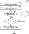
- Figure 4 is an operational flow of another implementation of a method 400 for determining whether to attenuate an input audio signal.
- the method 400 may be implemented by the attenuation determiner 110 of the control path 150.
- An input audio signal is received at 401.
- the input audio signal 120 may be received by the attenuation determiner 110 from the delay generator 105.
- a battery voltage level may be received at 403.
- the battery voltage level may be received by the attenuation determiner 110 from the voltage level determiner 107.
- the battery voltage level may be a measure of the available voltage of the battery 130 of a mobile station.
- the determination may be made by the attenuation determiner 110.
- the first threshold may be the voltage threshold 113, and may be set by a user or an administrator, for example. If the battery voltage level is above the first threshold, then there is no risk of a reset or brown out due to the audio signal and the method 400 may determine no attenuation is needed at 407. Otherwise, if the battery voltage is below the first threshold, then the method 400 may continue at 409.
- the second threshold may be the audio signal level threshold 114, and may also be set by a user or an administrator. If the input audio signal is below the second threshold, then there is similarly no risk of a system reset or brown out, and the method 400 may determine that no attenuation is needed at 407. Otherwise, processing may continue at 411 where a target attenuation is determined.
- a target attenuation is determined at 411.
- the target attenuation may be determined by the attenuation determiner 110 using the battery voltage level, target attenuation mapping 111, and a maximum attenuation 112, for example.
- the target attenuation may then be provided to the gain engine 115 where the target attenuation may be applied to the input audio signal 120.
- Figure 5 is an operational flow of an implementation of a method 500 for determining a target attenuation for an input audio signal.
- the method 500 may be implemented by the attenuation determiner 110.
- a mapping is received at 501.
- the mapping may be received by the attenuation determiner 110.
- the mapping may be the target attenuation mapping 111 and may comprise a mapping from battery voltage levels to target attenuations.
- the mapping may be a factor or other value that may be multiplied by the battery voltage level (or otherwise applied to the voltage level) to determine the target attenuation.
- a target attenuation is determined using the mapping and the battery voltage level at 503.
- the target attenuation may be determined by the attenuation determiner 110.
- the target attenuation mapping 111 is a value
- the value may be multiplied by the battery voltage level to determine the target attenuation.
- the determination may be made by the attenuation determiner 110 using the maximum attenuation 112.
- the maximum attenuation 112 may be set by a user or an administrator and may represent the maximum attenuation that may be applied to the input audio signal 120. If the target attenuation is less than the maximum attenuation 112, then the target attenuation may be returned at 507 to be applied to attenuate the signal. Otherwise, processing may continue at 509.
- the target attenuation may be set to the maximum attenuation at 509. Because the determined target attenuation was greater than the maximum attenuation 112, the attenuation determiner 110 may set the target attenuation to the maximum attenuation 110. After setting the target attenuation to the maximum attenuation 112, the method 500 may return the target attenuation at 507 to be applied to attenuate the signal.
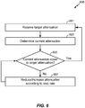
- Figure 6 is an operational flow of an implementation of a method 600 for adjusting an attenuation applied to an input audio signal.
- the method 600 may be implemented by the gain engine 115 of the control path 150.
- a target attenuation is received at 601.
- the target attenuation may have been determined by the attenuation determiner 110 and received by the gain engine 115.
- a current attenuation is determined at 603.
- the current attenuation may be determined by the gain engine 115 and may be the attenuation that is being applied to the input audio signal 120 by the amplifier 170 or somewhere in the digital signal path.
- the current attenuation is reduced or increased according to a step rate at 607.
- the current attenuation may be increased or reduced by the gain engine 115 through the amplifier 170 or the digital gain controller 145.
- the increase or reduction may be made according to the step rate 118 and may be set by a user or an administrator, for example. In some implementations, a separate step rate 118 may be used depending on whether the current attenuation is increased or decreased.
- the method 600 may return to 605 to determine if the current attenuation is equal to the target attenuation.
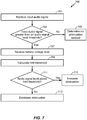
- Figure 7 is an operational flow of an implementation of a method 700 for determining whether to increase or decrease an amount of attenuation applied to an input audio signal.
- the method 700 is an example of the limiter based approach for adjusting attenuation.
- the method 700 may be implemented by the attenuation determiner 110 of the control path 150.
- An input audio signal is received at 701.
- the input audio signal 120 may be received by the attenuation determiner 110 from the delay generator 105.
- a battery voltage level is received at 707.
- the battery voltage level may be received by the attenuation determiner 110 from the voltage level determiner 107.
- the battery voltage level may be a measure of the available voltage of the battery 130 of a mobile station.
- a limit threshold is calculated at 709.
- the limit threshold may be calculated by the attenuation determiner 110 using the battery voltage level.
- the limit threshold may be calculated by the attenuation determiner 110 using the received battery voltage level, the target attenuation mapping 111, and the voltage threshold 113.
- determining (and grammatical variants thereof) is used in an extremely broad sense.
- the term “determining” encompasses a wide variety of actions and, therefore, “determining” can include calculating, computing, processing, deriving, investigating, looking up (e.g., looking up in a table, a database or another data structure), ascertaining and the like.
- determining can include receiving (e.g., receiving information), accessing (e.g., accessing data in a memory) and the like. Also, “determining” can include resolving, selecting, choosing, establishing and the like.
- any disclosure of an operation of an apparatus having a particular feature is also expressly intended to disclose a method having an analogous feature (and vice versa), and any disclosure of an operation of an apparatus according to a particular configuration is also expressly intended to disclose a method according to an analogous configuration (and vice versa).
- FIG. 8 shows a block diagram of a design of an example mobile station 800 in a wireless communication system.
- Mobile station 800 may be a cellular phone, a terminal, a handset, a PDA, a wireless modem, a cordless phone, etc.
- the wireless communication system may be a CDMA system, a GSM system, etc.
- Mobile station 800 is capable of providing bidirectional communication via a receive path and a transmit path.
- signals transmitted by base stations are received by an antenna 812 and provided to a receiver (RCVR) 814.
- Receiver 814 conditions and digitizes the received signal and provides samples to a digital section 820 for further processing.
- a transmitter (TMTR) 816 receives data to be transmitted from digital section 820, processes and conditions the data, and generates a modulated signal, which is transmitted via antenna 812 to the base stations.
- Receiver 814 and transmitter 816 may be part of a transceiver that may support CDMA, GSM, etc.
- Digital section 820 includes various processing, interface, and memory units such as, for example, a modem processor 822, a reduced instruction set computer/ digital signal processor (RISC/DSP) 824, a controller/processor 826, an internal memory 828, a generalized audio encoder 832, a generalized audio decoder 834, a graphics/display processor 836, and an external bus interface (EBI) 738.
- Modem processor 822 may perform processing for data transmission and reception, e.g., encoding, modulation, demodulation, and decoding.
- RISC/DSP 824 may perform general and specialized processing for wireless device 800.
- Controller/processor 826 may direct the operation of various processing and interface units within digital section 820.
- Internal memory 828 may store data and/or instructions for various units within digital section 820.
- Generalized audio encoder 832 may perform encoding for input signals from an audio source 842, a microphone 843, etc.
- Generalized audio decoder 834 may perform decoding for coded audio data and may provide output signals to a speaker/headset 844.
- Graphics/display processor 836 may perform processing for graphics, videos, images, and texts, which may be presented to a display unit 846.
- EBI 838 may facilitate transfer of data between digital section 820 and a main memory 848.
- Digital section 820 may be implemented with one or more processors, DSPs, microprocessors, RISCs, etc. Digital section 820 may also be fabricated on one or more application specific integrated circuits (ASICs) and/or some other type of integrated circuits (ICs).
- ASICs application specific integrated circuits
- ICs integrated circuits
- Figure 9 shows an exemplary computing environment in which example implementations and aspects may be implemented.
- the computing system environment is only one example of a suitable computing environment and is not intended to suggest any limitation as to the scope of use or functionality.
- Computer-executable instructions such as program modules, being executed by a computer may be used.
- program modules include routines, programs, objects, components, data structures, etc. that perform particular tasks or implement particular abstract data types.
- Distributed computing environments may be used where tasks are performed by remote processing devices that are linked through a communications network or other data transmission medium.
- program modules and other data may be located in both local and remote computer storage media including memory storage devices.
- an exemplary system for implementing aspects described herein includes a computing device, such as computing device 900.
- computing device 900 typically includes at least one processing unit 902 and memory 904.
- memory 904 may be volatile (such as random access memory (RAM)), non-volatile (such as read-only memory (ROM), flash memory, etc.), or some combination of the two.
- RAM random access memory
- ROM read-only memory
- flash memory etc.
- Computing device 900 may have additional features and/or functionality.
- computing device 900 may include additional storage (removable and/or non-removable) including, but not limited to, magnetic or optical disks or tape.
- additional storage is illustrated in Figure 9 by removable storage 908 and non-removable storage 910.
- Computing device 900 typically includes a variety of computer-readable media.
- Computer-readable media can be any available media that can be accessed by device 900 and include both volatile and non-volatile media, and removable and non-removable media.
- Computer storage media include volatile and non-volatile, and removable and non-removable media implemented in any method or technology for storage of information such as computer readable instructions, data structures, program modules or other data.
- Memory 904, removable storage 908, and non-removable storage 910 are all examples of computer storage media.
- Computer storage media include, but are not limited to, RAM, ROM, electrically erasable program read-only memory (EEPROM), flash memory or other memory technology, CD-ROM, digital versatile disks (DVD) or other optical storage, magnetic cassettes, magnetic tape, magnetic disk storage or other magnetic storage devices, or any other medium which can be used to store the desired information and which can be accessed by computing device 900. Any such computer storage media may be part of computing device 900.
- Computing device 900 may contain communications connection(s) 912 that allow the device to communicate with other devices.
- Computing device 900 may also have input device(s) 914 such as a keyboard, mouse, pen, voice input device, touch input device, etc.
- Output device(s) 916 such as a display, speakers, printer, etc. may also be included. All these devices are well known in the art and need not be discussed at length here.
- any device described herein may represent various types of devices, such as a wireless or wired phone, a cellular phone, a laptop computer, a wireless multimedia device, a wireless communication PC card, a PDA, an external or internal modem, a device that communicates through a wireless or wired channel, etc.
- a device may have various names, such as access terminal (AT), access unit, subscriber unit, mobile station, mobile device, mobile unit, mobile phone, mobile, remote station, remote terminal, remote unit, user device, user equipment, handheld device, non-mobile station, non-mobile device, endpoint, etc.
- Any device described herein may have a memory for storing instructions and data, as well as hardware, software, firmware, or combinations thereof.
- the attenuation techniques described herein may be implemented by various means. For example, these techniques may be implemented in hardware, firmware, software, or a combination thereof. Those of skill would further appreciate that the various illustrative logical blocks, modules, circuits, and algorithm steps described in connection with the disclosure herein may be implemented as electronic hardware, computer software, or combinations of both. To clearly illustrate this interchangeability of hardware and software, various illustrative components, blocks, modules, circuits, and steps have been described above generally in terms of their functionality. Whether such functionality is implemented as hardware or software depends upon the particular application and design constraints imposed on the overall system. Skilled artisans may implement the described functionality in varying ways for each particular application, but such implementation decisions should not be interpreted as causing a departure from the scope of the present disclosure.
- processing units used to perform the techniques may be implemented within one or more ASICs, DSPs, digital signal processing devices (DSPDs), programmable logic devices (PLDs), field programmable gate arrays (FPGAs), processors, controllers, micro-controllers, microprocessors, electronic devices, other electronic units designed to perform the functions described herein, a computer, or a combination thereof.
- ASICs application specific integrated circuits
- DSPs digital signal processing devices
- DSPDs digital signal processing devices
- PLDs programmable logic devices
- FPGAs field programmable gate arrays
- processors controllers, micro-controllers, microprocessors, electronic devices, other electronic units designed to perform the functions described herein, a computer, or a combination thereof.
- a general-purpose processor may be a microprocessor, but in the alternative, the processor may be any conventional processor, controller, microcontroller, or state machine.
- a processor may also be implemented as a combination of computing devices, e.g., a combination of a DSP and a microprocessor, a plurality of microprocessors, one or more microprocessors in conjunction with a DSP core, or any other such configuration.
- the techniques may be embodied as instructions on a computer-readable medium, such as random access RAM, ROM, non-volatile RAM, programmable ROM, EEPROM, flash memory, compact disc (CD), magnetic or optical data storage device, or the like.
- the instructions may be executable by one or more processors and may cause the processor(s) to perform certain aspects of the functionality described herein.
- Computer-readable media includes both computer storage media and communication media including any medium that facilitates transfer of a computer program from one place to another.
- a storage media may be any available media that can be accessed by a general purpose or special purpose computer.
- such computer-readable media can comprise RAM, ROM, EEPROM, CD-ROM or other optical disk storage, magnetic disk storage or other magnetic storage devices, or any other medium that can be used to carry or store desired program code means in the form of instructions or data structures and that can be accessed by a general-purpose or special-purpose computer, or a general-purpose or special-purpose processor.
- any connection is properly termed a computer-readable medium.
- the software is transmitted from a website, server, or other remote source using a coaxial cable, fiber optic cable, twisted pair, digital subscriber line (DSL), or wireless technologies such as infrared, radio, and microwave
- the coaxial cable, fiber optic cable, twisted pair, DSL, or wireless technologies such as infrared, radio, and microwave are included in the definition of medium.
- Disk and disc includes CD, laser disc, optical disc, digital versatile disc (DVD), floppy disk and blu-ray disc where disks usually reproduce data magnetically, while discs reproduce data optically with lasers. Combinations of the above should also be included within the scope of computer-readable media.
- a software module may reside in RAM memory, flash memory, ROM memory, EPROM memory, EEPROM memory, registers, hard disk, a removable disk, a CD-ROM, or any other form of storage medium known in the art.
- An exemplary storage medium is coupled to the processor such that the processor can read information from, and write information to, the storage medium.
- the storage medium may be integral to the processor.
- the processor and the storage medium may reside in an ASIC.
- the ASIC may reside in a user terminal.
- the processor and the storage medium may reside as discrete components in a user terminal
- exemplary implementations may refer to utilizing aspects of the presently disclosed subject matter in the context of one or more stand-alone computer systems, the subject matter is not so limited, but rather may be implemented in connection with any computing environment, such as a network or distributed computing environment. Still further, aspects of the presently disclosed subject matter may be implemented in or across a plurality of processing chips or devices, and storage may similarly be effected across a plurality of devices. Such devices might include PCs, network servers, and handheld devices, for example.
Landscapes
- Engineering & Computer Science (AREA)
- Theoretical Computer Science (AREA)
- Physics & Mathematics (AREA)
- General Engineering & Computer Science (AREA)
- General Physics & Mathematics (AREA)
- Signal Processing (AREA)
- Human Computer Interaction (AREA)
- Computer Networks & Wireless Communication (AREA)
- Circuit For Audible Band Transducer (AREA)
- Telephone Function (AREA)
Claims (15)
- Verfahren zum Dämpfen von Audiosignalen in einem Mobiltelefon, das Folgendes beinhaltet:Bestimmen (701) eines Batteriespannungspegels einer Batterie des Mobiltelefons;Bestimmen eines Audiosignalpegels eines Audiosignals;Vergleichen (711) des Audiosignalpegels mit einer Schwelle;Feststellen (705, 715) auf der Basis des Batteriespannungspegels und auf der Basis des Vergleichs, ob das Audiosignal gedämpft werden soll; undAuswählen einer Dämpfung zur Anwendung auf das Audiosignal aus mehreren unterschiedlichen Dämpfungsraten auf der Basis des bestimmten Batteriespannungspegels, wobei eine Änderung des Audiosignalpegels mit einer Änderung des Batteriespannungspegels assoziiert ist;gekennzeichnet durch Bestimmen einer Verzögerung zum Hinzufügen zu einem Steuerpfad (150), so dass ein mit dem Steuerpfad (150) assoziierter Verzögerungsbetrag mit einer mit einem Signalpfad (140) assoziierten Verzögerung äquivalent ist.
- Verfahren nach Anspruch 1, wobei die Schwelle eine zweite Schwelle ist und wobei das Dämpfen des Audiosignals auf der Basis des Batteriespannungspegels und des Audiosignalpegels das Dämpfen des Audiosignals nur dann beinhaltet, wenn der Batteriespannungspegel unter einer ersten Schwelle ist und wenn der Audiosignalpegel über der zweiten Schwelle ist, und das ferner vorzugsweise das Feststellen beinhaltet, ob das Audiosignal zu dämpfen ist, auf der Basis davon, ob ein Fernfeldlautsprecher-Enable-Signal empfangen wurde.
- Verfahren nach Anspruch 2, wobei das Bestimmen des Batteriespannungspegels nur dann erfolgt, wenn der Audiosignalpegel über der zweiten Schwelle liegt, und wobei vorzugsweise das Bestimmen des Audiosignalpegels nur dann erfolgt, wenn der Batteriespannungspegel unter der ersten Schwelle liegt, und wobei insbesondere das Audiosignal nicht gedämpft wird, wenn der Batteriespannungspegel über der ersten Schwelle liegt oder wenn der Audiosignalpegel unter der zweiten Schwelle liegt.
- Verfahren nach Anspruch 1, das ferner das Bestimmen einer Zieldämpfung des Audiosignals auf der Basis des Batteriespannungspegels, eines Mappings von Batteriespannungspegeln auf Zieldämpfungen und einer maximalen Dämpfung beinhaltet, und das vorzugsweise ferner das Bestimmen einer Spannungserhöhung auf der Basis der Zieldämpfung und einer aktuellen Dämpfung beinhaltet und insbesondere ferner das Bestimmen der Dämpfungserhöhung auf der Basis einer Stufenrate beinhaltet.
- Verfahren nach Anspruch 1, das ferner das Empfangen des Audiosignals an dem Mobiltelefon beinhaltet, und wobei vorzugsweise das Dämpfen des Audiosignals einen partiellen Ausfall der Batteriespannung und ein Rückstellen des Mobiltelefons verhindert, und wobei insbesondere das Bestimmen des Batteriespannungspegels nur dann erfolgt, wenn ein Fernfeldlautsprecher im Gebrauch ist.
- Verfahren nach Anspruch 1, wobei die Schwelle eine Grenzschwelle ist und wobei das Dämpfen des Audiosignals auf der Basis des Batteriespannungspegels und des Audiosignalpegels Folgendes beinhaltet:Berechnen der Grenzschwelle auf der Basis des Batteriespannungspegels;Bestimmen einer Dämpfungszunahme, wenn der Audiosignalpegel über der Grenzschwelle liegt; undBestimmen einer Dämpfungsabnahme, wenn der Audiosignalpegel nicht über der Grenzschwelle liegt.
- Verfahren nach Anspruch 6, wobei das Berechnen der Grenzschwelle ferner das Berechnen der Grenzschwelle auf der Basis des Batteriespannungspegels, eines Mappings von Batteriespannungspegeln auf Zieldämpfungen und eines Schwellen-Batteriespannungspegels beinhaltet.
- Verfahren nach Anspruch 1, das ferner den Schritt des Bestimmens einer Grenzschwelle für das Eingangsaudiosignal auf der Basis des Batteriespannungspegels und vorzugsweise des Bestimmens der Grenzschwelle auf der Basis der Batteriespannungsschwelle und der gewählten Dämpfung beinhaltet und das insbesondere ferner den Schritt des Bestimmens der Frequenz in der Zeit, mit der die Dämpfung auf den Audiosignalpegel angewendet wird, und ferner vorzugsweise des Erzeugens einer Verzögerung für das Audiosignal auf der Basis von in dem Signalpfad benutzten Interpolationsfiltern und dem Typ von Encoder oder Decoder beinhaltet.
- Vorrichtung zum Dämpfen von Audiosignalen in einem Mobiltelefon, die Folgendes umfasst:Mittel zum Bestimmen (107) eines Batteriespannungspegels einer Batterie des Mobiltelefons;Mittel zum Bestimmen (882) eines Audiosignalpegels eines Audiosignals;Mittel zum Vergleichen (822) des Audiosignalpegels mit einer Schwelle;Feststellmittel (110) zum Feststellen auf der Basis des Batteriespannungspegels und auf der Basis des Vergleichs, ob das Audiosignal gedämpft werden soll; undAuswahlmittel (110) zum Auswählen, aus mehreren unterschiedlichen Dämpfungsraten, einer Dämpfung zur Anwendung auf das Audiosignal auf der Basis des bestimmten Batteriespannungspegels, wobei eine Änderung des Audiosignalpegels mit einer Änderung des Batteriespannungspegels assoziiert ist;dadurch gekennzeichnet, dass sie ferner Folgendes umfasst:
einen Verzögerungsgenerator (105) zum Bestimmen einer Verzögerung zum Hinzufügen zu einem Steuerpfad (150), so dass ein mit dem Steuerpfad (150) assoziierter Verzögerungsbetrag mit einer mit einem Signalpfad (140) assoziierten Verzögerung äquivalent ist. - Vorrichtung nach Anspruch 9, wobei die Schwelle eine zweite Schwelle ist und wobei das Mittel zum Dämpfen des Audiosignals auf der Basis des Batteriespannungspegels und des Audiosignalpegels das Audiosignal nur dann dämpft, wenn der Batteriespannungspegel unter einer ersten Schwelle liegt und wenn der Audiosignalpegel über der zweiten Schwelle liegt, und die ferner vorzugsweise Mittel zum Bestimmen einer Zieldämpfung des Audiosignals auf der Basis des Batteriespannungspegels, eines Mappings von Batteriespannungspegeln auf Zieldämpfungen und einer maximalen Dämpfung umfasst.
- Vorrichtung nach Anspruch 10, wobei das Mittel zum Bestimmen des Batteriespannungspegels den Batteriespannungspegel nur dann bestimmt, wenn der Audiosignalpegel über der zweiten Schwelle liegt, und wobei vorzugsweise das Mittel zum Bestimmen des Audiosignalpegels den Audiosignalpegel nur dann bestimmt, wenn der Batteriespannungspegel unter der ersten Schwelle liegt, und wobei insbesondere das Mittel zum Dämpfen des Audiosignals das Audiosignal nur dann dämpft, wenn der Batteriespannungspegel über der ersten Schwelle liegt oder wenn der Audiosignalpegel unter der zweiten Schwelle liegt.
- Vorrichtung nach Anspruch 11, die ferner Mittel zum Bestimmen einer Dämpfungszunahme auf der Basis der Zieldämpfung und einer aktuellen Dämpfung umfasst, und wobei vorzugsweise das Mittel zum Bestimmen der Dämpfungszunahme die Dämpfungszunahme auf der Basis einer Schrittrate bestimmt.
- Vorrichtung nach Anspruch 9, die ferner Mittel zum Empfangen des Audiosignals am Mobiltelefon umfasst, und wobei vorzugsweise das Mittel zum Dämpfen des Audiosignals einen partiellen Ausfall der Batteriespannung oder eine Rückstellung des Mobiltelefons verhindert, und wobei ferner vorzugsweise das Mittel zum Bestimmen des Batteriespannungspegels die Batteriespannung nur dann bestimmt, wenn ein Fernfeldlautsprecher im Gebrauch ist, und wobei insbesondere die Schwelle eine Grenzschwelle ist, und wobei das Mittel zum Dämpfen des Audiosignals auf der Basis des Batteriespannungspegels und des Audiosignalpegels Folgendes umfasst:Mittel zum Berechnen der Grenzschwelle auf der Basis des Batteriespannungspegels;Mittel zum Bestimmen einer Dämpfungszunahme, wenn der Audiosignalpegel über der Grenzschwelle liegt; undMittel zum Bestimmen einer Dämpfungsabnahme, wenn der Audiosignalpegel nicht über der Grenzschwelle liegt.
- Vorrichtung nach Anspruch 13, wobei das Mittel zum Berechnen der Grenzschwelle die Grenzschwelle auf der Basis des Batteriespannungspegels, eines Mappings von Batteriespannungspegeln auf Zieldämpfungen und eines Schwellen-Batteriespannungspegels berechnet.
- Computerlesbares Medium, das Befehle umfasst, die bewirken, dass ein Computer das Verfahren nach einem der Ansprüche 1 bis 8 ausführt.
Applications Claiming Priority (3)
| Application Number | Priority Date | Filing Date | Title |
|---|---|---|---|
| US201161431409P | 2011-01-10 | 2011-01-10 | |
| US13/206,372 US9119159B2 (en) | 2011-01-10 | 2011-08-09 | Battery power monitoring and audio signal attenuation |
| PCT/US2012/020673 WO2012096898A1 (en) | 2011-01-10 | 2012-01-09 | Battery power monitoring and audio signal attenuation |
Publications (2)
| Publication Number | Publication Date |
|---|---|
| EP2664196A1 EP2664196A1 (de) | 2013-11-20 |
| EP2664196B1 true EP2664196B1 (de) | 2019-05-01 |
Family
ID=46455267
Family Applications (1)
| Application Number | Title | Priority Date | Filing Date |
|---|---|---|---|
| EP12701790.3A Active EP2664196B1 (de) | 2011-01-10 | 2012-01-09 | Batterieleistungsüberwachung und audiosignaldämpfung |
Country Status (6)
| Country | Link |
|---|---|
| US (1) | US9119159B2 (de) |
| EP (1) | EP2664196B1 (de) |
| JP (2) | JP2014509470A (de) |
| KR (1) | KR101547412B1 (de) |
| CN (1) | CN103283284B (de) |
| WO (1) | WO2012096898A1 (de) |
Families Citing this family (52)
| Publication number | Priority date | Publication date | Assignee | Title |
|---|---|---|---|---|
| US8258872B1 (en) | 2007-06-11 | 2012-09-04 | Sonos, Inc. | Multi-tier power supply for audio amplifiers |
| US9712127B2 (en) * | 2012-01-11 | 2017-07-18 | Richard Aylward | Intelligent method and apparatus for spectral expansion of an input signal |
| US9661579B1 (en) * | 2013-05-03 | 2017-05-23 | Marvell International Ltd. | Per-tone power control in OFDM |
| US10187025B1 (en) * | 2013-06-13 | 2019-01-22 | Cirrus Logic, Inc. | Systems and methods for predictively preventing a brownout condition in a personal audio device |
| US9831843B1 (en) * | 2013-09-05 | 2017-11-28 | Cirrus Logic, Inc. | Opportunistic playback state changes for audio devices |
| US9391576B1 (en) | 2013-09-05 | 2016-07-12 | Cirrus Logic, Inc. | Enhancement of dynamic range of audio signal path |
| CN103744505B (zh) * | 2014-01-20 | 2017-07-25 | 联想(北京)有限公司 | 信息处理方法及电子设备 |
| US9525940B1 (en) | 2014-03-05 | 2016-12-20 | Cirrus Logic, Inc. | Multi-path analog front end and analog-to-digital converter for a signal processing system |
| US9774342B1 (en) | 2014-03-05 | 2017-09-26 | Cirrus Logic, Inc. | Multi-path analog front end and analog-to-digital converter for a signal processing system |
| US9306588B2 (en) | 2014-04-14 | 2016-04-05 | Cirrus Logic, Inc. | Switchable secondary playback path |
| US10785568B2 (en) | 2014-06-26 | 2020-09-22 | Cirrus Logic, Inc. | Reducing audio artifacts in a system for enhancing dynamic range of audio signal path |
| US9337795B2 (en) | 2014-09-09 | 2016-05-10 | Cirrus Logic, Inc. | Systems and methods for gain calibration of an audio signal path |
| US9596537B2 (en) | 2014-09-11 | 2017-03-14 | Cirrus Logic, Inc. | Systems and methods for reduction of audio artifacts in an audio system with dynamic range enhancement |
| US9503027B2 (en) | 2014-10-27 | 2016-11-22 | Cirrus Logic, Inc. | Systems and methods for dynamic range enhancement using an open-loop modulator in parallel with a closed-loop modulator |
| US9584911B2 (en) | 2015-03-27 | 2017-02-28 | Cirrus Logic, Inc. | Multichip dynamic range enhancement (DRE) audio processing methods and apparatuses |
| EP3089364B1 (de) | 2015-05-01 | 2019-01-16 | Nxp B.V. | Verstärkungsfunktionssteuerung |
| US9959856B2 (en) | 2015-06-15 | 2018-05-01 | Cirrus Logic, Inc. | Systems and methods for reducing artifacts and improving performance of a multi-path analog-to-digital converter |
| KR102398712B1 (ko) | 2015-08-07 | 2022-05-17 | 시러스 로직 인터내셔널 세미컨덕터 리미티드 | 공급 입력 전류를 제한하기 위한 피크 인덕터 전류의 조정 |
| WO2017039429A1 (en) * | 2015-08-28 | 2017-03-09 | Motorola Solutions, Inc. | Attenuator circuit for an electronic device having a battery and method for controlling the electronic device |
| CN105553434A (zh) * | 2015-10-28 | 2016-05-04 | 东莞酷派软件技术有限公司 | 智能终端的音频控制方法、系统及智能终端 |
| US10021485B2 (en) * | 2015-11-17 | 2018-07-10 | Cirrus Logic, Inc. | Prevention of signal clipping due to decrease in amplifier supply voltage |
| EP3171614B1 (de) | 2015-11-23 | 2020-11-04 | Goodix Technology (HK) Company Limited | Steuerung für ein audiosystem |
| KR102437156B1 (ko) * | 2015-11-24 | 2022-08-26 | 삼성전자주식회사 | 전자 장치의 상태에 따른 음성 신호 처리 방법 및 그 전자 장치 |
| US9955254B2 (en) | 2015-11-25 | 2018-04-24 | Cirrus Logic, Inc. | Systems and methods for preventing distortion due to supply-based modulation index changes in an audio playback system |
| US9543975B1 (en) | 2015-12-29 | 2017-01-10 | Cirrus Logic, Inc. | Multi-path analog front end and analog-to-digital converter for a signal processing system with low-pass filter between paths |
| US9880802B2 (en) | 2016-01-21 | 2018-01-30 | Cirrus Logic, Inc. | Systems and methods for reducing audio artifacts from switching between paths of a multi-path signal processing system |
| US10212514B2 (en) * | 2016-06-10 | 2019-02-19 | Cirrus Logic, Inc. | Method for limiting amplifier input current to avoid low voltage conditions |
| US10231050B2 (en) * | 2016-06-10 | 2019-03-12 | Cirrus Logic, Inc. | Method for limiting amplifier input current to avoid low voltage conditions |
| GB2551621A (en) * | 2016-06-10 | 2017-12-27 | Cirrus Logic Int Semiconductor Ltd | Method for limiting amplifier input current to avoid low voltage conditions |
| US9998826B2 (en) | 2016-06-28 | 2018-06-12 | Cirrus Logic, Inc. | Optimization of performance and power in audio system |
| US10123114B2 (en) * | 2016-07-09 | 2018-11-06 | Texas Instruments Incorporated | Brownout response |
| US10545561B2 (en) | 2016-08-10 | 2020-01-28 | Cirrus Logic, Inc. | Multi-path digitation based on input signal fidelity and output requirements |
| US10263630B2 (en) | 2016-08-11 | 2019-04-16 | Cirrus Logic, Inc. | Multi-path analog front end with adaptive path |
| US9813814B1 (en) | 2016-08-23 | 2017-11-07 | Cirrus Logic, Inc. | Enhancing dynamic range based on spectral content of signal |
| US9762255B1 (en) | 2016-09-19 | 2017-09-12 | Cirrus Logic, Inc. | Reconfiguring paths in a multiple path analog-to-digital converter |
| US9780800B1 (en) | 2016-09-19 | 2017-10-03 | Cirrus Logic, Inc. | Matching paths in a multiple path analog-to-digital converter |
| US9929703B1 (en) | 2016-09-27 | 2018-03-27 | Cirrus Logic, Inc. | Amplifier with configurable final output stage |
| US9967665B2 (en) | 2016-10-05 | 2018-05-08 | Cirrus Logic, Inc. | Adaptation of dynamic range enhancement based on noise floor of signal |
| CN106534411A (zh) * | 2016-11-09 | 2017-03-22 | Tcl通讯(宁波)有限公司 | 一种音量助推的驱动装置及移动终端 |
| CN110178382B (zh) * | 2017-01-20 | 2022-04-26 | 索尼公司 | 音频信号再现设备和控制方法 |
| CN106847249B (zh) * | 2017-01-25 | 2020-10-27 | 得理电子(上海)有限公司 | 一种发音处理方法及系统 |
| US10321230B2 (en) | 2017-04-07 | 2019-06-11 | Cirrus Logic, Inc. | Switching in an audio system with multiple playback paths |
| US10008992B1 (en) | 2017-04-14 | 2018-06-26 | Cirrus Logic, Inc. | Switching in amplifier with configurable final output stage |
| US9917557B1 (en) | 2017-04-17 | 2018-03-13 | Cirrus Logic, Inc. | Calibration for amplifier with configurable final output stage |
| US10469044B1 (en) * | 2017-12-21 | 2019-11-05 | Apple Inc. | Power mitigation for loudspeaker amplifiers |
| CN108307270A (zh) * | 2018-01-10 | 2018-07-20 | 海能达通信股份有限公司 | 一种功率放大控制电路、移动终端和对讲机 |
| GB202013376D0 (en) * | 2018-03-12 | 2020-10-07 | Cirrus Logic Int Semiconductor Ltd | Method for limiting amplifier input current to avoid low voltage conditions |
| US11689655B2 (en) * | 2018-10-15 | 2023-06-27 | Huawei Technologies Co., Ltd. | Method for adjusting parameter of audio service and terminal |
| TWI783210B (zh) * | 2020-02-06 | 2022-11-11 | 瑞昱半導體股份有限公司 | 音訊編解碼電路 |
| CN115695640B (zh) * | 2021-07-28 | 2024-10-18 | 华为技术有限公司 | 一种防关机保护方法及电子设备 |
| CN115527518B (zh) * | 2022-09-19 | 2026-04-03 | 轻谈(深圳)科技有限责任公司 | 基于通信网络的音频多轨合成方法、视频拍摄设备及系统 |
| DE102023001676A1 (de) * | 2023-04-26 | 2024-10-31 | Pan Acoustics Gmbh | Aktive Schallwandler-Vorrichtung |
Family Cites Families (18)
| Publication number | Priority date | Publication date | Assignee | Title |
|---|---|---|---|---|
| JP3295443B2 (ja) | 1991-10-09 | 2002-06-24 | パイオニア株式会社 | オーディオ装置における信号処理回路 |
| US6108426A (en) * | 1996-08-26 | 2000-08-22 | Compaq Computer Corporation | Audio power management |
| JP3722055B2 (ja) * | 2001-11-30 | 2005-11-30 | 日本電気株式会社 | 携帯端末装置 |
| US7110559B2 (en) | 2003-11-06 | 2006-09-19 | Motorola, Inc. | System and method for controlling audio output |
| KR100790068B1 (ko) | 2004-11-19 | 2007-12-31 | 삼성전자주식회사 | 디지털 멀티미디어 방송 수신 단말기의 파워 제어 장치 및 방법 |
| JP4876434B2 (ja) | 2005-04-28 | 2012-02-15 | カシオ計算機株式会社 | 音声出力制御装置および音声出力制御プログラム |
| US7945297B2 (en) | 2005-09-30 | 2011-05-17 | Atmel Corporation | Headsets and headset power management |
| US8036402B2 (en) * | 2005-12-15 | 2011-10-11 | Harman International Industries, Incorporated | Distortion compensation |
| US7848527B2 (en) * | 2006-02-27 | 2010-12-07 | Apple Inc. | Dynamic power management in a portable media delivery system |
| US8135443B2 (en) | 2006-08-31 | 2012-03-13 | Qualcomm Incorporated | Portable device with priority based power savings control and method thereof |
| US20080307240A1 (en) | 2007-06-08 | 2008-12-11 | Texas Instruments Incorporated | Power management electronic circuits, systems, and methods and processes of manufacture |
| EP2197105A1 (de) * | 2007-09-27 | 2010-06-16 | Yamaha Corporation | Elektronische vorrichtung |
| JP5298492B2 (ja) | 2007-10-05 | 2013-09-25 | ヤマハ株式会社 | 電子機器 |
| JP5125462B2 (ja) | 2007-12-06 | 2013-01-23 | ヤマハ株式会社 | 電子機器および音声再生装置 |
| US8775839B2 (en) | 2008-02-08 | 2014-07-08 | Texas Instruments Incorporated | Global hardware supervised power transition management circuits, processes and systems |
| US8855459B2 (en) | 2008-06-17 | 2014-10-07 | Apple Inc. | Method and apparatus for prolonging battery life of a media player |
| JP4998406B2 (ja) | 2008-08-11 | 2012-08-15 | 株式会社Jvcケンウッド | マルチチャンネルパワーアンプ及びマルチチャンネルオーディオ装置 |
| US8306238B2 (en) | 2009-06-17 | 2012-11-06 | Sony Ericsson Mobile Communications Ab | Method and circuit for controlling an output of an audio signal of a battery-powered device |
-
2011
- 2011-08-09 US US13/206,372 patent/US9119159B2/en active Active
-
2012
- 2012-01-09 CN CN201280004287.4A patent/CN103283284B/zh active Active
- 2012-01-09 EP EP12701790.3A patent/EP2664196B1/de active Active
- 2012-01-09 WO PCT/US2012/020673 patent/WO2012096898A1/en not_active Ceased
- 2012-01-09 JP JP2013549482A patent/JP2014509470A/ja active Pending
- 2012-01-09 KR KR1020137020987A patent/KR101547412B1/ko active Active
-
2015
- 2015-07-21 JP JP2015144272A patent/JP5996738B2/ja active Active
Non-Patent Citations (1)
| Title |
|---|
| None * |
Also Published As
| Publication number | Publication date |
|---|---|
| KR20130114718A (ko) | 2013-10-17 |
| US20120177226A1 (en) | 2012-07-12 |
| JP2014509470A (ja) | 2014-04-17 |
| EP2664196A1 (de) | 2013-11-20 |
| KR101547412B1 (ko) | 2015-08-25 |
| US9119159B2 (en) | 2015-08-25 |
| WO2012096898A1 (en) | 2012-07-19 |
| JP5996738B2 (ja) | 2016-09-21 |
| CN103283284A (zh) | 2013-09-04 |
| CN103283284B (zh) | 2017-03-08 |
| JP2015233308A (ja) | 2015-12-24 |
Similar Documents
| Publication | Publication Date | Title |
|---|---|---|
| US9119159B2 (en) | Battery power monitoring and audio signal attenuation | |
| US9299333B2 (en) | System for adaptive audio signal shaping for improved playback in a noisy environment | |
| EP3127114B1 (de) | Situationsabhängige vorübergehende unterdrückung | |
| CN104410379B (zh) | 一种音量调节方法 | |
| EP1796265B1 (de) | Tragbares Audiogerät mit automatischer Steuerung der Audiolautstärkenparameter zum Schutz des Gehörs | |
| JP3273599B2 (ja) | 音声符号化レート選択器と音声符号化装置 | |
| JP5598552B2 (ja) | 音声制御装置、音声制御方法、音声制御プログラム及び携帯端末装置 | |
| US9601128B2 (en) | Communication apparatus and voice processing method therefor | |
| WO2009097417A1 (en) | Improving sound quality by intelligently selecting between signals from a plurality of microphones | |
| EP2664161A1 (de) | Lautstärkemaximierung mit gesteuerter lautsprecherauslenkung | |
| US20160360331A1 (en) | Method and system for monitoring speaker temperature for speaker protection | |
| CN104363510B (zh) | 一种播放终端 | |
| CN111010739B (zh) | 物理资源块配置方法、装置、5g基站和可读存储介质 | |
| EP2449754A1 (de) | Vorrichtung, verfahren und computerprogramm zur steuerung eines akustischen signals | |
| EP3416357A1 (de) | Verfahren, vorrichtung und system zur verwaltung von audioparametern eines endgeräts | |
| TWI545891B (zh) | 防止在擴音器中電氣和機械飽和之波形整型系統 | |
| EP4029144B1 (de) | Dynamikbereichskompression mit reduzierten artefakten | |
| US20140114654A1 (en) | Method and system for peak limiting of speech signals for delay sensitive voice communication | |
| KR101644314B1 (ko) | 휴대용단말기에서 음원 재생시 음량제어 방법 및 장치 | |
| KR100726479B1 (ko) | 소정의 소음 측정 센서를 이용하여 통신 단말기의 사운드크기를 제어하는 방법 및 상기 방법을 채용한 통신 단말기 | |
| KR100561774B1 (ko) | 벨소리를 이용한 음량 자동 조절방법 | |
| WO2006055354A2 (en) | Adaptive time-based noise suppression | |
| CN109660655A (zh) | 音量调节方法、装置、终端及计算机可读介质 | |
| CN105828231A (zh) | 一种耳机音量控制方法、装置和终端设备 |
Legal Events
| Date | Code | Title | Description |
|---|---|---|---|
| PUAI | Public reference made under article 153(3) epc to a published international application that has entered the european phase |
Free format text: ORIGINAL CODE: 0009012 |
|
| 17P | Request for examination filed |
Effective date: 20130620 |
|
| AK | Designated contracting states |
Kind code of ref document: A1 Designated state(s): AL AT BE BG CH CY CZ DE DK EE ES FI FR GB GR HR HU IE IS IT LI LT LU LV MC MK MT NL NO PL PT RO RS SE SI SK SM TR |
|
| DAX | Request for extension of the european patent (deleted) | ||
| STAA | Information on the status of an ep patent application or granted ep patent |
Free format text: STATUS: EXAMINATION IS IN PROGRESS |
|
| 17Q | First examination report despatched |
Effective date: 20180419 |
|
| GRAP | Despatch of communication of intention to grant a patent |
Free format text: ORIGINAL CODE: EPIDOSNIGR1 |
|
| STAA | Information on the status of an ep patent application or granted ep patent |
Free format text: STATUS: GRANT OF PATENT IS INTENDED |
|
| RIC1 | Information provided on ipc code assigned before grant |
Ipc: H04W 52/02 20090101AFI20181012BHEP Ipc: H04M 1/60 20060101ALI20181012BHEP Ipc: H03G 3/00 20060101ALN20181012BHEP Ipc: G06F 1/32 20060101ALI20181012BHEP |
|
| INTG | Intention to grant announced |
Effective date: 20181120 |
|
| GRAS | Grant fee paid |
Free format text: ORIGINAL CODE: EPIDOSNIGR3 |
|
| GRAA | (expected) grant |
Free format text: ORIGINAL CODE: 0009210 |
|
| STAA | Information on the status of an ep patent application or granted ep patent |
Free format text: STATUS: THE PATENT HAS BEEN GRANTED |
|
| AK | Designated contracting states |
Kind code of ref document: B1 Designated state(s): AL AT BE BG CH CY CZ DE DK EE ES FI FR GB GR HR HU IE IS IT LI LT LU LV MC MK MT NL NO PL PT RO RS SE SI SK SM TR |
|
| REG | Reference to a national code |
Ref country code: GB Ref legal event code: FG4D |
|
| REG | Reference to a national code |
Ref country code: CH Ref legal event code: EP Ref country code: AT Ref legal event code: REF Ref document number: 1128616 Country of ref document: AT Kind code of ref document: T Effective date: 20190515 |
|
| REG | Reference to a national code |
Ref country code: DE Ref legal event code: R096 Ref document number: 602012059560 Country of ref document: DE |
|
| REG | Reference to a national code |
Ref country code: IE Ref legal event code: FG4D |
|
| REG | Reference to a national code |
Ref country code: NL Ref legal event code: MP Effective date: 20190501 |
|
| REG | Reference to a national code |
Ref country code: LT Ref legal event code: MG4D |
|
| PG25 | Lapsed in a contracting state [announced via postgrant information from national office to epo] |
Ref country code: SE Free format text: LAPSE BECAUSE OF FAILURE TO SUBMIT A TRANSLATION OF THE DESCRIPTION OR TO PAY THE FEE WITHIN THE PRESCRIBED TIME-LIMIT Effective date: 20190501 Ref country code: HR Free format text: LAPSE BECAUSE OF FAILURE TO SUBMIT A TRANSLATION OF THE DESCRIPTION OR TO PAY THE FEE WITHIN THE PRESCRIBED TIME-LIMIT Effective date: 20190501 Ref country code: AL Free format text: LAPSE BECAUSE OF FAILURE TO SUBMIT A TRANSLATION OF THE DESCRIPTION OR TO PAY THE FEE WITHIN THE PRESCRIBED TIME-LIMIT Effective date: 20190501 Ref country code: PT Free format text: LAPSE BECAUSE OF FAILURE TO SUBMIT A TRANSLATION OF THE DESCRIPTION OR TO PAY THE FEE WITHIN THE PRESCRIBED TIME-LIMIT Effective date: 20190901 Ref country code: FI Free format text: LAPSE BECAUSE OF FAILURE TO SUBMIT A TRANSLATION OF THE DESCRIPTION OR TO PAY THE FEE WITHIN THE PRESCRIBED TIME-LIMIT Effective date: 20190501 Ref country code: NO Free format text: LAPSE BECAUSE OF FAILURE TO SUBMIT A TRANSLATION OF THE DESCRIPTION OR TO PAY THE FEE WITHIN THE PRESCRIBED TIME-LIMIT Effective date: 20190801 Ref country code: ES Free format text: LAPSE BECAUSE OF FAILURE TO SUBMIT A TRANSLATION OF THE DESCRIPTION OR TO PAY THE FEE WITHIN THE PRESCRIBED TIME-LIMIT Effective date: 20190501 Ref country code: NL Free format text: LAPSE BECAUSE OF FAILURE TO SUBMIT A TRANSLATION OF THE DESCRIPTION OR TO PAY THE FEE WITHIN THE PRESCRIBED TIME-LIMIT Effective date: 20190501 Ref country code: LT Free format text: LAPSE BECAUSE OF FAILURE TO SUBMIT A TRANSLATION OF THE DESCRIPTION OR TO PAY THE FEE WITHIN THE PRESCRIBED TIME-LIMIT Effective date: 20190501 |
|
| PG25 | Lapsed in a contracting state [announced via postgrant information from national office to epo] |
Ref country code: RS Free format text: LAPSE BECAUSE OF FAILURE TO SUBMIT A TRANSLATION OF THE DESCRIPTION OR TO PAY THE FEE WITHIN THE PRESCRIBED TIME-LIMIT Effective date: 20190501 Ref country code: BG Free format text: LAPSE BECAUSE OF FAILURE TO SUBMIT A TRANSLATION OF THE DESCRIPTION OR TO PAY THE FEE WITHIN THE PRESCRIBED TIME-LIMIT Effective date: 20190801 Ref country code: LV Free format text: LAPSE BECAUSE OF FAILURE TO SUBMIT A TRANSLATION OF THE DESCRIPTION OR TO PAY THE FEE WITHIN THE PRESCRIBED TIME-LIMIT Effective date: 20190501 Ref country code: GR Free format text: LAPSE BECAUSE OF FAILURE TO SUBMIT A TRANSLATION OF THE DESCRIPTION OR TO PAY THE FEE WITHIN THE PRESCRIBED TIME-LIMIT Effective date: 20190802 |
|
| REG | Reference to a national code |
Ref country code: AT Ref legal event code: MK05 Ref document number: 1128616 Country of ref document: AT Kind code of ref document: T Effective date: 20190501 |
|
| PG25 | Lapsed in a contracting state [announced via postgrant information from national office to epo] |
Ref country code: IS Free format text: LAPSE BECAUSE OF FAILURE TO SUBMIT A TRANSLATION OF THE DESCRIPTION OR TO PAY THE FEE WITHIN THE PRESCRIBED TIME-LIMIT Effective date: 20190901 |
|
| PG25 | Lapsed in a contracting state [announced via postgrant information from national office to epo] |
Ref country code: DK Free format text: LAPSE BECAUSE OF FAILURE TO SUBMIT A TRANSLATION OF THE DESCRIPTION OR TO PAY THE FEE WITHIN THE PRESCRIBED TIME-LIMIT Effective date: 20190501 Ref country code: AT Free format text: LAPSE BECAUSE OF FAILURE TO SUBMIT A TRANSLATION OF THE DESCRIPTION OR TO PAY THE FEE WITHIN THE PRESCRIBED TIME-LIMIT Effective date: 20190501 Ref country code: EE Free format text: LAPSE BECAUSE OF FAILURE TO SUBMIT A TRANSLATION OF THE DESCRIPTION OR TO PAY THE FEE WITHIN THE PRESCRIBED TIME-LIMIT Effective date: 20190501 Ref country code: SK Free format text: LAPSE BECAUSE OF FAILURE TO SUBMIT A TRANSLATION OF THE DESCRIPTION OR TO PAY THE FEE WITHIN THE PRESCRIBED TIME-LIMIT Effective date: 20190501 Ref country code: RO Free format text: LAPSE BECAUSE OF FAILURE TO SUBMIT A TRANSLATION OF THE DESCRIPTION OR TO PAY THE FEE WITHIN THE PRESCRIBED TIME-LIMIT Effective date: 20190501 Ref country code: CZ Free format text: LAPSE BECAUSE OF FAILURE TO SUBMIT A TRANSLATION OF THE DESCRIPTION OR TO PAY THE FEE WITHIN THE PRESCRIBED TIME-LIMIT Effective date: 20190501 |
|
| REG | Reference to a national code |
Ref country code: DE Ref legal event code: R097 Ref document number: 602012059560 Country of ref document: DE |
|
| PG25 | Lapsed in a contracting state [announced via postgrant information from national office to epo] |
Ref country code: SM Free format text: LAPSE BECAUSE OF FAILURE TO SUBMIT A TRANSLATION OF THE DESCRIPTION OR TO PAY THE FEE WITHIN THE PRESCRIBED TIME-LIMIT Effective date: 20190501 Ref country code: IT Free format text: LAPSE BECAUSE OF FAILURE TO SUBMIT A TRANSLATION OF THE DESCRIPTION OR TO PAY THE FEE WITHIN THE PRESCRIBED TIME-LIMIT Effective date: 20190501 |
|
| PLBE | No opposition filed within time limit |
Free format text: ORIGINAL CODE: 0009261 |
|
| STAA | Information on the status of an ep patent application or granted ep patent |
Free format text: STATUS: NO OPPOSITION FILED WITHIN TIME LIMIT |
|
| PG25 | Lapsed in a contracting state [announced via postgrant information from national office to epo] |
Ref country code: TR Free format text: LAPSE BECAUSE OF FAILURE TO SUBMIT A TRANSLATION OF THE DESCRIPTION OR TO PAY THE FEE WITHIN THE PRESCRIBED TIME-LIMIT Effective date: 20190501 |
|
| 26N | No opposition filed |
Effective date: 20200204 |
|
| PG25 | Lapsed in a contracting state [announced via postgrant information from national office to epo] |
Ref country code: PL Free format text: LAPSE BECAUSE OF FAILURE TO SUBMIT A TRANSLATION OF THE DESCRIPTION OR TO PAY THE FEE WITHIN THE PRESCRIBED TIME-LIMIT Effective date: 20190501 |
|
| PG25 | Lapsed in a contracting state [announced via postgrant information from national office to epo] |
Ref country code: SI Free format text: LAPSE BECAUSE OF FAILURE TO SUBMIT A TRANSLATION OF THE DESCRIPTION OR TO PAY THE FEE WITHIN THE PRESCRIBED TIME-LIMIT Effective date: 20190501 |
|
| PG25 | Lapsed in a contracting state [announced via postgrant information from national office to epo] |
Ref country code: MC Free format text: LAPSE BECAUSE OF FAILURE TO SUBMIT A TRANSLATION OF THE DESCRIPTION OR TO PAY THE FEE WITHIN THE PRESCRIBED TIME-LIMIT Effective date: 20190501 |
|
| REG | Reference to a national code |
Ref country code: CH Ref legal event code: PL |
|
| REG | Reference to a national code |
Ref country code: BE Ref legal event code: MM Effective date: 20200131 |
|
| PG25 | Lapsed in a contracting state [announced via postgrant information from national office to epo] |
Ref country code: LU Free format text: LAPSE BECAUSE OF NON-PAYMENT OF DUE FEES Effective date: 20200109 |
|
| PG25 | Lapsed in a contracting state [announced via postgrant information from national office to epo] |
Ref country code: LI Free format text: LAPSE BECAUSE OF NON-PAYMENT OF DUE FEES Effective date: 20200131 Ref country code: CH Free format text: LAPSE BECAUSE OF NON-PAYMENT OF DUE FEES Effective date: 20200131 Ref country code: BE Free format text: LAPSE BECAUSE OF NON-PAYMENT OF DUE FEES Effective date: 20200131 |
|
| PG25 | Lapsed in a contracting state [announced via postgrant information from national office to epo] |
Ref country code: IE Free format text: LAPSE BECAUSE OF NON-PAYMENT OF DUE FEES Effective date: 20200109 |
|
| PG25 | Lapsed in a contracting state [announced via postgrant information from national office to epo] |
Ref country code: MT Free format text: LAPSE BECAUSE OF FAILURE TO SUBMIT A TRANSLATION OF THE DESCRIPTION OR TO PAY THE FEE WITHIN THE PRESCRIBED TIME-LIMIT Effective date: 20190501 Ref country code: CY Free format text: LAPSE BECAUSE OF FAILURE TO SUBMIT A TRANSLATION OF THE DESCRIPTION OR TO PAY THE FEE WITHIN THE PRESCRIBED TIME-LIMIT Effective date: 20190501 |
|
| PG25 | Lapsed in a contracting state [announced via postgrant information from national office to epo] |
Ref country code: MK Free format text: LAPSE BECAUSE OF FAILURE TO SUBMIT A TRANSLATION OF THE DESCRIPTION OR TO PAY THE FEE WITHIN THE PRESCRIBED TIME-LIMIT Effective date: 20190501 |
|
| PGFP | Annual fee paid to national office [announced via postgrant information from national office to epo] |
Ref country code: GB Payment date: 20251211 Year of fee payment: 15 |
|
| PGFP | Annual fee paid to national office [announced via postgrant information from national office to epo] |
Ref country code: FR Payment date: 20251216 Year of fee payment: 15 |
|
| PGFP | Annual fee paid to national office [announced via postgrant information from national office to epo] |
Ref country code: DE Payment date: 20251222 Year of fee payment: 15 |