EP2663662B1 - Method of desulfurizing steel - Google Patents
Method of desulfurizing steel Download PDFInfo
- Publication number
- EP2663662B1 EP2663662B1 EP12734204.6A EP12734204A EP2663662B1 EP 2663662 B1 EP2663662 B1 EP 2663662B1 EP 12734204 A EP12734204 A EP 12734204A EP 2663662 B1 EP2663662 B1 EP 2663662B1
- Authority
- EP
- European Patent Office
- Prior art keywords
- steel
- slag
- composition
- desulfurizing
- less
- Prior art date
- Legal status (The legal status is an assumption and is not a legal conclusion. Google has not performed a legal analysis and makes no representation as to the accuracy of the status listed.)
- Active
Links
Images







Classifications
-
- C—CHEMISTRY; METALLURGY
- C21—METALLURGY OF IRON
- C21C—PROCESSING OF PIG-IRON, e.g. REFINING, MANUFACTURE OF WROUGHT-IRON OR STEEL; TREATMENT IN MOLTEN STATE OF FERROUS ALLOYS
- C21C7/00—Treating molten ferrous alloys, e.g. steel, not covered by groups C21C1/00 - C21C5/00
- C21C7/04—Removing impurities by adding a treating agent
- C21C7/06—Deoxidising, e.g. killing
-
- C—CHEMISTRY; METALLURGY
- C21—METALLURGY OF IRON
- C21C—PROCESSING OF PIG-IRON, e.g. REFINING, MANUFACTURE OF WROUGHT-IRON OR STEEL; TREATMENT IN MOLTEN STATE OF FERROUS ALLOYS
- C21C5/00—Manufacture of carbon-steel, e.g. plain mild steel, medium carbon steel or cast steel or stainless steel
- C21C5/52—Manufacture of steel in electric furnaces
- C21C5/54—Processes yielding slags of special composition
-
- C—CHEMISTRY; METALLURGY
- C21—METALLURGY OF IRON
- C21C—PROCESSING OF PIG-IRON, e.g. REFINING, MANUFACTURE OF WROUGHT-IRON OR STEEL; TREATMENT IN MOLTEN STATE OF FERROUS ALLOYS
- C21C7/00—Treating molten ferrous alloys, e.g. steel, not covered by groups C21C1/00 - C21C5/00
- C21C7/04—Removing impurities by adding a treating agent
- C21C7/064—Dephosphorising; Desulfurising
- C21C7/0645—Agents used for dephosphorising or desulfurising
-
- C—CHEMISTRY; METALLURGY
- C21—METALLURGY OF IRON
- C21C—PROCESSING OF PIG-IRON, e.g. REFINING, MANUFACTURE OF WROUGHT-IRON OR STEEL; TREATMENT IN MOLTEN STATE OF FERROUS ALLOYS
- C21C7/00—Treating molten ferrous alloys, e.g. steel, not covered by groups C21C1/00 - C21C5/00
- C21C7/04—Removing impurities by adding a treating agent
- C21C7/076—Use of slags or fluxes as treating agents
-
- C—CHEMISTRY; METALLURGY
- C21—METALLURGY OF IRON
- C21C—PROCESSING OF PIG-IRON, e.g. REFINING, MANUFACTURE OF WROUGHT-IRON OR STEEL; TREATMENT IN MOLTEN STATE OF FERROUS ALLOYS
- C21C7/00—Treating molten ferrous alloys, e.g. steel, not covered by groups C21C1/00 - C21C5/00
- C21C7/10—Handling in a vacuum
-
- C—CHEMISTRY; METALLURGY
- C21—METALLURGY OF IRON
- C21C—PROCESSING OF PIG-IRON, e.g. REFINING, MANUFACTURE OF WROUGHT-IRON OR STEEL; TREATMENT IN MOLTEN STATE OF FERROUS ALLOYS
- C21C2300/00—Process aspects
- C21C2300/08—Particular sequence of the process steps
-
- C—CHEMISTRY; METALLURGY
- C21—METALLURGY OF IRON
- C21C—PROCESSING OF PIG-IRON, e.g. REFINING, MANUFACTURE OF WROUGHT-IRON OR STEEL; TREATMENT IN MOLTEN STATE OF FERROUS ALLOYS
- C21C7/00—Treating molten ferrous alloys, e.g. steel, not covered by groups C21C1/00 - C21C5/00
-
- Y—GENERAL TAGGING OF NEW TECHNOLOGICAL DEVELOPMENTS; GENERAL TAGGING OF CROSS-SECTIONAL TECHNOLOGIES SPANNING OVER SEVERAL SECTIONS OF THE IPC; TECHNICAL SUBJECTS COVERED BY FORMER USPC CROSS-REFERENCE ART COLLECTIONS [XRACs] AND DIGESTS
- Y02—TECHNOLOGIES OR APPLICATIONS FOR MITIGATION OR ADAPTATION AGAINST CLIMATE CHANGE
- Y02P—CLIMATE CHANGE MITIGATION TECHNOLOGIES IN THE PRODUCTION OR PROCESSING OF GOODS
- Y02P10/00—Technologies related to metal processing
- Y02P10/20—Recycling
Definitions
- the present invention relates to desulfurizing steel.
- Certain commercial steel compositions require relatively low amounts of carbon (less than 0.05%), nitrogen (less than 50 ppm), and sulfur (less than 30 ppm).
- the process for producing these low carbon and low sulfur steels used a combination of processing steps in a steelmaking furnace and a degasser.
- the prior process involves reducing the carbon levels in the steel composition in the steelmaking furnace, such as an electric arc furnace (EAF), making alloy additions during the tapping process to desulfurize and alloy the steel, and then shipping the steel to the degasser such as a vacuum tank degasser (VTD).
- EAF electric arc furnace
- VTD vacuum tank degasser
- the prior process had drawbacks, including high refractory wear on the steelmaking furnace.
- the elevated tapping temperatures and high oxygen content required before tapping the steelmaking furnace had an adverse effect on productivity at the furnaces.
- the high temperatures and high oxygen conditions enabled high amounts of FeO in the slag at the high temperatures, causing excessive refractory wear on the furnace walls. This led to increased furnace down-times while the furnace refractories were patched with gunite. Also the high FeO content in the slag results in lower efficiency in steelmaking as more iron units are lost in the slag.
- the prior process also required the use of low carbon alloys and additives throughout the subsequent processes from the steelmaking furnace to maintain the low carbon level below 0.05% by weight.
- Low carbon alloying elements such as low carbon FeMn, were required to provide desired elements without upsetting the final carbon content of the steel.
- the price of low carbon ferro-alloys has increased significantly, making this method economically undesirable to produce such low carbon steel.
- lowering the amount of carbon in the steel composition in the steelmaking furnace required additional decarburization time, which also adversely affected productivity at the steelmaking furnace. Cost was further increased as a result of more silicon and aluminum required to deoxidize the steel composition as a result of the higher oxygen content.
- JP H11 131132 discloses a method of desulfurizing steel in which slag has a composition that has a maximum of 2 wt.% Al 2 O 3 and a maximum of 2 wt.% SiO 2
- CN 101020940 discloses a method of deoxidising and desulfurizing steel including ranges of aluminium additions to the steel/slag melt during the method.
- the step of drawing a vacuum may include drawing a vacuum to less than 1 torr.
- the stirring step may reduce lead, zinc, bismuth, antimony content in the molten steel composition.
- the stirring step may involve bubbling inert gas at a rate between 0.1 and 1.0 SCFM (0.0028 m 3 /min to 0.0283 m 3 /min) per ton of molten steel in a heat for between 10 and 40 minutes.
- the stirring step may reduce sulfur to less than 30 ppm, and alternatively less than 10 ppm, nitrogen to less than 50 ppm, activity of oxygen to less than 15 ppm, and hydrogen to less than 3 ppm.
- a method of desulfurizing a silicon killed steel may include the steps of:
- the method of desulfurizing steel may include the further steps of:
- the step of decarburizing the molten steel may be between 2 and 10 minutes.
- the method may further include the step of prior to the step of decarburizing, adding an additional oxygen source.
- the step of adding flux components, deoxidizers, and alloying agents may include providing an initial slag composition prior to deoxidizing adapted to provide a slag composition after degassing the steel comprising:
- the step of adding flux components, deoxidizers, and alloying agents may include providing an initial slag composition prior to deoxidizing adapted to provide a slag composition after degassing the steel comprising:
- a method of preparing steel includes the methods of desulfurizing steel described in the preceding paragraphs.
- molten steel typically is prepared in an electric arc furnace (EAF) and is transsferred from the EAF to a vacuum tank degasser (VTD) and is processed in the VTD and then is transferred from the VTD to a ladle metallurgical furnace (LMF) and processed in the LMF before casting.
- EAF electric arc furnace
- VTD vacuum tank degasser
- LMF ladle metallurgical furnace
- the steel grades produced by the presently disclosed embodiment of the method of the invention typically have carbon less than about 0.05% by weight.
- the steel grades also typically have low nitrogen less than about 0.005% by weight and low sulfur less than about 0.003% by weight, or less than about 0.0015% by weight.
- a steel melt shop typically has one or more electric arc furnaces, such as a 120 ton (metric ton) EAF equipped with 110 megavolt-ampere (MVA) transformers.
- electric arc furnaces may be between about 30 ton and 400 ton capacity, but are generally for continuous casting between 60 and 120 tons capacity.
- Each furnace may contain gas injection lances, such as a More brand gas injector system, through which a combination of oxygen and natural gas can be blown into the furnace, as well as a carbon injection pipe. These may be used to inject carbon and oxygen at different ratios throughout the heating of the steel to create a foamy EAF slag. Preparation of a foamy slag has been described in Pretorius, E.B. and R.C.
- the EAF may also be equipped with a top feed flux system through which lime, dolomite and carbon can be fed to control the slag basicity and viscosity for better slag foaming while melting.
- the present process may be used with other steelmaking furnaces, such as a basic oxygen furnace.
- the molten steel in the heat of an EAF is tapped open when the oxygen content and temperature of the steel composition are within desired parameter ranges.
- the tapping temperature of the steel composition at the EAF is selected to allow for a temperature decrease during transit from the EAF to the VTD to provide a desired temperature at the VTD for decarburization and nitrogen and sulfur reduction.
- the steel composition may be tapped open from the furnace into a ladle through an eccentric bottom tap hole (EBT) system, which is typically designed to minimize carry-over slag from the EAF into the ladle during tapping. For example, in a 120 ton capacity EAF, about 95 ton of steel is tapped from the furnace into the ladle.
- the tap temperature may be between about 3100 °F and 3180 °F (about 1700 °C and 1750 °C) to allow for a temperature decrease during transit from the furnace to the VTD.
- the tap temperature may be between about 2900 °F and 3000 °F (about 1590 °C and 1650 °C), or alternatively between about 3000 °F and 3100 °F (about 1650 °C and 1700 °C).
- FIG. 2 shows a typical distribution of tap temperatures at the EAF. In the example shown in FIG.
- a majority of tap temperatures are between about 3040 °F and 3120 °F (about 1670 °C and 1715 °C).
- the argon plugs are shut off so that the steel composition may not be stirred.
- a steel sample may be taken, and an addition of slag forming compound such as lime added to the ladle to cover the steel to reduce heat losses and oxidation during transportation to the VTD.
- a lid may desirably be placed onto the ladle before its transport to the VTD.
- decarburization is not completed in the EAF as in the prior process. Instead, in the presently disclosed embodiment the EAF tap oxygen is lowered with correspondingly higher tap carbon levels.
- This improved method includes the steps of open tapping at the steelmaking furnace and subsequent decarburization, deoxidation, and desulfurization steps at the VTD.
- Open tapping or tapping open means tapping without an intentional addition of deoxidizers.
- the tap oxygen content of the steel is between about 250 and 1200 ppm, and more desirably between about 700 and 1000 ppm.
- an additional oxygen source may be added to the ladle, such as mill scale.
- FIG. 3 shows a typical distribution of tap oxygen content at the EAF.
- the ladles are typically equipped with two porous plugs capable of introducing argon into the steel composition as desired.
- the porous plug hook-up may use automated connections through corresponding ladle trunnions.
- the tap station is also equipped with a measurement system capable of measuring and recording the steel temperature directly after tapping, and may be capable of measuring and recording additional information such as oxygen level in the steel composition.
- a slag sample may be taken from the EAF to measure the amount of FeO in the EAF slag.
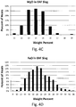
- FIG. 4A through 4F show the amount of the measured slag component for a plurality of heats at the EAF.
- the prior process provides lime, calcium aluminate, aluminum, slag deoxidant and ferrosilicon additions to the steel composition during tapping, and the steel composition in the ladle is stirred throughout the tapping process to mix the additions with the steel composition.
- the steel composition is desirably not stirred during tapping.
- no flux additions are typically made during the present tapping step.
- the steel composition is tapped open at the furnace, without deoxidizing additions.
- the tapping open step reduces the ability for desulfurization in the ladle prior to the VTD.
- the sulfur content of the steel composition was typically reduced from approximately 350 ppm to 160 ppm (0.035% to 0.016% by weight) in the ladle before the VTD step.
- the steel composition is transported in a ladle to the VTD for further treatment to reduce carbon, hydrogen and nitrogen content and desulfurize the steel composition.
- VTD vacuum arc degassing
- VOD vacuum oxygen decarburization
- the ladle may be transported by a vehicle or an overhead crane. Upon arrival at the VTD, the ladle may be moved via an overhead crane and placed in the VTD tank.
- the flow of argon causes an initial stirring to break-up and liquefy the slag, and make the steel temperature more even through the ladle.
- the porous plugs When the slag becomes broken-up and/or liquefied, the porous plugs are turned off, and measurements of the temperature and amount of oxygen are recorded. These measurements at the VTD and the measurements at the furnace recorded before and/or after tapping may be used to determine the alloy and flux additions to the steel composition, and used to determine the amount of time for the decarburization step at the VTD.
- the decarburization step is performed at the VTD followed by a deoxidation step, a slag building step, a desulfurizing step, and a gas removal step at the VTD.
- the decarburization process may begin after the argon stirring is turned off and measurements of the temperature and amount of oxygen are recorded in the steel composition at the VTD.
- the lid is placed onto the ladle, and the tank evacuation begins.
- gases are removed from the steel composition in the ladle, including carbon monoxide (CO), hydrogen, and nitrogen.
- CO carbon monoxide
- hydrogen hydrogen
- nitrogen As the vapor pressure of CO is reduced above the steel composition, additional carbon and oxygen react to form CO, which is drawn from the steel composition.
- Vacuum levels of less than 300 torr (about 400 millibars) are used during decarburization.
- the vacuum level may be a desired value, such as between about 150 and 300 torr (about 200 and 400 millibars), and then as decarburization progresses the vacuum may be pumped down to about 0.5 torr or higher or lower as desired for the decarburizing activity in the molten steel.
- the decarburization begins at about 200 torr (about 270 millibars for about 4 minutes, then is pumped down to about 0.5 torr, or lower, for the remainder of the decarburization.
- desired additives are added to the steel composition for deoxidization and desulfurization. Desired combinations of lime, dolomitic lime, silicomanganese, ferrosilicomanganese (FeSiMn) and other fluxes are also added to form a desulfurizing slag. Additives are selected to control and restrict the amount of aluminum in the slag and in the steel. Additions are added to the steel composition in the ladle through a pressure equalization hopper at desired times in the process. The addition of deoxidizing additives under vacuum can be reactive. Prior to adding the deoxidizing additives, the vacuum level may be adjusted to between about 20 and 150 torr (about 25 and 200 millibar), as desired for the additive composition.
- the tank lid is placed into its operating position.
- the porous plugs are turned on and the tank evacuation begins.
- the vacuum level is pumped down to less than about 5 torr for desulfurization and degassing, reducing at least sulfur, nitrogen, oxygen, and hydrogen contents.
- desulfurization and degassing may be at vacuum levels of 0.2 to 2 torr.
- the pump down time to 2 torr is typically less than 7 minutes, depending in part on the thermal history of the tank.
- the time to complete the desulfurization and degassing step may be about 20 minutes.
- stirring may be applied to the ladle.
- the stirring step includes bubbling inert gas at a rate between 0.1 and 1.0 SCFM (0.0028 m3/min to 0.0283 m3/min) per ton of molten metal in a heat for between 10 and 40 minutes.
- the stirring step may reduce the sulfur in the molten steel to less than 30 ppm, and alternatively less than 10 ppm, nitrogen to less than 50 ppm, activity of oxygen less than 15 ppm, and hydrogen less than 3 ppm.
- the activity of oxygen of the molten steel measured after degassing is lower than prior desulfurization methods for silicon killed steel.
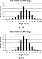
- FIGS. 5A through 5H show the amount of the measured slag component for a plurality of heats following the desulfurization and degassing step.
- the ladle may be transported to a Ladle Metallurgical Furnace (LMF) for further alloying and heating to the required casting temperatures.
- LMF Ladle Metallurgical Furnace
- further slag conditioners may be provided to reduce transfer of sulfur back to the steel during oxygen blow.
- Calcium may be added to kill the slag prior to oxygen blow.
- oxygen may be added to the molten steel as desired for the desired steel properties. In one application, oxygen is added to provide an active oxygen level of up to 70 ppm.
- Oxygen may be added to the molten steel by oxygen gas injection through a lance.
- oxygen gas may be added to the steel through one or more porous plugs.
- the oxygen may be added in a mixture with argon or other inert gas through the porous plug.
- oxygen may be added to the molten steel by the addition of metal oxides such as iron oxides, manganese oxides, molybdenum oxides, or other oxides, or combinations thereof as desired for the steel composition.
- the oxides may be provided by oxide powder in a cored wire fed into the molten steel using a typical wire feeder known in the art. In this application, the oxides may alternatively be injected through a lance.
- a carrier gas such as argon, may be provided with the oxides through the lance for delivering the powdered oxides through the lance. Injecting oxides using a cored wire delivery may be useful for applications requiring smaller amounts of oxygen addition, whereas injection of oxides through a lance may enable greater oxide additions.
- the slag composition includes CaO between about 50 and 70% by weight, SiO 2 between about 20 and 28% by weight, CaF 2 between about 5 and 15% by weight, MgO not more than 8% by weight, Al 2 O 3 not more than 1% by weight, and a combination of FeO + MnO not more than 2% by weight, where the sum of CaO + CaF 2 + SiO 2 + MgO is at least 85% of the slag composition by weight.
- the slag composition may include SO3 less than 4.0%.
- the present slag composition is typically a liquid under vacuum.
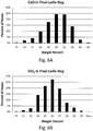
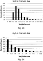
- FIGS. 6A through 6H show the amount of the measured slag component for a plurality of heats after processing in the LMF.
- the slag composition typically not more than 1% Al 2 O 3 by weight
- aluminum content in the steel is less than 0.01 % by weight, and may be less than 0.002% by weight.
- the ratio of manganese to silicon in the steel may be between about 3.5 and 6.
- the ratio of manganese to sulfur is greater than 200.
- the molten steel has an activity of oxygen between 15 and 70 ppm.
Landscapes
- Chemical & Material Sciences (AREA)
- Engineering & Computer Science (AREA)
- Materials Engineering (AREA)
- Metallurgy (AREA)
- Organic Chemistry (AREA)
- Manufacturing & Machinery (AREA)
- Treatment Of Steel In Its Molten State (AREA)
Description
- The present invention relates to desulfurizing steel.
- Certain commercial steel compositions require relatively low amounts of carbon (less than 0.05%), nitrogen (less than 50 ppm), and sulfur (less than 30 ppm). In the past, the process for producing these low carbon and low sulfur steels used a combination of processing steps in a steelmaking furnace and a degasser. The prior process involves reducing the carbon levels in the steel composition in the steelmaking furnace, such as an electric arc furnace (EAF), making alloy additions during the tapping process to desulfurize and alloy the steel, and then shipping the steel to the degasser such as a vacuum tank degasser (VTD). This processing route was simple and quite straightforward.
- To achieve the steel composition requirements of such commercial grades in the past, steel with very low carbon levels, such as less than 0.025%, was tapped at the steelmaking furnace. The dissolved oxygen levels associated with these low carbon amounts were in the order of 1200 ppm to 1400 ppm in the furnace before tapping. Where the degasser was a distance from the furnace, the steel was tapped at approximately 1700 °C to compensate for temperature losses during transportation to the degasser. During the tapping process, the steel was deoxidized with aluminum and ferrosilicon (FeSi). Lime and aluminum dross were also added to create a fluid, deoxidized, desulfurizing slag. By these additions, the desulfurizing reaction was started in the ladle during shipping to the degasser. At the degasser further additions of aluminum, lime, calcium aluminate and dolomitic lime were made to ensure desired sulfur removal during the degassing cycle.
- The prior process had drawbacks, including high refractory wear on the steelmaking furnace. The elevated tapping temperatures and high oxygen content required before tapping the steelmaking furnace had an adverse effect on productivity at the furnaces. The high temperatures and high oxygen conditions enabled high amounts of FeO in the slag at the high temperatures, causing excessive refractory wear on the furnace walls. This led to increased furnace down-times while the furnace refractories were patched with gunite. Also the high FeO content in the slag results in lower efficiency in steelmaking as more iron units are lost in the slag.
- The prior process also required the use of low carbon alloys and additives throughout the subsequent processes from the steelmaking furnace to maintain the low carbon level below 0.05% by weight. Low carbon alloying elements, such as low carbon FeMn, were required to provide desired elements without upsetting the final carbon content of the steel. Recently, the price of low carbon ferro-alloys has increased significantly, making this method economically undesirable to produce such low carbon steel. Further, lowering the amount of carbon in the steel composition in the steelmaking furnace required additional decarburization time, which also adversely affected productivity at the steelmaking furnace. Cost was further increased as a result of more silicon and aluminum required to deoxidize the steel composition as a result of the higher oxygen content.
- Additionally, in prior decarburizing and desulfurizing processes, aluminum has been the primary deoxidant. In certain applications, aluminum is not desired in the steel product, requiring additional compositions and processes to retain the aluminum in the slag. There remains a need to decrease production costs of low carbon, low nitrogen, and low sulfur steels.
-
JP H11 131132 -
CN 101020940 discloses a method of deoxidising and desulfurizing steel including ranges of aluminium additions to the steel/slag melt during the method. - We have found an alternative method of making a steel with low carbon less than 0.05% by weight that avoids the need for aluminum additives, reduces wear on refractories, and increases steelmaking efficiency.
- According to the present invention there is provided a method of desulfurizing a silicon killed steel according to
claim 1 - The step of drawing a vacuum may include drawing a vacuum to less than 1 torr.
- The stirring step may reduce lead, zinc, bismuth, antimony content in the molten steel composition.
- The stirring step may involve bubbling inert gas at a rate between 0.1 and 1.0 SCFM (0.0028 m3/min to 0.0283 m3/min) per ton of molten steel in a heat for between 10 and 40 minutes. The stirring step may reduce sulfur to less than 30 ppm, and alternatively less than 10 ppm, nitrogen to less than 50 ppm, activity of oxygen to less than 15 ppm, and hydrogen to less than 3 ppm.
- A method of desulfurizing a silicon killed steel may include the steps of:
- forming a slag over a molten metal,
- drawing a vacuum to less than 5 torr over the combination of slag and molten metal,
- stirring the molten metal and slag, and
- deoxidizing and desulfurizing the molten metal and slag to degas the metal reducing at least sulfur, nitrogen, oxygen, and hydrogen contents, and reducing activity of oxygen in the molten metal to less than 30 ppm, and
- forming a slag composition after degassing the metal and slag comprising:
- CaO between about 50 and 70% by weight,
- SiO2 between about 20 and 28% by weight,
- CaF2 between about 5 and 15% by weight,
- MgO not more than 8% by weight,
- Al2O3 not more than 1% by weight,
- Cr2O3 not more than 15% by weight, and
- a combination of FeO + MnO not more than 2% by weight,
- where the sum of CaO + CaF2 + SiO2 + MgO + Cr2O3 is at least 85% by weight.
- The method of desulfurizing steel may include the further steps of:
- (a) preparing a heat of molten steel composition in a steelmaking furnace to a tapping temperature as desired for desulfurization at a vacuum tank degasser,
- (b) tapping open into a ladle the molten steel composition with an oxygen level between 250 and 1200 ppm,
- (c) providing a slag forming compound to the ladle to form a slag cover over the molten steel composition in the ladle,
- (d) transporting the molten steel composition in the ladle to a vacuum tank degasser,
- (e) decarburizing the molten steel composition at the vacuum tank degasser by drawing a vacuum of between 0.5 and 300 torr,
- (f) after decarburizing, drawing a vacuum of less than 5 torr and adding flux components, deoxidizers, and alloying agents forming a slag composition having less than 1% Al2O3 to the molten steel to deoxidize and desulfurize the steel, and
- (g) stirring the molten steel and slag composition deoxidizing and desulfurizing the molten steel and slag composition to degas the steel reducing at least sulfur, nitrogen, oxygen, and hydrogen contents, and capable of reducing activity of oxygen to less than 30 ppm.
- The step of decarburizing the molten steel may be between 2 and 10 minutes.
- Depending on the final chemistry, the method may further include the step of prior to the step of decarburizing, adding an additional oxygen source.
- The step of adding flux components, deoxidizers, and alloying agents may include providing an initial slag composition prior to deoxidizing adapted to provide a slag composition after degassing the steel comprising:
- CaO between 50 and 70% by weight,
- SiO2 between 20 and 28% by weight,
- CaF2 between 5 and 15% by weight,
- MgO not more than 8% by weight,
- Al2O3 not more than 1% by weight, and
- a combination of FeO + MnO not more than 2%,
- where the sum of CaO + CaF2 + SiO2 + MgO is at least 85% by weight.
- The step of adding flux components, deoxidizers, and alloying agents may include providing an initial slag composition prior to deoxidizing adapted to provide a slag composition after degassing the steel comprising:
- CaO between 50 and 70% by weight,
- SiO2 between 20 and 28% by weight,
- CaF2 between 5 and 15% by weight,
- MgO not more than 8% by weight,
- Al2O3 not more than 1% by weight,
- Cr2O3 not more than 15% by weight, and
- a combination of FeO + MnO not more than 2% by weight,
- where the sum of CaO + CaF2 + SiO2 + MgO + Cr2O3 is at least 85% by weight.
- A method of preparing steel includes the methods of desulfurizing steel described in the preceding paragraphs.
IN order that the invention may be well understood, there will now be described an embodiment thereof, given by way of example, reference being made to the accompanying drawings, in which: -
-
FIG. 1 is a diagrammatical flowchart of processes used in one embodiment of the method of desulfurizing a silicon killed steel in accordance with the invention, -
FIG. 2 is a chart showing a distribution of tap temperatures for a plurality of heats, -
FIG. 3 is a chart showing a distribution of tap oxygen content for a plurality of heats, -
FIG. 4A through 4F are charts each showing a distribution of the amount of a component in a slag for a plurality of heats measured at the EAF, -
FIG. 5A through 5H are charts each showing a distribution of the amount of a component in a slag for a plurality of heats measured after degassing the molten steel, and -
FIG. 6A through 6H are charts each showing a distribution of the amount of a component in a slag for a plurality of heats measured prior to casting. - In the embodiment of the method of the method of desulfurizing a silicon killed steel for casting in accordance with the invention shown diagrammatically in
FIG. 1 , molten steel typically is prepared in an electric arc furnace (EAF) and is transsferred from the EAF to a vacuum tank degasser (VTD) and is processed in the VTD and then is transferred from the VTD to a ladle metallurgical furnace (LMF) and processed in the LMF before casting. - The steel grades produced by the presently disclosed embodiment of the method of the invention typically have carbon less than about 0.05% by weight. The steel grades also typically have low nitrogen less than about 0.005% by weight and low sulfur less than about 0.003% by weight, or less than about 0.0015% by weight.
- A steel melt shop typically has one or more electric arc furnaces, such as a 120 ton (metric ton) EAF equipped with 110 megavolt-ampere (MVA) transformers. Such electric arc furnaces may be between about 30 ton and 400 ton capacity, but are generally for continuous casting between 60 and 120 tons capacity. Each furnace may contain gas injection lances, such as a More brand gas injector system, through which a combination of oxygen and natural gas can be blown into the furnace, as well as a carbon injection pipe. These may be used to inject carbon and oxygen at different ratios throughout the heating of the steel to create a foamy EAF slag. Preparation of a foamy slag has been described in Pretorius, E.B. and R.C. Carlisle, Foamy Slag Fundamentals and Their Practical Application to Electric Furnace Steelmaking, IS S-AIME, EF Conference Proceedings, 1998, pp. 275-291. The EAF may also be equipped with a top feed flux system through which lime, dolomite and carbon can be fed to control the slag basicity and viscosity for better slag foaming while melting. The present process may be used with other steelmaking furnaces, such as a basic oxygen furnace.
- In the presently disclosed embodiment of the method of the invention the molten steel in the heat of an EAF is tapped open when the oxygen content and temperature of the steel composition are within desired parameter ranges. As the EAF may be a distance away from the VTD, the tapping temperature of the steel composition at the EAF is selected to allow for a temperature decrease during transit from the EAF to the VTD to provide a desired temperature at the VTD for decarburization and nitrogen and sulfur reduction. The steel composition may be tapped open from the furnace into a ladle through an eccentric bottom tap hole (EBT) system, which is typically designed to minimize carry-over slag from the EAF into the ladle during tapping. For example, in a 120 ton capacity EAF, about 95 ton of steel is tapped from the furnace into the ladle.
- When the VTD is a distance from the steelmaking furnace, the tap temperature may be between about 3100 °F and 3180 °F (about 1700 °C and 1750 °C) to allow for a temperature decrease during transit from the furnace to the VTD. Alternatively, when the transit time to the VTD is less, the tap temperature may be between about 2900 °F and 3000 °F (about 1590 °C and 1650 °C), or alternatively between about 3000 °F and 3100 °F (about 1650 °C and 1700 °C).
FIG. 2 shows a typical distribution of tap temperatures at the EAF. In the example shown inFIG. 2 , a majority of tap temperatures are between about 3040 °F and 3120 °F (about 1670 °C and 1715 °C). During the present tapping step, the argon plugs are shut off so that the steel composition may not be stirred. As soon as tapping from the furnace into the ladle is completed, a steel sample may be taken, and an addition of slag forming compound such as lime added to the ladle to cover the steel to reduce heat losses and oxidation during transportation to the VTD. A lid may desirably be placed onto the ladle before its transport to the VTD. - In the presently disclosed embodiment of the method of the invention, decarburization is not completed in the EAF as in the prior process. Instead, in the presently disclosed embodiment the EAF tap oxygen is lowered with correspondingly higher tap carbon levels. This improved method includes the steps of open tapping at the steelmaking furnace and subsequent decarburization, deoxidation, and desulfurization steps at the VTD. Open tapping (or tapping open) means tapping without an intentional addition of deoxidizers. In the presently disclosed embodiment, the tap oxygen content of the steel is between about 250 and 1200 ppm, and more desirably between about 700 and 1000 ppm. For tap oxygen levels lower than about 700 ppm, prior to the step of decarburizing, an additional oxygen source may be added to the ladle, such as mill scale.
FIG. 3 shows a typical distribution of tap oxygen content at the EAF. - The ladles are typically equipped with two porous plugs capable of introducing argon into the steel composition as desired. The porous plug hook-up may use automated connections through corresponding ladle trunnions. The tap station is also equipped with a measurement system capable of measuring and recording the steel temperature directly after tapping, and may be capable of measuring and recording additional information such as oxygen level in the steel composition. As soon as the tapping process is completed, a slag sample may be taken from the EAF to measure the amount of FeO in the EAF slag.
FIG. 4A through 4F show the amount of the measured slag component for a plurality of heats at the EAF. - The prior process provides lime, calcium aluminate, aluminum, slag deoxidant and ferrosilicon additions to the steel composition during tapping, and the steel composition in the ladle is stirred throughout the tapping process to mix the additions with the steel composition. By contrast, in the presently disclosed embodiment, the steel composition is desirably not stirred during tapping. Additionally, other than an addition of lime or dolomitic lime to cover the steel in the ladle, no flux additions are typically made during the present tapping step.
- In the presently disclosed embodiment, the steel composition is tapped open at the furnace, without deoxidizing additions. As discussed below, the tapping open step reduces the ability for desulfurization in the ladle prior to the VTD. In the prior process involving a deoxidant addition to the ladle and stirring the metal and slag to provide some amount of desulfurization before the VTD, the sulfur content of the steel composition was typically reduced from approximately 350 ppm to 160 ppm (0.035% to 0.016% by weight) in the ladle before the VTD step.
- In the presently disclosed embodiment, after the tapping step, the steel composition is transported in a ladle to the VTD for further treatment to reduce carbon, hydrogen and nitrogen content and desulfurize the steel composition. While the presently disclosed embodiment herein is described with reference to a VTD, it is to be understood that the method of the invention is not limited thereto. The method of the invention may be adapted to other degassing systems, including: vacuum arc degassing (VAD) and vacuum oxygen decarburization (VOD). The ladle may be transported by a vehicle or an overhead crane. Upon arrival at the VTD, the ladle may be moved via an overhead crane and placed in the VTD tank.
- Once in the VTD porous plug connections may be made, the plugs opened and argon introduced through the porous plugs in the steel composition in the ladle using argon gas at flow rates typically of less than 1 m3/min, i.e. between about 10 and 35 SCFM (0.28 m3/min to 0.99 m3/min), but may be up to 2.3 m3/min (about 80 SCFM (about 2,27 m3/min)) for certain applications. The flow of argon causes an initial stirring to break-up and liquefy the slag, and make the steel temperature more even through the ladle. When the slag becomes broken-up and/or liquefied, the porous plugs are turned off, and measurements of the temperature and amount of oxygen are recorded. These measurements at the VTD and the measurements at the furnace recorded before and/or after tapping may be used to determine the alloy and flux additions to the steel composition, and used to determine the amount of time for the decarburization step at the VTD.
- In the presently disclosed embodiment, the decarburization step is performed at the VTD followed by a deoxidation step, a slag building step, a desulfurizing step, and a gas removal step at the VTD.
- The decarburization process may begin after the argon stirring is turned off and measurements of the temperature and amount of oxygen are recorded in the steel composition at the VTD. The lid is placed onto the ladle, and the tank evacuation begins. As a vacuum is drawn on the ladle, gases are removed from the steel composition in the ladle, including carbon monoxide (CO), hydrogen, and nitrogen. As the vapor pressure of CO is reduced above the steel composition, additional carbon and oxygen react to form CO, which is drawn from the steel composition. We have found that the reaction of carbon and oxygen provides sufficient stirring action and no argon stirring is required. However, for certain applications some argon stirring may be desired. Vacuum levels of less than 300 torr (about 400 millibars) are used during decarburization. At the beginning of decarburization, the vacuum level may be a desired value, such as between about 150 and 300 torr (about 200 and 400 millibars), and then as decarburization progresses the vacuum may be pumped down to about 0.5 torr or higher or lower as desired for the decarburizing activity in the molten steel. In one example, the decarburization begins at about 200 torr (about 270 millibars for about 4 minutes, then is pumped down to about 0.5 torr, or lower, for the remainder of the decarburization.
- After decarburization in the VTD, desired additives are added to the steel composition for deoxidization and desulfurization. Desired combinations of lime, dolomitic lime, silicomanganese, ferrosilicomanganese (FeSiMn) and other fluxes are also added to form a desulfurizing slag. Additives are selected to control and restrict the amount of aluminum in the slag and in the steel. Additions are added to the steel composition in the ladle through a pressure equalization hopper at desired times in the process. The addition of deoxidizing additives under vacuum can be reactive. Prior to adding the deoxidizing additives, the vacuum level may be adjusted to between about 20 and 150 torr (about 25 and 200 millibar), as desired for the additive composition.
- As the desired additions are fed from the hopper, the tank lid is placed into its operating position. The porous plugs are turned on and the tank evacuation begins. The vacuum level is pumped down to less than about 5 torr for desulfurization and degassing, reducing at least sulfur, nitrogen, oxygen, and hydrogen contents. Alternatively, desulfurization and degassing may be at vacuum levels of 0.2 to 2 torr. The pump down time to 2 torr is typically less than 7 minutes, depending in part on the thermal history of the tank. The time to complete the desulfurization and degassing step may be about 20 minutes.
- During the desulfurization and degassing in the presently disclosed embodiment, stirring may be applied to the ladle. The stirring step includes bubbling inert gas at a rate between 0.1 and 1.0 SCFM (0.0028 m3/min to 0.0283 m3/min) per ton of molten metal in a heat for between 10 and 40 minutes. The stirring step may reduce the sulfur in the molten steel to less than 30 ppm, and alternatively less than 10 ppm, nitrogen to less than 50 ppm, activity of oxygen less than 15 ppm, and hydrogen less than 3 ppm. The activity of oxygen of the molten steel measured after degassing is lower than prior desulfurization methods for silicon killed steel.
- As an example,
FIGS. 5A through 5H show the amount of the measured slag component for a plurality of heats following the desulfurization and degassing step. - Then, the ladle may be transported to a Ladle Metallurgical Furnace (LMF) for further alloying and heating to the required casting temperatures. At the LMF, further slag conditioners may be provided to reduce transfer of sulfur back to the steel during oxygen blow. Calcium may be added to kill the slag prior to oxygen blow.
- In the LMF, after desired alloying elements are added and slag conditioned, oxygen may be added to the molten steel as desired for the desired steel properties. In one application, oxygen is added to provide an active oxygen level of up to 70 ppm.
- Oxygen may be added to the molten steel by oxygen gas injection through a lance. Alternatively, oxygen gas may be added to the steel through one or more porous plugs. In this alternative, the oxygen may be added in a mixture with argon or other inert gas through the porous plug. In yet another alternative, oxygen may be added to the molten steel by the addition of metal oxides such as iron oxides, manganese oxides, molybdenum oxides, or other oxides, or combinations thereof as desired for the steel composition. In one application, the oxides may be provided by oxide powder in a cored wire fed into the molten steel using a typical wire feeder known in the art. In this application, the oxides may alternatively be injected through a lance. A carrier gas, such as argon, may be provided with the oxides through the lance for delivering the powdered oxides through the lance. Injecting oxides using a cored wire delivery may be useful for applications requiring smaller amounts of oxygen addition, whereas injection of oxides through a lance may enable greater oxide additions.
- Following the desulfurization and degassing step in the presently disclosed embodiment, the slag composition includes CaO between about 50 and 70% by weight, SiO2 between about 20 and 28% by weight, CaF2 between about 5 and 15% by weight, MgO not more than 8% by weight, Al2O3 not more than 1% by weight, and a combination of FeO + MnO not more than 2% by weight, where the sum of CaO + CaF2 + SiO2 + MgO is at least 85% of the slag composition by weight. The slag composition may include SO3 less than 4.0%. The present slag composition is typically a liquid under vacuum. As an example,
FIGS. 6A through 6H show the amount of the measured slag component for a plurality of heats after processing in the LMF. - In the presently disclosed embodiment, while a limited amount of aluminum is tolerated in the slag composition (typically not more than 1% Al2O3 by weight), for most applications there is no purposeful addition of aluminum in the slag composition. The aluminum content in the steel is less than 0.01 % by weight, and may be less than 0.002% by weight. The ratio of manganese to silicon in the steel may be between about 3.5 and 6. The ratio of manganese to sulfur is greater than 200. In addition, the molten steel has an activity of oxygen between 15 and 70 ppm.
Claims (12)
- A method of desulfurizing a silicon killed steel comprising the steps of:forming a slag over a molten steel,drawing a vacuum to less than 5 torr over the combination of slag and molten steel,stirring the molten steel and slag,deoxidizing and desulfurizing the molten steel and slag to degas the steel reducing at least sulfur, nitrogen, oxygen, and hydrogen contents, and reducing activity of oxygen in the molten steel to less than 30 ppm, andforming a slag composition after degassing the steel comprising:CaO between 50 and 70% by weight,SiO2 between 20 and 28% by weight,CaF2 between 5 and 15% by weight,MgO not more than 8% by weight,Al2O3 not more than 1% by weight, anda combination of FeO + MnO not more than 2% by weight,where the sum of CaO + CaF2 + SiO2 + MgO is at least 85% by weight.
- The method of desulfurizing steel of claim 1, where the step of drawing a vacuum includes drawing a vacuum to less than 1 torr.
- The method of desulfurizing steel of claim 1 or claim 2, where the stirring step reduces lead, zinc, bismuth, antimony contents in the molten steel composition.
- The method of desulfurizing steel of any one of the preceding claims, where the stirring step involves bubbling inert gas at a rate between 0.1 and 1.0 SCFM (between 0.0028 m3/min and 0.0283 m3/min) per ton of molten steel in a heat for between 10 and 40 minutes.
- The method of desulfurizing steel of any one of the preceding claims, where the stirring step reduces sulfur to less than 30 ppm, nitrogen to less than 50 ppm, activity of oxygen to less than 15 ppm, and hydrogen to less than 3 ppm.
- The method of desulfurizing steel of any one of the preceding claims, where the slag composition after degassing the steel further comprises Cr2O3 not more than 15% by weight and where the sum of CaO + CaF2 + SiO2 + MgO + Cr2O3 is at least 85% by weight.
- The method of desulfurizing steel of claim 1, comprising the steps of:(a) preparing a heat of molten steel composition in a steelmaking furnace to a tapping temperature as desired for desulfurization at a vacuum tank degasser,(b) tapping open into a ladle the molten steel composition with an oxygen level between 250 and 1200 ppm,(c) providing a slag forming compound to the ladle to form a slag cover over the molten steel composition in the ladle,(d) transporting the molten steel composition in the ladle to a vacuum tank degasser,(e) decarburizing the molten steel composition at the vacuum tank degasser by drawing a vacuum of between 0.5 and 300 torr,(f) after decarburizing, drawing the vacuum of less than 5 torr defined in claim 1 and adding flux components, deoxidizers, and alloying agents forming the slag defined in claim 1 with a composition having less than 1% Al2O3 to the molten steel, and(g) stirring the molten steel and slag composition and deoxidizing and desulfurizing the molten steel and slag composition to degas the steel reducing at least sulfur, nitrogen, oxygen, and hydrogen contents, and reducing activity of oxygen to less than 30 ppm and(g) forming the slag composition defined in claim 1 after degassing the steel.
- The method of desulfurizing steel of claim 7, where the step of decarburizing the molten steel is between 2 and 10 minutes.
- The method of desulfurizing steel of claim 7 or claim 8, further comprising the step of: prior to the step of decarburizing, adding an additional oxygen source.
- The method of desulfurizing steel of claim 9, where the additional oxygen source is selected from the group consisting of oxygen gas, metal oxides, or a combination thereof.
- The method of desulfurizing steel of any one of claims 7 to 10, where the step of adding flux components, deoxidizers, and alloying agents includes:
providing the initial slag composition prior to deoxidizing adapted to provide the slag composition after degassing the steel further comprising:Cr2O3 not more than 15% by weight, andwhere the sum of CaO + CaF2 + SiO2 + MgO + Cr2O3 is at least 85% by weight. - The method of desulfurizing steel of any one of the preceding claims, where the steel composition at the end of the method steps contains less than 0.05% carbon and/or less than 50 ppm nitrogen and/or. less than 30 ppm sulfur.
Priority Applications (1)
| Application Number | Priority Date | Filing Date | Title |
|---|---|---|---|
| PL12734204T PL2663662T3 (en) | 2011-01-14 | 2012-01-12 | Method of desulfurizing steel |
Applications Claiming Priority (3)
| Application Number | Priority Date | Filing Date | Title |
|---|---|---|---|
| US201113007163A | 2011-01-14 | 2011-01-14 | |
| US13/106,352 US8523977B2 (en) | 2011-01-14 | 2011-05-12 | Method of desulfurizing steel |
| PCT/AU2012/000019 WO2012094705A1 (en) | 2011-01-14 | 2012-01-12 | Method of desulfurizing steel |
Publications (3)
| Publication Number | Publication Date |
|---|---|
| EP2663662A1 EP2663662A1 (en) | 2013-11-20 |
| EP2663662A4 EP2663662A4 (en) | 2015-12-02 |
| EP2663662B1 true EP2663662B1 (en) | 2019-03-06 |
Family
ID=46489727
Family Applications (1)
| Application Number | Title | Priority Date | Filing Date |
|---|---|---|---|
| EP12734204.6A Active EP2663662B1 (en) | 2011-01-14 | 2012-01-12 | Method of desulfurizing steel |
Country Status (9)
| Country | Link |
|---|---|
| US (1) | US8523977B2 (en) |
| EP (1) | EP2663662B1 (en) |
| JP (1) | JP2014509345A (en) |
| CN (1) | CN103403194B (en) |
| AU (1) | AU2012206947B2 (en) |
| MX (1) | MX2013007475A (en) |
| PL (1) | PL2663662T3 (en) |
| RU (1) | RU2608865C2 (en) |
| WO (1) | WO2012094705A1 (en) |
Families Citing this family (9)
| Publication number | Priority date | Publication date | Assignee | Title |
|---|---|---|---|---|
| US20130167688A1 (en) * | 2012-01-04 | 2013-07-04 | Gregory Dressel | Method of making low carbon steel using ferrous oxide and mineral carbonates |
| PL2985359T3 (en) * | 2013-04-11 | 2019-03-29 | Posco | Manganese-containing molten steel production method |
| CZ2013531A3 (en) * | 2013-07-08 | 2015-02-04 | Ecofer, S.R.O. | Agglomerate flux, flux manufacturing method, agglomerate agglomerate blend and secondary metallurgical slag as fluxes for agglomeration |
| CN111194357A (en) * | 2017-08-24 | 2020-05-22 | 纽科尔公司 | Improved manufacturing of mild steel |
| CN107904410B (en) * | 2017-11-03 | 2019-10-08 | 中信锦州金属股份有限公司 | A kind of compound degasser prepares the production method of high temperature alloy and the dedicated high-purity metal chromium of target |
| CN112795721A (en) * | 2020-12-30 | 2021-05-14 | 唐山燕山钢铁有限公司 | Smelting method of L415M-HLT steel grade |
| JP7480751B2 (en) | 2021-06-11 | 2024-05-10 | Jfeスチール株式会社 | METHOD FOR DENITRATION OF MOLTEN STEEL AND METHOD FOR PRODUCING STEEL |
| CN114086052B (en) * | 2021-12-03 | 2022-11-15 | 宝钢德盛不锈钢有限公司 | Smelting method of low-density stainless steel |
| CN116004938B (en) * | 2022-12-31 | 2025-11-11 | 四川钒盛新材料有限公司 | Vanadium extraction slag regulating agent and preparation method thereof |
Family Cites Families (30)
| Publication number | Priority date | Publication date | Assignee | Title |
|---|---|---|---|---|
| US3793000A (en) | 1972-06-12 | 1974-02-19 | Nat Steel Corp | Process for preparing killed low carbon steel and continuously casting the same, and the solidified steel shapes thus produced |
| AT331438B (en) | 1973-06-14 | 1976-08-25 | Voest Ag | CONTINUOUS STEEL CONTINUOUS STEEL CASTING PROCESS AND SYSTEM FOR IMPLEMENTING THE PROCESS |
| US4043798A (en) | 1974-09-20 | 1977-08-23 | Sumitomo Metal Industries Limited | Process for producing steel having improved low temperature impact characteristics |
| IT1047585B (en) | 1975-09-26 | 1980-10-20 | Centro Speriment Metallurg | PERFECTION FOR DEOXIDATION AND DESULFURATION OF STEEL |
| AU517323B2 (en) | 1976-07-28 | 1981-07-23 | Nippon Steel Corporation | Producing killed steels for continuous casting |
| US4612043A (en) | 1984-03-29 | 1986-09-16 | Pennsylvania Engineering Corporation | Steel making method |
| US4695318A (en) | 1986-10-14 | 1987-09-22 | Allegheny Ludlum Corporation | Method of making steel |
| US5110351A (en) | 1991-01-10 | 1992-05-05 | Usx Corporation | Method of promoting the decarburization reaction in a vacuum refining furnace |
| JP3002593B2 (en) | 1992-02-19 | 2000-01-24 | 川崎製鉄株式会社 | Melting method of ultra low carbon steel |
| US5304231A (en) * | 1991-12-24 | 1994-04-19 | Kawasaki Steel Corporation | Method of refining of high purity steel |
| AU653294B2 (en) | 1992-08-26 | 1994-09-22 | Nippon Steel Corporation | Process for vacuum degassing molten steel |
| US5228902A (en) | 1992-09-03 | 1993-07-20 | Usx Corporation | Method of desulfurization in vacuum processing of steel |
| US5472479A (en) | 1994-01-26 | 1995-12-05 | Ltv Steel Company, Inc. | Method of making ultra-low carbon and sulfur steel |
| US5520718A (en) | 1994-09-02 | 1996-05-28 | Inland Steel Company | Steelmaking degassing method |
| US5851262A (en) | 1994-11-25 | 1998-12-22 | Hitachi Metals, Ltd. | Method of refining molten metal |
| JPH0941028A (en) * | 1995-07-28 | 1997-02-10 | Sumitomo Metal Ind Ltd | Highly clean ultra low carbon steel manufacturing method |
| US6179895B1 (en) | 1996-12-11 | 2001-01-30 | Performix Technologies, Ltd. | Basic tundish flux composition for steelmaking processes |
| JPH11131132A (en) | 1997-10-27 | 1999-05-18 | Daido Steel Co Ltd | Steel desulfurization method |
| JP3896713B2 (en) | 1998-12-16 | 2007-03-22 | 住友金属工業株式会社 | Melting method of ultra-low carbon steel with excellent cleanability |
| JP2001342510A (en) | 2000-06-02 | 2001-12-14 | Nisshin Steel Co Ltd | Method for smelting metal |
| RU21915U1 (en) * | 2001-07-16 | 2002-02-27 | Магнитогорский государственный технический университет им. Г.И. Носова | PLANT FOR THE PRODUCTION OF LOW CARBON STEEL |
| JP4753504B2 (en) | 2001-09-14 | 2011-08-24 | 日新製鋼株式会社 | Method for producing high purity Fe-Cr, Fe-Cr-Ni alloy |
| KR100711410B1 (en) | 2004-12-09 | 2007-04-30 | 가부시키가이샤 고베 세이코쇼 | Highly Ductile Steel Sheet and Method of Manufacturing the Same |
| UA77127C2 (en) * | 2005-05-30 | 2006-10-16 | Anatolii Tymofiiovych Neklesa | Method for out-of-furnace steel treatment |
| CN100436603C (en) * | 2007-03-28 | 2008-11-26 | 北京科技大学 | Process of deoxygenating, desulfurizing and controlling non-metal inclusion content in steel |
| CN100529111C (en) | 2007-10-16 | 2009-08-19 | 攀枝花新钢钒股份有限公司 | A special slagging agent for desulfurization of vanadium, titanium and magnesium iron |
| CN101545027A (en) | 2008-03-24 | 2009-09-30 | 宝山钢铁股份有限公司 | Low-carbon quick melting ladle refining slag |
| UA104595C2 (en) * | 2008-08-04 | 2014-02-25 | Ньюкор Корпорейшн | method for making a steel with low carbon low sulphur low nitrogen using conventional steelmaking Equipment |
| KR101689633B1 (en) * | 2008-08-04 | 2016-12-26 | 누코 코포레이션 | Low cost making of a low carbon, low sulfur, and low nitrogen steel using conventional steelmaking equipment |
| US8105415B2 (en) * | 2008-08-04 | 2012-01-31 | Nucor Corporation | Low cost making of a low carbon, low sulfur, and low nitrogen steel using conventional steelmaking equipment |
-
2011
- 2011-05-12 US US13/106,352 patent/US8523977B2/en active Active
-
2012
- 2012-01-12 WO PCT/AU2012/000019 patent/WO2012094705A1/en not_active Ceased
- 2012-01-12 JP JP2013548704A patent/JP2014509345A/en active Pending
- 2012-01-12 RU RU2013137852A patent/RU2608865C2/en not_active IP Right Cessation
- 2012-01-12 AU AU2012206947A patent/AU2012206947B2/en not_active Ceased
- 2012-01-12 EP EP12734204.6A patent/EP2663662B1/en active Active
- 2012-01-12 MX MX2013007475A patent/MX2013007475A/en active IP Right Grant
- 2012-01-12 CN CN201280005796.9A patent/CN103403194B/en active Active
- 2012-01-12 PL PL12734204T patent/PL2663662T3/en unknown
Non-Patent Citations (1)
| Title |
|---|
| None * |
Also Published As
| Publication number | Publication date |
|---|---|
| CN103403194A (en) | 2013-11-20 |
| WO2012094705A1 (en) | 2012-07-19 |
| AU2012206947A1 (en) | 2013-08-15 |
| US20120180601A1 (en) | 2012-07-19 |
| EP2663662A4 (en) | 2015-12-02 |
| MX2013007475A (en) | 2013-08-15 |
| AU2012206947B2 (en) | 2016-06-30 |
| EP2663662A1 (en) | 2013-11-20 |
| JP2014509345A (en) | 2014-04-17 |
| US8523977B2 (en) | 2013-09-03 |
| RU2608865C2 (en) | 2017-01-25 |
| RU2013137852A (en) | 2015-02-20 |
| PL2663662T3 (en) | 2019-10-31 |
| CN103403194B (en) | 2016-08-03 |
Similar Documents
| Publication | Publication Date | Title |
|---|---|---|
| AU2012206947B2 (en) | Method of desulfurizing steel | |
| EP2331715B2 (en) | Low cost making of a low carbon, low sulfur, and low nitrogen steel using conventional steelmaking equipment | |
| AU2011267833B2 (en) | Low cost making of a low carbon, low sulfur, and low nitrogen steel using conventional steelmaking equipment | |
| US8313553B2 (en) | Low cost making of a low carbon, low sulfur, and low nitrogen steel using conventional steelmaking equipment | |
| JP5910579B2 (en) | Melting method of ultra-low nitrogen pure iron | |
| JP6028755B2 (en) | Method for melting low-sulfur steel | |
| JPH07216434A (en) | Ultra low carbon ultra low sulfur steel manufacturing method | |
| JP2012184501A (en) | Method for desulfurizing molten steel | |
| CN110621793A (en) | Smelting method of high manganese steel | |
| JP5343308B2 (en) | Desulfurization method for molten steel | |
| US20130167688A1 (en) | Method of making low carbon steel using ferrous oxide and mineral carbonates | |
| JP4742740B2 (en) | Method for melting low-sulfur steel | |
| JP2012077354A (en) | Method for melting/preparing low carbon aluminum killed steel excellent in cleanliness | |
| JP4534734B2 (en) | Melting method of low carbon high manganese steel | |
| JP2015232157A (en) | Dephosphorization method of molten steel using vacuum degasification facility | |
| JP4765374B2 (en) | Desulfurization treatment method for chromium-containing hot metal | |
| CN105714016A (en) | Low-cost method for making steel with low carbon low sulphur low nitrogen using conventional steelmaking Equipment | |
| JPH0633132A (en) | Method of deoxidizing molten steel |
Legal Events
| Date | Code | Title | Description |
|---|---|---|---|
| PUAI | Public reference made under article 153(3) epc to a published international application that has entered the european phase |
Free format text: ORIGINAL CODE: 0009012 |
|
| 17P | Request for examination filed |
Effective date: 20130715 |
|
| AK | Designated contracting states |
Kind code of ref document: A1 Designated state(s): AL AT BE BG CH CY CZ DE DK EE ES FI FR GB GR HR HU IE IS IT LI LT LU LV MC MK MT NL NO PL PT RO RS SE SI SK SM TR |
|
| DAX | Request for extension of the european patent (deleted) | ||
| RA4 | Supplementary search report drawn up and despatched (corrected) |
Effective date: 20151104 |
|
| RIC1 | Information provided on ipc code assigned before grant |
Ipc: C21C 7/076 20060101ALI20151029BHEP Ipc: C21C 7/10 20060101ALI20151029BHEP Ipc: C21C 7/06 20060101ALI20151029BHEP Ipc: C21C 7/064 20060101AFI20151029BHEP Ipc: C21C 5/54 20060101ALI20151029BHEP |
|
| STAA | Information on the status of an ep patent application or granted ep patent |
Free format text: STATUS: EXAMINATION IS IN PROGRESS |
|
| 17Q | First examination report despatched |
Effective date: 20170614 |
|
| GRAP | Despatch of communication of intention to grant a patent |
Free format text: ORIGINAL CODE: EPIDOSNIGR1 |
|
| STAA | Information on the status of an ep patent application or granted ep patent |
Free format text: STATUS: GRANT OF PATENT IS INTENDED |
|
| INTG | Intention to grant announced |
Effective date: 20181002 |
|
| GRAS | Grant fee paid |
Free format text: ORIGINAL CODE: EPIDOSNIGR3 |
|
| GRAA | (expected) grant |
Free format text: ORIGINAL CODE: 0009210 |
|
| STAA | Information on the status of an ep patent application or granted ep patent |
Free format text: STATUS: THE PATENT HAS BEEN GRANTED |
|
| AK | Designated contracting states |
Kind code of ref document: B1 Designated state(s): AL AT BE BG CH CY CZ DE DK EE ES FI FR GB GR HR HU IE IS IT LI LT LU LV MC MK MT NL NO PL PT RO RS SE SI SK SM TR |
|
| REG | Reference to a national code |
Ref country code: GB Ref legal event code: FG4D |
|
| REG | Reference to a national code |
Ref country code: CH Ref legal event code: EP Ref country code: AT Ref legal event code: REF Ref document number: 1104621 Country of ref document: AT Kind code of ref document: T Effective date: 20190315 |
|
| REG | Reference to a national code |
Ref country code: IE Ref legal event code: FG4D |
|
| REG | Reference to a national code |
Ref country code: DE Ref legal event code: R096 Ref document number: 602012057438 Country of ref document: DE |
|
| REG | Reference to a national code |
Ref country code: NL Ref legal event code: MP Effective date: 20190306 |
|
| REG | Reference to a national code |
Ref country code: LT Ref legal event code: MG4D |
|
| PG25 | Lapsed in a contracting state [announced via postgrant information from national office to epo] |
Ref country code: SE Free format text: LAPSE BECAUSE OF FAILURE TO SUBMIT A TRANSLATION OF THE DESCRIPTION OR TO PAY THE FEE WITHIN THE PRESCRIBED TIME-LIMIT Effective date: 20190306 Ref country code: LT Free format text: LAPSE BECAUSE OF FAILURE TO SUBMIT A TRANSLATION OF THE DESCRIPTION OR TO PAY THE FEE WITHIN THE PRESCRIBED TIME-LIMIT Effective date: 20190306 Ref country code: FI Free format text: LAPSE BECAUSE OF FAILURE TO SUBMIT A TRANSLATION OF THE DESCRIPTION OR TO PAY THE FEE WITHIN THE PRESCRIBED TIME-LIMIT Effective date: 20190306 Ref country code: NO Free format text: LAPSE BECAUSE OF FAILURE TO SUBMIT A TRANSLATION OF THE DESCRIPTION OR TO PAY THE FEE WITHIN THE PRESCRIBED TIME-LIMIT Effective date: 20190606 |
|
| PG25 | Lapsed in a contracting state [announced via postgrant information from national office to epo] |
Ref country code: RS Free format text: LAPSE BECAUSE OF FAILURE TO SUBMIT A TRANSLATION OF THE DESCRIPTION OR TO PAY THE FEE WITHIN THE PRESCRIBED TIME-LIMIT Effective date: 20190306 Ref country code: BG Free format text: LAPSE BECAUSE OF FAILURE TO SUBMIT A TRANSLATION OF THE DESCRIPTION OR TO PAY THE FEE WITHIN THE PRESCRIBED TIME-LIMIT Effective date: 20190606 Ref country code: NL Free format text: LAPSE BECAUSE OF FAILURE TO SUBMIT A TRANSLATION OF THE DESCRIPTION OR TO PAY THE FEE WITHIN THE PRESCRIBED TIME-LIMIT Effective date: 20190306 Ref country code: LV Free format text: LAPSE BECAUSE OF FAILURE TO SUBMIT A TRANSLATION OF THE DESCRIPTION OR TO PAY THE FEE WITHIN THE PRESCRIBED TIME-LIMIT Effective date: 20190306 Ref country code: HR Free format text: LAPSE BECAUSE OF FAILURE TO SUBMIT A TRANSLATION OF THE DESCRIPTION OR TO PAY THE FEE WITHIN THE PRESCRIBED TIME-LIMIT Effective date: 20190306 |
|
| REG | Reference to a national code |
Ref country code: GR Ref legal event code: EP Ref document number: 20190401685 Country of ref document: GR Effective date: 20190906 |
|
| PG25 | Lapsed in a contracting state [announced via postgrant information from national office to epo] |
Ref country code: RO Free format text: LAPSE BECAUSE OF FAILURE TO SUBMIT A TRANSLATION OF THE DESCRIPTION OR TO PAY THE FEE WITHIN THE PRESCRIBED TIME-LIMIT Effective date: 20190306 Ref country code: IT Free format text: LAPSE BECAUSE OF FAILURE TO SUBMIT A TRANSLATION OF THE DESCRIPTION OR TO PAY THE FEE WITHIN THE PRESCRIBED TIME-LIMIT Effective date: 20190306 Ref country code: CZ Free format text: LAPSE BECAUSE OF FAILURE TO SUBMIT A TRANSLATION OF THE DESCRIPTION OR TO PAY THE FEE WITHIN THE PRESCRIBED TIME-LIMIT Effective date: 20190306 Ref country code: AL Free format text: LAPSE BECAUSE OF FAILURE TO SUBMIT A TRANSLATION OF THE DESCRIPTION OR TO PAY THE FEE WITHIN THE PRESCRIBED TIME-LIMIT Effective date: 20190306 Ref country code: SK Free format text: LAPSE BECAUSE OF FAILURE TO SUBMIT A TRANSLATION OF THE DESCRIPTION OR TO PAY THE FEE WITHIN THE PRESCRIBED TIME-LIMIT Effective date: 20190306 Ref country code: PT Free format text: LAPSE BECAUSE OF FAILURE TO SUBMIT A TRANSLATION OF THE DESCRIPTION OR TO PAY THE FEE WITHIN THE PRESCRIBED TIME-LIMIT Effective date: 20190706 Ref country code: ES Free format text: LAPSE BECAUSE OF FAILURE TO SUBMIT A TRANSLATION OF THE DESCRIPTION OR TO PAY THE FEE WITHIN THE PRESCRIBED TIME-LIMIT Effective date: 20190306 Ref country code: EE Free format text: LAPSE BECAUSE OF FAILURE TO SUBMIT A TRANSLATION OF THE DESCRIPTION OR TO PAY THE FEE WITHIN THE PRESCRIBED TIME-LIMIT Effective date: 20190306 |
|
| PG25 | Lapsed in a contracting state [announced via postgrant information from national office to epo] |
Ref country code: SM Free format text: LAPSE BECAUSE OF FAILURE TO SUBMIT A TRANSLATION OF THE DESCRIPTION OR TO PAY THE FEE WITHIN THE PRESCRIBED TIME-LIMIT Effective date: 20190306 |
|
| REG | Reference to a national code |
Ref country code: DE Ref legal event code: R097 Ref document number: 602012057438 Country of ref document: DE |
|
| PG25 | Lapsed in a contracting state [announced via postgrant information from national office to epo] |
Ref country code: IS Free format text: LAPSE BECAUSE OF FAILURE TO SUBMIT A TRANSLATION OF THE DESCRIPTION OR TO PAY THE FEE WITHIN THE PRESCRIBED TIME-LIMIT Effective date: 20190706 |
|
| PLBE | No opposition filed within time limit |
Free format text: ORIGINAL CODE: 0009261 |
|
| STAA | Information on the status of an ep patent application or granted ep patent |
Free format text: STATUS: NO OPPOSITION FILED WITHIN TIME LIMIT |
|
| PG25 | Lapsed in a contracting state [announced via postgrant information from national office to epo] |
Ref country code: DK Free format text: LAPSE BECAUSE OF FAILURE TO SUBMIT A TRANSLATION OF THE DESCRIPTION OR TO PAY THE FEE WITHIN THE PRESCRIBED TIME-LIMIT Effective date: 20190306 |
|
| 26N | No opposition filed |
Effective date: 20191209 |
|
| PG25 | Lapsed in a contracting state [announced via postgrant information from national office to epo] |
Ref country code: SI Free format text: LAPSE BECAUSE OF FAILURE TO SUBMIT A TRANSLATION OF THE DESCRIPTION OR TO PAY THE FEE WITHIN THE PRESCRIBED TIME-LIMIT Effective date: 20190306 |
|
| PG25 | Lapsed in a contracting state [announced via postgrant information from national office to epo] |
Ref country code: TR Free format text: LAPSE BECAUSE OF FAILURE TO SUBMIT A TRANSLATION OF THE DESCRIPTION OR TO PAY THE FEE WITHIN THE PRESCRIBED TIME-LIMIT Effective date: 20190306 |
|
| REG | Reference to a national code |
Ref country code: DE Ref legal event code: R119 Ref document number: 602012057438 Country of ref document: DE |
|
| PG25 | Lapsed in a contracting state [announced via postgrant information from national office to epo] |
Ref country code: MC Free format text: LAPSE BECAUSE OF FAILURE TO SUBMIT A TRANSLATION OF THE DESCRIPTION OR TO PAY THE FEE WITHIN THE PRESCRIBED TIME-LIMIT Effective date: 20190306 |
|
| REG | Reference to a national code |
Ref country code: CH Ref legal event code: PL |
|
| REG | Reference to a national code |
Ref country code: BE Ref legal event code: MM Effective date: 20200131 |
|
| PG25 | Lapsed in a contracting state [announced via postgrant information from national office to epo] |
Ref country code: FR Free format text: LAPSE BECAUSE OF NON-PAYMENT OF DUE FEES Effective date: 20200131 Ref country code: LU Free format text: LAPSE BECAUSE OF NON-PAYMENT OF DUE FEES Effective date: 20200112 Ref country code: DE Free format text: LAPSE BECAUSE OF NON-PAYMENT OF DUE FEES Effective date: 20200801 |
|
| PG25 | Lapsed in a contracting state [announced via postgrant information from national office to epo] |
Ref country code: CH Free format text: LAPSE BECAUSE OF NON-PAYMENT OF DUE FEES Effective date: 20200131 Ref country code: LI Free format text: LAPSE BECAUSE OF NON-PAYMENT OF DUE FEES Effective date: 20200131 Ref country code: BE Free format text: LAPSE BECAUSE OF NON-PAYMENT OF DUE FEES Effective date: 20200131 |
|
| REG | Reference to a national code |
Ref country code: AT Ref legal event code: UEP Ref document number: 1104621 Country of ref document: AT Kind code of ref document: T Effective date: 20190306 |
|
| PG25 | Lapsed in a contracting state [announced via postgrant information from national office to epo] |
Ref country code: IE Free format text: LAPSE BECAUSE OF NON-PAYMENT OF DUE FEES Effective date: 20200112 |
|
| REG | Reference to a national code |
Ref country code: AT Ref legal event code: MM01 Ref document number: 1104621 Country of ref document: AT Kind code of ref document: T Effective date: 20200112 |
|
| PG25 | Lapsed in a contracting state [announced via postgrant information from national office to epo] |
Ref country code: AT Free format text: LAPSE BECAUSE OF NON-PAYMENT OF DUE FEES Effective date: 20200112 |
|
| PG25 | Lapsed in a contracting state [announced via postgrant information from national office to epo] |
Ref country code: PL Free format text: LAPSE BECAUSE OF NON-PAYMENT OF DUE FEES Effective date: 20200112 Ref country code: MT Free format text: LAPSE BECAUSE OF FAILURE TO SUBMIT A TRANSLATION OF THE DESCRIPTION OR TO PAY THE FEE WITHIN THE PRESCRIBED TIME-LIMIT Effective date: 20190306 Ref country code: CY Free format text: LAPSE BECAUSE OF FAILURE TO SUBMIT A TRANSLATION OF THE DESCRIPTION OR TO PAY THE FEE WITHIN THE PRESCRIBED TIME-LIMIT Effective date: 20190306 |
|
| PG25 | Lapsed in a contracting state [announced via postgrant information from national office to epo] |
Ref country code: MK Free format text: LAPSE BECAUSE OF FAILURE TO SUBMIT A TRANSLATION OF THE DESCRIPTION OR TO PAY THE FEE WITHIN THE PRESCRIBED TIME-LIMIT Effective date: 20190306 |
|
| PGFP | Annual fee paid to national office [announced via postgrant information from national office to epo] |
Ref country code: GB Payment date: 20250128 Year of fee payment: 14 |
|
| PGFP | Annual fee paid to national office [announced via postgrant information from national office to epo] |
Ref country code: GR Payment date: 20260220 Year of fee payment: 15 |