EP2663243B1 - Anastomose latéro-latérale - Google Patents
Anastomose latéro-latérale Download PDFInfo
- Publication number
- EP2663243B1 EP2663243B1 EP11701880.4A EP11701880A EP2663243B1 EP 2663243 B1 EP2663243 B1 EP 2663243B1 EP 11701880 A EP11701880 A EP 11701880A EP 2663243 B1 EP2663243 B1 EP 2663243B1
- Authority
- EP
- European Patent Office
- Prior art keywords
- graft vessel
- ring
- pins
- wall
- connector
- Prior art date
- Legal status (The legal status is an assumption and is not a legal conclusion. Google has not performed a legal analysis and makes no representation as to the accuracy of the status listed.)
- Active
Links
Images


Classifications
-
- A—HUMAN NECESSITIES
- A61—MEDICAL OR VETERINARY SCIENCE; HYGIENE
- A61F—FILTERS IMPLANTABLE INTO BLOOD VESSELS; PROSTHESES; DEVICES PROVIDING PATENCY TO, OR PREVENTING COLLAPSING OF, TUBULAR STRUCTURES OF THE BODY, e.g. STENTS; ORTHOPAEDIC, NURSING OR CONTRACEPTIVE DEVICES; FOMENTATION; TREATMENT OR PROTECTION OF EYES OR EARS; BANDAGES, DRESSINGS OR ABSORBENT PADS; FIRST-AID KITS
- A61F2/00—Filters implantable into blood vessels; Prostheses, i.e. artificial substitutes or replacements for parts of the body; Appliances for connecting them with the body; Devices providing patency to, or preventing collapsing of, tubular structures of the body, e.g. stents
- A61F2/02—Prostheses implantable into the body
- A61F2/04—Hollow or tubular parts of organs, e.g. bladders, tracheae, bronchi or bile ducts
- A61F2/06—Blood vessels
- A61F2/064—Blood vessels with special features to facilitate anastomotic coupling
-
- A—HUMAN NECESSITIES
- A61—MEDICAL OR VETERINARY SCIENCE; HYGIENE
- A61B—DIAGNOSIS; SURGERY; IDENTIFICATION
- A61B17/00—Surgical instruments, devices or methods
- A61B17/064—Surgical staples, i.e. penetrating the tissue
-
- A—HUMAN NECESSITIES
- A61—MEDICAL OR VETERINARY SCIENCE; HYGIENE
- A61B—DIAGNOSIS; SURGERY; IDENTIFICATION
- A61B17/00—Surgical instruments, devices or methods
- A61B17/11—Surgical instruments, devices or methods for performing anastomosis; Buttons for anastomosis
-
- A—HUMAN NECESSITIES
- A61—MEDICAL OR VETERINARY SCIENCE; HYGIENE
- A61F—FILTERS IMPLANTABLE INTO BLOOD VESSELS; PROSTHESES; DEVICES PROVIDING PATENCY TO, OR PREVENTING COLLAPSING OF, TUBULAR STRUCTURES OF THE BODY, e.g. STENTS; ORTHOPAEDIC, NURSING OR CONTRACEPTIVE DEVICES; FOMENTATION; TREATMENT OR PROTECTION OF EYES OR EARS; BANDAGES, DRESSINGS OR ABSORBENT PADS; FIRST-AID KITS
- A61F2/00—Filters implantable into blood vessels; Prostheses, i.e. artificial substitutes or replacements for parts of the body; Appliances for connecting them with the body; Devices providing patency to, or preventing collapsing of, tubular structures of the body, e.g. stents
- A61F2/02—Prostheses implantable into the body
- A61F2/04—Hollow or tubular parts of organs, e.g. bladders, tracheae, bronchi or bile ducts
- A61F2/06—Blood vessels
- A61F2/062—Apparatus for the production of blood vessels made from natural tissue or with layers of living cells
-
- A—HUMAN NECESSITIES
- A61—MEDICAL OR VETERINARY SCIENCE; HYGIENE
- A61B—DIAGNOSIS; SURGERY; IDENTIFICATION
- A61B17/00—Surgical instruments, devices or methods
- A61B17/08—Wound clamps or clips, i.e. not or only partly penetrating the tissue ; Devices for bringing together the edges of a wound
- A61B17/083—Clips, e.g. resilient
-
- A—HUMAN NECESSITIES
- A61—MEDICAL OR VETERINARY SCIENCE; HYGIENE
- A61B—DIAGNOSIS; SURGERY; IDENTIFICATION
- A61B17/00—Surgical instruments, devices or methods
- A61B2017/00743—Type of operation; Specification of treatment sites
- A61B2017/00778—Operations on blood vessels
-
- A—HUMAN NECESSITIES
- A61—MEDICAL OR VETERINARY SCIENCE; HYGIENE
- A61B—DIAGNOSIS; SURGERY; IDENTIFICATION
- A61B17/00—Surgical instruments, devices or methods
- A61B17/11—Surgical instruments, devices or methods for performing anastomosis; Buttons for anastomosis
- A61B2017/1107—Surgical instruments, devices or methods for performing anastomosis; Buttons for anastomosis for blood vessels
-
- A—HUMAN NECESSITIES
- A61—MEDICAL OR VETERINARY SCIENCE; HYGIENE
- A61B—DIAGNOSIS; SURGERY; IDENTIFICATION
- A61B17/00—Surgical instruments, devices or methods
- A61B17/11—Surgical instruments, devices or methods for performing anastomosis; Buttons for anastomosis
- A61B2017/1139—Side-to-side connections, e.g. shunt or X-connections
Definitions
- the invention relates to the field of side-to-side (abbreviated as STS) anastomosing.
- STS side-to-side
- a STS-anastomosis is a in the medical field a connection between two channels, in general blood vessels, which are connected with their sides against each other. In the region where the sides of the vessels lie against each other there is an aperture allowing blood to flow from the one vessel into the other vessel. STS-anastomoses are frequently used in the field of bypass surgery for example on the heart.
- the object of the invention is to provide a reliable manner for making an anastomosis. According to a first aspect, this object is achieved by providing an assembly of a graft vessel and an anastomosis connector according to claim 1. According to a second aspect, this object is achieved by providing a method of making (such) an assembly according to claim 12.
- an "anastomosis connector of the type comprising a ring and two pins" wherein each pin has a free end and a fixed end connected to the ring, wherein the pins extend, viewed from the fixed end towards the free end, next to and set apart from each other; and wherein each pin has an overlap section where the pin, viewed in axial direction of the ring, overlaps the plane bounded by the outer contour of the ring.
- An assembly according to claim 1 enables making a side-to-side anastomosis connection in an easy manner which requires relative little time and results in a very safe and reliable anastomosis.
- the graft vessel can be an artificial vessel or a biological vessel.
- the graft vessel can also be made from a combination of biological and artificial material.
- a biological vessel it is noted that this can originate from a human or animal donor - other than the patient itself -, but it can also originate from the patient itself, like a saphenous vein from the leg or an internal mammary artery from the chest.
- the graft vessel can according to the invention also be a vessel having a biologically cultured cell layer grown onto a supporting tube, like a harness or gauze structure.
- the assembly according to the invention also in case a graft vessel originating from the patient itself, is prepared completely outside the patient and without being connected in any manner to the patient.
- the assembly according to the invention can of course be made in the operation room during the operation just beside he patient itself, but it can also be made remote from the patient in a laboratory, factory or other suitable facility during or before the operation.
- the wall of the graft vessel is provided with an opening surrounded by the ring.
- this opening can have been formed by laser cutting an opening into the wall of the graft vessel.
- the connector is attached to the graft vessel by sutures attaching the ring onto the wall of the graft vessel.
- the connector is attached to the graft vessel by adhesive adhering the ring onto the wall of the graft vessel.
- This attachment by adhesive can according to the invention also be combined with the above mentioned attachment by sutures but the attachment with adhesive can also be without attachment by sutures.
- the connector is attached to the graft vessel by the pins piercing through the wall of the graft vessel.
- This attachment by the pins can according to the invention also be combined with the above mentioned attachment by sutures and/or adhesive, but the attachment with the pins can also be without attachment by sutures and/or adhesive.
- Using the pins for attachment of the connector to the graft vessel may allow, after attachment of the assembly according to the invention to the recipient vessel, wall tissue of both the recipient vessel and the graft vessel being clamped between the pins and the ring of the connector. This may improve the tightness of the connection as well the connection being leak free. Further this may support - after the operation - growth of the tissue of the graft vessel and recipient vessel into integral new tissue.
- the pins extend in the longitudinal direction of the graft vessel. This allows the pins to be longer than the diameter of the ring. Pins longer than the diameter of he ring may be practical when attaching the assembly according to the invention to the recipient vessel.
- the ring lies against the outer surface of the wall of the graft vessel. This is easy to establish. Further it allows the operator when attaching the assembly to the recipient vessel a good view on the location of attachment.
- the a part of the wall of the graft vessel lying inside the region surrounded by the ring covers the inside of the ring.
- the pins might stay uncovered. It might even be folded over 180° around the ring to fully cover the ring whilst leaving the pins uncovered. In this way, internal wall tissue of the graft vessel will prevent blood, flowing through the anastomotic connection, from contacting the ring.
- the ring lies against the inner surface of the wall of the graft vessel and the pins lie outside the graft vessel and extend parallel to the outer surface of the wall of the graft vessel.
- this may allow, after attachment of the assembly according to the invention to the recipient vessel, wall tissue of both the recipient vessel and the graft vessel being clamped between the pins and the ring of the connector. This may improve the tightness of the connection as well the connection being leak free. Further this may support - after the operation - growth of the tissue of the graft vessel and recipient vessel into integral new tissue.
- the graft vessel has a first end and a second end; wherein the pins, viewed from the fixed ends towards the free ends of the pins, extend towards the second end; and wherein the distance from the connector to the first end of the graft vessel is smaller than the distance from the connector to the second end.
- the distance from the connector to the first end is at least 0.5 cm.
- the distance from the connector to the first end is at least 1.0 cm.
- a rod like application member could be inserted through an end of the graft vessel into the lumen of the graft vessel.
- the invention provides a method of making an assembly comprising on the one hand a graft vessel and on the other hand an anastomosis connector; wherein the graft is during the complete method of making the assembly, separated from human or animal body; wherein the connector comprises a ring and two pins; each pin having a free end and a fixed end connected to the ring; the pins extending, viewed from the fixed end towards the free end, next to and set apart from each other; each pin having an overlap section where the pin, viewed in axial direction of the ring, overlaps the plane bounded by the outer contour of the ring; wherein the method comprises the step of:
- the step of making said opening can comprise burning with a laser, such as an Excimer laser, an opening through the wall of the graft vessel.
- the step of attaching the connector to the graft vessel comprises:
- the step of attaching the connector to the graft vessel comprises:
- the ring is placed against the outside of the graft vessel when performing the step of attaching the connector to the graft vessel.
- the step of attaching the connector to the graft vessel can comprise the step of covering the inside of the ring with a part of the wall of the graft vessel lying inside the region surrounded by the ring.
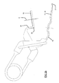
- Figure 1 shows schematically a human heart 1.
- No. 2 indicates the aorta and no. 3 and no. 4 are both a coronary artery which is blocked at 5 respectively 6.
- a bypass 7 has been made to bypass blockage 5 and a bypass 8 has been made to bypass blockage 6.
- graft vessel 9 is prepared according to the invention completely outside and separated from the body of the patient. This preparation can for example take place at a location where the patient is not present, but it can also take place close to the patient in the operating room.
- the term 'the graft vessel being separated from a human or animal body' and the term 'the graft vessel being separated from the body of the patient' as used in this application means that the graft vessel is a separate entity not attached to a human/animal/patient body. Of coarse these term(s) do not exclude that somebody can keep it in his hand or manipulate it. These term(s) mean that the graft is, when separated, not part of the biological system of a body of a human/animal/patient.
- graft vessel 12 For bypass 8 an internal mammary artery from the chest has been used as graft vessel 12. At location 13 this graft vessel has a natural connection to the aorta. Thus at this location no artificial anastomotic connection is required. At location 14 an exemplary anastomotic connection has been made. Graft vessel 12 may be prepared inside the body of the patient or completely outside the body of the patient, but graft vessel 12 will stay connected at location 13 with the patient.
- coronary artery 4 is the recipient vessel with respect to graft vessel 12 and coronary artery 3 and aorta 2 are each a recipient vessels with respect to graft vessel 9.
- FIG. 2a shows schematically a connector 15 that can be used according to the invention.
- This connector 15 comprises a ring 16 and two pins 17, 18 which are with the so called fixed end 22 attached to the ring 16 at 20, and extend from the fixed end 20 towards the pointed free end 21, next to and set apart from each other in the same direction.
- the pins 17, 18 have an overlap section 19 in which they overlap the plane bounded by the ring.
- the plane bounded by the ring is as such defined as the plane 'surface' lying inside the ring and the ring itself. The plane bounded by the ring thus does not extend outside the ring.
- Axis A is the axial axis of the ring.
- a connector 15 like the one as shown in figure 2a is also known from WO 2009/123434 . All the securing devices as disclosed in WO 2009/12434 can be used as a connector for the present invention.
- connector 15 shown in figure 2a is also shown in the figures 3 , 4 and 5 - to be discussed below, it is noted that connectors of the according to the invention can also be of different design, as follows from the example of the connector shown in figure 2b .
- FIG. 2b For details of figure 2b reference is made to WO 2011/062495 .
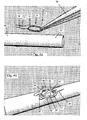
- Figure 3 illustrates a first method of making an assembly according to the invention.
- Figure 3a shows a graft vessel 30, the connector 15 of figure 2a and the gripper end of a forceps 32.
- the forceps 32 holds the connector 15 and inserts the connector 15 in the direction of arrow B into the lumen 33 of graft vessel 30.
- Figure 3b shows that the pins 17 and 18 are pierced from inside the lumen of graft vessel 30 through the wall 34 of the graft vessel 30 to outside the graft vessel 30.
- the insertion movement in the direction B is continued to shift the connector further in the direction of insertion B up to the pins fully passed through the wall 34 of the graft vessel, see figure 3c .
- the pins have fully passed through the wall 34 of the graft vessel 30 and lie essentially parallel to the wall of the graft vessel 30.
- the ring 16 of the connector lies inside the graft vessel and is shown by dashed line for illustrative purpose.
- FIG. 3d shows that, in the region surrounded by the ring 16, an opening 35 has been made through the wall 34 of the graft vessel 30.
- This opening serves to allow blood to enter or leave the graft vessel at this place in order to allow blood flowing into or from the recipient vessel.
- This opening 35 can be made with an Excimer laser as mentioned earlier several times. The opening can also be made with another tool like a knife.
- Figure 3d further shows that sutures 36 can be used to attach the ring 16 against the inner side of the wall 34 of the graft vessel 30.
- the sutures 36 can be provided before or after making the opening 35.
- the opening 35 does not need to be made at this stage, it is also conceivable to make the opening after attaching the assembly of graft vessel 30 and connector 15 to the recipient vessel.
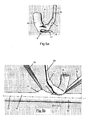
- Figure 4 illustrates a second method of making an assembly according to the invention.
- the main difference between the method illustrated with figure 3 and the method illustrated with figure 4 is that in the method of figure 3 the ring of the connector is arranged inside the graft vessel and the pins 17, 18 of the connector are arranged outside the graft vessel, whilst in the method of figure 4 the ring and pins are both arranged outside the graft vessel.
- Figure 4a shows a graft vessel 30, the connector 15 of figure 2a and the gripper end of a forceps 32.
- the forceps 32 holds the connector 15 and places the connector 15 in the direction of arrow C against the graft vessel 30 so that the ring 16 lies between the wall of the graft vessel 30 and the pins 17, 18.
- Fig 4b shows as a next step that an opening 35 has been made in the region of the wall of the graft vessel which surrounded by the ring.
- This opening 35 will later allow blood flow between the graft vessel and recipient vessel.
- the wall tissue of the graft vessel 30 in said region surrounded by the ring 16 is not removed, at least not fully removed.
- Parts 37, 38, and 39 of the wall tissue in said region are used to cover the inner side of the ring 16. Doing so the internal surface 40 of the parts 37, 38, 39 of wall tissue will face inwardly. After completing the anastomotic connection, it will be this internal surface 40 which contacts blood flowing through the anastomotic connection. This is favourable as this internal surface is the natural surface for contacting blood.
- sutures 36 are used on the one hand to attach the ring 16 to the graft vessel and on the other hand to keep the parts 37, 38 and 39 against the inner side of the ring. It is noted that in case the parts 37, 38, 39 have, in radial direction of the ring, sufficient length, they might be folded around the ring and inserted into the gap between the ring 16 and pins 17, 18.
- Figure 5 shows how to use an assembly according to the invention for attachment to a recipient vessel in order to accomplish a side-to-side anastomosis.
- the assembly shown in figure 5 is an assembly made according to figure 4
- an assembly made according to figure 3 can also be attached to the recipient vessel in the manner as illustrated in figure 5 .
- the parts 41 and 42 of the graft vessel 30, which lie adjacent the connector 15, may be folded towards the axial axis A of the ring 16, or said differently these parts 41 and 42 may be folded towards each other. This may provide the operator, who has to make the exemplary anastomotic connection, a better view onto the connector 15.
- Figure 5b shows in addition a recipient vessel 50 and two forceps 32.
- One of the forceps holds the connector 15 at its ring.
- the other foreceps grips a part 51 of the vessel wall 52 of the recipient vessel and pulls this part 51 away from the longitudinal axis 53 of the recipient vessel 50.
- this gripping and pulling of the part 51 is optional, it makes it easier to pierce the pins 17 and 18 into the wall of the recipient vessel.
- the assembly of graft vessel 30 and connector 15 may be shifted in the direction of arrow D. Once the pointed free ends of the pins passed from the outside through the vessel wall 52, the connector may be shifted further in the direction of arrow D. At the end of this shifting movement, the free ends of the pins 17, 18 can be pierced again through the vessel wall, but now from the inside to the outside. This condition is shown in figure 5d .
- Figure 5d further shows that a laser catheter 60 may be inserted into the part 42 of the graft vessel 40 to burn away that part of the wall of the recipient vessel lying in the region surrounded by the ring 16.
- a laser catheter 60 may be inserted into the part 42 of the graft vessel 40 to burn away that part of the wall of the recipient vessel lying in the region surrounded by the ring 16.
- US 5,964,750 show in more detail the manner of function of the laser catheter tip during application of laser light.
- a ring shaped cut is burnt and the vessel part lying inside this cut may be suctioned against a grid to remove it.
- the laser catheter may be withdrawn in direction E and the part 42 may be provided with a clip to prevent leakage of blood.
- Part 42 can also be closed by suturing, burning or other means in order to prevent blood from flowing out this end.
- the part 41 of the graft vessel might be temporarily closed, for example by a clip.
- graft vessel has sufficient length
- a double bypass also called a jump.
Landscapes
- Health & Medical Sciences (AREA)
- Life Sciences & Earth Sciences (AREA)
- Engineering & Computer Science (AREA)
- Biomedical Technology (AREA)
- Surgery (AREA)
- Veterinary Medicine (AREA)
- Public Health (AREA)
- General Health & Medical Sciences (AREA)
- Heart & Thoracic Surgery (AREA)
- Animal Behavior & Ethology (AREA)
- Nuclear Medicine, Radiotherapy & Molecular Imaging (AREA)
- Medical Informatics (AREA)
- Molecular Biology (AREA)
- Vascular Medicine (AREA)
- Transplantation (AREA)
- Oral & Maxillofacial Surgery (AREA)
- Cardiology (AREA)
- Pulmonology (AREA)
- Gastroenterology & Hepatology (AREA)
- Surgical Instruments (AREA)
- Prostheses (AREA)
Claims (16)
- Ensemble comprenant un vaisseau de greffe (30) et un connecteur d'anastomose (15) ;
dans lequel le vaisseau de greffe (30) est séparé d'un corps humain ou de celui d'un animal ;
dans lequel le connecteur (15) comprend un anneau (16) et deux broches (17, 18) ;
chaque broche (17, 18) comportant une extrémité libre (21) et une extrémité fixée (22) reliée à l'anneau (16) ;
les broches (17, 18) s'étendant, lorsqu'elles sont vues de l'extrémité fixée (22) vers l'extrémité libre (21), l'une à côté de l'autre et séparées l'une de l'autre ;
chaque broche (17, 18) comportant une section de recouvrement (19) où la broche, lorsqu'elle est vue dans une direction axiale de l'anneau (16), recouvre le plan délimité par le contour extérieur de l'anneau (16) ;
dans lequel le connecteur (15) est attaché au vaisseau de greffe (30) ;
dans lequel les broches (17, 18) sont agencées à l'extérieur du vaisseau de greffe (30) ; et
dans lequel l'anneau (16) se trouve, avec sa circonférence entière, contre la paroi (34) du vaisseau de greffe (30) ;
caractérisé en ce que l'axe axial de l'anneau (16) s'étend transversalement à la paroi (34) du vaisseau de greffe (30). - Ensemble selon la revendication 1, dans lequel la paroi (34) du vaisseau de greffe (30) est pourvue d'une ouverture (35) entourée par l'anneau (16), et dans lequel l'ouverture (35) a été de préférence formée par découpe au laser d'une ouverture (35) dans la paroi (34) du vaisseau de greffe (30).
- Ensemble selon l'une des revendications précédentes, dans lequel le connecteur (15) est attaché au vaisseau de greffe (30) par des points de suture (36) attachant l'anneau (16) sur la paroi (34) du vaisseau de greffe (30), et/ou en faisant adhérer par adhésif l'anneau (16) sur la paroi (34) du vaisseau de greffe (30), et/ou par les broches (17, 18) transperçant la paroi (34) du vaisseau de greffe (30).
- Ensemble selon l'une des revendications précédentes, dans lequel les broches (17, 18) s'étendent dans la direction longitudinale du vaisseau de greffe (30).
- Ensemble selon l'une des revendications précédentes, dans lequel l'anneau (16) se trouve contre la surface extérieure de la paroi (34) du vaisseau de greffe (30), et dans lequel une partie de la paroi (34) du vaisseau de greffe (30) se trouvant à l'intérieur d'une région entourée par l'anneau (16) est repliée vers l'extérieur pour recouvrir le côté intérieur de l'anneau (16).
- Ensemble selon l'une des revendications 1 à 4 précédentes, dans lequel l'anneau (16) se trouve contre la surface intérieure de la paroi (34) du vaisseau de greffe (30), et dans lequel les broches (17, 18) se trouvent à l'extérieur du vaisseau de greffe (30) et s'étendent parallèlement à la surface extérieure de la paroi (34) du vaisseau de greffe (30).
- Ensemble selon l'une des revendications précédentes, dans lequel le vaisseau de greffe (30) comporte une première extrémité et une deuxième extrémité ; dans lequel les broches (17, 18), lorsqu'elles sont vues des extrémités fixées (22) vers les extrémités libres (21), s'étendent vers la deuxième extrémité du vaisseau de greffe (30), et dans lequel la distance du connecteur (15) à la première extrémité du vaisseau de greffe (30) est inférieure à la distance du connecteur (15) à la deuxième extrémité, et dans lequel cette distance du connecteur (15) à la première extrémité est de préférence d'au moins 0,5 cm, telle que de 1,0 cm ou plus.
- Ensemble selon l'une des revendications précédentes, dans lequel, dans une première position des broches (17, 18) par rapport à l'anneau (16), au moins une partie des sections de recouvrement (19) s'étend parallèlement à l'anneau (16).
- Ensemble selon l'une des revendications précédentes, dans lequel les broches (17, 18) sont reliées rigidement à l'anneau (16).
- Ensemble selon l'une des revendications 1 à 8, dans lequel les broches (17, 18) peuvent être déplacées, par rapport à l'anneau (16), d'une première position à une deuxième position afin de former, entre l'anneau (16) et les broches (17, 18), une mâchoire ouverte ; et dans lequel les broches (17, 18) peuvent être déplacées de la deuxième position à la première position vers l'anneau (16) afin de fermer la mâchoire ; et
dans lequel, de préférence,
dans la deuxième position, les sections de recouvrement (19) des broches (17, 18) sont inclinées par rapport au plan défini par l'anneau (16) afin de former ladite mâchoire qui, lorsqu'elle est vue de l'extrémité fixée (22) vers l'extrémité libre (21), s'élargit, et dans lequel les broches (17, 18) peuvent pivoter, par rapport à l'anneau (16), de la deuxième position à la première position ;
et/ou
dans lequel le connecteur (15) comprend en outre un élément de tension qui, lorsque les broches (17, 18) sont dans la deuxième position, applique une pré-tension aux broches (17, 18) vers la première position. - Ensemble selon l'une des revendications précédentes, dans lequel les extrémités libres (21) des broches (17, 18) sont agencées à une distance de la section de recouvrement (19), dans lequel ladite distance est égale à au moins 50 % du rayon de l'anneau (16), de préférence à au moins 100 % du rayon de l'anneau (16) ; et dans lequel les sections des broches (17, 18) entre la section de recouvrement (19) et l'extrémité libre (21) de chaque broche sont de préférence sensiblement parallèles l'une à l'autre.
- Procédé de fabrication d'un ensemble comprenant un vaisseau de greffe (30) et un connecteur d'anastomose (15) ;
dans lequel la greffe est, pendant le procédé complet de fabrication de l'ensemble, séparée d'un corps humain ou de celui d'un animal ;
dans lequel le connecteur (15) comprend un anneau (16) et deux broches (17, 18) ; chaque broche (17, 18) ayant une extrémité libre (21) et une extrémité fixée (22) reliée à l'anneau (16) ; les broches (17, 18) s'étendant, lorsqu'elles sont vues de l'extrémité fixée (22) vers l'extrémité libre (21), l'une à côté de l'autre et séparées l'une de l'autre ; chaque broche (17, 18) comportant une section de recouvrement (19) où la broche, lorsqu'elle est vue dans une direction axiale de l'anneau (16), recouvre le plan délimité par le contour extérieur de l'anneau (16) ;
dans lequel le procédé comprend les étapes :. d'agencement de l'anneau (16) pour qu'il soit avec sa circonférence entière contre la paroi (34) du vaisseau de greffe (30) et avec son axe axial transversal à la paroi (34) du vaisseau de greffe (30) ; et. de fixation du connecteur (15) au vaisseau de greffe (30). - Procédé selon la revendication 12, comprenant en outre l'étape :. de formation d'une ouverture (35) à travers la paroi (34) du vaisseau de greffe (30) dans la région entourée par l'anneau (16) ;dans lequel l'étape de formation de ladite ouverture (35) est de préférence effectuée en brûlant avec un laser, tel qu'un laser à excimère, une ouverture (35) à travers la paroi (34) du vaisseau de greffe (30).
- Procédé selon l'une des revendications 12 et 13, dans lequel l'étape de fixation du connecteur (15) au vaisseau de greffe (30) comprend la suture de l'anneau (16) sur la paroi (34) du vaisseau de greffe (30) ; et/ou l'adhérence de l'anneau (16) sur la paroi (34) du vaisseau de greffe (30) ; et/ou le transpercement de la paroi (34) du vaisseau de greffe (30) par les broches (17, 18).
- Procédé selon l'une des revendications 12 à 14, dans lequel l'étape de fixation du connecteur (15) au vaisseau de greffe (30) comprend :. l'insertion du connecteur (15) dans la lumière du vaisseau de greffe (30), les extrémités libres (21) des broches (17, 18) pointant dans la direction d'insertion ;. le transpercement du vaisseau de greffe (30), par les extrémités libres (21) des broches (17, 18), de l'intérieur du vaisseau de greffe (30) à travers la paroi (34) du vaisseau de greffe (30) jusqu'à l'extérieur du vaisseau de greffe (30) et le décalage par la suite du connecteur (15) davantage dans la direction d'insertion jusqu'à ce que les broches (17, 18) aient entièrement traversé la paroi (34) du vaisseau de greffe (30) et que l'anneau (16) se trouve contre la surface intérieure de la paroi (34) du vaisseau de greffe (30).
- Procédé selon l'une des revendications 12 à 14, dans lequel, à l'étape de fixation du connecteur (15) au vaisseau de greffe (30), l'anneau (16) est placé contre l'extérieur du vaisseau de greffe (30) ; et l'étape de fixation du connecteur (15) au vaisseau de greffe (30) comprend en outre le recouvrement de l'intérieur de l'anneau (16) par une partie de la paroi (34) du vaisseau de greffe (30) se trouvant à l'intérieur de la région entourée par l'anneau (16).
Applications Claiming Priority (1)
| Application Number | Priority Date | Filing Date | Title |
|---|---|---|---|
| PCT/NL2011/050019 WO2012096563A1 (fr) | 2011-01-12 | 2011-01-12 | Anastomose côte à côte |
Publications (3)
| Publication Number | Publication Date |
|---|---|
| EP2663243A1 EP2663243A1 (fr) | 2013-11-20 |
| EP2663243B1 true EP2663243B1 (fr) | 2015-10-21 |
| EP2663243B8 EP2663243B8 (fr) | 2015-11-25 |
Family
ID=44583596
Family Applications (1)
| Application Number | Title | Priority Date | Filing Date |
|---|---|---|---|
| EP11701880.4A Active EP2663243B8 (fr) | 2011-01-12 | 2011-01-12 | Anastomose latéro-latérale |
Country Status (5)
| Country | Link |
|---|---|
| US (1) | US20130345499A1 (fr) |
| EP (1) | EP2663243B8 (fr) |
| JP (1) | JP2014507980A (fr) |
| CN (1) | CN203597993U (fr) |
| WO (1) | WO2012096563A1 (fr) |
Families Citing this family (3)
| Publication number | Priority date | Publication date | Assignee | Title |
|---|---|---|---|---|
| ES3041086T3 (en) * | 2016-06-13 | 2025-11-06 | Bolton Medical Inc | Devices for reinforcing fenestrations in prosthetic implants |
| WO2019060816A2 (fr) | 2017-09-25 | 2019-03-28 | Aortica Corporation | Systèmes, dispositifs et procédés pour coupler un implant prothétique à un corps fenêtré |
| NL2032224B1 (en) | 2022-06-20 | 2024-01-08 | Amt Medical B V | anastomosis clip |
Family Cites Families (8)
| Publication number | Priority date | Publication date | Assignee | Title |
|---|---|---|---|---|
| DE4408746C2 (de) | 1994-03-15 | 1997-06-05 | Medolas Ges Fuer Medizintechni | Laserkatheter zur Bypass-Chirurgie |
| US5964750A (en) | 1994-03-15 | 1999-10-12 | Medolas Gesellschaft Fuer Medizintechnik Gmbh | Laser catheter for bypass surgery |
| US6458140B2 (en) * | 1999-07-28 | 2002-10-01 | Vasconnect, Inc. | Devices and methods for interconnecting vessels |
| EP1628702B1 (fr) * | 2003-04-28 | 2013-05-01 | Erwin De Winter | Dispositif de vis d'ancrage |
| EP1547526A1 (fr) * | 2003-12-23 | 2005-06-29 | UMC Utrecht Holding B.V. | Elément d'opération, ensemble d'opération et son utilisation |
| US8777971B2 (en) * | 2006-10-17 | 2014-07-15 | Amj Bv | Device and method for joining vessels in anastomosis |
| WO2009012434A1 (fr) | 2007-07-19 | 2009-01-22 | Telcordia Technologies, Inc. | Procédé pour une infrastructure de clé publique fournissant intégrité et anonymat de communication tout en détectant une communication malveillante |
| ATE547053T1 (de) | 2008-04-03 | 2012-03-15 | Amj B V | Fixierungsvorrichtung und anordnung mit einer solchen fixierungsvorrichtung |
-
2011
- 2011-01-12 EP EP11701880.4A patent/EP2663243B8/fr active Active
- 2011-01-12 CN CN201190001047.XU patent/CN203597993U/zh not_active Expired - Fee Related
- 2011-01-12 US US13/978,115 patent/US20130345499A1/en not_active Abandoned
- 2011-01-12 WO PCT/NL2011/050019 patent/WO2012096563A1/fr not_active Ceased
- 2011-01-12 JP JP2013549378A patent/JP2014507980A/ja active Pending
Also Published As
| Publication number | Publication date |
|---|---|
| WO2012096563A1 (fr) | 2012-07-19 |
| EP2663243A1 (fr) | 2013-11-20 |
| JP2014507980A (ja) | 2014-04-03 |
| CN203597993U (zh) | 2014-05-21 |
| EP2663243B8 (fr) | 2015-11-25 |
| US20130345499A1 (en) | 2013-12-26 |
Similar Documents
| Publication | Publication Date | Title |
|---|---|---|
| US6673085B1 (en) | Anastomosis techniques | |
| US9566146B2 (en) | Cardiovascular valve and valve housing apparatuses and systems | |
| AU2011268411B2 (en) | Systems and methods for creating arteriovenous (AV) fistulas | |
| US6699245B2 (en) | Anastomosis system and related methods | |
| US20100331793A1 (en) | Laser catheter for bypass surgery and assembly comprising said catheter | |
| US20030135227A1 (en) | Anastomosis device and method | |
| JP2020151596A (ja) | 解剖学的組織を縫合するための縫合装置及び方法 | |
| US6596003B1 (en) | Vascular anastomosis device | |
| US20040133221A1 (en) | Connector assembly for joining a graft vessel to a side of a target vessel | |
| EP2663243B1 (fr) | Anastomose latéro-latérale | |
| US20040181244A1 (en) | Vascular anastomosis device | |
| WO2025049943A1 (fr) | Dispositif et ensemble de fixation tissulaire | |
| EP2265191B1 (fr) | Dispositif de fixation et assemblage comprenant ce type de dispositif de fixation | |
| CN119033502B (zh) | 主动脉覆膜支架和腹主动脉覆膜支架组件 | |
| CN117695050B (zh) | 一种多次释放覆膜支架及其覆膜支架系统 | |
| US20240315725A1 (en) | Method for forming an end-to-side anastomosis | |
| CA3055580C (fr) | Systeme d'acces et d'installation d'endoprothese transluminale endoscopique | |
| EP1576928A1 (fr) | Gréffon à colerette pour une anastomose vasculaire et un pontage |
Legal Events
| Date | Code | Title | Description |
|---|---|---|---|
| PUAI | Public reference made under article 153(3) epc to a published international application that has entered the european phase |
Free format text: ORIGINAL CODE: 0009012 |
|
| 17P | Request for examination filed |
Effective date: 20130709 |
|
| AK | Designated contracting states |
Kind code of ref document: A1 Designated state(s): AL AT BE BG CH CY CZ DE DK EE ES FI FR GB GR HR HU IE IS IT LI LT LU LV MC MK MT NL NO PL PT RO RS SE SI SK SM TR |
|
| GRAP | Despatch of communication of intention to grant a patent |
Free format text: ORIGINAL CODE: EPIDOSNIGR1 |
|
| INTG | Intention to grant announced |
Effective date: 20140806 |
|
| 19U | Interruption of proceedings before grant |
Effective date: 20140723 |
|
| 19W | Proceedings resumed before grant after interruption of proceedings |
Effective date: 20141201 |
|
| RAP1 | Party data changed (applicant data changed or rights of an application transferred) |
Owner name: CORVASCO MEDICAL B.V. |
|
| GRAC | Information related to communication of intention to grant a patent modified |
Free format text: ORIGINAL CODE: EPIDOSCIGR1 |
|
| INTG | Intention to grant announced |
Effective date: 20150512 |
|
| GRAS | Grant fee paid |
Free format text: ORIGINAL CODE: EPIDOSNIGR3 |
|
| GRAA | (expected) grant |
Free format text: ORIGINAL CODE: 0009210 |
|
| AK | Designated contracting states |
Kind code of ref document: B1 Designated state(s): AL AT BE BG CH CY CZ DE DK EE ES FI FR GB GR HR HU IE IS IT LI LT LU LV MC MK MT NL NO PL PT RO RS SE SI SK SM TR |
|
| REG | Reference to a national code |
Ref country code: GB Ref legal event code: FG4D Ref country code: NL Ref legal event code: MP Effective date: 20151021 |
|
| REG | Reference to a national code |
Ref country code: CH Ref legal event code: EP |
|
| RAP2 | Party data changed (patent owner data changed or rights of a patent transferred) |
Owner name: AMT MEDICAL B.V. |
|
| REG | Reference to a national code |
Ref country code: AT Ref legal event code: REF Ref document number: 756041 Country of ref document: AT Kind code of ref document: T Effective date: 20151115 |
|
| REG | Reference to a national code |
Ref country code: IE Ref legal event code: FG4D |
|
| REG | Reference to a national code |
Ref country code: DE Ref legal event code: R096 Ref document number: 602011020774 Country of ref document: DE |
|
| REG | Reference to a national code |
Ref country code: DE Ref legal event code: R081 Ref document number: 602011020774 Country of ref document: DE Owner name: AMT MEDICAL B.V., NL Free format text: FORMER OWNER: CORVASCO MEDICAL B.V., UTRECHT, NL |
|
| REG | Reference to a national code |
Ref country code: FR Ref legal event code: PLFP Year of fee payment: 6 |
|
| REG | Reference to a national code |
Ref country code: LT Ref legal event code: MG4D |
|
| REG | Reference to a national code |
Ref country code: AT Ref legal event code: MK05 Ref document number: 756041 Country of ref document: AT Kind code of ref document: T Effective date: 20151021 |
|
| PG25 | Lapsed in a contracting state [announced via postgrant information from national office to epo] |
Ref country code: ES Free format text: LAPSE BECAUSE OF FAILURE TO SUBMIT A TRANSLATION OF THE DESCRIPTION OR TO PAY THE FEE WITHIN THE PRESCRIBED TIME-LIMIT Effective date: 20151021 Ref country code: NL Free format text: LAPSE BECAUSE OF FAILURE TO SUBMIT A TRANSLATION OF THE DESCRIPTION OR TO PAY THE FEE WITHIN THE PRESCRIBED TIME-LIMIT Effective date: 20151021 Ref country code: NO Free format text: LAPSE BECAUSE OF FAILURE TO SUBMIT A TRANSLATION OF THE DESCRIPTION OR TO PAY THE FEE WITHIN THE PRESCRIBED TIME-LIMIT Effective date: 20160121 Ref country code: HR Free format text: LAPSE BECAUSE OF FAILURE TO SUBMIT A TRANSLATION OF THE DESCRIPTION OR TO PAY THE FEE WITHIN THE PRESCRIBED TIME-LIMIT Effective date: 20151021 Ref country code: LT Free format text: LAPSE BECAUSE OF FAILURE TO SUBMIT A TRANSLATION OF THE DESCRIPTION OR TO PAY THE FEE WITHIN THE PRESCRIBED TIME-LIMIT Effective date: 20151021 Ref country code: IT Free format text: LAPSE BECAUSE OF FAILURE TO SUBMIT A TRANSLATION OF THE DESCRIPTION OR TO PAY THE FEE WITHIN THE PRESCRIBED TIME-LIMIT Effective date: 20151021 Ref country code: IS Free format text: LAPSE BECAUSE OF FAILURE TO SUBMIT A TRANSLATION OF THE DESCRIPTION OR TO PAY THE FEE WITHIN THE PRESCRIBED TIME-LIMIT Effective date: 20160221 |
|
| PG25 | Lapsed in a contracting state [announced via postgrant information from national office to epo] |
Ref country code: BE Free format text: LAPSE BECAUSE OF NON-PAYMENT OF DUE FEES Effective date: 20160131 Ref country code: PL Free format text: LAPSE BECAUSE OF FAILURE TO SUBMIT A TRANSLATION OF THE DESCRIPTION OR TO PAY THE FEE WITHIN THE PRESCRIBED TIME-LIMIT Effective date: 20151021 Ref country code: SE Free format text: LAPSE BECAUSE OF FAILURE TO SUBMIT A TRANSLATION OF THE DESCRIPTION OR TO PAY THE FEE WITHIN THE PRESCRIBED TIME-LIMIT Effective date: 20151021 Ref country code: AT Free format text: LAPSE BECAUSE OF FAILURE TO SUBMIT A TRANSLATION OF THE DESCRIPTION OR TO PAY THE FEE WITHIN THE PRESCRIBED TIME-LIMIT Effective date: 20151021 Ref country code: RS Free format text: LAPSE BECAUSE OF FAILURE TO SUBMIT A TRANSLATION OF THE DESCRIPTION OR TO PAY THE FEE WITHIN THE PRESCRIBED TIME-LIMIT Effective date: 20151021 Ref country code: PT Free format text: LAPSE BECAUSE OF FAILURE TO SUBMIT A TRANSLATION OF THE DESCRIPTION OR TO PAY THE FEE WITHIN THE PRESCRIBED TIME-LIMIT Effective date: 20160222 Ref country code: LV Free format text: LAPSE BECAUSE OF FAILURE TO SUBMIT A TRANSLATION OF THE DESCRIPTION OR TO PAY THE FEE WITHIN THE PRESCRIBED TIME-LIMIT Effective date: 20151021 Ref country code: GR Free format text: LAPSE BECAUSE OF FAILURE TO SUBMIT A TRANSLATION OF THE DESCRIPTION OR TO PAY THE FEE WITHIN THE PRESCRIBED TIME-LIMIT Effective date: 20160122 Ref country code: FI Free format text: LAPSE BECAUSE OF FAILURE TO SUBMIT A TRANSLATION OF THE DESCRIPTION OR TO PAY THE FEE WITHIN THE PRESCRIBED TIME-LIMIT Effective date: 20151021 |
|
| REG | Reference to a national code |
Ref country code: DE Ref legal event code: R097 Ref document number: 602011020774 Country of ref document: DE |
|
| PG25 | Lapsed in a contracting state [announced via postgrant information from national office to epo] |
Ref country code: CZ Free format text: LAPSE BECAUSE OF FAILURE TO SUBMIT A TRANSLATION OF THE DESCRIPTION OR TO PAY THE FEE WITHIN THE PRESCRIBED TIME-LIMIT Effective date: 20151021 |
|
| PLBE | No opposition filed within time limit |
Free format text: ORIGINAL CODE: 0009261 |
|
| STAA | Information on the status of an ep patent application or granted ep patent |
Free format text: STATUS: NO OPPOSITION FILED WITHIN TIME LIMIT |
|
| PG25 | Lapsed in a contracting state [announced via postgrant information from national office to epo] |
Ref country code: SM Free format text: LAPSE BECAUSE OF FAILURE TO SUBMIT A TRANSLATION OF THE DESCRIPTION OR TO PAY THE FEE WITHIN THE PRESCRIBED TIME-LIMIT Effective date: 20151021 Ref country code: LU Free format text: LAPSE BECAUSE OF FAILURE TO SUBMIT A TRANSLATION OF THE DESCRIPTION OR TO PAY THE FEE WITHIN THE PRESCRIBED TIME-LIMIT Effective date: 20160112 Ref country code: RO Free format text: LAPSE BECAUSE OF FAILURE TO SUBMIT A TRANSLATION OF THE DESCRIPTION OR TO PAY THE FEE WITHIN THE PRESCRIBED TIME-LIMIT Effective date: 20151021 Ref country code: EE Free format text: LAPSE BECAUSE OF FAILURE TO SUBMIT A TRANSLATION OF THE DESCRIPTION OR TO PAY THE FEE WITHIN THE PRESCRIBED TIME-LIMIT Effective date: 20151021 Ref country code: DK Free format text: LAPSE BECAUSE OF FAILURE TO SUBMIT A TRANSLATION OF THE DESCRIPTION OR TO PAY THE FEE WITHIN THE PRESCRIBED TIME-LIMIT Effective date: 20151021 Ref country code: SK Free format text: LAPSE BECAUSE OF FAILURE TO SUBMIT A TRANSLATION OF THE DESCRIPTION OR TO PAY THE FEE WITHIN THE PRESCRIBED TIME-LIMIT Effective date: 20151021 |
|
| REG | Reference to a national code |
Ref country code: CH Ref legal event code: PL |
|
| 26N | No opposition filed |
Effective date: 20160722 |
|
| PG25 | Lapsed in a contracting state [announced via postgrant information from national office to epo] |
Ref country code: MC Free format text: LAPSE BECAUSE OF FAILURE TO SUBMIT A TRANSLATION OF THE DESCRIPTION OR TO PAY THE FEE WITHIN THE PRESCRIBED TIME-LIMIT Effective date: 20151021 |
|
| PG25 | Lapsed in a contracting state [announced via postgrant information from national office to epo] |
Ref country code: LI Free format text: LAPSE BECAUSE OF NON-PAYMENT OF DUE FEES Effective date: 20160131 Ref country code: CH Free format text: LAPSE BECAUSE OF NON-PAYMENT OF DUE FEES Effective date: 20160131 |
|
| REG | Reference to a national code |
Ref country code: IE Ref legal event code: MM4A |
|
| PG25 | Lapsed in a contracting state [announced via postgrant information from national office to epo] |
Ref country code: SI Free format text: LAPSE BECAUSE OF FAILURE TO SUBMIT A TRANSLATION OF THE DESCRIPTION OR TO PAY THE FEE WITHIN THE PRESCRIBED TIME-LIMIT Effective date: 20151021 |
|
| PG25 | Lapsed in a contracting state [announced via postgrant information from national office to epo] |
Ref country code: BE Free format text: LAPSE BECAUSE OF FAILURE TO SUBMIT A TRANSLATION OF THE DESCRIPTION OR TO PAY THE FEE WITHIN THE PRESCRIBED TIME-LIMIT Effective date: 20151021 |
|
| REG | Reference to a national code |
Ref country code: FR Ref legal event code: PLFP Year of fee payment: 7 |
|
| PG25 | Lapsed in a contracting state [announced via postgrant information from national office to epo] |
Ref country code: IE Free format text: LAPSE BECAUSE OF NON-PAYMENT OF DUE FEES Effective date: 20160112 |
|
| PG25 | Lapsed in a contracting state [announced via postgrant information from national office to epo] |
Ref country code: MT Free format text: LAPSE BECAUSE OF FAILURE TO SUBMIT A TRANSLATION OF THE DESCRIPTION OR TO PAY THE FEE WITHIN THE PRESCRIBED TIME-LIMIT Effective date: 20151021 |
|
| REG | Reference to a national code |
Ref country code: FR Ref legal event code: PLFP Year of fee payment: 8 |
|
| PG25 | Lapsed in a contracting state [announced via postgrant information from national office to epo] |
Ref country code: HU Free format text: LAPSE BECAUSE OF FAILURE TO SUBMIT A TRANSLATION OF THE DESCRIPTION OR TO PAY THE FEE WITHIN THE PRESCRIBED TIME-LIMIT; INVALID AB INITIO Effective date: 20110112 Ref country code: CY Free format text: LAPSE BECAUSE OF FAILURE TO SUBMIT A TRANSLATION OF THE DESCRIPTION OR TO PAY THE FEE WITHIN THE PRESCRIBED TIME-LIMIT Effective date: 20151021 |
|
| PG25 | Lapsed in a contracting state [announced via postgrant information from national office to epo] |
Ref country code: MT Free format text: LAPSE BECAUSE OF FAILURE TO SUBMIT A TRANSLATION OF THE DESCRIPTION OR TO PAY THE FEE WITHIN THE PRESCRIBED TIME-LIMIT Effective date: 20160131 Ref country code: TR Free format text: LAPSE BECAUSE OF FAILURE TO SUBMIT A TRANSLATION OF THE DESCRIPTION OR TO PAY THE FEE WITHIN THE PRESCRIBED TIME-LIMIT Effective date: 20151021 Ref country code: MK Free format text: LAPSE BECAUSE OF FAILURE TO SUBMIT A TRANSLATION OF THE DESCRIPTION OR TO PAY THE FEE WITHIN THE PRESCRIBED TIME-LIMIT Effective date: 20151021 |
|
| PG25 | Lapsed in a contracting state [announced via postgrant information from national office to epo] |
Ref country code: BG Free format text: LAPSE BECAUSE OF FAILURE TO SUBMIT A TRANSLATION OF THE DESCRIPTION OR TO PAY THE FEE WITHIN THE PRESCRIBED TIME-LIMIT Effective date: 20151021 |
|
| PG25 | Lapsed in a contracting state [announced via postgrant information from national office to epo] |
Ref country code: AL Free format text: LAPSE BECAUSE OF FAILURE TO SUBMIT A TRANSLATION OF THE DESCRIPTION OR TO PAY THE FEE WITHIN THE PRESCRIBED TIME-LIMIT Effective date: 20151021 |
|
| P01 | Opt-out of the competence of the unified patent court (upc) registered |
Effective date: 20230509 |
|
| PGFP | Annual fee paid to national office [announced via postgrant information from national office to epo] |
Ref country code: GB Payment date: 20260122 Year of fee payment: 16 |
|
| PGFP | Annual fee paid to national office [announced via postgrant information from national office to epo] |
Ref country code: DE Payment date: 20260120 Year of fee payment: 16 |
|
| PGFP | Annual fee paid to national office [announced via postgrant information from national office to epo] |
Ref country code: FR Payment date: 20260121 Year of fee payment: 16 |