EP2662942A2 - Methods, systems, and apparatus for protection system activation and dynamic labeling - Google Patents
Methods, systems, and apparatus for protection system activation and dynamic labeling Download PDFInfo
- Publication number
- EP2662942A2 EP2662942A2 EP13166358.5A EP13166358A EP2662942A2 EP 2662942 A2 EP2662942 A2 EP 2662942A2 EP 13166358 A EP13166358 A EP 13166358A EP 2662942 A2 EP2662942 A2 EP 2662942A2
- Authority
- EP
- European Patent Office
- Prior art keywords
- sensor
- zone
- controller
- protection system
- switchgear unit
- Prior art date
- Legal status (The legal status is an assumption and is not a legal conclusion. Google has not performed a legal analysis and makes no representation as to the accuracy of the status listed.)
- Granted
Links
Images



Classifications
-
- H—ELECTRICITY
- H02—GENERATION; CONVERSION OR DISTRIBUTION OF ELECTRIC POWER
- H02H—EMERGENCY PROTECTIVE CIRCUIT ARRANGEMENTS
- H02H5/00—Emergency protective circuit arrangements for automatic disconnection directly responsive to an undesired change from normal non-electric working conditions with or without subsequent reconnection
- H02H5/12—Emergency protective circuit arrangements for automatic disconnection directly responsive to an undesired change from normal non-electric working conditions with or without subsequent reconnection responsive to undesired approach to, or touching of, live parts by living beings
-
- G—PHYSICS
- G08—SIGNALLING
- G08B—SIGNALLING SYSTEMS, e.g. PERSONAL CALLING SYSTEMS; ORDER TELEGRAPHS; ALARM SYSTEMS
- G08B25/00—Alarm systems in which the location of the alarm condition is signalled to a central station, e.g. fire or police telegraphic systems
- G08B25/01—Alarm systems in which the location of the alarm condition is signalled to a central station, e.g. fire or police telegraphic systems characterised by the transmission medium
- G08B25/08—Alarm systems in which the location of the alarm condition is signalled to a central station, e.g. fire or police telegraphic systems characterised by the transmission medium using communication transmission lines
-
- G—PHYSICS
- G08—SIGNALLING
- G08B—SIGNALLING SYSTEMS, e.g. PERSONAL CALLING SYSTEMS; ORDER TELEGRAPHS; ALARM SYSTEMS
- G08B21/00—Alarms responsive to a single specified undesired or abnormal condition and not otherwise provided for
- G08B21/02—Alarms for ensuring the safety of persons
-
- G—PHYSICS
- G08—SIGNALLING
- G08B—SIGNALLING SYSTEMS, e.g. PERSONAL CALLING SYSTEMS; ORDER TELEGRAPHS; ALARM SYSTEMS
- G08B3/00—Audible signalling systems, e.g. audible personal calling systems
- G08B3/10—Audible signalling systems, e.g. audible personal calling systems using electric transmission; using electromagnetic transmission
-
- H—ELECTRICITY
- H02—GENERATION; CONVERSION OR DISTRIBUTION OF ELECTRIC POWER
- H02H—EMERGENCY PROTECTIVE CIRCUIT ARRANGEMENTS
- H02H3/00—Emergency protective circuit arrangements for automatic disconnection directly responsive to an undesired change from normal electric working condition with or without subsequent reconnection ; integrated protection
Definitions
- the embodiments described herein relate generally to protection systems and, more particularly, to methods, systems, and apparatus for enabling one or more protection systems and providing dynamic labeling.
- Known electric power circuits and switchgear generally have conductors that are separated by insulation, such as air, or gas or solid dielectrics. However, if the conductors are positioned too closely together, or if a voltage between the conductors exceeds the insulative properties of the insulation between the conductors, an arc can occur. The insulation between the conductors can become ionized, which makes the insulation conductive and enables arc formation.
- An arc flash is caused by a rapid release of energy due to a fault between two phase conductors, between a phase conductor and a neutral conductor, or between a phase conductor and a ground point.
- Arc flash temperatures can reach or exceed 20,000°C, which can vaporize the conductors and adjacent equipment.
- an arc flash can release significant energy in the form of heat, intense light, pressure waves, and/or sound waves, sufficient to damage the conductors and adjacent equipment.
- the released energy can cause significant injuries to humans in the vicinity of an arc fault event.
- a protection system for use with a plurality of circuit protection devices coupled to a switchgear unit includes a first sensor for detecting a body located within a first zone associated with a threshold distance from the switchgear unit, and a controller coupled to the first sensor.
- the controller is configured to selectively enable the plurality of circuit protection devices.
- the controller is configured to enable a first circuit protection device of the plurality of circuit protection devices in response to detecting, via the first sensor, a body within the zone.
- a protection system in another aspect, includes a first sensor for detecting a body in a first zone associated with a first threshold distance from a switchgear unit, a second sensor for detecting a body in a second zone associated with a second threshold distance from the switchgear unit, a display device, and a controller coupled to the first sensor, the second sensor, and the display device.
- the controller is configured to cause the display device to display first information in response to detecting a body in the first zones and to display second information in response to detecting a body in the second zone.
- a method in another aspect, includes determining a level of danger to a body based at least in part on a location of the body relative to a switchgear unit, and displaying information to the body based at least in part on the detected level of danger.
- Exemplary embodiments of a method, device, and system for protection system activation and dynamic labeling are described herein. These embodiments facilitate improving protection of persons from dangers arising from electrical equipment.
- the exemplary embodiments detect the proximity of a person to electrical equipment, such as switchgear, and automatically enable one or more protection devices as a function of the detected proximity of the person to the gear. Thus, protection devices are automatically enabled without a person needing to remember to enable the protection device.
- the level of protection can be varied as a function of the level of danger to the person as determined by the proximity of the person to the electrical equipment.
- the exemplary embodiments provide dynamic labeling operable to display warning information to a person as a function of the level of danger to a person, determined, for example, by the proximity of the person to the electrical equipment.
- a person can be apprised of the level of danger to which the person is currently exposed, protective measures that should, or must, be taken, the status of protection devices, and/or rules/requirements/regulations applicable to the current level of danger to the person.
- Fig. 1 is a schematic block diagram of an exemplary power system 100 that includes an equipment protection system 102 and a distribution system 104.
- distribution system 104 includes a plurality of switchgear units 106.
- Protection system 102 includes a central controller 108 that includes a processor 110 and a memory 112 coupled to processor 110.
- Processor 110 controls and/or monitors operation of switchgear units 106. More specifically, processor 110 controls and/or monitors operation of a plurality of circuit breakers and trip units (neither shown in Fig. 1 ) within switchgear units 106.
- Processor 110 communicates with switchgear units 106 through a network 114.
- central controller 108 includes a central communication unit 116 that enables transmitting and receiving data and/or commands between processor 110 and switchgear units 106 through network 114.
- processor refers generally to any programmable system including systems and microcontrollers, reduced instruction set circuits (RISC), application specific integrated circuits (ASIC), programmable logic circuits, and any other circuit or processor capable of executing the functions described herein.
- RISC reduced instruction set circuits
- ASIC application specific integrated circuits
- programmable logic circuits any other circuit or processor capable of executing the functions described herein.
- the above examples are exemplary only, and thus are not intended to limit in any way the definition and/or meaning of the term "processor.”
- Memory 112 stores program code and instructions, executable by processor 110, to control and/or monitor switchgear units 106.
- Memory 112 may include, but is not limited to only include, non-volatile RAM (NVRAM), magnetic RAM (MRAM), ferroelectric RAM (FeRAM), read only memory (ROM), flash memory and/or Electrically Erasable Programmable Read Only Memory (EEPROM). Any other suitable magnetic, optical and/or semiconductor memory, by itself or in combination with other forms of memory, may be included in memory 112.
- Memory 112 may also be, or include, a detachable or removable memory, including, but not limited to, a suitable cartridge, disk, CD ROM, DVD or USB memory.
- protection system 102 includes a display device 118 and a user input device 120 that provide a user interface for monitoring and controlling distribution system 104 using protection system 102.
- Display device 118 may include, without limitation, a monitor, a television display, a plasma display, a liquid crystal display (LCD), a display based on light emitting diodes (LED), a display based on a plurality of organic light-emitting diodes (OLEDs), a display based on polymer light-emitting diodes (PLEDs), a display based on a plurality of surface-conduction electron-emitters (SEDs), a display including a projected and/or reflected image or any other suitable electronic device or display mechanism.
- LCD liquid crystal display
- LED light emitting diodes
- OLEDs organic light-emitting diodes
- PLEDs polymer light-emitting diodes
- SEDs surface-conduction electron-emitters
- display device 118 includes a touch-screen with an associated touch-screen controller.
- Display device 118 may be of any suitable configuration, such as a square, a rectangle or an elongated rectangle.
- User input device 120 includes, without limitation, a keyboard, a keypad, a touch-sensitive screen, a mouse, a scroll wheel, a pointing device, an audio input device employing speech-recognition software, and/or any suitable device that enables a user to input data into power distribution system 104.
- Fig. 2 is a schematic block diagram of power distribution system 104 including a plurality of circuit protection devices 122. Each circuit protection device 122 is removably coupled within switchgear unit 106 and is configured to control power to one or more loads 124. In an exemplary embodiment, circuit protection device 122 is an electronic trip unit (ETU) 122.
- ETU electronic trip unit
- Loads 124 may include, but are not limited to only including, machinery, motors, lighting, and/or other electrical and mechanical equipment of a manufacturing or power generation or distribution facility. Power is provided to switchgear unit 106 from a main power feed 126, which is also coupled to circuit protection device 122. The power is then divided into a plurality of branch circuits 127 using circuit protection devices 122 for providing power to loads 124.
- Each circuit protection device 122 includes a processor 128, as well as at least one sensor 130 and at least one trip mechanism 132, such as one or more circuit breakers or arc containment devices coupled to processor 128.
- Exemplary circuit breakers include, for example, circuit switches and/or circuit interrupters that interrupt current flow through the circuit breaker to a load coupled to the circuit breaker.
- An exemplary arc containment device includes, for example, a containment assembly, a plurality of electrodes, a plasma gun, and a trigger circuit that causes the plasma gun to emit ablative plasma into a gap between the electrodes to divert energy into the containment assembly from an arc or other electrical fault that is detected on the circuit.
- Sensor 130 measures at least one operating condition of trip mechanism 132 and/or of circuit protection device 122.
- sensor 130 is a temperature sensor 130 that measures a temperature of trip mechanism 132 and/or circuit protection device 122, or of ambient air in close proximity to trip mechanism 132 and/or circuit protection device 122.
- sensor 130 is a humidity sensor 130 that measures a humidity or moisture content of ambient air surrounding, or in close proximity to, trip mechanism 132 and/or circuit protection device 122 and/or a current sensor, such as a current transformer, a Rogowski coil, a Hall-effect sensor, and/or a shunt that measures a current flowing through trip mechanism 132 and/or circuit protection device 122.
- sensor 130 is a voltage sensor 130.
- sensor 130 may include a combination of temperature, humidity, voltage, and/or current sensors and/or any other type of sensor that enables power distribution system 104 to function as described herein.
- each sensor 130 generates data representative of the measured temperature (hereinafter referred to as "temperature data”) and/or data representative of the measured humidity (hereinafter referred to as “humidity data”) at, or in close proximity to, an associated trip mechanism 132.
- each sensor 130 transmits a signal including, or representing, the temperature data and/or the humidity data to a processor 128 associated with, or coupled to, trip mechanism 132.
- Each processor 128 is programmed to activate trip mechanism 132 to interrupt a current provided to a load 124 if the temperature data, humidity data, and/or any other operating condition data exceeds a programmable trip threshold.
- processors 128 are also communicatively coupled to central controller 108.
- processors 128 may be directly coupled for communication with central controller 108, or may be coupled for communication with central controller 108 through a communication unit 134. Communication between processors 128 and central controller 108 may also be provided through a hardwired communication link or through a wireless communication link.
- Processors 128 collect measured operating condition data relating to a corresponding trip mechanism 132.
- each processor 128 gathers measured operating condition data, such as measured temperature and/or humidity data, from a sensor 130 associated with a trip mechanism 132 coupled to processor 128.
- processor 128 periodically receives the measured operating condition data at a preselected frequency.
- processor 128 receives temperature and/or humidity data at a frequency of about every minute, every hour, every day, or any other frequency.
- Processor 128 stores values representative of the temperature and/or humidity data in a memory 136 coupled to processor 128, and/or transmits the temperature and/or humidity data to central controller 108.
- circuit protection devices 122 do not include processors 128, and the functionality of processors 128 is incorporated into central controller 108.
- Memory 136 stores program code and instructions, executable by processor 128, to control and/or monitor circuit protection device 122 and/or trip mechanism 132.
- memory 136 includes non-volatile RAM to enable data stored in memory 136 to be retained after a power loss.
- memory 136 may include magnetic RAM (MRAM), ferroelectric RAM (FeRAM), read only memory (ROM), flash memory and/or Electrically Erasable Programmable Read Only Memory (EEPROM). Any other suitable magnetic, optical and/or semiconductor memory, by itself or in combination with other forms of memory, may be included in memory 136.
- Memory 136 may also be, or include, a detachable or removable memory, including, but not limited to, a suitable cartridge, disk, CD ROM, DVD or USB memory.
- Circuit protection device 122 also includes a display device 138 coupled to processor 128.
- display device 138 includes one or more light-emitting diodes (LEDs) that indicate a status of circuit protection device 122.
- processor 128 may activate one or more components (e.g., LEDs) of display device 138 to indicate that current protection device 122 and/or trip mechanism 132 is active and/or operating normally, that a fault or failure has occurred, that a useful life of trip mechanism 132 or another component of circuit protection device 122 is below a threshold, and/or any other status of trip mechanism 132 and/or circuit protection device 122.
- circuit protection device 122 has been described in Fig. 2 with reference to switchgear units 106 of power distribution system 104, it should be recognized that circuit protection device 122, or any components thereof, may be used with any device or system. Additionally or alternatively, sensor 130 and processor 128 may monitor or measure operating conditions, such as temperature and/or humidity, at, or in close proximity to, any other device or system other than trip mechanism 132.
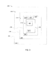
- Fig. 3 is a schematic block diagram of a protection system 200 for use with power system 100.
- Protection system 200 includes circuit protection device 122, a controller 202, and a plurality of sensors 204-210. Although a single circuit protection device 122 is illustrated in Fig. 3 , circuit protection system 200 may include any number of circuit protection devices 122.
- Sensors 204-210 generally directly or inferentially detect a level of danger from switchgear unit 106 to which a person, or body, may be exposed.
- the dangers to which the person may be exposed include, for example, electrical shock, fire hazard, pressure waves, excessive sound levels, etc.
- the level of danger to a person also referred to herein as a danger level, is generally directly related to the proximity of the person to the source of the danger, e.g. switchgear unit 106.
- Sensors 204-210 may detect the level of danger by detecting the proximity of a person, or body, (not shown) to circuit protection device 122 and switchgear unit 106 and/or by detecting a status of circuit protection device 122 and/or switchgear unit 106.
- sensor 204 detects whether a housing door (not shown) of switchgear unit 106 is open or closed. A person may be exposed to greater danger from switchgear unit 106 if the housing door is open than if the door were closed. In particular, some circuit protection devices, such as some arc containment devices, may not operate effectively if a housing door is open.
- Sensors 206 and 208 which may be referred to as a first sensor 206 and a second sensor 208, detect whether a person is located within a first zone 212 or a second zone 214. First zone 212 is associated with a first threshold 216 and second zone 214 is associated with a second threshold 218.
- First threshold 216 is a first threshold distance from switchgear unit 106
- second threshold 218 is a second threshold distance from switchgear unit 106.
- sensors 206 and 208 detect when a person crosses first threshold 216 and second threshold 218, respectively, in order to determine that a person has entered first zone 212 and/or second zone 214.
- sensors 206 and 208 may be motion detectors or proximity sensors configured to detect the presence of a person within first zone 212 and second zone 214.
- sensor 210 is configured to detect whether a person has entered a third zone 220.
- sensor 210 is coupled to a door of a room housing switchgear unit 106 and configured to detect when a person enters the room and third zone 220.
- Sensor 210 may be, for example, a laser sensor detecting when a person crosses a threshold 222 to enter the room and third zone 220.
- sensor 210 may be a door sensor configured to detect when the door to the room housing switchgear unit 106 is opened.
- protection system 200 may include more or fewer sensors and correspondingly more or fewer zones and/or thresholds.
- protection system 200 may include a single type of sensor, or multiple types of sensors.
- Sensors 204-210 may be any type of sensor suitable for detecting the proximity of a person to circuit protection device 122 and switchgear unit 106.
- sensors 204-210 may include motion sensors, laser sensors, door sensors, proximity sensors, etc.
- Zones 212, 214, and 220 associated with and/or defined in relation to sensors 204-210, generally indicate increasing levels of danger to which a person may be exposed. Outside the room in which switchgear unit 106 is located, a person is farthest from switchgear unit 106 and, accordingly, exposed to the least danger from switchgear unit 106. In third zone 220, a person is located closer to switchgear unit 106 than when outside the room, but still relatively far away from switchgear unit 106. In the second zone 214, the person is closer to switchgear unit 106 and, thus, the potential danger level for the person is increased over the third zone. Within first zone 212, the person is closest to switchgear unit 106 and is exposed to the greatest potential danger levels.
- thresholds 216, 218, and 222 and zones 212, 214, and 220 are defined in some embodiments in accordance with one or more safety agency codes, regulations, and/or standards.
- thresholds and zones are defined in accordance with approach boundaries as defined by the National Fire Prevention Association.
- first zone 212 is a prohibited zone in which a person must use the same personal protective equipment that would be used if direct contact with live wires were planned
- second zone 214 is a restricted approach zone in which only qualified personnel are permitted with appropriate protection
- third zone 220 is a limited approach zone in which unqualified personnel may only enter with a qualified supervisor or escort.
- zones 212, 214, and 220 may be other types of zones with other limitations and definitions.
- one or more of zones 212, 214, and 220 may additionally or alternatively be defined by the type of danger or injury that may be experienced in each zone.
- zones 212 and 214 may be zones in which a person is likely to experience second degree or greater bums upon occurrence of an arc flash in switchgear unit 106.
- Controller 202 is communicatively coupled to sensors 204-210.
- controller 202 is also communicatively coupled to central controller 108 and processors 128. Communication between controller 202, processors 128, and central controller 108 may be provided through a hardwired communication link or through a wireless communication link.
- Controller 224 monitors sensors 204-210 to determine a proximity of a person to switchgear unit 106 and/or a level of danger to which the person may be exposed. Moreover, controller 224 is configured to selectively enable circuit protection device 122.
- controller 202 is a digital controller including a processor and a memory device (neither shown).
- the memory device contains instructions that, when executed by the processor, cause the processor, and thereby controller 202, to perform as described herein.
- controller 202 is an analog controller.
- controller 202 is separate from other controllers, such as central controller 108.
- central controller 108 and/or processors 128 may perform the functions assigned to controller 202.
- Sensors 204-210 may be communicatively coupled to controller 202 independent of one another (e.g., each connected to a separate input of controller 202, coupled to controller 202 via a multiplexer, etc.), or may be coupled to controller 202 in parallel.
- Figs. 4 and 5 are schematic block diagrams showing parallel connection of sensors 206 and 207 to controller 202.
- An interposing relay 224 is coupled between sensors 206 and 207 and controller 202 to reduce noise sensitivity and to allow for paralleled inputs.
- sensors 208 and 210 are coupled to controller independent of each other and independent of sensors 206 and 207. In the embodiments of both of Figs.
- sensors 206 and 207 are coupled to controller 202 in parallel via interposing relay 224. Electrical power for operation of sensors 206 and 207 is provided by a power source 226. Sensors 206 and 207 are both associated with zone 212 and are configured to detect a body in zone 212. The signals from sensors 206 and 207 may be used by controller 202 in any suitable manner as described herein. Moreover, by using two sensors for a single zone, accuracy may be improved by decreasing false detections and/or the robustness and reliability of the system may be increased. For example, in Fig.
- signals from sensors 206 and 207 are subjected to an "AND" operation by AND gate 228, requiring both sensors 206 and 207 to detect a body in zone 212 before controller 202 will determine that a body is present in zone 212 and perform as described herein. Thus, nuisance activations, i.e. false alarms, may be reduced.
- sensors 206 and 207 are subjected to an "OR" operation.
- controller 202 determines a body is present in zone 212 if either sensor 206 or sensor 207 detects a body in zone 212. This configuration may continue to provide protection for a person even if one of the parallel connected sensors 206 and 207 were to fail or malfunction.
- Sensors 206 and 207 may additionally or alternatively be coupled to interposing relay 224 via an OR gate in a configuration similar to that shown in Fig. 5 (in which AND gate 228 would be an OR gate).
- two or more of sensors 204-210 may be connected separately to controller 202, whether via interposing relays or not, and controller may, via appropriate programming, subject the received signals to logical operations as described above.
- any suitable number of sensors may be connected to controller 202 in parallel.
- parallel connected sensors may be used in different ways and or in different combinations. For example, signals from sensors 206 and 207 may be combined in a logical AND operation when sensor 204 indicates the door of switchgear unit 106 is closed and combined with an OR operation if sensor 204 indicates the door of switchgear unit 106 is open.
- controller 202 is configured, such as via instructions stored in a memory device, to control circuit protection device 122 based at least in part on input from sensors 204-210.
- controller 202 enables and/or increases the protection provided by circuit protection device 122 as a person gets closer to switchgear unit 106.
- controller 202 is configured to disable and/or decrease the protection provided by circuit protection device 122 as the distance between a person and switchgear unit 106 increases.
- protection provided by circuit protection device 122 may be, additionally or alternatively, disabled and/or decreased manually by a person.
- controller 202 is configured to prohibit a person from manually disabling and/or decreasing the protection when a body is detected in one or more of zones 212, 214, and 220.
- enabling protection or "enabling" a circuit protection device refers to energizing, turning-on, and/or activating a de-energized, turned-off, and/or inactive circuit protection device.
- controller 202 may maintain circuit protection device 122 in an off state or in a minimal protection state.
- the level of protection provided by protection device 122 is increased by controller 202.
- the increased protection may be accomplished by enabling, or switching on, one or more protection device (e.g., an arc containment device) that is currently switched off, and/or enabling reduced energy let through (RELT) protection.
- "enabling" a circuit protection device includes enabling a different protection level of a circuit protection device.
- the increased protection may be accomplished by decreasing the trip threshold in a circuit breaker (i.e., enabling a different protection scheme or threshold in the circuit breaker).
- enabling a circuit protection device generally does not include activating the actual protection provided by the circuit protection device.
- controller 202 may enable an arc containment device by turning the device on, at which time the arc containment device monitors and prepares to protect against an electrical arc. Except in device testing situations, the arc containment device does not engage its protection until and unless the arc containment device detects an electrical arc.
- Controller 202 provides a dynamic information display to a person via display device 224, which is communicatively coupled to controller 202.
- Display device 224 may include, without limitation, a monitor, a television display, a plasma display, a liquid crystal display (LCD), a display based on light emitting diodes (LED), a display based on a plurality of organic light-emitting diodes (OLEDs), a display based on polymer light-emitting diodes (PLEDs), a display based on a plurality of surface-conduction electron-emitters (SEDs), a display including a projected and/or reflected image or any other suitable electronic device or display mechanism.
- LCD liquid crystal display
- LED light emitting diodes
- OLEDs organic light-emitting diodes
- PLEDs polymer light-emitting diodes
- SEDs surface-conduction electron-emitters
- Controller 202 is configured to cause display device 224 to display information related to the state of protection device 122 and/or the potential level of danger to which the person may currently be exposed. Accordingly, when there are no persons within zones 212, 214, or 220, controller 202 may cause display device 224 to indicate that protection is currently disabled. As a person enters zones 220, 214, and 212, controller updates the display on display device 224 to indicate the level of protection enabled (e.g., arc containment device enabled, circuit breaker thresholds decreased, RELT engaged, etc.). Moreover, in the exemplary embodiment controller 202 causes warning, hazard, and/or instructional information to be displayed on display device 224.
- level of protection enabled e.g., arc containment device enabled, circuit breaker thresholds decreased, RELT engaged, etc.
- controller 202 causes display device 224 to display first information in response to detecting a body in a first zone, such as zone 214, and to display second information in response to detecting a body in a second zone, such as zone 212.
- controller 202 presents, via display device 224, supervision, certification, and/or protective gear information on display device 224 as a function of the location of a body.
- the required level of supervision/certification required may be displayed when a body is detected in zone 214.
- controller 202 causes display device 224 to display a warning to the person that protective clothing is required.
- protection system 200 includes one or more devices for presenting information to a person in addition to, or alternative to, display device 224.
- system 200 may include a loudspeaker.
- Controller may provide audible status and warnings to a person similar to those displayed on display device 202.
- the audible status and/or warnings may include detailed information, such as a verbal reproduction of the text displayed on display device 224, or may include non-verbal sounds, such as alarm sounds, to indicate that a danger level has increased and/or to draw the person's attention to the display device 224.
- the additional devices may include other visual indicators, such as flashing lights.
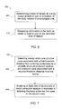
- Fig. 6 is a flowchart of an exemplary method 300 for use with a protection system, such as protection system 200.
- Method 300 includes determining 302 a level of danger to a body based at least in part on a location of the body relative to a switchgear unit. The location of the body is detected via at least one sensor.
- a controller causes a display device to display 304 warning information to the body based at least in part on the detected level of danger.
- Method 300 is at least partially executed by a processor.
- a plurality of computer-executable instructions are embodied within a computer-readable medium. The instructions, when executed by the processor, cause the processor to execute the steps of method 300 and/or to function as described herein.
- Fig. 7 is a flowchart of an exemplary method 400 for use with a protection system, such as protection system 200.
- Method 400 includes detecting 402 a body within one of a first zone associated with a first threshold distance from a device protectable by a plurality of circuit protection devices and a second zone associated with a second threshold distance from the device. The detection of the body within the first zone or the second zone is detected via at least one sensor.
- a controller enables 404 at least one of the plurality of circuit protection devices in response to detecting the body within the first zone or the second zone.
- Method 400 is at least partially executed by a processor.
- a plurality of computer-executable instructions are embodied within a computer-readable medium. The instructions, when executed by the processor, cause the processor to execute the steps of method 400 and/or to function as described herein.
- a technical effect of the method, device, and system described herein may include one or more of: (a) determining a level of danger to a body based at least in part on a location of the body relative to a switchgear unit; and (b) displaying warning information to the body based at least in part on the detected level of danger.
- Exemplary embodiments of a method, device, and system protection system activation and dynamic labeling are described above in detail.
- the method, device, and system are not limited to the specific embodiments described herein but, rather, operations of the method and/or components of the system and/or device may be utilized independently and separately from other operations and/or components described herein. Further, the described operations and/or components may also be defined in, or used in combination with, other systems, methods, and/or devices, and are not limited to practice with only the system, method, and device as described herein.
- circuit protection system described in connection with an exemplary circuit protection system
- embodiments of the invention are operational with numerous other circuit protection systems, or other systems or devices.
- the circuit protection system described herein is not intended to suggest any limitation as to the scope of use or functionality of any aspect of the invention.
- circuit protection system described herein should not be interpreted as having any dependency or requirement relating to any one or combination of components illustrated in the exemplary operating environment.
Landscapes
- Business, Economics & Management (AREA)
- Emergency Management (AREA)
- Physics & Mathematics (AREA)
- General Physics & Mathematics (AREA)
- Alarm Systems (AREA)
- Emergency Alarm Devices (AREA)
- Train Traffic Observation, Control, And Security (AREA)
- Radar Systems Or Details Thereof (AREA)
- Length Measuring Devices With Unspecified Measuring Means (AREA)
- Remote Monitoring And Control Of Power-Distribution Networks (AREA)
Abstract
Description
- The embodiments described herein relate generally to protection systems and, more particularly, to methods, systems, and apparatus for enabling one or more protection systems and providing dynamic labeling.
- Known electric power circuits and switchgear generally have conductors that are separated by insulation, such as air, or gas or solid dielectrics. However, if the conductors are positioned too closely together, or if a voltage between the conductors exceeds the insulative properties of the insulation between the conductors, an arc can occur. The insulation between the conductors can become ionized, which makes the insulation conductive and enables arc formation.
- An arc flash is caused by a rapid release of energy due to a fault between two phase conductors, between a phase conductor and a neutral conductor, or between a phase conductor and a ground point. Arc flash temperatures can reach or exceed 20,000°C, which can vaporize the conductors and adjacent equipment. In addition, an arc flash can release significant energy in the form of heat, intense light, pressure waves, and/or sound waves, sufficient to damage the conductors and adjacent equipment. Moreover, the released energy can cause significant injuries to humans in the vicinity of an arc fault event.
- Although devices for detecting and mitigating arc fault events exist and agencies and standards exist to regulate arc flash issues by mandating the use of personal protective clothing and equipment, human error may still permit exposure to potentially hazardous arc fault conditions. In particular, some known systems for mitigating arc fault issues require a human operator to engage the system. Because the arc fault mitigating system is often co-located in an enclosure with the gear that it is protecting, an operator must approach the enclosure in order to turn on the arc fault mitigation protection gear. Moreover, personal protective clothing only protects an operator if the operator is wearing the clothing. Accordingly, the operator needs to know when protective clothing should be worn.
- In one aspect, a protection system for use with a plurality of circuit protection devices coupled to a switchgear unit includes a first sensor for detecting a body located within a first zone associated with a threshold distance from the switchgear unit, and a controller coupled to the first sensor. The controller is configured to selectively enable the plurality of circuit protection devices. The controller is configured to enable a first circuit protection device of the plurality of circuit protection devices in response to detecting, via the first sensor, a body within the zone.
- In another aspect, a protection system includes a first sensor for detecting a body in a first zone associated with a first threshold distance from a switchgear unit, a second sensor for detecting a body in a second zone associated with a second threshold distance from the switchgear unit, a display device, and a controller coupled to the first sensor, the second sensor, and the display device. The controller is configured to cause the display device to display first information in response to detecting a body in the first zones and to display second information in response to detecting a body in the second zone.
- In another aspect, a method includes determining a level of danger to a body based at least in part on a location of the body relative to a switchgear unit, and displaying information to the body based at least in part on the detected level of danger.
-
Fig. 1 is a schematic block diagram of an exemplary power system. -
Fig. 2 is a schematic block diagram of an exemplary power distribution system that may be used with the power system shown inFig. 1 . -
Fig. 3 is a schematic block diagram of an exemplary protection system that may be used with the power system shown inFig. 1 . -
Fig. 4 is a schematic block diagram showing a parallel connection of two sensors of the exemplary protection system shown inFig. 3 . -
Fig. 5 is a schematic block diagram showing another parallel connection of two sensors of the exemplary protection system shown inFig. 3 . -
Fig. 6 is a flow diagram of an exemplary method for use with a protection system. -
Fig. 7 is a flow diagram of another exemplary method for use with a protection system. - Exemplary embodiments of a method, device, and system for protection system activation and dynamic labeling are described herein. These embodiments facilitate improving protection of persons from dangers arising from electrical equipment. The exemplary embodiments detect the proximity of a person to electrical equipment, such as switchgear, and automatically enable one or more protection devices as a function of the detected proximity of the person to the gear. Thus, protection devices are automatically enabled without a person needing to remember to enable the protection device. Moreover, in systems including more than one level of protection device, such as a system including a circuit breaker, an arc flash containment system, and a reduced energy let through (RELT) system, the level of protection can be varied as a function of the level of danger to the person as determined by the proximity of the person to the electrical equipment. Moreover, the exemplary embodiments provide dynamic labeling operable to display warning information to a person as a function of the level of danger to a person, determined, for example, by the proximity of the person to the electrical equipment. Thus, a person can be apprised of the level of danger to which the person is currently exposed, protective measures that should, or must, be taken, the status of protection devices, and/or rules/requirements/regulations applicable to the current level of danger to the person.
-
Fig. 1 is a schematic block diagram of anexemplary power system 100 that includes anequipment protection system 102 and adistribution system 104. In an exemplary embodiment,distribution system 104 includes a plurality ofswitchgear units 106.Protection system 102 includes acentral controller 108 that includes aprocessor 110 and amemory 112 coupled toprocessor 110.Processor 110 controls and/or monitors operation ofswitchgear units 106. More specifically,processor 110 controls and/or monitors operation of a plurality of circuit breakers and trip units (neither shown inFig. 1 ) withinswitchgear units 106.Processor 110 communicates withswitchgear units 106 through anetwork 114. For example,central controller 108 includes acentral communication unit 116 that enables transmitting and receiving data and/or commands betweenprocessor 110 andswitchgear units 106 throughnetwork 114. - It should be understood that the term "processor" refers generally to any programmable system including systems and microcontrollers, reduced instruction set circuits (RISC), application specific integrated circuits (ASIC), programmable logic circuits, and any other circuit or processor capable of executing the functions described herein. The above examples are exemplary only, and thus are not intended to limit in any way the definition and/or meaning of the term "processor."
- Memory 112 stores program code and instructions, executable by
processor 110, to control and/or monitorswitchgear units 106.Memory 112 may include, but is not limited to only include, non-volatile RAM (NVRAM), magnetic RAM (MRAM), ferroelectric RAM (FeRAM), read only memory (ROM), flash memory and/or Electrically Erasable Programmable Read Only Memory (EEPROM). Any other suitable magnetic, optical and/or semiconductor memory, by itself or in combination with other forms of memory, may be included inmemory 112.Memory 112 may also be, or include, a detachable or removable memory, including, but not limited to, a suitable cartridge, disk, CD ROM, DVD or USB memory. - In an exemplary embodiment,
protection system 102 includes adisplay device 118 and auser input device 120 that provide a user interface for monitoring and controllingdistribution system 104 usingprotection system 102.Display device 118 may include, without limitation, a monitor, a television display, a plasma display, a liquid crystal display (LCD), a display based on light emitting diodes (LED), a display based on a plurality of organic light-emitting diodes (OLEDs), a display based on polymer light-emitting diodes (PLEDs), a display based on a plurality of surface-conduction electron-emitters (SEDs), a display including a projected and/or reflected image or any other suitable electronic device or display mechanism. In one embodiment,display device 118 includes a touch-screen with an associated touch-screen controller.Display device 118 may be of any suitable configuration, such as a square, a rectangle or an elongated rectangle.User input device 120 includes, without limitation, a keyboard, a keypad, a touch-sensitive screen, a mouse, a scroll wheel, a pointing device, an audio input device employing speech-recognition software, and/or any suitable device that enables a user to input data intopower distribution system 104. -
Fig. 2 is a schematic block diagram ofpower distribution system 104 including a plurality ofcircuit protection devices 122. Eachcircuit protection device 122 is removably coupled withinswitchgear unit 106 and is configured to control power to one ormore loads 124. In an exemplary embodiment,circuit protection device 122 is an electronic trip unit (ETU) 122. -
Loads 124 may include, but are not limited to only including, machinery, motors, lighting, and/or other electrical and mechanical equipment of a manufacturing or power generation or distribution facility. Power is provided toswitchgear unit 106 from amain power feed 126, which is also coupled tocircuit protection device 122. The power is then divided into a plurality ofbranch circuits 127 usingcircuit protection devices 122 for providing power to loads 124. - Each
circuit protection device 122 includes aprocessor 128, as well as at least onesensor 130 and at least onetrip mechanism 132, such as one or more circuit breakers or arc containment devices coupled toprocessor 128. Exemplary circuit breakers include, for example, circuit switches and/or circuit interrupters that interrupt current flow through the circuit breaker to a load coupled to the circuit breaker. An exemplary arc containment device includes, for example, a containment assembly, a plurality of electrodes, a plasma gun, and a trigger circuit that causes the plasma gun to emit ablative plasma into a gap between the electrodes to divert energy into the containment assembly from an arc or other electrical fault that is detected on the circuit. -
Sensor 130 measures at least one operating condition oftrip mechanism 132 and/or ofcircuit protection device 122. In an exemplary embodiment,sensor 130 is atemperature sensor 130 that measures a temperature oftrip mechanism 132 and/orcircuit protection device 122, or of ambient air in close proximity totrip mechanism 132 and/orcircuit protection device 122. Alternatively,sensor 130 is ahumidity sensor 130 that measures a humidity or moisture content of ambient air surrounding, or in close proximity to,trip mechanism 132 and/orcircuit protection device 122 and/or a current sensor, such as a current transformer, a Rogowski coil, a Hall-effect sensor, and/or a shunt that measures a current flowing throughtrip mechanism 132 and/orcircuit protection device 122. In some embodiments,sensor 130 is avoltage sensor 130. Still alternatively,sensor 130 may include a combination of temperature, humidity, voltage, and/or current sensors and/or any other type of sensor that enablespower distribution system 104 to function as described herein. In an exemplary embodiment, eachsensor 130 generates data representative of the measured temperature (hereinafter referred to as "temperature data") and/or data representative of the measured humidity (hereinafter referred to as "humidity data") at, or in close proximity to, an associatedtrip mechanism 132. In addition, eachsensor 130 transmits a signal including, or representing, the temperature data and/or the humidity data to aprocessor 128 associated with, or coupled to,trip mechanism 132. Eachprocessor 128 is programmed to activatetrip mechanism 132 to interrupt a current provided to aload 124 if the temperature data, humidity data, and/or any other operating condition data exceeds a programmable trip threshold. - In an exemplary embodiment,
processors 128 are also communicatively coupled tocentral controller 108. For example,processors 128 may be directly coupled for communication withcentral controller 108, or may be coupled for communication withcentral controller 108 through acommunication unit 134. Communication betweenprocessors 128 andcentral controller 108 may also be provided through a hardwired communication link or through a wireless communication link.Processors 128 collect measured operating condition data relating to acorresponding trip mechanism 132. For example, eachprocessor 128 gathers measured operating condition data, such as measured temperature and/or humidity data, from asensor 130 associated with atrip mechanism 132 coupled toprocessor 128. In some embodiments,processor 128 periodically receives the measured operating condition data at a preselected frequency. For example,processor 128 receives temperature and/or humidity data at a frequency of about every minute, every hour, every day, or any other frequency.Processor 128 stores values representative of the temperature and/or humidity data in amemory 136 coupled toprocessor 128, and/or transmits the temperature and/or humidity data tocentral controller 108. In an alternative embodiment,circuit protection devices 122 do not includeprocessors 128, and the functionality ofprocessors 128 is incorporated intocentral controller 108. -
Memory 136 stores program code and instructions, executable byprocessor 128, to control and/or monitorcircuit protection device 122 and/ortrip mechanism 132. In an exemplary embodiment,memory 136 includes non-volatile RAM to enable data stored inmemory 136 to be retained after a power loss. Alternatively or additionally,memory 136 may include magnetic RAM (MRAM), ferroelectric RAM (FeRAM), read only memory (ROM), flash memory and/or Electrically Erasable Programmable Read Only Memory (EEPROM). Any other suitable magnetic, optical and/or semiconductor memory, by itself or in combination with other forms of memory, may be included inmemory 136.Memory 136 may also be, or include, a detachable or removable memory, including, but not limited to, a suitable cartridge, disk, CD ROM, DVD or USB memory. -
Circuit protection device 122 also includes adisplay device 138 coupled toprocessor 128. In an exemplary embodiment,display device 138 includes one or more light-emitting diodes (LEDs) that indicate a status ofcircuit protection device 122. For example,processor 128 may activate one or more components (e.g., LEDs) ofdisplay device 138 to indicate thatcurrent protection device 122 and/ortrip mechanism 132 is active and/or operating normally, that a fault or failure has occurred, that a useful life oftrip mechanism 132 or another component ofcircuit protection device 122 is below a threshold, and/or any other status oftrip mechanism 132 and/orcircuit protection device 122. - While
circuit protection device 122 has been described inFig. 2 with reference toswitchgear units 106 ofpower distribution system 104, it should be recognized thatcircuit protection device 122, or any components thereof, may be used with any device or system. Additionally or alternatively,sensor 130 andprocessor 128 may monitor or measure operating conditions, such as temperature and/or humidity, at, or in close proximity to, any other device or system other thantrip mechanism 132. -
Fig. 3 is a schematic block diagram of aprotection system 200 for use withpower system 100.Protection system 200 includescircuit protection device 122, acontroller 202, and a plurality of sensors 204-210. Although a singlecircuit protection device 122 is illustrated inFig. 3 ,circuit protection system 200 may include any number ofcircuit protection devices 122. - Sensors 204-210 generally directly or inferentially detect a level of danger from
switchgear unit 106 to which a person, or body, may be exposed. The dangers to which the person may be exposed include, for example, electrical shock, fire hazard, pressure waves, excessive sound levels, etc. The level of danger to a person, also referred to herein as a danger level, is generally directly related to the proximity of the person to the source of the danger,e.g. switchgear unit 106. Sensors 204-210 may detect the level of danger by detecting the proximity of a person, or body, (not shown) tocircuit protection device 122 andswitchgear unit 106 and/or by detecting a status ofcircuit protection device 122 and/orswitchgear unit 106. For example,sensor 204 detects whether a housing door (not shown) ofswitchgear unit 106 is open or closed. A person may be exposed to greater danger fromswitchgear unit 106 if the housing door is open than if the door were closed. In particular, some circuit protection devices, such as some arc containment devices, may not operate effectively if a housing door is open.Sensors first sensor 206 and asecond sensor 208, detect whether a person is located within afirst zone 212 or asecond zone 214.First zone 212 is associated with afirst threshold 216 andsecond zone 214 is associated with asecond threshold 218.First threshold 216 is a first threshold distance fromswitchgear unit 106, whilesecond threshold 218 is a second threshold distance fromswitchgear unit 106. In the exemplary embodiment,sensors first threshold 216 andsecond threshold 218, respectively, in order to determine that a person has enteredfirst zone 212 and/orsecond zone 214. In other embodiments,sensors first zone 212 andsecond zone 214. Similarly,sensor 210 is configured to detect whether a person has entered athird zone 220. In the exemplary embodiment,sensor 210 is coupled to a door of a roomhousing switchgear unit 106 and configured to detect when a person enters the room andthird zone 220.Sensor 210 may be, for example, a laser sensor detecting when a person crosses athreshold 222 to enter the room andthird zone 220. In other embodiments,sensor 210 may be a door sensor configured to detect when the door to the roomhousing switchgear unit 106 is opened. Although four sensors 204-210 are described in the exemplary embodiment,protection system 200 may include more or fewer sensors and correspondingly more or fewer zones and/or thresholds. Moreover,protection system 200 may include a single type of sensor, or multiple types of sensors. Sensors 204-210 may be any type of sensor suitable for detecting the proximity of a person tocircuit protection device 122 andswitchgear unit 106. For example, sensors 204-210 may include motion sensors, laser sensors, door sensors, proximity sensors, etc. -
Zones switchgear unit 106 is located, a person is farthest fromswitchgear unit 106 and, accordingly, exposed to the least danger fromswitchgear unit 106. Inthird zone 220, a person is located closer toswitchgear unit 106 than when outside the room, but still relatively far away fromswitchgear unit 106. In thesecond zone 214, the person is closer toswitchgear unit 106 and, thus, the potential danger level for the person is increased over the third zone. Withinfirst zone 212, the person is closest toswitchgear unit 106 and is exposed to the greatest potential danger levels. More specifically,thresholds zones first zone 212 is a prohibited zone in which a person must use the same personal protective equipment that would be used if direct contact with live wires were planned,second zone 214 is a restricted approach zone in which only qualified personnel are permitted with appropriate protection, andthird zone 220 is a limited approach zone in which unqualified personnel may only enter with a qualified supervisor or escort. In other embodiments,zones zones zones switchgear unit 106. -
Controller 202 is communicatively coupled to sensors 204-210. In an exemplary embodiment,controller 202 is also communicatively coupled tocentral controller 108 andprocessors 128. Communication betweencontroller 202,processors 128, andcentral controller 108 may be provided through a hardwired communication link or through a wireless communication link.Controller 224 monitors sensors 204-210 to determine a proximity of a person toswitchgear unit 106 and/or a level of danger to which the person may be exposed. Moreover,controller 224 is configured to selectively enablecircuit protection device 122. In the exemplary embodiment,controller 202 is a digital controller including a processor and a memory device (neither shown). The memory device contains instructions that, when executed by the processor, cause the processor, and therebycontroller 202, to perform as described herein. In other embodiments,controller 202 is an analog controller. In the exemplary embodiments,controller 202 is separate from other controllers, such ascentral controller 108. In other embodiments,central controller 108 and/orprocessors 128 may perform the functions assigned tocontroller 202. - Sensors 204-210 may be communicatively coupled to
controller 202 independent of one another (e.g., each connected to a separate input ofcontroller 202, coupled tocontroller 202 via a multiplexer, etc.), or may be coupled tocontroller 202 in parallel.Figs. 4 and 5 are schematic block diagrams showing parallel connection ofsensors controller 202. An interposingrelay 224 is coupled betweensensors controller 202 to reduce noise sensitivity and to allow for paralleled inputs. In the exemplary embodiment,sensors sensors Figs. 4 and 5 ,sensors controller 202 in parallel via interposingrelay 224. Electrical power for operation ofsensors power source 226.Sensors zone 212 and are configured to detect a body inzone 212. The signals fromsensors controller 202 in any suitable manner as described herein. Moreover, by using two sensors for a single zone, accuracy may be improved by decreasing false detections and/or the robustness and reliability of the system may be increased. For example, inFig. 5 , signals fromsensors gate 228, requiring bothsensors zone 212 beforecontroller 202 will determine that a body is present inzone 212 and perform as described herein. Thus, nuisance activations, i.e. false alarms, may be reduced. In the embodiment ofFig. 4 ,sensors controller 202 determines a body is present inzone 212 if eithersensor 206 orsensor 207 detects a body inzone 212. This configuration may continue to provide protection for a person even if one of the parallelconnected sensors Sensors relay 224 via an OR gate in a configuration similar to that shown inFig. 5 (in which ANDgate 228 would be an OR gate). In other embodiments, two or more of sensors 204-210 may be connected separately tocontroller 202, whether via interposing relays or not, and controller may, via appropriate programming, subject the received signals to logical operations as described above. Although described above with reference to only two sensors, any suitable number of sensors may be connected tocontroller 202 in parallel. Moreover, parallel connected sensors may be used in different ways and or in different combinations. For example, signals fromsensors sensor 204 indicates the door ofswitchgear unit 106 is closed and combined with an OR operation ifsensor 204 indicates the door ofswitchgear unit 106 is open. - With reference again to
Fig. 3 ,controller 202 is configured, such as via instructions stored in a memory device, to controlcircuit protection device 122 based at least in part on input from sensors 204-210. In particular,controller 202 enables and/or increases the protection provided bycircuit protection device 122 as a person gets closer toswitchgear unit 106. In some embodiments,controller 202 is configured to disable and/or decrease the protection provided bycircuit protection device 122 as the distance between a person andswitchgear unit 106 increases. In still other embodiments, protection provided bycircuit protection device 122 may be, additionally or alternatively, disabled and/or decreased manually by a person. Moreover, in some such embodiments,controller 202 is configured to prohibit a person from manually disabling and/or decreasing the protection when a body is detected in one or more ofzones zones controller 202 may maintaincircuit protection device 122 in an off state or in a minimal protection state. As a person crossesthresholds zones protection device 122 is increased bycontroller 202. The increased protection may be accomplished by enabling, or switching on, one or more protection device (e.g., an arc containment device) that is currently switched off, and/or enabling reduced energy let through (RELT) protection. Moreover, "enabling" a circuit protection device includes enabling a different protection level of a circuit protection device. Thus, the increased protection may be accomplished by decreasing the trip threshold in a circuit breaker (i.e., enabling a different protection scheme or threshold in the circuit breaker). Accordingly, as a person enters zones in which the person is potentially exposed to more danger, the level of protection for the person is automatically and progressively increased. As used herein, "enabling" a circuit protection device generally does not include activating the actual protection provided by the circuit protection device. For example,controller 202 may enable an arc containment device by turning the device on, at which time the arc containment device monitors and prepares to protect against an electrical arc. Except in device testing situations, the arc containment device does not engage its protection until and unless the arc containment device detects an electrical arc. -
Controller 202 provides a dynamic information display to a person viadisplay device 224, which is communicatively coupled tocontroller 202.Display device 224 may include, without limitation, a monitor, a television display, a plasma display, a liquid crystal display (LCD), a display based on light emitting diodes (LED), a display based on a plurality of organic light-emitting diodes (OLEDs), a display based on polymer light-emitting diodes (PLEDs), a display based on a plurality of surface-conduction electron-emitters (SEDs), a display including a projected and/or reflected image or any other suitable electronic device or display mechanism.Controller 202 is configured to causedisplay device 224 to display information related to the state ofprotection device 122 and/or the potential level of danger to which the person may currently be exposed. Accordingly, when there are no persons withinzones controller 202 may causedisplay device 224 to indicate that protection is currently disabled. As a person enterszones display device 224 to indicate the level of protection enabled (e.g., arc containment device enabled, circuit breaker thresholds decreased, RELT engaged, etc.). Moreover, in theexemplary embodiment controller 202 causes warning, hazard, and/or instructional information to be displayed ondisplay device 224. The information displayed on the display device is based at least in part on the location of a body relative toswitchgear unit 106. Thus,controller 202 causesdisplay device 224 to display first information in response to detecting a body in a first zone, such aszone 214, and to display second information in response to detecting a body in a second zone, such aszone 212. For example, in some embodiments,controller 202 presents, viadisplay device 224, supervision, certification, and/or protective gear information ondisplay device 224 as a function of the location of a body. Thus, the required level of supervision/certification required may be displayed when a body is detected inzone 214. When a body is detected inzone 212, in which protective equipment is required,controller 202 causesdisplay device 224 to display a warning to the person that protective clothing is required. - In some embodiments,
protection system 200 includes one or more devices for presenting information to a person in addition to, or alternative to,display device 224. For example,system 200 may include a loudspeaker. Controller may provide audible status and warnings to a person similar to those displayed ondisplay device 202. The audible status and/or warnings may include detailed information, such as a verbal reproduction of the text displayed ondisplay device 224, or may include non-verbal sounds, such as alarm sounds, to indicate that a danger level has increased and/or to draw the person's attention to thedisplay device 224. The additional devices may include other visual indicators, such as flashing lights. -
Fig. 6 is a flowchart of anexemplary method 300 for use with a protection system, such asprotection system 200.Method 300 includes determining 302 a level of danger to a body based at least in part on a location of the body relative to a switchgear unit. The location of the body is detected via at least one sensor. A controller causes a display device to display 304 warning information to the body based at least in part on the detected level of danger.Method 300 is at least partially executed by a processor. For example, a plurality of computer-executable instructions are embodied within a computer-readable medium. The instructions, when executed by the processor, cause the processor to execute the steps ofmethod 300 and/or to function as described herein. -
Fig. 7 is a flowchart of anexemplary method 400 for use with a protection system, such asprotection system 200.Method 400 includes detecting 402 a body within one of a first zone associated with a first threshold distance from a device protectable by a plurality of circuit protection devices and a second zone associated with a second threshold distance from the device. The detection of the body within the first zone or the second zone is detected via at least one sensor. A controller enables 404 at least one of the plurality of circuit protection devices in response to detecting the body within the first zone or the second zone.Method 400 is at least partially executed by a processor. For example, a plurality of computer-executable instructions are embodied within a computer-readable medium. The instructions, when executed by the processor, cause the processor to execute the steps ofmethod 400 and/or to function as described herein. - A technical effect of the method, device, and system described herein may include one or more of: (a) determining a level of danger to a body based at least in part on a location of the body relative to a switchgear unit; and (b) displaying warning information to the body based at least in part on the detected level of danger.
- Exemplary embodiments of a method, device, and system protection system activation and dynamic labeling are described above in detail. The method, device, and system are not limited to the specific embodiments described herein but, rather, operations of the method and/or components of the system and/or device may be utilized independently and separately from other operations and/or components described herein. Further, the described operations and/or components may also be defined in, or used in combination with, other systems, methods, and/or devices, and are not limited to practice with only the system, method, and device as described herein.
- Although the present invention is described in connection with an exemplary circuit protection system, embodiments of the invention are operational with numerous other circuit protection systems, or other systems or devices. The circuit protection system described herein is not intended to suggest any limitation as to the scope of use or functionality of any aspect of the invention. In addition, the circuit protection system described herein should not be interpreted as having any dependency or requirement relating to any one or combination of components illustrated in the exemplary operating environment.
- The order of execution or performance of the operations in the embodiments of the invention illustrated and described herein is not essential, unless otherwise specified. That is, the operations may be performed in any order, unless otherwise specified, and embodiments of the invention may include additional or fewer operations than those disclosed herein. For example, it is contemplated that executing or performing a particular operation before, contemporaneously with, or after another operation is within the scope of aspects of the invention.
- Although specific features of various embodiments of the invention may be shown in some drawings and not in others, this is for convenience only. In accordance with the principles of the invention, any feature of a drawing may be referenced and/or claimed in combination with any feature of any other drawing.
- This written description uses examples to disclose the invention, including the best mode, and also to enable any person skilled in the art to practice the invention, including making and using any devices or systems and performing any incorporated methods. The patentable scope of the invention is defined by the claims, and may include other examples that occur to those skilled in the art. Such other examples are intended to be within the scope of the claims if they have structural elements that do not differ from the literal language of the claims, or if they include equivalent structural elements with insubstantial differences from the literal language of the claims.
- Various aspects and embodiments of the present invention are defined by the following numbered clauses:
- 1. A protection system for use with a plurality of circuit protection devices coupled to a switchgear unit, said protection system comprising:
- a first sensor for detecting a body located within a first zone associated with a threshold distance from the switchgear unit; and
- a controller coupled to said first sensor, said controller configured to selectively enable the plurality of circuit protection devices, said controller configured to enable a first circuit protection device of the plurality of circuit protection devices in response to detecting, via said first sensor, a body within the first zone.
- 2. A protection system in accordance with
Clause 1, wherein said first sensor is a door sensor configured to detect when a door to the switchgear unit is opened. - 3. A protection system in accordance with
Clause 1 or Clause 2, wherein said first sensor is a door sensor configured to detect when a door to a room in which the switchgear unit is located is opened. - 4. A protection system in accordance with any preceding Clause, wherein said first sensor is a motion sensor configured to detect motion of a body within the first zone.
- 5. A protection system in accordance with any preceding Clause, wherein said first sensor is a laser sensor configured to detect when a body crosses the threshold distance from the switchgear unit.
- 6. A protection system in accordance with any preceding Clause, further comprising a second sensor for detecting a body within a second zone associated with a second threshold distance from the switchgear unit.
- 7. A protection system in accordance with any preceding Clause, wherein the controller is configured to enable a second circuit protection device of the plurality of different protection devices in response to detecting a body within the second zone.
- 8. A protection system in accordance with any preceding Clause, further comprising a sensor for detecting a body located within the first zone associated with a threshold distance from a switchgear unit, and an interposing relay, wherein said first sensor and said second sensor are coupled to said controller via said interposing relay.
- 9. A protection system in accordance with any preceding Clause, wherein said first sensor and said second sensor are coupled in parallel to said interposing relay.
- 10. A protection system in accordance with any preceding Clause, further comprising a logic gate, wherein said first sensor and said second sensor are coupled to said logic gate and said logic gate is coupled to said interposing relay.
- 11. A protection system comprising:
- a first sensor for detecting a body in a first zone associated with a first threshold distance from a switchgear unit;
- a second sensor for detecting a body in a second zone associated with a second threshold distance from the switchgear unit;
- a display device; and
- a controller coupled to said first sensor, said second sensor, and said display device, said controller configured to cause said display device to display a first information in response to detecting a body in the first zone and to display a second information in response to detecting a body in the second zone.
- 12. A protection system in accordance with any preceding Clause, wherein said first sensor is configured to detect a location of the body relative to the switchgear unit and the first information is based at least in part on the distance of the body from the switchgear unit.
- 13. A protection system in accordance with any preceding Clause, wherein the first sensor is configured to detect whether a door is in a first position or a second position and the first information is based at least in part on whether the door is in the first position or the second position.
- 14. A protection system in accordance with any preceding Clause, wherein said controller is coupled to a circuit protection device coupled to the switchgear unit and said controller is further configured to cause said display device to display a third information based at least in part on a status of the circuit protection device.
- 15. A protection system in accordance with any preceding Clause, wherein said controller is configured to enable the circuit protection device in response to detecting a body in one of the first zone and the second zone.
- 16. A method comprising:
- determining a level of danger to a body based at least in part on a location of the body relative to a switchgear unit; and
- displaying information to the body based at least in part on the detected level of danger.
- 17. A method in accordance with any preceding Clause, wherein determining a level of danger to a body comprises detecting the location of the body relative to the switchgear unit utilizing at least one sensor.
- 18. A method in accordance with any preceding Clause, further comprising enabling a circuit protection device coupled to the switchgear unit based at least in part on the location of the body relative to the switchgear unit.
- 19. A method in accordance with any preceding Clause, wherein determining a level of danger to a body comprises determining in which one of a plurality of zones relative to the switchgear unit the body is located, and wherein enabling a circuit protection device comprises enabling a different one of a plurality of types of protection devices of the circuit protection device based on the one of the plurality of zones in which the body is located.
- 20. A method in accordance with any preceding Clause, wherein determining a level of danger to a body comprises determining in which one of a plurality of zones relative to the switchgear unit the body is located, and wherein displaying warning information comprises displaying information relevant to the one of the plurality of zones in which the body is located.
- 21. A method comprising:
- detecting a body within one of a first zone associated with a first threshold distance from a device protectable by a plurality of circuit protection devices and a second zone associated with a second threshold distance from the device; and
- enabling at least one of the plurality of circuit protection devices in response to detecting the body within the first zone or the second zone.
Claims (15)
- A protection system (102) for use with a plurality of circuit protection devices coupled to a switchgear unit (106), said protection system comprising:a first sensor (204) for detecting a body located within a first zone associated with a threshold distance from the switchgear unit; anda controller (202) coupled to said first sensor, said controller configured to selectively enable the plurality of circuit protection devices, said controller configured to enable a first circuit protection device of the plurality of circuit protection devices in response to detecting, via said first sensor (204), a body within the first zone.
- A protection system in accordance with Claim 1, wherein said first sensor is a door sensor configured to detect when a door to the switchgear unit is opened.
- A protection system in accordance with Claim 1 or Claim 2, wherein said first sensor is a door sensor configured to detect when a door to a room in which the switchgear unit is located is opened.
- A protection system in accordance with any preceding Claim, wherein said first sensor is a motion sensor configured to detect motion of a body within the first zone.
- A protection system in accordance with any preceding Claim, wherein said first sensor is a laser sensor configured to detect when a body crosses the threshold distance from the switchgear unit.
- A protection system in accordance with any preceding Claim, further comprising a second sensor for detecting a body within a second zone associated with a second threshold distance from the switchgear unit.
- A protection system in accordance with any preceding Claim, wherein the controller is configured to enable a second circuit protection device of the plurality of different protection devices in response to detecting a body within the second zone.
- A protection system in accordance with any preceding Claim, further comprising a sensor for detecting a body located within the first zone associated with a threshold distance from a switchgear unit, and an interposing relay, wherein said first sensor and said second sensor are coupled to said controller via said interposing relay.
- A protection system in accordance with any preceding Claim, wherein said first sensor and said second sensor are coupled in parallel to said interposing relay.
- A protection system in accordance with any preceding Claim, further comprising a logic gate, wherein said first sensor and said second sensor are coupled to said logic gate and said logic gate is coupled to said interposing relay.
- A protection system comprising:a first sensor for detecting a body in a first zone associated with a first threshold distance from a switchgear unit;a second sensor for detecting a body in a second zone associated with a second threshold distance from the switchgear unit.a display device; anda controller coupled to said first sensor, said second sensor, and said display device, said controller configured to cause said display device to display a first information in response to detecting a body in the first zone and to display a second information in response to detecting a body in the second zone.
- A protection system in accordance with Claim 11, wherein said first sensor is configured to detect a location of the body relative to the switchgear unit and the first information is based at least in part on the distance of the body from the switchgear unit.
- A protection system in accordance with Claim 11 or Claim 12, wherein the first sensor is configured to detect whether a door is in a first position or a second position and the first information is based at least in part on whether the door is in the first position or the second position.
- A method comprising:determining a level of danger to a body based at least in part on a location of the body relative to a switchgear unit; anddisplaying information to the body based at least in part on the detected level of danger.
- A method comprising:detecting a body within one of a first zone associated with a first threshold distance from a device protectable by a plurality of circuit protection devices and a second zone associated with a second threshold distance from the device; andenabling at least one of the plurality of circuit protection devices in response to detecting the body within the first zone or the second zone.
Applications Claiming Priority (1)
| Application Number | Priority Date | Filing Date | Title |
|---|---|---|---|
| US13/466,248 US8981954B2 (en) | 2012-05-08 | 2012-05-08 | Methods, systems, and apparatus for protection system activation and dynamic labeling |
Publications (3)
| Publication Number | Publication Date |
|---|---|
| EP2662942A2 true EP2662942A2 (en) | 2013-11-13 |
| EP2662942A3 EP2662942A3 (en) | 2018-01-03 |
| EP2662942B1 EP2662942B1 (en) | 2022-03-30 |
Family
ID=48606996
Family Applications (1)
| Application Number | Title | Priority Date | Filing Date |
|---|---|---|---|
| EP13166358.5A Active EP2662942B1 (en) | 2012-05-08 | 2013-05-03 | Methods, systems, and apparatus for protection system activation and dynamic labeling |
Country Status (5)
| Country | Link |
|---|---|
| US (1) | US8981954B2 (en) |
| EP (1) | EP2662942B1 (en) |
| JP (1) | JP6194188B2 (en) |
| CN (1) | CN103390880B (en) |
| RU (1) | RU2634123C2 (en) |
Cited By (2)
| Publication number | Priority date | Publication date | Assignee | Title |
|---|---|---|---|---|
| WO2015126540A1 (en) * | 2014-02-18 | 2015-08-27 | Eaton Corporation | Meter or display device for calculation and display of arc flash incident energy |
| FR3017957A1 (en) * | 2014-02-21 | 2015-08-28 | Gen Electric | CURRENT AND VOLTAGE MODULE AND CURRENT MONITORING AND VOLTAGE MONITORING METHODS IN POWER DISTRIBUTION NETWORKS |
Families Citing this family (19)
| Publication number | Priority date | Publication date | Assignee | Title |
|---|---|---|---|---|
| US20130073257A1 (en) * | 2011-09-19 | 2013-03-21 | Craig Benjamin Williams | Method, device, and system for monitoring a component |
| US9804576B2 (en) * | 2013-02-27 | 2017-10-31 | Rockwell Automation Technologies, Inc. | Recognition-based industrial automation control with position and derivative decision reference |
| US9498885B2 (en) | 2013-02-27 | 2016-11-22 | Rockwell Automation Technologies, Inc. | Recognition-based industrial automation control with confidence-based decision support |
| US9393695B2 (en) | 2013-02-27 | 2016-07-19 | Rockwell Automation Technologies, Inc. | Recognition-based industrial automation control with person and object discrimination |
| US9798302B2 (en) | 2013-02-27 | 2017-10-24 | Rockwell Automation Technologies, Inc. | Recognition-based industrial automation control with redundant system input support |
| US9653918B2 (en) * | 2013-03-14 | 2017-05-16 | Eaton Corporation | Autonomous thermal event control and monitoring system for a network vault |
| KR101594333B1 (en) * | 2014-11-20 | 2016-02-16 | 정혜진 | Incoming and distribution panel having a alarm apparatus for preventing electric shock |
| US10373449B2 (en) * | 2016-01-19 | 2019-08-06 | The Boeing Company | System and method for protective eyewear |
| EP3469564B1 (en) | 2016-06-08 | 2022-04-13 | Siemens Healthcare Diagnostics Inc. | Apparatus, systems, and methods providing remote access warning |
| US10121363B2 (en) * | 2016-12-27 | 2018-11-06 | Lite-On Electronics (Guangzhou) Limited | Alarm triggering method for sensor and electronic device using the same |
| US10673226B2 (en) * | 2017-02-22 | 2020-06-02 | Abb Schweiz Ag | Power distribution systems and methods of operating power distribution systems with a communication network |
| US10797479B2 (en) | 2017-02-22 | 2020-10-06 | Abb Schweiz Ag | Power distribution systems and methods of performing ground fault detection in power distribution systems with a communication network |
| US20190114883A1 (en) * | 2017-10-12 | 2019-04-18 | Honeywell International Inc. | Systems and methods for providing a plurality of alarm levels for a motion detector monitoring a region |
| US11385006B2 (en) * | 2018-03-02 | 2022-07-12 | Ellen Marcie Emas | Firearm discharge prevention system and method |
| US10438464B1 (en) | 2018-06-06 | 2019-10-08 | Ademco Inc. | Systems and methods for determining and verifying a presence of an object or an intruder in a secured area |
| US11038335B2 (en) * | 2018-10-12 | 2021-06-15 | Avista Corporation | Systems and methods to detect and react to objects in proximity to power systems |
| US10996325B2 (en) | 2018-11-30 | 2021-05-04 | Ademco Inc. | Systems and methods for adjusting a signal broadcast pattern of an intrusion detector |
| US11074794B2 (en) | 2018-11-30 | 2021-07-27 | Ademco Inc. | Systems and methods for activating and deactivating controlled devices in a secured area |
| US10762773B1 (en) | 2019-08-19 | 2020-09-01 | Ademco Inc. | Systems and methods for building and using a false alarm predicting model to determine whether to alert a user and/or relevant authorities about an alarm signal from a security system |
Family Cites Families (18)
| Publication number | Priority date | Publication date | Assignee | Title |
|---|---|---|---|---|
| SU995191A1 (en) * | 1981-10-02 | 1983-02-07 | Азербайджанский Научно-Исследовательский Институт Энергетики Им.И.Г.Есьмана | Device for protecting personnel from hazardous aproach to overhead power transmission line wire |
| US4797568A (en) * | 1987-08-21 | 1989-01-10 | Gumbs Curtis M | Electronic switching system for controlling indoor and outdoor lights |
| USRE39081E1 (en) * | 1993-11-30 | 2006-05-02 | Alan E. Thomas | Localized automatic fire extinguishing apparatus |
| US20050264427A1 (en) * | 2000-03-03 | 2005-12-01 | The Gov. Of The Usa As Repres. By The Secretary Of The Dept. Of Health And Human Services | Electrical injury protection system |
| US7305108B2 (en) * | 2001-11-08 | 2007-12-04 | Pelco | Security identification system |
| AU2003217663A1 (en) * | 2002-02-25 | 2003-09-09 | General Electric Company | Method and system for conditionally triggered system data capture |
| US7292422B2 (en) | 2004-11-29 | 2007-11-06 | Siemens Energy & Automation, Inc. | Occupancy-based circuit breaker control |
| US20090309604A1 (en) * | 2005-05-06 | 2009-12-17 | Yongming Zhang | Electrostatic monitoring system |
| US8032260B2 (en) | 2005-11-30 | 2011-10-04 | General Electric Company | Method and system for controlling a power distribution system |
| US20110172840A1 (en) * | 2005-11-30 | 2011-07-14 | Radoslaw Narel | Centrally controlled protection system having reduced energy let-through mode |
| CA2653613A1 (en) | 2006-06-29 | 2008-01-03 | Edsa Micro Corporation | Systems and methods for providing real-time predictions of arc flash incident energy, arc flash protection boundary, and required personal protective equipment (ppe) levels to comply with workplace safety standards |
| US20080142486A1 (en) * | 2006-12-19 | 2008-06-19 | Nataniel Barbosa Vicente | Circuit breaker with adjustable arc-flash protection and wireless sensor and method of use |
| CN101478176B (en) * | 2008-01-03 | 2012-11-21 | 鸿富锦精密工业(深圳)有限公司 | Backup electric power system |
| BRPI0918899A2 (en) | 2008-09-19 | 2017-08-01 | Schweitzer Engineering Lab Inc | method for self-testing an electric arc detection device, self-testing electrical arc detection device, and computer readable storage medium |
| US8351171B2 (en) | 2008-10-14 | 2013-01-08 | Siemens Industry, Inc. | Integrated automatic selection of maintenance mode in electronic tripping systems to minimize arc fault energy |
| AT509253A1 (en) * | 2009-08-05 | 2011-07-15 | Moeller Gebaeudeautomation Gmbh | ELECTRICAL INSTALLATION ARRANGEMENT |
| US8493012B2 (en) * | 2009-11-17 | 2013-07-23 | Eaton Corporation | Protection relay, electrical switching apparatus, and system for determining and outputting fault current available at a load and incident energy or personal protective equipment level operatively associated therewith |
| US8649139B2 (en) * | 2010-08-23 | 2014-02-11 | General Electric Company | Methods, systems, and apparatus for detecting arc flash events using current and voltage |
-
2012
- 2012-05-08 US US13/466,248 patent/US8981954B2/en active Active
-
2013
- 2013-05-03 EP EP13166358.5A patent/EP2662942B1/en active Active
- 2013-05-06 RU RU2013120129A patent/RU2634123C2/en active
- 2013-05-07 JP JP2013097489A patent/JP6194188B2/en active Active
- 2013-05-08 CN CN201310166747.XA patent/CN103390880B/en active Active
Non-Patent Citations (1)
| Title |
|---|
| None |
Cited By (2)
| Publication number | Priority date | Publication date | Assignee | Title |
|---|---|---|---|---|
| WO2015126540A1 (en) * | 2014-02-18 | 2015-08-27 | Eaton Corporation | Meter or display device for calculation and display of arc flash incident energy |
| FR3017957A1 (en) * | 2014-02-21 | 2015-08-28 | Gen Electric | CURRENT AND VOLTAGE MODULE AND CURRENT MONITORING AND VOLTAGE MONITORING METHODS IN POWER DISTRIBUTION NETWORKS |
Also Published As
| Publication number | Publication date |
|---|---|
| JP6194188B2 (en) | 2017-09-06 |
| CN103390880B (en) | 2018-11-02 |
| US8981954B2 (en) | 2015-03-17 |
| RU2013120129A (en) | 2014-11-20 |
| EP2662942A3 (en) | 2018-01-03 |
| RU2634123C2 (en) | 2017-10-24 |
| EP2662942B1 (en) | 2022-03-30 |
| JP2013236538A (en) | 2013-11-21 |
| US20130300566A1 (en) | 2013-11-14 |
| CN103390880A (en) | 2013-11-13 |
Similar Documents
| Publication | Publication Date | Title |
|---|---|---|
| EP2662942B1 (en) | Methods, systems, and apparatus for protection system activation and dynamic labeling | |
| JP5923254B2 (en) | System and apparatus for detecting arc flash events using current and voltage | |
| US8564915B2 (en) | Methods, systems, and apparatus for detecting arc flash events using light and time discrimination | |
| JP5795247B2 (en) | Electrical equipment fire suppression device | |
| US8964344B2 (en) | Circuit breaker signaling system for control of an arc fault detection system | |
| US8575916B2 (en) | Method, system, and apparatus for detecting an arc event using breaker status | |
| US20140192458A1 (en) | Power distribution systems and methods of operating a power distribution system including arc flash detection | |
| CN105576619B (en) | Circuit protection device and method for monitoring protection device in power distribution system | |
| US20110128005A1 (en) | Sluggish circuit breaker detection system and method | |
| US9325167B2 (en) | Method, system, and apparatus for providing arc flash mitigation | |
| US8649146B2 (en) | Capacitance check and current monitoring circuit for use with a circuit protection device | |
| EP2573577A2 (en) | Method, device, and system for monitoring a component | |
| US9214797B2 (en) | Apparatus, systems, and methods for operation of a trip unit in a circuit protection device | |
| EP1971007A1 (en) | System and method for fault protection in compact secondary substations | |
| KR101389844B1 (en) | Degradation diagnosis and protection relay system with multi-sensor | |
| KR102641136B1 (en) | Power quality improvement and electrical accident detection device | |
| US4223306A (en) | Device for detection of short circuits in industrial uses | |
| KR20150128123A (en) | Digital protecting relay capable of monitoring transformer | |
| KR20150089775A (en) | Electronic relay | |
| CN115424409A (en) | Comprehensive multifunctional anti-electric-shock safety protection device | |
| KR200298557Y1 (en) | System for Screening Oil Filter | |
| KR20220131787A (en) | Smart switchboard for preventing electrical accidents | |
| KR20100002072U (en) | Current display device and current breaker having the same |
Legal Events
| Date | Code | Title | Description |
|---|---|---|---|
| PUAI | Public reference made under article 153(3) epc to a published international application that has entered the european phase |
Free format text: ORIGINAL CODE: 0009012 |
|
| AK | Designated contracting states |
Kind code of ref document: A2 Designated state(s): AL AT BE BG CH CY CZ DE DK EE ES FI FR GB GR HR HU IE IS IT LI LT LU LV MC MK MT NL NO PL PT RO RS SE SI SK SM TR |
|
| AX | Request for extension of the european patent |
Extension state: BA ME |
|
| RIC1 | Information provided on ipc code assigned before grant |
Ipc: G08B 21/02 20060101ALI20170619BHEP Ipc: H02H 5/12 20060101AFI20170619BHEP |
|
| PUAL | Search report despatched |
Free format text: ORIGINAL CODE: 0009013 |
|
| AK | Designated contracting states |
Kind code of ref document: A3 Designated state(s): AL AT BE BG CH CY CZ DE DK EE ES FI FR GB GR HR HU IE IS IT LI LT LU LV MC MK MT NL NO PL PT RO RS SE SI SK SM TR |
|
| AX | Request for extension of the european patent |
Extension state: BA ME |
|
| RIC1 | Information provided on ipc code assigned before grant |
Ipc: G08B 21/02 20060101ALI20171128BHEP Ipc: H02H 5/12 20060101AFI20171128BHEP |
|
| STAA | Information on the status of an ep patent application or granted ep patent |
Free format text: STATUS: REQUEST FOR EXAMINATION WAS MADE |
|
| 17P | Request for examination filed |
Effective date: 20180703 |
|
| RBV | Designated contracting states (corrected) |
Designated state(s): AL AT BE BG CH CY CZ DE DK EE ES FI FR GB GR HR HU IE IS IT LI LT LU LV MC MK MT NL NO PL PT RO RS SE SI SK SM TR |
|
| RAP1 | Party data changed (applicant data changed or rights of an application transferred) |
Owner name: ABB SCHWEIZ AG |
|
| STAA | Information on the status of an ep patent application or granted ep patent |
Free format text: STATUS: EXAMINATION IS IN PROGRESS |
|
| 17Q | First examination report despatched |
Effective date: 20200210 |
|
| RAP3 | Party data changed (applicant data changed or rights of an application transferred) |
Owner name: ABB SCHWEIZ AG |
|
| GRAP | Despatch of communication of intention to grant a patent |
Free format text: ORIGINAL CODE: EPIDOSNIGR1 |
|
| STAA | Information on the status of an ep patent application or granted ep patent |
Free format text: STATUS: GRANT OF PATENT IS INTENDED |
|
| INTG | Intention to grant announced |
Effective date: 20211025 |
|
| GRAS | Grant fee paid |
Free format text: ORIGINAL CODE: EPIDOSNIGR3 |
|
| GRAA | (expected) grant |
Free format text: ORIGINAL CODE: 0009210 |
|
| STAA | Information on the status of an ep patent application or granted ep patent |
Free format text: STATUS: THE PATENT HAS BEEN GRANTED |
|
| AK | Designated contracting states |
Kind code of ref document: B1 Designated state(s): AL AT BE BG CH CY CZ DE DK EE ES FI FR GB GR HR HU IE IS IT LI LT LU LV MC MK MT NL NO PL PT RO RS SE SI SK SM TR |
|
| REG | Reference to a national code |
Ref country code: GB Ref legal event code: FG4D |
|
| REG | Reference to a national code |
Ref country code: CH Ref legal event code: EP |
|
| REG | Reference to a national code |
Ref country code: DE Ref legal event code: R096 Ref document number: 602013081240 Country of ref document: DE |
|
| REG | Reference to a national code |
Ref country code: AT Ref legal event code: REF Ref document number: 1480063 Country of ref document: AT Kind code of ref document: T Effective date: 20220415 |
|
| REG | Reference to a national code |
Ref country code: IE Ref legal event code: FG4D |
|
| REG | Reference to a national code |
Ref country code: LT Ref legal event code: MG9D |
|
| PG25 | Lapsed in a contracting state [announced via postgrant information from national office to epo] |
Ref country code: SE Free format text: LAPSE BECAUSE OF FAILURE TO SUBMIT A TRANSLATION OF THE DESCRIPTION OR TO PAY THE FEE WITHIN THE PRESCRIBED TIME-LIMIT Effective date: 20220330 Ref country code: RS Free format text: LAPSE BECAUSE OF FAILURE TO SUBMIT A TRANSLATION OF THE DESCRIPTION OR TO PAY THE FEE WITHIN THE PRESCRIBED TIME-LIMIT Effective date: 20220330 Ref country code: NO Free format text: LAPSE BECAUSE OF FAILURE TO SUBMIT A TRANSLATION OF THE DESCRIPTION OR TO PAY THE FEE WITHIN THE PRESCRIBED TIME-LIMIT Effective date: 20220630 Ref country code: LT Free format text: LAPSE BECAUSE OF FAILURE TO SUBMIT A TRANSLATION OF THE DESCRIPTION OR TO PAY THE FEE WITHIN THE PRESCRIBED TIME-LIMIT Effective date: 20220330 Ref country code: HR Free format text: LAPSE BECAUSE OF FAILURE TO SUBMIT A TRANSLATION OF THE DESCRIPTION OR TO PAY THE FEE WITHIN THE PRESCRIBED TIME-LIMIT Effective date: 20220330 Ref country code: BG Free format text: LAPSE BECAUSE OF FAILURE TO SUBMIT A TRANSLATION OF THE DESCRIPTION OR TO PAY THE FEE WITHIN THE PRESCRIBED TIME-LIMIT Effective date: 20220630 |
|
| REG | Reference to a national code |
Ref country code: NL Ref legal event code: MP Effective date: 20220330 |
|
| REG | Reference to a national code |
Ref country code: AT Ref legal event code: MK05 Ref document number: 1480063 Country of ref document: AT Kind code of ref document: T Effective date: 20220330 |
|
| PG25 | Lapsed in a contracting state [announced via postgrant information from national office to epo] |
Ref country code: LV Free format text: LAPSE BECAUSE OF FAILURE TO SUBMIT A TRANSLATION OF THE DESCRIPTION OR TO PAY THE FEE WITHIN THE PRESCRIBED TIME-LIMIT Effective date: 20220330 Ref country code: GR Free format text: LAPSE BECAUSE OF FAILURE TO SUBMIT A TRANSLATION OF THE DESCRIPTION OR TO PAY THE FEE WITHIN THE PRESCRIBED TIME-LIMIT Effective date: 20220701 Ref country code: FI Free format text: LAPSE BECAUSE OF FAILURE TO SUBMIT A TRANSLATION OF THE DESCRIPTION OR TO PAY THE FEE WITHIN THE PRESCRIBED TIME-LIMIT Effective date: 20220330 |
|
| PG25 | Lapsed in a contracting state [announced via postgrant information from national office to epo] |
Ref country code: NL Free format text: LAPSE BECAUSE OF FAILURE TO SUBMIT A TRANSLATION OF THE DESCRIPTION OR TO PAY THE FEE WITHIN THE PRESCRIBED TIME-LIMIT Effective date: 20220330 |
|
| PG25 | Lapsed in a contracting state [announced via postgrant information from national office to epo] |
Ref country code: SM Free format text: LAPSE BECAUSE OF FAILURE TO SUBMIT A TRANSLATION OF THE DESCRIPTION OR TO PAY THE FEE WITHIN THE PRESCRIBED TIME-LIMIT Effective date: 20220330 Ref country code: RO Free format text: LAPSE BECAUSE OF FAILURE TO SUBMIT A TRANSLATION OF THE DESCRIPTION OR TO PAY THE FEE WITHIN THE PRESCRIBED TIME-LIMIT Effective date: 20220330 Ref country code: PT Free format text: LAPSE BECAUSE OF FAILURE TO SUBMIT A TRANSLATION OF THE DESCRIPTION OR TO PAY THE FEE WITHIN THE PRESCRIBED TIME-LIMIT Effective date: 20220801 Ref country code: ES Free format text: LAPSE BECAUSE OF FAILURE TO SUBMIT A TRANSLATION OF THE DESCRIPTION OR TO PAY THE FEE WITHIN THE PRESCRIBED TIME-LIMIT Effective date: 20220330 Ref country code: EE Free format text: LAPSE BECAUSE OF FAILURE TO SUBMIT A TRANSLATION OF THE DESCRIPTION OR TO PAY THE FEE WITHIN THE PRESCRIBED TIME-LIMIT Effective date: 20220330 Ref country code: CZ Free format text: LAPSE BECAUSE OF FAILURE TO SUBMIT A TRANSLATION OF THE DESCRIPTION OR TO PAY THE FEE WITHIN THE PRESCRIBED TIME-LIMIT Effective date: 20220330 Ref country code: AT Free format text: LAPSE BECAUSE OF FAILURE TO SUBMIT A TRANSLATION OF THE DESCRIPTION OR TO PAY THE FEE WITHIN THE PRESCRIBED TIME-LIMIT Effective date: 20220330 |
|
| PG25 | Lapsed in a contracting state [announced via postgrant information from national office to epo] |
Ref country code: PL Free format text: LAPSE BECAUSE OF FAILURE TO SUBMIT A TRANSLATION OF THE DESCRIPTION OR TO PAY THE FEE WITHIN THE PRESCRIBED TIME-LIMIT Effective date: 20220330 Ref country code: IS Free format text: LAPSE BECAUSE OF FAILURE TO SUBMIT A TRANSLATION OF THE DESCRIPTION OR TO PAY THE FEE WITHIN THE PRESCRIBED TIME-LIMIT Effective date: 20220730 Ref country code: AL Free format text: LAPSE BECAUSE OF FAILURE TO SUBMIT A TRANSLATION OF THE DESCRIPTION OR TO PAY THE FEE WITHIN THE PRESCRIBED TIME-LIMIT Effective date: 20220330 |
|
| REG | Reference to a national code |
Ref country code: CH Ref legal event code: PL |
|
| REG | Reference to a national code |
Ref country code: DE Ref legal event code: R097 Ref document number: 602013081240 Country of ref document: DE |
|
| REG | Reference to a national code |
Ref country code: BE Ref legal event code: MM Effective date: 20220531 |
|
| PG25 | Lapsed in a contracting state [announced via postgrant information from national office to epo] |
Ref country code: MC Free format text: LAPSE BECAUSE OF FAILURE TO SUBMIT A TRANSLATION OF THE DESCRIPTION OR TO PAY THE FEE WITHIN THE PRESCRIBED TIME-LIMIT Effective date: 20220330 Ref country code: LU Free format text: LAPSE BECAUSE OF NON-PAYMENT OF DUE FEES Effective date: 20220503 Ref country code: LI Free format text: LAPSE BECAUSE OF NON-PAYMENT OF DUE FEES Effective date: 20220531 Ref country code: DK Free format text: LAPSE BECAUSE OF FAILURE TO SUBMIT A TRANSLATION OF THE DESCRIPTION OR TO PAY THE FEE WITHIN THE PRESCRIBED TIME-LIMIT Effective date: 20220330 Ref country code: CH Free format text: LAPSE BECAUSE OF NON-PAYMENT OF DUE FEES Effective date: 20220531 |
|
| PLBE | No opposition filed within time limit |
Free format text: ORIGINAL CODE: 0009261 |
|
| STAA | Information on the status of an ep patent application or granted ep patent |
Free format text: STATUS: NO OPPOSITION FILED WITHIN TIME LIMIT |
|
| GBPC | Gb: european patent ceased through non-payment of renewal fee |
Effective date: 20220630 |
|
| 26N | No opposition filed |
Effective date: 20230103 |
|
| PG25 | Lapsed in a contracting state [announced via postgrant information from national office to epo] |
Ref country code: IE Free format text: LAPSE BECAUSE OF NON-PAYMENT OF DUE FEES Effective date: 20220503 |
|
| PG25 | Lapsed in a contracting state [announced via postgrant information from national office to epo] |
Ref country code: SI Free format text: LAPSE BECAUSE OF FAILURE TO SUBMIT A TRANSLATION OF THE DESCRIPTION OR TO PAY THE FEE WITHIN THE PRESCRIBED TIME-LIMIT Effective date: 20220330 Ref country code: GB Free format text: LAPSE BECAUSE OF NON-PAYMENT OF DUE FEES Effective date: 20220630 Ref country code: BE Free format text: LAPSE BECAUSE OF NON-PAYMENT OF DUE FEES Effective date: 20220531 |
|
| PG25 | Lapsed in a contracting state [announced via postgrant information from national office to epo] |
Ref country code: IT Free format text: LAPSE BECAUSE OF FAILURE TO SUBMIT A TRANSLATION OF THE DESCRIPTION OR TO PAY THE FEE WITHIN THE PRESCRIBED TIME-LIMIT Effective date: 20220330 |
|
| PG25 | Lapsed in a contracting state [announced via postgrant information from national office to epo] |
Ref country code: HU Free format text: LAPSE BECAUSE OF FAILURE TO SUBMIT A TRANSLATION OF THE DESCRIPTION OR TO PAY THE FEE WITHIN THE PRESCRIBED TIME-LIMIT; INVALID AB INITIO Effective date: 20130503 |
|
| PG25 | Lapsed in a contracting state [announced via postgrant information from national office to epo] |
Ref country code: MK Free format text: LAPSE BECAUSE OF FAILURE TO SUBMIT A TRANSLATION OF THE DESCRIPTION OR TO PAY THE FEE WITHIN THE PRESCRIBED TIME-LIMIT Effective date: 20220330 Ref country code: CY Free format text: LAPSE BECAUSE OF FAILURE TO SUBMIT A TRANSLATION OF THE DESCRIPTION OR TO PAY THE FEE WITHIN THE PRESCRIBED TIME-LIMIT Effective date: 20220330 |
|
| PG25 | Lapsed in a contracting state [announced via postgrant information from national office to epo] |
Ref country code: SK Free format text: LAPSE BECAUSE OF FAILURE TO SUBMIT A TRANSLATION OF THE DESCRIPTION OR TO PAY THE FEE WITHIN THE PRESCRIBED TIME-LIMIT Effective date: 20220330 |
|
| PG25 | Lapsed in a contracting state [announced via postgrant information from national office to epo] |
Ref country code: SK Free format text: LAPSE BECAUSE OF FAILURE TO SUBMIT A TRANSLATION OF THE DESCRIPTION OR TO PAY THE FEE WITHIN THE PRESCRIBED TIME-LIMIT Effective date: 20220330 |
|
| PG25 | Lapsed in a contracting state [announced via postgrant information from national office to epo] |
Ref country code: MT Free format text: LAPSE BECAUSE OF FAILURE TO SUBMIT A TRANSLATION OF THE DESCRIPTION OR TO PAY THE FEE WITHIN THE PRESCRIBED TIME-LIMIT Effective date: 20220330 |
|
| PGFP | Annual fee paid to national office [announced via postgrant information from national office to epo] |
Ref country code: DE Payment date: 20250521 Year of fee payment: 13 |
|
| PGFP | Annual fee paid to national office [announced via postgrant information from national office to epo] |
Ref country code: FR Payment date: 20250528 Year of fee payment: 13 |
|
| PG25 | Lapsed in a contracting state [announced via postgrant information from national office to epo] |
Ref country code: TR Free format text: LAPSE BECAUSE OF FAILURE TO SUBMIT A TRANSLATION OF THE DESCRIPTION OR TO PAY THE FEE WITHIN THE PRESCRIBED TIME-LIMIT Effective date: 20220330 |