EP2662573A1 - Ventilateur de dissipation de chaleur et roue de ventilateur - Google Patents
Ventilateur de dissipation de chaleur et roue de ventilateur Download PDFInfo
- Publication number
- EP2662573A1 EP2662573A1 EP12167662.1A EP12167662A EP2662573A1 EP 2662573 A1 EP2662573 A1 EP 2662573A1 EP 12167662 A EP12167662 A EP 12167662A EP 2662573 A1 EP2662573 A1 EP 2662573A1
- Authority
- EP
- European Patent Office
- Prior art keywords
- fan
- vanes
- included angle
- vane
- axial line
- Prior art date
- Legal status (The legal status is an assumption and is not a legal conclusion. Google has not performed a legal analysis and makes no representation as to the accuracy of the status listed.)
- Withdrawn
Links
Images


Classifications
-
- F—MECHANICAL ENGINEERING; LIGHTING; HEATING; WEAPONS; BLASTING
- F04—POSITIVE - DISPLACEMENT MACHINES FOR LIQUIDS; PUMPS FOR LIQUIDS OR ELASTIC FLUIDS
- F04D—NON-POSITIVE-DISPLACEMENT PUMPS
- F04D29/00—Details, component parts, or accessories
- F04D29/26—Rotors specially for elastic fluids
- F04D29/32—Rotors specially for elastic fluids for axial flow pumps
- F04D29/325—Rotors specially for elastic fluids for axial flow pumps for axial flow fans
- F04D29/327—Rotors specially for elastic fluids for axial flow pumps for axial flow fans with non identical blades
Definitions
- the present invention relates to a heat dissipating fan, in particular to the heat dissipating fan having vanes arranged with different included angles.
- the selection of fans is evaluated according to system structure and heat dissipation requirements of a computer.
- the heat dissipating fans are usually selected by taking the flow impedance of the system into consideration.
- airflow and wind pressure of the heat dissipating fan cannot be taken into consideration concurrently, and the correlation between the airflow and the wind pressure of the fan relates to the angle of inclination of vanes with respect to the axial line of an axle.
- the greater the angle of inclination of the vanes with respect to the axial line of the axle the greater is the wind pressure of the fan and the smaller is the airflow.
- the smaller the angle of inclination of the vanes with respect to the axial line of the axle the greater is the airflow and the smaller is the wind pressure.
- a fan with a greater airflow can be selected in an environment with a smaller flow impedance, and a fan with a greater wind pressure can be selected in an environment with a greater flow impedance (such as a cotton filter or a filter that is additionally installed onto an air inlet or an air outlet of a casing) to overcome the problem of the flow impedance.
- a greater flow impedance such as a cotton filter or a filter that is additionally installed onto an air inlet or an air outlet of a casing
- the present invention provides a fan wheel, comprising an axial line, a radial line perpendicular to the axial line, a first vane and a second vane, wherein the first vane is extended along the radial line, and a first included angle is defined between a chord line of the first vane and the axial line, and the second vane is extended along the radial line, and a second included angle is defined between a chord line of the second vane and the axial line, and the second included angle and the first included angle are unequal angles.
- the fan wheel further comprises a third vane extended along the radial line, and a third included angle is defined between a chord line of the third vane and the axial line, wherein the third included angle, the second included angle, and the first included angle are unequal angles.
- the first vanes of the fan wheel are installed uniformly in a circumferential direction of the axial line.
- the second vanes of the fan wheel are installed uniformly in a circumferential direction of the axial line.
- the present invention provides another fan wheel, comprising a fan hub, a first vane and a second vane.
- the fan hub has an axial line and a radial line perpendicular to the axial line.
- the first vane is extended in a radial direction and outwardly from the periphery of the fan hub, and a first included angle is defined between a chord line of the first vane and the axial line of the fan hub.
- the second vane is extended in a radial direction and outwardly from the periphery of the fan hub, and a second included angle is defined between a chord line of the second vane and the axial line of the fan hub, and the second included angle and the first included angle are unequal angles.
- the first vane and the second vane of the fan wheel are integrally formed at fan hub.
- the fan wheel further comprises a third vane extended along the radial line and outwardly from the periphery of the fan hub, and a third included angle is defined between a chord line of the third vane and the axial line of the fan hub, wherein the third included angle, the second included angle, and the first included angle are unequal angles.
- Another objective of the present invention is to provide a heat dissipating fan having vanes installed at different angles of inclination to fit installing environments of various different flow impedances.
- the present invention provides a heat dissipating fan comprising a fan hub, a plurality of first vanes and a plurality of second vanes.
- the fan hub is a cylindrical body having an axial line and a radial line perpendicular to the axial line.
- the first vanes are extended along the radial line and outwardly from the periphery of the fan hub, and a first included angle is defined between a chord line of each first vane and the axial line of the fan hub.
- the second vanes are extended along the radial line and outwardly from the periphery of the fan hub, and a second included angle is defined between a chord line of each second vane and the axial line of the fan hub, and each second included angle and each first included angle are unequal angles.
- the first vanes of the heat dissipating fan are installed uniformly along the axial line.
- the second vanes of the heat dissipating fan are installed uniformly along the axial line.
- the first vane and the second vane of the heat dissipating fan are integrally formed at the fan hub.
- the heat dissipating fan further comprises a plurality of third vanes extended along the radial one and outwardly from the periphery of the fan hub, and a third included angle is defined between a chord line of each third vane and the axial line, and each second included angle, each first included angle and each second included angle are unequal angles.
- the heat dissipating fan further comprises a frame, and the fan hub is installed on an internal side of the frame.
- vanes of the heat dissipating fan of the present invention are installed at different angles of inclination, therefore the vanes with a fixed proportion can maximize their working efficiency at different flow impedances, and the heat dissipating fan of the present invention can fit various different flow impedances.
- FIG. 1 is a perspective view of a heat dissipating fan in accordance with a first preferred embodiment of the present invention
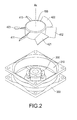
- FIG. 2 is an exploded view of a heat dissipating fan in accordance with the first preferred embodiment of the present invention
- FIG. 3 is a schematic view of vanes installed in a fan wheel in accordance with the first preferred embodiment of the present invention
- FIG. 4 is a side view of a first vane of a fan wheel in accordance with the first preferred embodiment of the present invention
- FIG. 5 is a side view of a second vane of a fan wheel in accordance with the first preferred embodiment of the present invention.
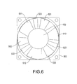
- FIG. 6 is a schematic view of vanes installed in a fan wheel in accordance with a second preferred embodiment of the present invention.
- FIG. 7 is a side view of a third vane of a fan wheel in accordance with the second preferred embodiment of the present invention.
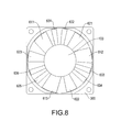
- FIG. 8 is a schematic view of vanes installed in a fan wheel in accordance with a third preferred embodiment of the present invention.
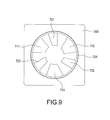
- FIG. 9 is a schematic view of vanes installed in a fan wheel in accordance with a fourth preferred embodiment of the present invention.
- the heat dissipating fan comprises a fan wheel, a drive motor 200, and a frame 300.
- the fan wheel comprises a fan hub 100, a plurality of first vanes 411, 412, 413 (or first blades) and a plurality of second vanes 421, 422, 423 (or second blades).
- the fan hub 100 is made of plastic and in a circular cylindrical shape.
- the frame 300 is made of plastic and in a square shape having a penetrating circular containing space 310.
- the drive motor 200 is mounted onto the frame 300 and disposed at the center of the circular containing space 310, and the fan hub 100 is sheathed on the drive motor 200, and the drive motor 200 is used for driving the fan hub 100 to rotate along an axial line AX.
- the fan wheel of this preferred embodiment comprises three first vanes 411, 412, 413 integrally formed at the fan hub 100, and each first vane 411 412, 413 is extended outwardly from the fan hub 100 in a radial direction of the axial line AX.
- the three first vanes 411, 412, 413 are installed uniformly along the circumferential direction of the axial line AX, and a same first included angle A1 is defined between each first vane 411 412, 413 and the axial line AX, wherein the first included angle A1 is preferably an acute angle.
- the heat dissipating fan of the present invention preferably comprises three second vanes 421, 422, 423 integrally formed at the fan hub 100, and each second vane 421 422, 423 is extended in a radial direction of the axial line AX and outwardly from the fan hub 100.
- the three second vanes 421, 422, 423 are installed uniformly in a circumferential direction of the axial line AX, and a same second included angle A2 is defined between each second vane 421 422, 423 and the axial line AX, wherein the second included angle A2 is preferably an acute angle.
- first vanes 411, 412, 413 and the second vanes 421, 422, 423 have the same appearance, and the three first vanes 411, 412, 413 are installed with the same first included angle A1, and the three second vanes 421, 422, 423 are installed with the same second included angle A2.
- the fan hub 100 can be rotated to drive the first vanes 411, 412, 413 and the second vanes 421, 422, 423 to rotate accordingly.
- a same first included angle A is defined between a chord line C1 of each first vane 411 412, 413 and the axial line AX.
- a same second included angle A2 is defined between a chord line C2 of each second vane 421 422, 423 and the axial line AX.
- the first included angle A1 of the first vane is smaller than the second included angle A2 of the second vane.
- the fan hub 100 drives the first vanes 411, 412, 413 and the second vanes 421, 422, 423 to rotate
- the three first vanes 411, 412, 413 provide a greater airflow in an environment with a smaller flow impedance
- the three second vanes 421, 422, 423 provides a higher wind pressure in an environment with a higher flow impedance.
- the heat dissipating fan comprises a fan wheel, a drive motor 200 and a frame 300.
- the fan wheel comprises a fan hub 100, a plurality of first vanes 511,512,513,a plurality of second vanes 521, 522, 523 and a plurality of third vanes (or blades) 531, 532, 533.
- the fan hub 100, the drive motor 200 and the frame 300 have the same structure and relation as those of the first preferred embodiment, and thus will not be repeated.
- the heat dissipating fan of the present invention preferably comprises three first vanes 511, 512, 513 uniformly installed in a circumferential direction of the axial line AX, three second vanes 521, 522, 523 uniformly installed in a circumferential direction of the axial line AX, and three third vanes 531, 532, 533 uniformly installed in a circumferential direction of the axial line, wherein the first vanes 511, 512, 513, the second vanes 521, 522, 523 and the third vanes 531, 532, 533 preferably have the same appearance and are integrally formed at the fan hub 100 and extended outwardly from the fan hub 100 and in a radial direction of the axial line AX.
- a same first included angle A1 is defined between a chord line C1 (which is a line defined on a cross-section and connecting front and rear edges of a vane) of each first vane 511 512, 513 and the axial line AX as shown in FIG. 4
- a same second included angle A2 is defined between a chord line C2 of each second vane 521 522, 523 and the axial line AX as shown in FIG. 5
- a same third included angle A3 is defined between a chord line C3 of each third vane 531 532, 533 and the axial line AX.
- the first included angle A1 , the second included angle A2 and the second included angle A3 are unequal.
- the first included angle A1 is smaller than the third included angle A3 and the third included angle is smaller than the second included angle (A2 A1 ⁇ A3 ⁇ A2.)
- the heat dissipating fan comprises a fan wheel, a drive motor 200, and a frame 300.
- the fan wheel comprises a fan hub 100, three first vanes 611, 612, 613, six second vanes 621, 622, 623, 624, 625, 626 and three third vanes 631, 632, 633.
- the fan hub 100, the drive motor 200 and the frame 300 have the same structure and relation as those of the first preferred embodiment, and thus will not be repeated.
- a same first included angle A1 is defined between a chord line C1 of each first vane 611 612, 613 and the axial line AX (as shown in FIG. 4 ); and a same second included angle A2 is defined between a chord line C2 of each second vane 621 622, 623, 624, 625, 626 and the axial line AX (as shown in FIG. 5 ); and a same is defined between a chord line C3 of each third vane 631 632, 633 and the axial line AX (as shown in FIG. 7 ).
- the first vanes 611, 612, 613, the second vanes 631, 632, 633, 634, 635, 636 and the third vanes 621, 622, 623 have the same appearance, and are preferably integrally formed at the fan hub 100 and extended outwardly from the fan hub 100 and in a radial direction of the axial line AX, and the first included angle A 1, the second included angle A2 and the third included angle A3 are unequal.
- the first included angle A1 is smaller than the third included angle A3 which is smaller than the second included angle A2 (A1 ⁇ A3 ⁇ A2).
- the heat dissipating fan comprises a fan wheel, a drive motor 200 and a frame 300.
- the fan wheel comprises three first vanes 711, 712, 713, three second vanes 721, 722, 723 and a connecting element 701.
- a same first included angle A1 is defined between a chord line C1 of each first vane 711 712, 713 and the axial line AX as shown in FIG. 4 ; and a same second included angle A2 is defined between a chord line C2 of each second vane 721 722, 723 and the axial line AX as shown in FIG. 5 .
- first vanes 711, 712, 713 and the second vanes 721, 722, 723 have the same appearance, and are extended outwardly from the axial line AX and in a radial direction of the axial line AX, and external ends of the first vanes 711, 712, 713 and the second vanes 721, 722, 723 are connected by a connecting element 701, and the first included angle A1 and the second included angle A2 are unequal.
- first included angle A1 is smaller than the second included angle A2.
- a fan wheel comprising an axial line AX, a radial line perpendicular to the axial line, at least one first vane; e.g. 411, 412, 413 (or 511, 512, 513; or 611, 612, 613); and at least one second vane, e.g. 421, 422, 423 (or 521, 522, 523; or 621, 622, 623, 624, 625, 626) and the first vane(s) and the second vane(s) are extended from the axial line AX, and included angles between chord lines C1, C2 of the first and second vanes and the axial line AX of the fan wheel are unequal angles.
- a heat dissipating fan comprising a fan hub 100, a plurality of first vanes 411, 412, 413 (or 511, 512, 513; or 611, 612, 613) and a plurality of second vanes 421, 422, 423 (or 521, 522, 523; or 621, 622, 623, 624, 625, 626) and the first vanes and the second vanes are extended outwardly from the fan hub 100, and excluded angles between their chord lines C1 , C2 and the axial line AX of the fan hub 100 are unequal angles.
- each vane of the fan wheel provides a different airflow and a different wind pressure, so that the best working efficiency of the vanes can be assured, no matter what is the flow impedance of the installing environment, so as to compensate the working efficiency of the remaining vanes. Therefore, the heat dissipating fan of the present invention can fit casings of different flow impedances.
Priority Applications (1)
| Application Number | Priority Date | Filing Date | Title |
|---|---|---|---|
| EP12167662.1A EP2662573A1 (fr) | 2012-05-11 | 2012-05-11 | Ventilateur de dissipation de chaleur et roue de ventilateur |
Applications Claiming Priority (1)
| Application Number | Priority Date | Filing Date | Title |
|---|---|---|---|
| EP12167662.1A EP2662573A1 (fr) | 2012-05-11 | 2012-05-11 | Ventilateur de dissipation de chaleur et roue de ventilateur |
Publications (1)
| Publication Number | Publication Date |
|---|---|
| EP2662573A1 true EP2662573A1 (fr) | 2013-11-13 |
Family
ID=46087521
Family Applications (1)
| Application Number | Title | Priority Date | Filing Date |
|---|---|---|---|
| EP12167662.1A Withdrawn EP2662573A1 (fr) | 2012-05-11 | 2012-05-11 | Ventilateur de dissipation de chaleur et roue de ventilateur |
Country Status (1)
| Country | Link |
|---|---|
| EP (1) | EP2662573A1 (fr) |
Cited By (1)
| Publication number | Priority date | Publication date | Assignee | Title |
|---|---|---|---|---|
| WO2015124487A3 (fr) * | 2014-02-21 | 2015-10-15 | Ebm-Papst St. Georgen Gmbh & Co. Kg | Ventilateur comprenant un rotor doté de pales mobiles |
Citations (9)
| Publication number | Priority date | Publication date | Assignee | Title |
|---|---|---|---|---|
| DE2524555A1 (de) * | 1974-06-04 | 1975-12-04 | Mitsubishi Heavy Ind Ltd | Axialstroemungsgeblaese |
| US4411598A (en) * | 1979-12-12 | 1983-10-25 | Nissan Motor Company, Limited | Fluid propeller fan |
| JPS59105096U (ja) * | 1982-12-29 | 1984-07-14 | 株式会社東芝 | 送風機 |
| US20020182053A1 (en) * | 2000-01-28 | 2002-12-05 | Atsushi Miyazawa | Axial fan, centrifugal fan, and electronic equipment employing one of these fans |
| US20030063975A1 (en) * | 2001-09-28 | 2003-04-03 | Sunonwealth Electric Machine Industry Co., Ltd. | Impeller structure |
| US20030123975A1 (en) * | 2001-12-27 | 2003-07-03 | Sunonwealth Electric Machine Industry Co., Ltd. | Fan having balancing blade sets |
| US20050019165A1 (en) * | 2002-06-28 | 2005-01-27 | Seiko Epson Corporation | Axial-flow fan and projector provided with the same |
| US20070154314A1 (en) * | 2005-12-29 | 2007-07-05 | Minebea Co., Ltd. | Reduction of tonal noise in cooling fans using splitter blades |
| WO2007085124A1 (fr) * | 2006-01-26 | 2007-08-02 | Hangao Zhao | Pale de ventilateur composite à faible bruit et à flux d'air oscillant |
-
2012
- 2012-05-11 EP EP12167662.1A patent/EP2662573A1/fr not_active Withdrawn
Patent Citations (9)
| Publication number | Priority date | Publication date | Assignee | Title |
|---|---|---|---|---|
| DE2524555A1 (de) * | 1974-06-04 | 1975-12-04 | Mitsubishi Heavy Ind Ltd | Axialstroemungsgeblaese |
| US4411598A (en) * | 1979-12-12 | 1983-10-25 | Nissan Motor Company, Limited | Fluid propeller fan |
| JPS59105096U (ja) * | 1982-12-29 | 1984-07-14 | 株式会社東芝 | 送風機 |
| US20020182053A1 (en) * | 2000-01-28 | 2002-12-05 | Atsushi Miyazawa | Axial fan, centrifugal fan, and electronic equipment employing one of these fans |
| US20030063975A1 (en) * | 2001-09-28 | 2003-04-03 | Sunonwealth Electric Machine Industry Co., Ltd. | Impeller structure |
| US20030123975A1 (en) * | 2001-12-27 | 2003-07-03 | Sunonwealth Electric Machine Industry Co., Ltd. | Fan having balancing blade sets |
| US20050019165A1 (en) * | 2002-06-28 | 2005-01-27 | Seiko Epson Corporation | Axial-flow fan and projector provided with the same |
| US20070154314A1 (en) * | 2005-12-29 | 2007-07-05 | Minebea Co., Ltd. | Reduction of tonal noise in cooling fans using splitter blades |
| WO2007085124A1 (fr) * | 2006-01-26 | 2007-08-02 | Hangao Zhao | Pale de ventilateur composite à faible bruit et à flux d'air oscillant |
Cited By (2)
| Publication number | Priority date | Publication date | Assignee | Title |
|---|---|---|---|---|
| WO2015124487A3 (fr) * | 2014-02-21 | 2015-10-15 | Ebm-Papst St. Georgen Gmbh & Co. Kg | Ventilateur comprenant un rotor doté de pales mobiles |
| US10605269B2 (en) | 2014-02-21 | 2020-03-31 | Ebm-Papst St. Georgen Gmbh & Co. Kg | Fan comprising an impeller with blades |
Similar Documents
| Publication | Publication Date | Title |
|---|---|---|
| EP3133292B1 (fr) | Ventilateur axial et ventilateur pour application en ligne | |
| CN101994713B (zh) | 风扇及具有该风扇的电子装置 | |
| US9062681B2 (en) | Fan device and vane thereof | |
| US20130292096A1 (en) | Heat dissipating fan and fan wheel | |
| US9989072B2 (en) | Fan | |
| US20030026691A1 (en) | Composite heat-dissipating system and its used fan guard with additional supercharging function | |
| EP2565467A2 (fr) | Modules de ventilateur et équipement de serveur | |
| JP2000257597A (ja) | ファンの増圧気流案内装置 | |
| JP4374897B2 (ja) | 軸流ファン | |
| CN103362857A (zh) | 叶轮及风扇 | |
| EP3020976B1 (fr) | Ventilateur d'ordinateur avec paroi de carter face aux extrémités d'aubes structurée pour réduction de bruit | |
| US20120134798A1 (en) | Fan module with multiple cooling fans | |
| JP5890802B2 (ja) | 送風機アセンブリ | |
| JP2013209956A (ja) | 軸流ファン | |
| US11136987B2 (en) | Series-connected fan | |
| US8087887B2 (en) | Fan and fan frame thereof | |
| US7959413B2 (en) | Fan and impeller thereof | |
| US8154866B2 (en) | Single rotor ducted fan | |
| WO2011106020A1 (fr) | Ventilateur à enveloppe hélico-centrifuge | |
| CN105351219B (zh) | 一种风扇装置及电子设备 | |
| EP2662573A1 (fr) | Ventilateur de dissipation de chaleur et roue de ventilateur | |
| JP3176436U (ja) | 散熱ファン及びそのファンホイール | |
| TWM434242U (en) | Heat dissipation fan and fan wheel thereof | |
| WO2021033383A1 (fr) | Ventilateur axial | |
| CN203730412U (zh) | 风扇防震结构及具有风扇防震结构的风扇 |
Legal Events
| Date | Code | Title | Description |
|---|---|---|---|
| PUAI | Public reference made under article 153(3) epc to a published international application that has entered the european phase |
Free format text: ORIGINAL CODE: 0009012 |
|
| AK | Designated contracting states |
Kind code of ref document: A1 Designated state(s): AL AT BE BG CH CY CZ DE DK EE ES FI FR GB GR HR HU IE IS IT LI LT LU LV MC MK MT NL NO PL PT RO RS SE SI SK SM TR |
|
| AX | Request for extension of the european patent |
Extension state: BA ME |
|
| STAA | Information on the status of an ep patent application or granted ep patent |
Free format text: STATUS: THE APPLICATION IS DEEMED TO BE WITHDRAWN |
|
| 18D | Application deemed to be withdrawn |
Effective date: 20140514 |