EP2662556A1 - Mischventil einer Brennkraftmaschine - Google Patents
Mischventil einer Brennkraftmaschine Download PDFInfo
- Publication number
- EP2662556A1 EP2662556A1 EP20120464007 EP12464007A EP2662556A1 EP 2662556 A1 EP2662556 A1 EP 2662556A1 EP 20120464007 EP20120464007 EP 20120464007 EP 12464007 A EP12464007 A EP 12464007A EP 2662556 A1 EP2662556 A1 EP 2662556A1
- Authority
- EP
- European Patent Office
- Prior art keywords
- flap
- mixing valve
- shaft
- flaps
- valve according
- Prior art date
- Legal status (The legal status is an assumption and is not a legal conclusion. Google has not performed a legal analysis and makes no representation as to the accuracy of the status listed.)
- Granted
Links
Images


Classifications
-
- F—MECHANICAL ENGINEERING; LIGHTING; HEATING; WEAPONS; BLASTING
- F16—ENGINEERING ELEMENTS AND UNITS; GENERAL MEASURES FOR PRODUCING AND MAINTAINING EFFECTIVE FUNCTIONING OF MACHINES OR INSTALLATIONS; THERMAL INSULATION IN GENERAL
- F16K—VALVES; TAPS; COCKS; ACTUATING-FLOATS; DEVICES FOR VENTING OR AERATING
- F16K31/00—Actuating devices; Operating means; Releasing devices
- F16K31/44—Mechanical actuating means
- F16K31/53—Mechanical actuating means with toothed gearing
- F16K31/535—Mechanical actuating means with toothed gearing for rotating valves
-
- F—MECHANICAL ENGINEERING; LIGHTING; HEATING; WEAPONS; BLASTING
- F02—COMBUSTION ENGINES; HOT-GAS OR COMBUSTION-PRODUCT ENGINE PLANTS
- F02M—SUPPLYING COMBUSTION ENGINES IN GENERAL WITH COMBUSTIBLE MIXTURES OR CONSTITUENTS THEREOF
- F02M26/00—Engine-pertinent apparatus for adding exhaust gases to combustion-air, main fuel or fuel-air mixture, e.g. by exhaust gas recirculation [EGR] systems
- F02M26/51—EGR valves combined with other devices, e.g. with intake valves or compressors
-
- F—MECHANICAL ENGINEERING; LIGHTING; HEATING; WEAPONS; BLASTING
- F02—COMBUSTION ENGINES; HOT-GAS OR COMBUSTION-PRODUCT ENGINE PLANTS
- F02M—SUPPLYING COMBUSTION ENGINES IN GENERAL WITH COMBUSTIBLE MIXTURES OR CONSTITUENTS THEREOF
- F02M26/00—Engine-pertinent apparatus for adding exhaust gases to combustion-air, main fuel or fuel-air mixture, e.g. by exhaust gas recirculation [EGR] systems
- F02M26/13—Arrangement or layout of EGR passages, e.g. in relation to specific engine parts or for incorporation of accessories
- F02M26/17—Arrangement or layout of EGR passages, e.g. in relation to specific engine parts or for incorporation of accessories in relation to the intake system
- F02M26/21—Arrangement or layout of EGR passages, e.g. in relation to specific engine parts or for incorporation of accessories in relation to the intake system with EGR valves located at or near the connection to the intake system
-
- F—MECHANICAL ENGINEERING; LIGHTING; HEATING; WEAPONS; BLASTING
- F02—COMBUSTION ENGINES; HOT-GAS OR COMBUSTION-PRODUCT ENGINE PLANTS
- F02M—SUPPLYING COMBUSTION ENGINES IN GENERAL WITH COMBUSTIBLE MIXTURES OR CONSTITUENTS THEREOF
- F02M26/00—Engine-pertinent apparatus for adding exhaust gases to combustion-air, main fuel or fuel-air mixture, e.g. by exhaust gas recirculation [EGR] systems
- F02M26/52—Systems for actuating EGR valves
- F02M26/53—Systems for actuating EGR valves using electric actuators, e.g. solenoids
- F02M26/54—Rotary actuators, e.g. step motors
-
- F—MECHANICAL ENGINEERING; LIGHTING; HEATING; WEAPONS; BLASTING
- F02—COMBUSTION ENGINES; HOT-GAS OR COMBUSTION-PRODUCT ENGINE PLANTS
- F02M—SUPPLYING COMBUSTION ENGINES IN GENERAL WITH COMBUSTIBLE MIXTURES OR CONSTITUENTS THEREOF
- F02M26/00—Engine-pertinent apparatus for adding exhaust gases to combustion-air, main fuel or fuel-air mixture, e.g. by exhaust gas recirculation [EGR] systems
- F02M26/52—Systems for actuating EGR valves
- F02M26/64—Systems for actuating EGR valves the EGR valve being operated together with an intake air throttle
-
- F—MECHANICAL ENGINEERING; LIGHTING; HEATING; WEAPONS; BLASTING
- F02—COMBUSTION ENGINES; HOT-GAS OR COMBUSTION-PRODUCT ENGINE PLANTS
- F02M—SUPPLYING COMBUSTION ENGINES IN GENERAL WITH COMBUSTIBLE MIXTURES OR CONSTITUENTS THEREOF
- F02M26/00—Engine-pertinent apparatus for adding exhaust gases to combustion-air, main fuel or fuel-air mixture, e.g. by exhaust gas recirculation [EGR] systems
- F02M26/65—Constructional details of EGR valves
- F02M26/66—Lift valves, e.g. poppet valves
- F02M26/69—Lift valves, e.g. poppet valves having two or more valve-closing members
-
- F—MECHANICAL ENGINEERING; LIGHTING; HEATING; WEAPONS; BLASTING
- F02—COMBUSTION ENGINES; HOT-GAS OR COMBUSTION-PRODUCT ENGINE PLANTS
- F02M—SUPPLYING COMBUSTION ENGINES IN GENERAL WITH COMBUSTIBLE MIXTURES OR CONSTITUENTS THEREOF
- F02M26/00—Engine-pertinent apparatus for adding exhaust gases to combustion-air, main fuel or fuel-air mixture, e.g. by exhaust gas recirculation [EGR] systems
- F02M26/65—Constructional details of EGR valves
- F02M26/70—Flap valves; Rotary valves; Sliding valves; Resilient valves
-
- F—MECHANICAL ENGINEERING; LIGHTING; HEATING; WEAPONS; BLASTING
- F02—COMBUSTION ENGINES; HOT-GAS OR COMBUSTION-PRODUCT ENGINE PLANTS
- F02M—SUPPLYING COMBUSTION ENGINES IN GENERAL WITH COMBUSTIBLE MIXTURES OR CONSTITUENTS THEREOF
- F02M26/00—Engine-pertinent apparatus for adding exhaust gases to combustion-air, main fuel or fuel-air mixture, e.g. by exhaust gas recirculation [EGR] systems
- F02M26/65—Constructional details of EGR valves
- F02M26/71—Multi-way valves
-
- F—MECHANICAL ENGINEERING; LIGHTING; HEATING; WEAPONS; BLASTING
- F16—ENGINEERING ELEMENTS AND UNITS; GENERAL MEASURES FOR PRODUCING AND MAINTAINING EFFECTIVE FUNCTIONING OF MACHINES OR INSTALLATIONS; THERMAL INSULATION IN GENERAL
- F16K—VALVES; TAPS; COCKS; ACTUATING-FLOATS; DEVICES FOR VENTING OR AERATING
- F16K1/00—Lift valves or globe valves, i.e. cut-off apparatus with closure members having at least a component of their opening and closing motion perpendicular to the closing faces
- F16K1/16—Lift valves or globe valves, i.e. cut-off apparatus with closure members having at least a component of their opening and closing motion perpendicular to the closing faces with pivoted closure-members
- F16K1/18—Lift valves or globe valves, i.e. cut-off apparatus with closure members having at least a component of their opening and closing motion perpendicular to the closing faces with pivoted closure-members with pivoted discs or flaps
- F16K1/22—Lift valves or globe valves, i.e. cut-off apparatus with closure members having at least a component of their opening and closing motion perpendicular to the closing faces with pivoted closure-members with pivoted discs or flaps with axis of rotation crossing the valve member, e.g. butterfly valves
-
- F—MECHANICAL ENGINEERING; LIGHTING; HEATING; WEAPONS; BLASTING
- F16—ENGINEERING ELEMENTS AND UNITS; GENERAL MEASURES FOR PRODUCING AND MAINTAINING EFFECTIVE FUNCTIONING OF MACHINES OR INSTALLATIONS; THERMAL INSULATION IN GENERAL
- F16K—VALVES; TAPS; COCKS; ACTUATING-FLOATS; DEVICES FOR VENTING OR AERATING
- F16K11/00—Multiple-way valves, e.g. mixing valves; Pipe fittings incorporating such valves
- F16K11/10—Multiple-way valves, e.g. mixing valves; Pipe fittings incorporating such valves with two or more closure members not moving as a unit
- F16K11/14—Multiple-way valves, e.g. mixing valves; Pipe fittings incorporating such valves with two or more closure members not moving as a unit operated by one actuating member, e.g. a handle
-
- F—MECHANICAL ENGINEERING; LIGHTING; HEATING; WEAPONS; BLASTING
- F16—ENGINEERING ELEMENTS AND UNITS; GENERAL MEASURES FOR PRODUCING AND MAINTAINING EFFECTIVE FUNCTIONING OF MACHINES OR INSTALLATIONS; THERMAL INSULATION IN GENERAL
- F16K—VALVES; TAPS; COCKS; ACTUATING-FLOATS; DEVICES FOR VENTING OR AERATING
- F16K11/00—Multiple-way valves, e.g. mixing valves; Pipe fittings incorporating such valves
- F16K11/10—Multiple-way valves, e.g. mixing valves; Pipe fittings incorporating such valves with two or more closure members not moving as a unit
- F16K11/20—Multiple-way valves, e.g. mixing valves; Pipe fittings incorporating such valves with two or more closure members not moving as a unit operated by separate actuating members
- F16K11/22—Multiple-way valves, e.g. mixing valves; Pipe fittings incorporating such valves with two or more closure members not moving as a unit operated by separate actuating members with an actuating member for each valve, e.g. interconnected to form multiple-way valves
-
- F—MECHANICAL ENGINEERING; LIGHTING; HEATING; WEAPONS; BLASTING
- F16—ENGINEERING ELEMENTS AND UNITS; GENERAL MEASURES FOR PRODUCING AND MAINTAINING EFFECTIVE FUNCTIONING OF MACHINES OR INSTALLATIONS; THERMAL INSULATION IN GENERAL
- F16K—VALVES; TAPS; COCKS; ACTUATING-FLOATS; DEVICES FOR VENTING OR AERATING
- F16K19/00—Arrangements of valves and flow lines specially adapted for mixing fluids
-
- F—MECHANICAL ENGINEERING; LIGHTING; HEATING; WEAPONS; BLASTING
- F16—ENGINEERING ELEMENTS AND UNITS; GENERAL MEASURES FOR PRODUCING AND MAINTAINING EFFECTIVE FUNCTIONING OF MACHINES OR INSTALLATIONS; THERMAL INSULATION IN GENERAL
- F16K—VALVES; TAPS; COCKS; ACTUATING-FLOATS; DEVICES FOR VENTING OR AERATING
- F16K31/00—Actuating devices; Operating means; Releasing devices
- F16K31/02—Actuating devices; Operating means; Releasing devices electric; magnetic
- F16K31/04—Actuating devices; Operating means; Releasing devices electric; magnetic using a motor
- F16K31/041—Actuating devices; Operating means; Releasing devices electric; magnetic using a motor for rotating valves
-
- F—MECHANICAL ENGINEERING; LIGHTING; HEATING; WEAPONS; BLASTING
- F16—ENGINEERING ELEMENTS AND UNITS; GENERAL MEASURES FOR PRODUCING AND MAINTAINING EFFECTIVE FUNCTIONING OF MACHINES OR INSTALLATIONS; THERMAL INSULATION IN GENERAL
- F16K—VALVES; TAPS; COCKS; ACTUATING-FLOATS; DEVICES FOR VENTING OR AERATING
- F16K31/00—Actuating devices; Operating means; Releasing devices
- F16K31/02—Actuating devices; Operating means; Releasing devices electric; magnetic
- F16K31/04—Actuating devices; Operating means; Releasing devices electric; magnetic using a motor
- F16K31/041—Actuating devices; Operating means; Releasing devices electric; magnetic using a motor for rotating valves
- F16K31/043—Actuating devices; Operating means; Releasing devices electric; magnetic using a motor for rotating valves characterised by mechanical means between the motor and the valve, e.g. lost motion means reducing backlash, clutches, brakes or return means
-
- F—MECHANICAL ENGINEERING; LIGHTING; HEATING; WEAPONS; BLASTING
- F16—ENGINEERING ELEMENTS AND UNITS; GENERAL MEASURES FOR PRODUCING AND MAINTAINING EFFECTIVE FUNCTIONING OF MACHINES OR INSTALLATIONS; THERMAL INSULATION IN GENERAL
- F16H—GEARING
- F16H35/00—Gearings or mechanisms with other special functional features
- F16H2035/003—Gearings comprising pulleys or toothed members of non-circular shape, e.g. elliptical gears
-
- Y—GENERAL TAGGING OF NEW TECHNOLOGICAL DEVELOPMENTS; GENERAL TAGGING OF CROSS-SECTIONAL TECHNOLOGIES SPANNING OVER SEVERAL SECTIONS OF THE IPC; TECHNICAL SUBJECTS COVERED BY FORMER USPC CROSS-REFERENCE ART COLLECTIONS [XRACs] AND DIGESTS
- Y10—TECHNICAL SUBJECTS COVERED BY FORMER USPC
- Y10T—TECHNICAL SUBJECTS COVERED BY FORMER US CLASSIFICATION
- Y10T137/00—Fluid handling
- Y10T137/8593—Systems
- Y10T137/87571—Multiple inlet with single outlet
- Y10T137/87676—With flow control
- Y10T137/87684—Valve in each inlet
- Y10T137/87692—With common valve operator
Definitions
- the invention relates to a mixing valve of an internal combustion engine of a motor vehicle with a flap arranged in an intake passage and arranged in an exhaust duct flap, rotatably mounted in a housing, the flaps holding waves, the intake and exhaust ducts open into a common collection channel and with a Drive device for driving the flaps.
- Such mixing valves are often used in exhaust gas recirculation systems of internal combustion engines of modern motor vehicles and are known from practice.
- the movements of the flaps of the intake passage and the exhaust passage are controlled such that the flap disposed in the exhaust passage opens linearly from the first position with a drive signal of the drive means.
- arranged in the intake flap first remains in the first position and is closed only above a provided drive signal.
- the movements of the flaps can be coupled. However, this leads to a strong dependence of the movements of the flaps.
- the simultaneous movement of the flaps is in the fixed context of the movements of the flaps coupling gearbox.
- the invention is based on the problem, so to form a mixing valve of the type mentioned so that the opening and closing movements of the flaps can be designed to be particularly free.
- the drive device has a single servo motor and a transmission for controlling the two flaps and that a one of the flaps driving gear pair has non-circular or eccentric gears.
- the drive of the flaps with different angular velocities structurally particularly simple when one of the non-circular or eccentric gears on the shaft of the flap of the intake port and the other of the non-circular or eccentric gears arranged on the shaft of the flap of the exhaust passage is, and if the transmission is designed to drive a single of the non-circular or eccentric gears.
- a backlash, by which the flap of the intake passage in the drive of the transmission is not pivoted, according to another advantageous embodiment of the invention can be easily generated when mounted on the shaft of the flap of the intake passage, a concentric gear of the transmission and a protruding control arm is attached, and when the concentric gear has a movable against the control arm driver.
- the control of the intake passage and the exhaust passage can be made particularly versatile.
- the mixing valve can be particularly cost-effectively manufacture according to another advantageous embodiment of the invention, when the driver, the concentric gear and the one the non-circular or eccentric gears are made in one piece.
- the drive means driving the flaps could, for example, be self-locking and hold the shafts in a basic position.
- a game in the transmission or a backlash can lead to a momentum of the valves.
- the flaps are reliably held according to another advantageous embodiment of the invention in its intended position when the shaft of the flap of the intake duct is biased by a spring element into a basic position and deflected by the drive means against the force of the spring element.
- the structural complexity for holding the shaft of the flap of the intake duct can be kept particularly low according to another advantageous embodiment of the invention, when a holding element is mounted on the shaft of the flap of the intake duct, and when the spring element supports the holding element relative to the housing.
- the assembly of the mixing valve is particularly simple according to another advantageous embodiment of the invention, when the holding element and the control arm are arranged on opposite ends of the shaft of the flap of the intake passage.
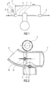
- FIG. 1 schematically shows an internal combustion engine 1 with an intake passage 2 and with an exhaust pipe 3.
- the intake passage 2 has an intake passage 4, is sucked through the air from the environment.
- an exhaust passage 5 via a mixing valve 6 into the intake passage 2.
- the mixing valve 6 performs the intake passage 4 and the exhaust passage 5 to a collecting channel 7 together.
- the collecting channel 7 leads directly to the internal combustion engine 1.
- a drive device 8 with an electric servomotor 9 allows an adjustment of the mixing valve. 6
- FIG. 2 shows a sectional view of the mixing valve 6 FIG. 1 ,
- the intake passage 4 and in the exhaust passage 5 are each a flap 10, 11 mounted on pivotal shafts 12, 13.
- the exhaust passage 5 is arranged at right angles to the intake passage 4 and the collecting passage 7.
- the servomotor 9 is arranged on the exhaust gas channel 5 opposite side of the collecting channel 7.
- the servomotor 9 of the drive device 8 may also be arranged in the corner region between the intake passage 4 and the exhaust passage 5.
- FIG. 3 shows the mixing valve 6 in a plan view of the drive means 8.
- the mixing valve 6 has an open-represented housing 14, which of a in FIG. 4 shown lid 15 is closed.
- the drive device 8 has a gear 26 for driving the shafts 12, 13 and thus the flaps 10, 11.
- the flap 11 in the exhaust duct 5 holding shaft 13 is a gear pair 16 with non-circular or eccentric toothed edges 17, 18 driven.
- the one eccentric or non-circular gear 18 is rotatably mounted on the shaft 13 of the flap 11 of the exhaust passage 5.
- the other eccentric or non-circular gear 17 is rotationally fixed on a concentrically mounted on the shaft 12 of the flap 10 of the intake passage 4 rotatably mounted gear 19.
- This concentric gear 19 has a driver 20 which faces a mounted on the shaft 12 of the flap 10 of the intake passage 4 control arm 21.
- a spring element 22 biases the shaft 13 of the flap 11 of the exhaust duct 5 in a basic position.
- the spring element 22 is supported on the housing 14.
- FIG. 4 shows the mixing valve 6 FIG. 3 in a back view. It can be seen here that the shaft 12 of the flap 10 of the intake duct 4 carries a holding element 23 on its end facing away from the control arm 21. On the holding element 23 engages a second, on the housing 14 supporting spring element 24.
- the drive device 8 from FIG. 3 Covering lid 15 of the housing 14 has a plug connection 25 for energizing the servomotor 9.
- FIG. 2 shows flap 11 of the exhaust passage 5 via the gear 26 and the non-circular or eccentric gear pair 16 driven. Because of the shape of this gear pair 16, the pivoting movement is not linear with the drive, but in an arc, as in FIG. 5 is shown.
- FIG. 5 shows the movement angle of the valve 10 arranged in the intake passage 4 is indicated by I and the movement of the flap 11 arranged in the exhaust passage 5 is indicated by II.
- the flap 10 initially remains in the intake channel 4 in the open position. The drive of the flap 10 in the intake passage 4 thus has a backlash.
Landscapes
- Engineering & Computer Science (AREA)
- General Engineering & Computer Science (AREA)
- Mechanical Engineering (AREA)
- Chemical & Material Sciences (AREA)
- Combustion & Propulsion (AREA)
- Mechanically-Actuated Valves (AREA)
- Multiple-Way Valves (AREA)
- Exhaust-Gas Circulating Devices (AREA)
Abstract
Description
- Die Erfindung betrifft ein Mischventil einer Brennkraftmaschine eines Kraftfahrzeuges mit einer in einem Ansaugkanal angeordneten Klappe und einer in einem Abgaskanal angeordneten Klappe, mit in einem Gehäuse drehbar gelagerten, die Klappen haltenden Wellen, wobei der Ansaugkanal und der Abgaskanal in einen gemeinsamen Sammelkanal münden und mit einer Antriebseinrichtung zum Antrieb der Klappen.
- Solche Mischventile werden bei Abgasrückführungssystemen von Brennkraftmaschinen heutiger Kraftfahrzeuge häufig eingesetzt und sind aus der Praxis bekannt. Die Bewegungen der Klappen des Ansaugkanals und des Abgaskanals sind derart gesteuert, dass die im Abgaskanal angeordnete Klappe ausgehend von der ersten Stellung linear mit einem Ansteuersignal der Antriebseinrichtung öffnet. Die im Ansaugkanal angeordnete Klappe verharrt jedoch zunächst in der ersten Stellung und wird erst oberhalb eines vorgesehenen Ansteuersignals geschlossen.
- Durch einen Einsatz einer einzigen Antriebseinrichtung lassen sich die Bewegungen der Klappen koppeln. Dies führt jedoch zu einer starken Abhängigkeit der Bewegungen der Klappen. Die gleichzeitige Bewegung der Klappen steht im festen Zusammenhang eines die Bewegungen der Klappen koppelnden Getriebes.
- Der Erfindung liegt das Problem zugrunde, ein Mischventil der eingangs genannten Art so weiter zu bilden, dass die Öffnungs- und Schließbewegungen der Klappen besonders frei gestaltet werden können.
- Dieses Problem wird erfindungsgemäß dadurch gelöst, dass die Antriebseinrichtung einen einzigen Stellmotor und ein Getriebe zur Ansteuerung der beiden Klappen aufweist und dass ein eine der Klappen antreibendes Zahnradpaar unrunde oder exzentrische Zahnräder aufweist.
- Durch diese Gestaltung lassen sich unterschiedliche Winkelgeschwindigkeiten der Öffnungs- und Schließbewegungen der Klappen beim konstanten Antrieb der Antriebseinrichtung erzeugen. Ein linearer Zusammenhang der Öffnungs- und Schließbewegungen der gemeinsam angetriebenen Klappen wird dank der Erfindung vermieden. Durch eine entsprechende Festlegung der Unrundheit oder Exzentrizität der Zahnräder lassen sich die Öffnungs- und Schließbewegungen der Klappen bei einem einzigen Stellmotor frei gestalten.
- Der Antrieb der Klappen mit unterschiedlichen Winkelgeschwindigkeiten gestaltet sich gemäß einer anderen vorteilhaften Weiterbildung der Erfindung konstruktiv besonders einfach, wenn eines der unrunden oder exzentrischen Zahnräder auf der Welle der Klappe des Ansaugkanals und das andere der unrunden oder exzentrischen Zahnräder auf der Welle der Klappe des Abgaskanals angeordnet ist, und wenn das Getriebe zum Antrieb eines einzigen der unrunden oder exzentrischen Zahnräder ausgebildet ist.
- Einen Totgang, um den die Klappe des Ansaugkanals beim Antrieb des Getriebes nicht verschwenkt wird, lässt sich gemäß einer anderen vorteilhaften Weiterbildung der Erfindung einfach erzeugen, wenn auf der Welle der Klappe des Ansaugkanals ein konzentrisches Zahnrad des Getriebes gelagert und ein abstehender Steuerarm befestigt ist, und wenn das konzentrische Zahnrad einen gegen den Steuerarm bewegbaren Mitnehmer aufweist. Durch diese Gestaltung lassen sich die Steuerung des Ansaugkanals und des Abgaskanals besonders vielseitig gestalten.
- Das Mischventil lässt sich gemäß einer anderen vorteilhaften Weiterbildung der Erfindung besonders kostengünstig fertigen, wenn der Mitnehmer, das konzentrische Zahnrad und das eine der unrunden oder exzentrischen Zahnräder einstückig gefertigt sind.
- Die die Klappen antreibende Antriebseinrichtung könnte beispielsweise selbsthemmend gestaltet sein und die Wellen in einer Grundstellung halten. Jedoch kann ein Spiel im Getriebe oder ein Totgang zu einer Eigendynamik der Klappen führen. Die Klappen sind gemäß einer anderen vorteilhaften Weiterbildung der Erfindung zuverlässig in ihrer vorgesehenen Lage gehalten, wenn die Welle der Klappe des Ansaugkanals von einem Federelement in eine Grundstellung vorgespannt und von der Antriebseinrichtung gegen die Kraft des Federelementes auslenkbar ist.
- Der bauliche Aufwand zur Halterung der Welle der Klappe des Ansaugkanals lässt sich gemäß einer anderen vorteilhaften Weiterbildung der Erfindung besonders gering halten, wenn ein Halteelement auf der Welle der Klappe des Ansaugkanals befestigt ist, und wenn das Federelement das Halteelement gegenüber dem Gehäuse abstützt.
- Die Montage des Mischventils gestaltet sich gemäß einer anderen vorteilhaften Weiterbildung der Erfindung besonders einfach, wenn das Halteelement und der Steuerarm auf einander gegenüberliegenden Enden der Welle der Klappe des Ansaugkanals angeordnet sind.
- Zur weiteren Verringerung der Eigendynamik der Klappen trägt es gemäß einer anderen vorteilhaften Weiterbildung der Erfindung bei, wenn die Welle der Klappe des Abgaskanals von einem Federelement in eine Grundstellung vorgespannt ist.
- Die Erfindung lässt zahlreiche Ausführungsformen zu. Zur weiteren Verdeutlichung ihres Grundprinzips ist eine davon in der Zeichnung dargestellt und wird nachfolgend beschrieben. Diese zeigt in:
- Fig. 1
- schematisch eine Brennkraftmaschine mit einem erfindungsgemäßen Mischventil,
- Fig. 2
- einen Querschnitt durch das Mischventil aus
Figur 1 , - Fig. 3
- eine Ansicht einer Antriebseinrichtung des Mischventils,
- Fig. 4
- eine rückseitige Ansicht des Mischventils,
- Fig. 5
- schematisch die Schwenkbewegungen von Klappen des Mischventils.
-
Figur 1 zeigt schematisch eine Brennkraftmaschine 1 mit einer Ansaugleitung 2 und mit einer Abgasleitung 3. Die Ansaugleitung 2 hat einen Ansaugkanal 4, über den Luft aus der Umgebung angesaugt wird. Von der Abgasleitung 3 führt ein Abgaskanal 5 über ein Mischventil 6 in die Ansaugleitung 2. Das Mischventil 6 führt den Ansaugkanal 4 und den Abgaskanal 5 zu einem Sammelkanal 7 zusammen. Der Sammelkanal 7 führt unmittelbar zu der Brennkraftmaschine 1. Eine Antriebseinrichtung 8 mit einem elektrischen Stellmotor 9 ermöglicht eine Verstellung des Mischventils 6. -
Figur 2 zeigt eine Schnittdarstellung des Mischventils 6 ausFigur 1 . In dem Ansaugkanal 4 und in dem Abgaskanal 5 sind jeweils eine Klappe 10, 11 auf schwenkbaren Wellen 12, 13 befestigt. Der Abgaskanal 5 ist rechtwinklig zu dem Ansaugkanal 4 und dem Sammelkanal 7 angeordnet. Der Stellmotor 9 ist auf der dem Abgaskanal 5 gegenüberliegenden Seite des Sammelkanals 7 angeordnet. In einer nicht dargestellten alternativen Ausführungsform kann der Stellmotor 9 der Antriebseinrichtung 8 auch im Eckbereich zwischen Ansaugkanal 4 und Abgaskanal 5 angeordnet sein. -
Figur 3 zeigt das Mischventil 6 in einer Draufsicht auf die Antriebseinrichtung 8. Über den Stellmotor 9 und die Antriebseinrichtung 8 werden die Wellen 12, 13 und damit auch die Klappen 10, 11 ausFigur 2 angetrieben. Das Mischventil 6 hat ein geöffnet dargestelltes Gehäuse 14, welches von einem inFigur 4 dargestellten Deckel 15 verschließbar ist. Die Antriebseinrichtung 8 hat ein Getriebe 26 zum Antrieb der Wellen 12, 13 und damit der Klappen 10, 11. Die die Klappe 11 im Abgaskanal 5 haltende Welle 13 ist über ein Zahnradpaar 16 mit unrunden oder exzentrischen Zahnrändern 17, 18 antreibbar. Das eine exzentrische oder unrunde Zahnrad 18 ist auf der Welle 13 der Klappe 11 des Abgaskanals 5 drehfest angeordnet. Das andere exzentrisch oder unrunde Zahnrad 17 ist drehfest auf einem konzentrisch auf der Welle 12 der Klappe 10 des Ansaugkanals 4 drehbar gelagerten Zahnrad 19 angeordnet. Dieses konzentrische Zahnrad 19 weist einen Mitnehmer 20 auf, welcher einem auf der Welle 12 der Klappe 10 des Ansaugkanals 4 befestigten Steuerarm 21 gegenübersteht. Weiterhin spannt ein Federelement 22 die Welle 13 der Klappe 11 des Abgaskanals 5 in eine Grundstellung vor. Hierzu stützt sich das Federelement 22 an dem Gehäuse 14 ab. -
Figur 4 zeigt das Mischventil 6 ausFigur 3 in einer rückseitigen Ansicht. Hierbei ist zu erkennen, dass die Welle 12 der Klappe 10 des Ansaugkanals 4 auf ihrem dem Steuerarm 21 abgewandten Ende ein Halteelement 23 trägt. An dem Halteelement 23 greift ein zweites, sich an dem Gehäuse 14 abstützendes Federelement 24 an. Der die Antriebseinrichtung 8 ausFigur 3 abdeckende Deckel 15 des Gehäuses 14 hat einen Steckanschluss 25 zur Bestromung des Stellmotors 9. - Bei einer Bestromung des Stellmotors 9 wird zunächst die in
Figur 2 dargestellte Klappe 11 des Abgaskanals 5 über das Getriebe 26 und das unrunde oder exzentrische Zahnradpaar 16 angetrieben. Wegen der Form dieses Zahnradpaares 16 verläuft die Schwenkbewegung nicht linear mit dem Antrieb, sondern in einem Bogen, wie es inFigur 5 dargestellt ist.Figur 5 zeigt den Öffnungswinkel α der Klappen 10, 11 über einen Bewegungsbereich der Antriebseinrichtung 8. Die Bewegung der im Ansaugkanal 4 angeordneten Klappe 10 ist mit I und die Bewegung der im Abgaskanal 5 angeordneten Klappe 11 ist mit II gekennzeichnet. Bei der Bewegung des konzentrischen Zahnrades 19 verbleibt die Klappe 10 im Ansaugkanal 4 zunächst in der geöffneten Stellung. Der Antrieb der Klappe 10 im Ansaugkanal 4 hat damit einen Totgang. Wenn das konzentrische Zahnrad 19 des Getriebes 26 soweit verdreht ist, dass der Mitnehmer 20 gegen den auf der Welle 12 der Klappe 10 des Ansaugkanals 4 angeordneten Steuerarm 21 gelangt, wird die Klappe 10 im Ansaugkanal 4 verschwenkt. Diese Schwenkbewegung verläuft linear mit dem Antrieb durch den Stellmotor 9, wie es inFigur 5 dargestellt ist. Der Ansaugkanal 4 wird damit geschlossen.
Claims (8)
- Mischventil (6) einer Brennkraftmaschine (1) eines Kraftfahrzeuges mit einer in einem Ansaugkanal (4) angeordneten Klappe (10) und einer in einem Abgaskanal (5) angeordneten Klappe (11), mit in einem Gehäuse (14) drehbar gelagerten, die Klappen (10, 11) haltenden Wellen (12, 13), wobei der Ansaugkanal (4) und der Abgaskanal (5) in einen gemeinsamen Sammelkanal (7) münden, und mit einer Antriebseinrichtung (8) zum Antrieb der Klappen (10, 11), dadurch gekennzeichnet , dass die Antriebseinrichtung (8) einen einzigen Stellmotor (9) und ein Getriebe (26) zur Ansteuerung der beiden Klappen (10, 11) aufweist, und dass ein eine der Klappen (10, 11) antreibendes Zahnradpaar (16) unrunde oder exzentrische Zahnräder (17, 18) aufweist.
- Mischventil nach Anspruch 1, dadurch gekennzeichnet , dass eines der unrunden oder exzentrischen Zahnräder (17) auf der Welle (12) der Klappe (10) des Ansaugkanals (4) und das andere der unrunden oder exzentrischen Zahnräder (18) auf der Welle (13) der Klappe (11) des Abgaskanals (5) angeordnet ist, und dass das Getriebe (26) zum Antrieb eines einzigen der unrunden oder exzentrischen Zahnräder (17) ausgebildet ist.
- Mischventil nach Anspruch 1 oder 2, dadurch gekennzeichnet , dass auf der Welle (12) der Klappe (10) des Ansaugkanals (4) ein konzentrisches Zahnrad (19) des Getriebes (26) gelagert und ein abstehender Steuerarm (21) befestigt ist, und dass das konzentrische Zahnrad (19) einen gegen den Steuerarm (21) bewegbaren Mitnehmer (20) aufweist.
- Mischventil nach Anspruch 3, dadurch gekennzeichnet, dass der Mitnehmer (20), das konzentrische Zahnrad (19) und das eine der unrunden oder exzentrischen Zahnräder (17, 18) einstückig gefertigt sind.
- Mischventil nach einem der Ansprüche 1 bis 4, dadurch gekennzeichnet , dass die Welle (12) der Klappe (10) des Ansaugkanals (4) von einem Federelement (24) in eine Grundstellung vorgespannt und von der Antriebseinrichtung (8) gegen die Kraft des Federelementes (24) auslenkbar ist.
- Mischventil nach Anspruch 5, dadurch gekennzeichnet , dass ein Halteelement (23) auf der Welle (12) der Klappe (10) des Ansaugkanals (4) befestigt ist, und dass das Federelement (24) das Halteelement (23) gegenüber dem Gehäuse (14) abstützt.
- Mischventil nach Anspruch 6, dadurch gekennzeichnet , dass das Halteelement (23) und der Steuerarm (21) auf einander gegenüberliegenden Enden der Welle (12) der Klappe (10) des Ansaugkanals (4) angeordnet sind.
- Mischventil nach einem der Ansprüche 1 bis 7, dadurch gekennzeichnet , dass die Welle (13) der Klappe (11) des Abgaskanals (5) von einem Federelement (22) in eine Grundstellung vorgespannt ist.
Priority Applications (4)
| Application Number | Priority Date | Filing Date | Title |
|---|---|---|---|
| EP20120464007 EP2662556B1 (de) | 2012-05-09 | 2012-05-09 | Mischventil einer Brennkraftmaschine |
| PCT/EP2013/058961 WO2013167423A1 (de) | 2012-05-09 | 2013-04-30 | Mischventil einer brennkraftmaschine |
| CN201380023157.XA CN104271932B (zh) | 2012-05-09 | 2013-04-30 | 内燃机的混合阀 |
| US14/399,872 US9771898B2 (en) | 2012-05-09 | 2013-04-30 | Mixing valve of an internal combustion engine |
Applications Claiming Priority (1)
| Application Number | Priority Date | Filing Date | Title |
|---|---|---|---|
| EP20120464007 EP2662556B1 (de) | 2012-05-09 | 2012-05-09 | Mischventil einer Brennkraftmaschine |
Publications (2)
| Publication Number | Publication Date |
|---|---|
| EP2662556A1 true EP2662556A1 (de) | 2013-11-13 |
| EP2662556B1 EP2662556B1 (de) | 2015-02-18 |
Family
ID=48227294
Family Applications (1)
| Application Number | Title | Priority Date | Filing Date |
|---|---|---|---|
| EP20120464007 Active EP2662556B1 (de) | 2012-05-09 | 2012-05-09 | Mischventil einer Brennkraftmaschine |
Country Status (4)
| Country | Link |
|---|---|
| US (1) | US9771898B2 (de) |
| EP (1) | EP2662556B1 (de) |
| CN (1) | CN104271932B (de) |
| WO (1) | WO2013167423A1 (de) |
Cited By (1)
| Publication number | Priority date | Publication date | Assignee | Title |
|---|---|---|---|---|
| GB2514374A (en) * | 2013-05-21 | 2014-11-26 | Johnson Electric Sa | Electrically operated valve assembly |
Families Citing this family (3)
| Publication number | Priority date | Publication date | Assignee | Title |
|---|---|---|---|---|
| FR2954407B1 (fr) * | 2009-12-22 | 2018-11-23 | Valeo Systemes De Controle Moteur | Procede de commande d'un circuit egr d'un moteur de vehicule automobile, vanne pour la mise en oeuvre du procede et moteur avec la vanne. |
| CN109751435B (zh) * | 2017-11-07 | 2020-08-25 | 比亚迪股份有限公司 | 集成电动四通换向阀 |
| JP7563328B2 (ja) * | 2021-08-04 | 2024-10-08 | 株式会社デンソー | バルブ装置 |
Citations (8)
| Publication number | Priority date | Publication date | Assignee | Title |
|---|---|---|---|---|
| US4838226A (en) * | 1986-12-12 | 1989-06-13 | Nippondenso Co., Ltd. | Apparatus for controlling intake air flow rate in internal combustion engine |
| US5562081A (en) * | 1995-09-12 | 1996-10-08 | Philips Electronics North America Corporation | Electrically-controlled throttle with variable-ratio drive |
| EP1329618A1 (de) * | 2000-09-20 | 2003-07-23 | Mikuni Corporation | Antriebsvorrichtung mit nichtrundem zahnrad |
| US20050241702A1 (en) * | 2004-03-26 | 2005-11-03 | Stt Emtec Ab | Valve device |
| US20060283430A1 (en) * | 2005-06-17 | 2006-12-21 | Caterpillar Inc. | Throttle and recirculation valves having a common planetary drive |
| DE102005028374A1 (de) * | 2005-06-20 | 2006-12-21 | Robert Bosch Gmbh | Steller für ein Stellorgan |
| EP2317111A1 (de) * | 2009-10-28 | 2011-05-04 | Magneti Marelli S.p.A. | Mischvorrichtung für ein Niederruck-AGR-System einer Brennkraftmaschine |
| DE102011053664A1 (de) * | 2010-09-16 | 2012-04-26 | Denso Corporation | Niederdruck-Umführ-AGR-Vorrichtung |
Family Cites Families (3)
| Publication number | Priority date | Publication date | Assignee | Title |
|---|---|---|---|---|
| WO2011024211A1 (ja) * | 2009-08-24 | 2011-03-03 | 三菱電機株式会社 | バルブ開閉機構 |
| FR2954407B1 (fr) * | 2009-12-22 | 2018-11-23 | Valeo Systemes De Controle Moteur | Procede de commande d'un circuit egr d'un moteur de vehicule automobile, vanne pour la mise en oeuvre du procede et moteur avec la vanne. |
| FR2954408B1 (fr) * | 2009-12-22 | 2015-12-25 | Valeo Sys Controle Moteur Sas | Procede de commande d'un circuit egr d'un moteur de vehicule automobile. |
-
2012
- 2012-05-09 EP EP20120464007 patent/EP2662556B1/de active Active
-
2013
- 2013-04-30 CN CN201380023157.XA patent/CN104271932B/zh active Active
- 2013-04-30 US US14/399,872 patent/US9771898B2/en active Active
- 2013-04-30 WO PCT/EP2013/058961 patent/WO2013167423A1/de not_active Ceased
Patent Citations (8)
| Publication number | Priority date | Publication date | Assignee | Title |
|---|---|---|---|---|
| US4838226A (en) * | 1986-12-12 | 1989-06-13 | Nippondenso Co., Ltd. | Apparatus for controlling intake air flow rate in internal combustion engine |
| US5562081A (en) * | 1995-09-12 | 1996-10-08 | Philips Electronics North America Corporation | Electrically-controlled throttle with variable-ratio drive |
| EP1329618A1 (de) * | 2000-09-20 | 2003-07-23 | Mikuni Corporation | Antriebsvorrichtung mit nichtrundem zahnrad |
| US20050241702A1 (en) * | 2004-03-26 | 2005-11-03 | Stt Emtec Ab | Valve device |
| US20060283430A1 (en) * | 2005-06-17 | 2006-12-21 | Caterpillar Inc. | Throttle and recirculation valves having a common planetary drive |
| DE102005028374A1 (de) * | 2005-06-20 | 2006-12-21 | Robert Bosch Gmbh | Steller für ein Stellorgan |
| EP2317111A1 (de) * | 2009-10-28 | 2011-05-04 | Magneti Marelli S.p.A. | Mischvorrichtung für ein Niederruck-AGR-System einer Brennkraftmaschine |
| DE102011053664A1 (de) * | 2010-09-16 | 2012-04-26 | Denso Corporation | Niederdruck-Umführ-AGR-Vorrichtung |
Cited By (1)
| Publication number | Priority date | Publication date | Assignee | Title |
|---|---|---|---|---|
| GB2514374A (en) * | 2013-05-21 | 2014-11-26 | Johnson Electric Sa | Electrically operated valve assembly |
Also Published As
| Publication number | Publication date |
|---|---|
| EP2662556B1 (de) | 2015-02-18 |
| CN104271932B (zh) | 2017-04-12 |
| US9771898B2 (en) | 2017-09-26 |
| CN104271932A (zh) | 2015-01-07 |
| WO2013167423A1 (de) | 2013-11-14 |
| US20150107707A1 (en) | 2015-04-23 |
Similar Documents
| Publication | Publication Date | Title |
|---|---|---|
| DE102009016597B4 (de) | Abgasklappenantrieb für ein Kraftfahrzeug | |
| EP2180167B1 (de) | Abgasklappenantrieb für ein Kraftfahrzeug | |
| EP2662556B1 (de) | Mischventil einer Brennkraftmaschine | |
| DE102013223231A1 (de) | Zahnsegment mit integrierter Hülse | |
| DE102009049842A1 (de) | Motor mit Körper mit zwei Bohrungen einer progressiven elektronischen Drosselklappe | |
| EP1091112B1 (de) | Ventileinheit, Brennluftansaugkanalabschnitt sowie Abgasrückführeinheit für Brennkraftmaschinen | |
| DE102006054041B3 (de) | Regelvorrichtung für eine Verbrennungskraftmaschine | |
| EP2820284B1 (de) | Mischventil einer brennkraftmaschine | |
| EP1063403B1 (de) | Lastverstellvorrichtung | |
| WO2013149896A1 (de) | Mischventil einer brennkraftmaschine eines kraftfahrzeuges | |
| EP2233729B1 (de) | Klappenvorrichtung für eine Verbrennungskraftmaschine | |
| EP2623765B1 (de) | Abgassteuerungseinrichtung für eine Brennkraftmaschine | |
| EP2653709A1 (de) | Mischventil einer Brennkraftmaschine eines Kraftfahrzeuges | |
| DE102016104102A1 (de) | Antrieb für eine Abgasklappe | |
| DE102006033976A1 (de) | Abgasturbolader für eine Brennkraftmaschine | |
| DE60100768T2 (de) | Abgasrückführvorrichtung für eine Brennkraftmaschine | |
| EP2843223B1 (de) | Mischventil einer Brennkraftmaschine | |
| WO2011032826A1 (de) | Stellvorrichtung und kopplungseinrichtung | |
| DE102010020115A1 (de) | Einrichtung zur Ansteuerung eines Abgasventils einer Brennkraftmaschine | |
| EP2492469A1 (de) | Stellvorrichtung zur Verstellung von Stellgliedern in einer Brennkraftmaschine | |
| WO2013160125A1 (de) | Mischventil einer brennkraftmaschine | |
| DE102008015932B4 (de) | Ventilanordnung | |
| EP3636961B1 (de) | Verbindungsstück zur übertragung einer rotationsbewegung in eine linearbewegung und abgassteuerventil eines kraftfahrzeuges mit einem solchen verbindungsstück | |
| DE102016216361A1 (de) | Klappeneinrichtung für ein Kraftfahrzeug, sowie Kraftfahrzeug mit einer solchen Klappeneinrichtung | |
| DE102008030785A1 (de) | Abgasrückführvorrichtung für eine Verbrennungskraftmaschine |
Legal Events
| Date | Code | Title | Description |
|---|---|---|---|
| PUAI | Public reference made under article 153(3) epc to a published international application that has entered the european phase |
Free format text: ORIGINAL CODE: 0009012 |
|
| AK | Designated contracting states |
Kind code of ref document: A1 Designated state(s): AL AT BE BG CH CY CZ DE DK EE ES FI FR GB GR HR HU IE IS IT LI LT LU LV MC MK MT NL NO PL PT RO RS SE SI SK SM TR |
|
| AX | Request for extension of the european patent |
Extension state: BA ME |
|
| 17P | Request for examination filed |
Effective date: 20140513 |
|
| RBV | Designated contracting states (corrected) |
Designated state(s): AL AT BE BG CH CY CZ DE DK EE ES FI FR GB GR HR HU IE IS IT LI LT LU LV MC MK MT NL NO PL PT RO RS SE SI SK SM TR |
|
| GRAP | Despatch of communication of intention to grant a patent |
Free format text: ORIGINAL CODE: EPIDOSNIGR1 |
|
| INTG | Intention to grant announced |
Effective date: 20140925 |
|
| GRAS | Grant fee paid |
Free format text: ORIGINAL CODE: EPIDOSNIGR3 |
|
| GRAA | (expected) grant |
Free format text: ORIGINAL CODE: 0009210 |
|
| AK | Designated contracting states |
Kind code of ref document: B1 Designated state(s): AL AT BE BG CH CY CZ DE DK EE ES FI FR GB GR HR HU IE IS IT LI LT LU LV MC MK MT NL NO PL PT RO RS SE SI SK SM TR |
|
| REG | Reference to a national code |
Ref country code: GB Ref legal event code: FG4D Free format text: NOT ENGLISH |
|
| REG | Reference to a national code |
Ref country code: CH Ref legal event code: EP |
|
| REG | Reference to a national code |
Ref country code: AT Ref legal event code: REF Ref document number: 710775 Country of ref document: AT Kind code of ref document: T Effective date: 20150315 |
|
| REG | Reference to a national code |
Ref country code: IE Ref legal event code: FG4D Free format text: LANGUAGE OF EP DOCUMENT: GERMAN |
|
| REG | Reference to a national code |
Ref country code: DE Ref legal event code: R096 Ref document number: 502012002285 Country of ref document: DE Effective date: 20150402 |
|
| REG | Reference to a national code |
Ref country code: NL Ref legal event code: VDEP Effective date: 20150218 |
|
| REG | Reference to a national code |
Ref country code: LT Ref legal event code: MG4D |
|
| PG25 | Lapsed in a contracting state [announced via postgrant information from national office to epo] |
Ref country code: ES Free format text: LAPSE BECAUSE OF FAILURE TO SUBMIT A TRANSLATION OF THE DESCRIPTION OR TO PAY THE FEE WITHIN THE PRESCRIBED TIME-LIMIT Effective date: 20150218 Ref country code: HR Free format text: LAPSE BECAUSE OF FAILURE TO SUBMIT A TRANSLATION OF THE DESCRIPTION OR TO PAY THE FEE WITHIN THE PRESCRIBED TIME-LIMIT Effective date: 20150218 Ref country code: NO Free format text: LAPSE BECAUSE OF FAILURE TO SUBMIT A TRANSLATION OF THE DESCRIPTION OR TO PAY THE FEE WITHIN THE PRESCRIBED TIME-LIMIT Effective date: 20150518 Ref country code: SE Free format text: LAPSE BECAUSE OF FAILURE TO SUBMIT A TRANSLATION OF THE DESCRIPTION OR TO PAY THE FEE WITHIN THE PRESCRIBED TIME-LIMIT Effective date: 20150218 Ref country code: LT Free format text: LAPSE BECAUSE OF FAILURE TO SUBMIT A TRANSLATION OF THE DESCRIPTION OR TO PAY THE FEE WITHIN THE PRESCRIBED TIME-LIMIT Effective date: 20150218 Ref country code: FI Free format text: LAPSE BECAUSE OF FAILURE TO SUBMIT A TRANSLATION OF THE DESCRIPTION OR TO PAY THE FEE WITHIN THE PRESCRIBED TIME-LIMIT Effective date: 20150218 |
|
| PG25 | Lapsed in a contracting state [announced via postgrant information from national office to epo] |
Ref country code: IS Free format text: LAPSE BECAUSE OF FAILURE TO SUBMIT A TRANSLATION OF THE DESCRIPTION OR TO PAY THE FEE WITHIN THE PRESCRIBED TIME-LIMIT Effective date: 20150618 Ref country code: GR Free format text: LAPSE BECAUSE OF FAILURE TO SUBMIT A TRANSLATION OF THE DESCRIPTION OR TO PAY THE FEE WITHIN THE PRESCRIBED TIME-LIMIT Effective date: 20150519 Ref country code: NL Free format text: LAPSE BECAUSE OF FAILURE TO SUBMIT A TRANSLATION OF THE DESCRIPTION OR TO PAY THE FEE WITHIN THE PRESCRIBED TIME-LIMIT Effective date: 20150218 Ref country code: RS Free format text: LAPSE BECAUSE OF FAILURE TO SUBMIT A TRANSLATION OF THE DESCRIPTION OR TO PAY THE FEE WITHIN THE PRESCRIBED TIME-LIMIT Effective date: 20150218 Ref country code: LV Free format text: LAPSE BECAUSE OF FAILURE TO SUBMIT A TRANSLATION OF THE DESCRIPTION OR TO PAY THE FEE WITHIN THE PRESCRIBED TIME-LIMIT Effective date: 20150218 |
|
| PG25 | Lapsed in a contracting state [announced via postgrant information from national office to epo] |
Ref country code: RO Free format text: LAPSE BECAUSE OF FAILURE TO SUBMIT A TRANSLATION OF THE DESCRIPTION OR TO PAY THE FEE WITHIN THE PRESCRIBED TIME-LIMIT Effective date: 20150218 Ref country code: CZ Free format text: LAPSE BECAUSE OF FAILURE TO SUBMIT A TRANSLATION OF THE DESCRIPTION OR TO PAY THE FEE WITHIN THE PRESCRIBED TIME-LIMIT Effective date: 20150218 Ref country code: DK Free format text: LAPSE BECAUSE OF FAILURE TO SUBMIT A TRANSLATION OF THE DESCRIPTION OR TO PAY THE FEE WITHIN THE PRESCRIBED TIME-LIMIT Effective date: 20150218 Ref country code: SK Free format text: LAPSE BECAUSE OF FAILURE TO SUBMIT A TRANSLATION OF THE DESCRIPTION OR TO PAY THE FEE WITHIN THE PRESCRIBED TIME-LIMIT Effective date: 20150218 Ref country code: EE Free format text: LAPSE BECAUSE OF FAILURE TO SUBMIT A TRANSLATION OF THE DESCRIPTION OR TO PAY THE FEE WITHIN THE PRESCRIBED TIME-LIMIT Effective date: 20150218 |
|
| REG | Reference to a national code |
Ref country code: DE Ref legal event code: R097 Ref document number: 502012002285 Country of ref document: DE |
|
| PG25 | Lapsed in a contracting state [announced via postgrant information from national office to epo] |
Ref country code: PL Free format text: LAPSE BECAUSE OF FAILURE TO SUBMIT A TRANSLATION OF THE DESCRIPTION OR TO PAY THE FEE WITHIN THE PRESCRIBED TIME-LIMIT Effective date: 20150218 |
|
| PLBE | No opposition filed within time limit |
Free format text: ORIGINAL CODE: 0009261 |
|
| STAA | Information on the status of an ep patent application or granted ep patent |
Free format text: STATUS: NO OPPOSITION FILED WITHIN TIME LIMIT |
|
| REG | Reference to a national code |
Ref country code: CH Ref legal event code: PL |
|
| 26N | No opposition filed |
Effective date: 20151119 |
|
| PG25 | Lapsed in a contracting state [announced via postgrant information from national office to epo] |
Ref country code: CH Free format text: LAPSE BECAUSE OF NON-PAYMENT OF DUE FEES Effective date: 20150531 Ref country code: MC Free format text: LAPSE BECAUSE OF FAILURE TO SUBMIT A TRANSLATION OF THE DESCRIPTION OR TO PAY THE FEE WITHIN THE PRESCRIBED TIME-LIMIT Effective date: 20150218 Ref country code: LI Free format text: LAPSE BECAUSE OF NON-PAYMENT OF DUE FEES Effective date: 20150531 Ref country code: LU Free format text: LAPSE BECAUSE OF FAILURE TO SUBMIT A TRANSLATION OF THE DESCRIPTION OR TO PAY THE FEE WITHIN THE PRESCRIBED TIME-LIMIT Effective date: 20150509 |
|
| REG | Reference to a national code |
Ref country code: IE Ref legal event code: MM4A |
|
| PG25 | Lapsed in a contracting state [announced via postgrant information from national office to epo] |
Ref country code: SI Free format text: LAPSE BECAUSE OF FAILURE TO SUBMIT A TRANSLATION OF THE DESCRIPTION OR TO PAY THE FEE WITHIN THE PRESCRIBED TIME-LIMIT Effective date: 20150218 |
|
| PG25 | Lapsed in a contracting state [announced via postgrant information from national office to epo] |
Ref country code: IE Free format text: LAPSE BECAUSE OF NON-PAYMENT OF DUE FEES Effective date: 20150509 |
|
| REG | Reference to a national code |
Ref country code: FR Ref legal event code: PLFP Year of fee payment: 5 |
|
| PG25 | Lapsed in a contracting state [announced via postgrant information from national office to epo] |
Ref country code: MT Free format text: LAPSE BECAUSE OF FAILURE TO SUBMIT A TRANSLATION OF THE DESCRIPTION OR TO PAY THE FEE WITHIN THE PRESCRIBED TIME-LIMIT Effective date: 20150218 |
|
| GBPC | Gb: european patent ceased through non-payment of renewal fee |
Effective date: 20160509 |
|
| REG | Reference to a national code |
Ref country code: FR Ref legal event code: PLFP Year of fee payment: 6 |
|
| PG25 | Lapsed in a contracting state [announced via postgrant information from national office to epo] |
Ref country code: GB Free format text: LAPSE BECAUSE OF NON-PAYMENT OF DUE FEES Effective date: 20160509 Ref country code: HU Free format text: LAPSE BECAUSE OF FAILURE TO SUBMIT A TRANSLATION OF THE DESCRIPTION OR TO PAY THE FEE WITHIN THE PRESCRIBED TIME-LIMIT; INVALID AB INITIO Effective date: 20120509 Ref country code: SM Free format text: LAPSE BECAUSE OF FAILURE TO SUBMIT A TRANSLATION OF THE DESCRIPTION OR TO PAY THE FEE WITHIN THE PRESCRIBED TIME-LIMIT Effective date: 20150218 Ref country code: BG Free format text: LAPSE BECAUSE OF FAILURE TO SUBMIT A TRANSLATION OF THE DESCRIPTION OR TO PAY THE FEE WITHIN THE PRESCRIBED TIME-LIMIT Effective date: 20150218 |
|
| PG25 | Lapsed in a contracting state [announced via postgrant information from national office to epo] |
Ref country code: CY Free format text: LAPSE BECAUSE OF FAILURE TO SUBMIT A TRANSLATION OF THE DESCRIPTION OR TO PAY THE FEE WITHIN THE PRESCRIBED TIME-LIMIT Effective date: 20150218 |
|
| PG25 | Lapsed in a contracting state [announced via postgrant information from national office to epo] |
Ref country code: BE Free format text: LAPSE BECAUSE OF NON-PAYMENT OF DUE FEES Effective date: 20150531 |
|
| PG25 | Lapsed in a contracting state [announced via postgrant information from national office to epo] |
Ref country code: TR Free format text: LAPSE BECAUSE OF FAILURE TO SUBMIT A TRANSLATION OF THE DESCRIPTION OR TO PAY THE FEE WITHIN THE PRESCRIBED TIME-LIMIT Effective date: 20150218 |
|
| REG | Reference to a national code |
Ref country code: FR Ref legal event code: PLFP Year of fee payment: 7 |
|
| PG25 | Lapsed in a contracting state [announced via postgrant information from national office to epo] |
Ref country code: PT Free format text: LAPSE BECAUSE OF FAILURE TO SUBMIT A TRANSLATION OF THE DESCRIPTION OR TO PAY THE FEE WITHIN THE PRESCRIBED TIME-LIMIT Effective date: 20150218 Ref country code: MK Free format text: LAPSE BECAUSE OF FAILURE TO SUBMIT A TRANSLATION OF THE DESCRIPTION OR TO PAY THE FEE WITHIN THE PRESCRIBED TIME-LIMIT Effective date: 20150218 |
|
| REG | Reference to a national code |
Ref country code: AT Ref legal event code: MM01 Ref document number: 710775 Country of ref document: AT Kind code of ref document: T Effective date: 20170509 |
|
| PG25 | Lapsed in a contracting state [announced via postgrant information from national office to epo] |
Ref country code: AT Free format text: LAPSE BECAUSE OF NON-PAYMENT OF DUE FEES Effective date: 20170509 |
|
| PG25 | Lapsed in a contracting state [announced via postgrant information from national office to epo] |
Ref country code: AL Free format text: LAPSE BECAUSE OF FAILURE TO SUBMIT A TRANSLATION OF THE DESCRIPTION OR TO PAY THE FEE WITHIN THE PRESCRIBED TIME-LIMIT Effective date: 20150218 |
|
| REG | Reference to a national code |
Ref country code: DE Ref legal event code: R081 Ref document number: 502012002285 Country of ref document: DE Owner name: VITESCO TECHNOLOGIES GMBH, DE Free format text: FORMER OWNER: CONTINENTAL AUTOMOTIVE GMBH, 30165 HANNOVER, DE |
|
| REG | Reference to a national code |
Ref country code: DE Ref legal event code: R084 Ref document number: 502012002285 Country of ref document: DE |
|
| REG | Reference to a national code |
Ref country code: DE Ref legal event code: R081 Ref document number: 502012002285 Country of ref document: DE Owner name: SCHAEFFLER TECHNOLOGIES AG & CO. KG, DE Free format text: FORMER OWNER: VITESCO TECHNOLOGIES GMBH, 30165 HANNOVER, DE Ref country code: DE Ref legal event code: R081 Ref document number: 502012002285 Country of ref document: DE Owner name: VITESCO TECHNOLOGIES GMBH, DE Free format text: FORMER OWNER: VITESCO TECHNOLOGIES GMBH, 30165 HANNOVER, DE |
|
| P01 | Opt-out of the competence of the unified patent court (upc) registered |
Effective date: 20230530 |
|
| REG | Reference to a national code |
Ref country code: DE Ref legal event code: R081 Ref document number: 502012002285 Country of ref document: DE Owner name: SCHAEFFLER TECHNOLOGIES AG & CO. KG, DE Free format text: FORMER OWNER: VITESCO TECHNOLOGIES GMBH, 93055 REGENSBURG, DE |
|
| PGFP | Annual fee paid to national office [announced via postgrant information from national office to epo] |
Ref country code: DE Payment date: 20250531 Year of fee payment: 14 |
|
| PGFP | Annual fee paid to national office [announced via postgrant information from national office to epo] |
Ref country code: IT Payment date: 20250527 Year of fee payment: 14 |
|
| PGFP | Annual fee paid to national office [announced via postgrant information from national office to epo] |
Ref country code: FR Payment date: 20250528 Year of fee payment: 14 |