EP2662263A1 - A steering device for a vehicle - Google Patents
A steering device for a vehicle Download PDFInfo
- Publication number
- EP2662263A1 EP2662263A1 EP13166972.3A EP13166972A EP2662263A1 EP 2662263 A1 EP2662263 A1 EP 2662263A1 EP 13166972 A EP13166972 A EP 13166972A EP 2662263 A1 EP2662263 A1 EP 2662263A1
- Authority
- EP
- European Patent Office
- Prior art keywords
- steering
- steering wheel
- vehicle
- rim
- central part
- Prior art date
- Legal status (The legal status is an assumption and is not a legal conclusion. Google has not performed a legal analysis and makes no representation as to the accuracy of the status listed.)
- Granted
Links
Images


Classifications
-
- B—PERFORMING OPERATIONS; TRANSPORTING
- B62—LAND VEHICLES FOR TRAVELLING OTHERWISE THAN ON RAILS
- B62D—MOTOR VEHICLES; TRAILERS
- B62D1/00—Steering controls, i.e. means for initiating a change of direction of the vehicle
- B62D1/02—Steering controls, i.e. means for initiating a change of direction of the vehicle vehicle-mounted
- B62D1/04—Hand wheels
- B62D1/10—Hubs; Connecting hubs to steering columns, e.g. adjustable
- B62D1/105—Non-rotatable hubs, e.g. the central part of the steering wheel not rotating
-
- B—PERFORMING OPERATIONS; TRANSPORTING
- B60—VEHICLES IN GENERAL
- B60H—ARRANGEMENTS OF HEATING, COOLING, VENTILATING OR OTHER AIR-TREATING DEVICES SPECIALLY ADAPTED FOR PASSENGER OR GOODS SPACES OF VEHICLES
- B60H1/00—Heating, cooling or ventilating devices
- B60H1/00271—HVAC devices specially adapted for particular vehicle parts or components and being connected to the vehicle HVAC unit
- B60H1/00292—HVAC devices specially adapted for particular vehicle parts or components and being connected to the vehicle HVAC unit for steering wheels
-
- B—PERFORMING OPERATIONS; TRANSPORTING
- B62—LAND VEHICLES FOR TRAVELLING OTHERWISE THAN ON RAILS
- B62D—MOTOR VEHICLES; TRAILERS
- B62D1/00—Steering controls, i.e. means for initiating a change of direction of the vehicle
- B62D1/02—Steering controls, i.e. means for initiating a change of direction of the vehicle vehicle-mounted
- B62D1/04—Hand wheels
- B62D1/06—Rims, e.g. with heating means; Rim covers
- B62D1/065—Steering wheels with heating and ventilating means
-
- B—PERFORMING OPERATIONS; TRANSPORTING
- B62—LAND VEHICLES FOR TRAVELLING OTHERWISE THAN ON RAILS
- B62D—MOTOR VEHICLES; TRAILERS
- B62D1/00—Steering controls, i.e. means for initiating a change of direction of the vehicle
- B62D1/02—Steering controls, i.e. means for initiating a change of direction of the vehicle vehicle-mounted
- B62D1/16—Steering columns
Definitions
- the invention relates to a steering device to be used in a vehicle.
- the steering device according to the invention can be used in a work vehicle such as a tractor, a combine or an operator machine.
- the steering device according to the invention can be used in a vehicle such as a car, a truck, a bus or the like.
- Known tractors comprise one or more vents for directing warm air or cool air towards the driver, so that a proper temperature can be achieved inside the cab of the tractor.
- the vents are connected to an air distribution system through a series of conduits, which convey to the vents air at the desired temperature.
- vents are usually arranged on the dashboard behind the steering wheel.
- vents located behind the steering wheel are that the steering wheel constitutes an obstacle for air directed from the vents towards the driver. Therefore, air coming from the vents cannot reach directly the face of the driver. This can be uncomfortable especially during summer, when it is desirable to have a flow of cool air directly on the face of the driver.
- An object of the invention is to improve existing vehicles, particularly work vehicles such as tractors, combines or the like, but also standard vehicles such as cars.
- Another object is to improve comfort for the driver of a vehicle, particularly as far as temperature inside the vehicle is concerned.
- Another object is to ensure that air supplied by an air distribution system of a vehicle efficiently warms or cools the driver.
- a steering device for a vehicle comprising a steering wheel including a central part arranged for facing a driver and a rim that can be rotated in order to steer the vehicle, characterized in that the steering wheel further comprises air dispensing means for directing a flow of air towards the driver.
- the flow of air coming from the air dispensing means hits directly the chest or the face of the driver, thereby allowing the warm or cool air to reach quickly the driver. This increases comfort for the driver, who has the impression of being in a vehicle at an ideal temperature even a short time after entering the vehicle.
- the air dispensing means are located in the central part of the steering wheel.
- the central part of the steering wheel is uncoupled from the rim, so that the central part remains stationary while the rim is rotated.
- This embodiment is particularly suitable for vehicles in which a hydraulic connection exists between the steering wheel and the vehicle's wheels.
- the steering wheel when the driver releases the steering wheel after turning to the left or to the right, the steering wheel never returns in a predetermined position around its rotation axis.
- the air dispensing means By uncoupling the central part of the steering wheel from the rim, it is possible to ensure that the air dispensing means have the desired orientation whatever be the angular position of the steering wheel.
- the central part of the steering wheel is rigidly connected to the rim by at least one spoke.
- This embodiment is particularly suitable for vehicles in which the steering wheel is mechanically connected to the vehicle's wheels. In this case, when the driver releases the steering wheel rim, the latter returns in a univocally determined position.
- Figure 1 shows a steering device 1 for a vehicle, particularly a working vehicle such as a tractor, a combine or the like.
- the steering device 1 comprises a steering wheel provided with a steering wheel rim 2, particularly having a circular shape.
- the steering wheel rim 2 can have a structure similar to known steering wheel rims, for example comprising a central core made of a metallic material such as steel.
- the central core can be covered with a layer of polymeric material, for example foamed polyurethane.
- the steering wheel rim 2 can be rotated by an operator around a rotation axis R, shown in Figure 3 , in order to turn the vehicle to the left or to the right.
- the rotation axis R is concentric with the steering wheel rim 2 and perpendicular to a plane defined by the steering wheel rim 2.
- a first bevel gear 3 is fixed relative to the steering wheel rim 2.
- the first bevel gear 3 may be fastened, for example by means of screws that are not shown, to a body 4 arranged concentrically to the rotation axis R.
- a plurality of spokes 5 are provided, each spoke 5 extending radially to connect the body 4 with the steering wheel rim 2.
- three spokes 5 are provided which are arranged at angles of 120° one from another. However, it is possible to use a number of spokes different from three.
- the first bevel gear 3 has a plurality of teeth arranged on a frontal face 6 thereof.
- the first bevel gear 3 has a central hole 7, clearly shown in Figure 5 , whose function will be explained later.
- the body 4 has a central opening which, in the assembled steering device 1, is positioned at the central hole 7 of the first bevel gear 3.
- the steering device 1 further comprises a second bevel gear 11 for meshing directly with the first bevel gear 3. This means that no further bevel gears are interposed between the first bevel gear 3 and the second bevel gear 11, so that the teeth of the first bevel gear 3 engage directly with the teeth of the second bevel gear 11.
- the bevel gears 3, 11 can be so dimensioned that the transmission ratio between the first bevel gear 3 and the second bevel gear 11 is 1:1.
- the number of teeth of the first bevel gear 3 is the same as the number of teeth of the second bevel gear 11.
- the pitch diameter of the first bevel gear 3 is equal to the pitch diameter of the second bevel gear 11.
- the second bevel gear 11 has a structure which is similar to the structure of the first bevel gear 3.
- the second bevel gear 11 has a frontal surface 12 on which the teeth are provided, the frontal surface 12 facing the frontal face 6 of the first bevel gear 3.
- the second bevel gear 11 also has a central hole.
- the second bevel gear 11 can be mounted so as to be fixed relative to a steering shaft 13 of the vehicle, shown in Figure 3 .
- the second bevel gear 11 can be keyed on the steering shaft 13, particularly at an end thereof.
- the second bevel gear 11, together with the steering shaft 13, can be rotated around a longitudinal axis Z by the first bevel gear 3.
- the steering shaft 13 extends along the longitudinal axis Z.
- the longitudinal axis Z is inclined, i.e. oblique, relative to the rotation axis R.
- the longitudinal axis Z forms with the rotation axis R a right or an obtuse angle A, i.e. an angle which is greater than, or equal to, 90° and less than 180°.
- the steering shaft 13 is included in a steering column which, as shown in Figure 6 , further comprises a steering sleeve 38 slidingly coupled to the steering shaft 13.
- An end of the steering shaft 13 opposite the first bevel gear 3 is inserted inside the steering sleeve 38 so that the steering shaft 13 can slide along the longitudinal axis Z relative to the steering sleeve 38, without however rotating relative to the steering sleeve 38.
- the steering column is at least partially housed inside a sleeve 14.
- Bearings 15, for example of the ball type, can be interposed between the steering column and the sleeve 14, as shown in Figures 3 and 6 .
- the steering shaft 13, together with the steering sleeve 38, can thus rotate relative to the sleeve 14.
- a supporting element 16 is provided for rotatingly supporting the first bevel gear 3.
- the supporting element 16 can be connected to the sleeve 14.
- the supporting element 16 is hollow and has a first end 70 and a second end 71.
- the first end 70 and the second end 71 are open, so that a passage is defined in the supporting element 16.
- the supporting element 16 can be made of metal, particularly aluminium, and can be obtained by pressure die-casting.
- the supporting element 16 partially encircles the second bevel gear 11.
- a portion 72 of the supporting element 16 occupies a space defined between the first bevel gear 3 and the second bevel gear 11.
- a cylindrical edge is obtained, which is arranged coaxially with the first gear 3 at the central hole 7 thereof.
- the cylindrical edge provided at the first end 70 can project inside the first gear 3.
- This cylindrical edge carries a supporting bearing 18 for rotatingly supporting the first bevel gear 3.
- an inner ring of the supporting bearing 18 is fixed relative to the supporting element 16 and an outer ring of the supporting bearing 18 is fixed relative to the first bevel gear 3.
- the first bevel gear 3 can be rotated while the supporting element 16 remains stationary.
- the second end 71 of the supporting element 16, opposite the first end 70, can be connected to a tubular element 19, shown in Figure 3 .
- the steering device 1 further comprises a containing element 20 for containing electronic devices and other accessories associated to the steering wheel.
- the containing element 20 can be fastened to the supporting element 16, particularly at the first end 70 of the supporting element 16 which carries the supporting bearing 18.
- the containing element 20 can be made of metal, particularly aluminium, or of plastics, particularly glass reinforced plastics.
- the containing element 20 has a central opening which, in use, is aligned with the central hole 7 of the first bevel gear 3 and with the open first end 70 of the supporting element 16.
- the steering device 1 further comprises a central part or panel 10 which, during use, faces the operator in the driving position.
- the central panel 10 is arranged at a location surrounded by the steering wheel rim 2, particularly concentrically with the steering wheel rim 2.
- the central panel 10 can be defined on a covering element 21 associated to the containing element 20 in order to close the containing element 20.
- the covering element 21 may be removably fixed to the containing element 20, for example by fastening elements such as screws.
- the covering element 21 may have a side wall 8 projecting from the central panel 10 and suitable for contacting the containing element 20 so as to keep the central panel 10 at a distance from the containing element 20.
- control devices are located on the central panel 10.
- the control devices might comprise a display 22 arranged in a central region of the central panel 10 for displaying information concerning the current status and working conditions of the vehicle.
- the display 22 may be a touch-screen display, in which case the operator is not only able to read information displayed on the control display 22, but can also input data or commands for the vehicle.
- the control devices located on the central panel 10 may also comprise switches or push-buttons, for example a start-stop button 23 for starting or stopping an engine of the vehicle, or an emergency button 24.
- control devices can also comprise one or more warning lights located in a region 25 of the central panel 10.
- the central panel 10 can comprise dispensing means 26 for sending a flow of air towards the operator.
- the flow of air may be a flow of warm air, which has been heated by a heating device not shown.
- the flow of air may be a flow of fresh air, particularly cooled by a cooling device to be activated in hot seasons.
- the dispensing means 26 can comprise a grid 27 arranged at a location on the central panel 10, particularly in a region of the central panel 10 which, in use, is proximal to the operator.
- a rotatable knob 28 may be associated to the grid 27 for changing orientation of the grid 27 to direct the flow of air in a desired direction. For example, during summer the operator may appreciate receiving a flow of fresh air in his face, whereas during winter the operator may choose to direct the flow of warm air towards his chest. The flow of air may also be directed towards the operator's fingers while the operator is holding the steering wheel rim 2.
- a partition wall 29 may be provided for defining in the containing element 20 a compartment 30 and a chamber 31.
- the chamber 31 may be positioned, in use, below the grid 27 so as to distribute the flow of air coming from the heating device or the cooling device towards the operator.
- the chamber 31 is at least partially open at the top thereof.
- a conduit 32 opens into the chamber 31 to put the chamber 31 in fluid communication with a distribution system which distributes warm or cooled air inside the vehicle.
- the conduit 32 is defined by the central opening of the containing element 20, by the passage defined internally of the supporting element 16 and by the tubular element 19.
- the compartment 30 defined in the containing element 20 houses certain electric components that are necessary in order that the control devices provided in the central panel may work properly.
- the compartment 30 houses wires, circuits and supports associated with the control devices.
- An electrical cable 33 terminates in the compartment 30 so as to connect the control devices located on the central panel 10 with an electrical power source, for example a battery of the vehicle.
- the cable 33 passes through the tubular element 19, the supporting element 16 and the central opening made in the containing element 20.
- the cable 33 arrives in the compartment 30 through a hole obtained in the partition wall 29.
- the supporting element 16 has therefore a plurality of functions, namely:
- An axial adjusting device 34 can be provided for adjusting the position of the steering wheel along the longitudinal axis Z, according to the operator's needs.
- the axial adjusting device 34 can comprise a gas spring 35 for example of the kind having a lock position.
- the gas spring 35 has a first end 36 connected to the sleeve 14.
- a second end 37 of the gas spring 35, opposite the first end 36, is connected to a frame of the vehicle.
- the gas spring 35 can be lengthened or shortened by displacing the first end 36 parallel to the longitudinal axis Z. When this occurs, the sleeve 14, as well as the steering shaft 13 supported by the sleeve 14, are displaced together with the first end 36 along the longitudinal axis Z. The bevel gears 3, 11, the steering wheel and the components associated thereto are consequently moved far away from, or close to, the operator, until the desired position has been reached.
- the length of the tubular element 19 is also modified.
- a compensation element is associated to the tubular element 19 allowing the length of the tubular element 19 to be modified, in order to compensate for variations in the axial position of the steering shaft 13.
- the compensation element may comprise a bellows 39 obtained in a side wall of the tubular element 19.
- a tilt adjusting device 40 can be provided for adjusting tilting of the steering column, so that the steering wheel can be positioned at a selected angle relative to the ground, or more precisely relative to the floor of the vehicle. This angle is chosen so that the operator sits comfortably on the vehicle during driving.
- the tilt adjusting device 40 may comprise a tilt adjusting gas spring 41, for example having a lock position.
- the tilt adjusting gas spring 41 may have an end 42 connected to a support 43 which supports the steering column.
- a further end 44 of the tilt adjusting gas spring 41 may be connected to the frame of the vehicle.
- the tilt adjusting gas spring 41 may be lengthened or shortened and the end 42 can be moved away from, or close to, the further end 44. Tilt of the steering column, and particularly of the steering shaft 13, can thus be modified according to the operator's wishes.
- the operator may act on the tilt adjusting device 40 by acting on a pedal 45 shown in Figure 6 .
- the pedal 45 may be connected to the tilt adjusting gas spring 41. By acting on the pedal 45, the operator can thus change the angle between the steering shaft 13 and the ground.
- the pedal 45 may also allow the operator to modify axial position of the steering shaft 13.
- the pedal 45 is connected to the gas spring 35 of the axial adjusting device 34. By acting on the pedal 45, the operator can thus control both inclination and axial position of the steering shaft 13.
- the axial adjusting device 34 may be controlled by a control element different from the pedal 45, for example by another pedal or a lever.
- the steering device 1 can be included in a hydraulic power steering system in which a hydraulic fluid is used to steer the vehicle's wheels.
- a pump 46 is provided for sending the hydraulic fluid towards the vehicle's wheels.
- the operator operates a plurality of valves to control flow of the hydraulic fluid.
- the steering shaft 13 and the steering sleeve 38 may be configured to operate on the pump 46 through an interposed shaft 47 connected to the steering sleeve 38 by a universal joint 48.
- the operator acts on the steering wheel by rotating the steering wheel rim 2 clockwise or counter-clockwise around the rotation axis R.
- the body 4, which is connected to the steering wheel rim 2 by the spokes 5, is consequently rotated.
- the first bevel gear 3, which is fixed to the body 4, is also rotated around the rotation axis R.
- the first bevel gear 3 is supported during rotation by the supporting bearing 18, provided on the supporting element 16. The latter remains still.
- the first bevel gear 3 engages the second bevel gear 11 thereby rotating the second bevel gear 11 around the longitudinal axis Z.
- the second bevel gear 11 in turn rotates the steering shaft 13 and more in general the steering column, which causes the vehicle's wheels to steer to the desired direction.
- the steering column is supported during rotation by the bearings 15, mounted inside the sleeve 14 which remains still.
- the central panel 10 When the operator rotates the steering wheel rim 2, the central panel 10 remains still. This occurs because the central panel 10 is mounted on the containing element 20, which in turn is supported by the supporting element 16. As already explained, the latter is not rotated by acting on the steering wheel rim 2.
- control devices located on the central panel 10 can easily see the control devices located on the central panel 10, and act on them, in any position of the steering wheel rim 2, since the position of these control devices is not affected by rotation of the steering wheel rim 2.
- the operator can easily input data and instructions to the control display 22, if the latter is a touch-screen display. If the control display 22 were located on the dashboard, interacting with the control display would be much more complicated for the operator.
- the central panel 10 is easily reachable and visible, comfort for the operator is increased, because the operator does not have to move the upper part of his or her body in order to see or act on the control devices. If on the other hand the control devices were located behind the steering wheel on the dashboard, as frequently occurs in known vehicles, the operator would have to tilt his or her body forward in order to see or reach these control devices.
- the operator can also act on a heating system or conditioning system of the vehicle and have warm air or cool air distributed by the dispensing means 26. Since the latter are associated to the central panel 10, rotation of the steering wheel rim 2 does not influence quantity or direction of the dispensed air.
- only the dispensing means 26 could be provided on the central panel 10, whereas the control display 22, the buttons 23, 24 and the warning lights are missing.
- FIGS 7 and 8 show a steering device 101 according to an alternative embodiment.
- the steering device 101 is particularly suitable for vehicles such as cars, trucks, buses or the like, in which there is a mechanical connection between the steering wheel and the vehicle's wheels.
- the position of the steering wheel when the vehicle is travelling in a straightforward direction is univocally determined.
- the steering device 101 comprises a steering wheel rim 102 connected to a central part 110 of the steering wheel by spokes 105.
- the central part 110 is fixed relative to the steering wheel rim 102.
- dispensing means 126 are provided for dispensing a flow of air towards the driver.
- the flow of air can be either warm or cool according to the driver's preferences, i.e. depending on whether the driver has turned on a heating device or a cooling device of the vehicle.
- the dispensing means 126 may comprise a grid 127 arranged at a desired location on the central part 110, for example in a lower region of the central part 110 close to the steering wheel rim 102.
- the dispensing means 126 further comprise a passage 50 obtained through the thickness of the central part 110 for bringing the flow of air towards the grid 127.
- the passage 50 extends from the grid 127 to a back surface 56 of the central part 110.
- a distributor element 51 is further provided for delivering air to the dispensing means 126.
- the distributor element 51 may comprise a conduit 52 which is fixed relative to a frame of the vehicle and is in fluid communication with the air distribution system of the vehicle.
- the distributor element 51 may comprise a flange 53, for example having a circular shape. A hole is provided in a central region of the flange 53.
- the steering device 101 further comprises a steering shaft 113 connected to the steering wheel, so that the steering shaft 113 is rotated by rotating the steering wheel.
- the steering shaft 113 passes through the hole of the flange 53 and can rotate relative to the flange 53.
- An elastic element 54 can be interposed between the flange 53 and an anti-friction disc 55.
- the anti-friction disc 55 is made of a material having a low coefficient of friction and is intended to be contacted by the back surface 56 of the steering wheel. When the steering wheel is rotated, the back surface 56 slides in contact with the anti-friction disc 55. This reduces friction that must be overcome to rotate the steering wheel.
- Both the anti-friction disc 55 and the elastic element 54 have a central hole through which the steering shaft 113 passes.
- a through opening 57 is made in the anti-friction disc 55 and a further through opening 58 is made in the elastic element 54.
- the through opening 57 and the further through opening 58 have a shape which approximately corresponds to the shape of the cross section of the conduit 52.
- the through opening 57 and the further through opening 58 are aligned with the conduit 52.
- the through openings 57, 58 are also aligned with the passage 50, when the steering wheel is in its rest position corresponding to the vehicle advancing along a straight direction.
- the flow rate of the air sent towards the driver's body is maximum when the vehicle is advancing along a straight direction, in which case substantially the whole cross section of the passage 50 faces the through opening 57.
- the steering wheel is rotated, communication between the passage 50 and the conduit 52 is reduced or even temporarily interrupted.
- a full flow of air towards the operator's body is re-obtained. Comfort for the operator can therefore be kept at good levels.
Landscapes
- Engineering & Computer Science (AREA)
- Mechanical Engineering (AREA)
- Chemical & Material Sciences (AREA)
- Combustion & Propulsion (AREA)
- Transportation (AREA)
- Power Engineering (AREA)
- Physics & Mathematics (AREA)
- Thermal Sciences (AREA)
- Steering Controls (AREA)
Abstract
Description
- The invention relates to a steering device to be used in a vehicle. The steering device according to the invention can be used in a work vehicle such as a tractor, a combine or an operator machine. Alternatively, the steering device according to the invention can be used in a vehicle such as a car, a truck, a bus or the like.
- Known tractors comprise one or more vents for directing warm air or cool air towards the driver, so that a proper temperature can be achieved inside the cab of the tractor. The vents are connected to an air distribution system through a series of conduits, which convey to the vents air at the desired temperature.
- The vents are usually arranged on the dashboard behind the steering wheel.
- A drawback of vents located behind the steering wheel is that the steering wheel constitutes an obstacle for air directed from the vents towards the driver. Therefore, air coming from the vents cannot reach directly the face of the driver. This can be uncomfortable especially during summer, when it is desirable to have a flow of cool air directly on the face of the driver.
- Air coming from the vents located behind the steering wheel hits directly the hands of the driver while he or she is driving. The result is that, during summer, the fingers of the driver are cold, whereas his or her face is still hot. The opposite occurs during winter.
- An object of the invention is to improve existing vehicles, particularly work vehicles such as tractors, combines or the like, but also standard vehicles such as cars.
- Another object is to improve comfort for the driver of a vehicle, particularly as far as temperature inside the vehicle is concerned.
- Another object is to ensure that air supplied by an air distribution system of a vehicle efficiently warms or cools the driver.
- According to the invention, there is provided a steering device for a vehicle, comprising a steering wheel including a central part arranged for facing a driver and a rim that can be rotated in order to steer the vehicle, characterized in that the steering wheel further comprises air dispensing means for directing a flow of air towards the driver.
- Owing to the air dispensing means, warm or cool air directed towards the driver can be supplied directly from the steering wheel. Hence, the steering wheel does not anymore constitute an obstacle for the flow of air coming from an air distribution system of the vehicle.
- Furthermore, there is no risk that the hands of the driver are excessively cooled or heated, due to vents provided on the dashboard at a very short distance from the driver's hands.
- Finally, the flow of air coming from the air dispensing means hits directly the chest or the face of the driver, thereby allowing the warm or cool air to reach quickly the driver. This increases comfort for the driver, who has the impression of being in a vehicle at an ideal temperature even a short time after entering the vehicle.
- In an embodiment, the air dispensing means are located in the central part of the steering wheel.
- In an embodiment, the central part of the steering wheel is uncoupled from the rim, so that the central part remains stationary while the rim is rotated.
- This embodiment is particularly suitable for vehicles in which a hydraulic connection exists between the steering wheel and the vehicle's wheels. In this case, when the driver releases the steering wheel after turning to the left or to the right, the steering wheel never returns in a predetermined position around its rotation axis. By uncoupling the central part of the steering wheel from the rim, it is possible to ensure that the air dispensing means have the desired orientation whatever be the angular position of the steering wheel.
- In an embodiment, the central part of the steering wheel is rigidly connected to the rim by at least one spoke.
- This embodiment is particularly suitable for vehicles in which the steering wheel is mechanically connected to the vehicle's wheels. In this case, when the driver releases the steering wheel rim, the latter returns in a univocally determined position.
- Hence, there is no need to uncouple the steering wheel rim from the central part of the steering wheel in order to ensure that the air dispensing means are in a proper position.
- The invention will be better understood and carried out with reference to the attached drawings, which show some exemplificative and non-limiting embodiments thereof, in which:
-
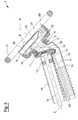
Figure 1 is a schematic perspective view, showing a steering device for a vehicle; -
Figure 2 is a schematic perspective view, showing the steering device ofFigure 1 from the bottom; -
Figure 3 is a cross-section taken along a central longitudinal plane of the steering device ofFigure 1 ; -
Figure 4 is a perspective view of the steering device ofFigure 1 , in which a central plate has been removed; -
Figure 5 is a perspective view of the steering device ofFigure 1 , in which a steering wheel has been removed; -
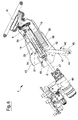
Figure 6 is a cross-section, taken along a longitudinal plane, showing the steering device connected to a hydraulic pump of a vehicle; -
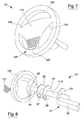
Figure 7 is a schematic perspective view, showing a steering device according to an alternative embodiment; -
Figure 8 is an exploded perspective view of the steering device ofFigure 7 . -
Figure 1 shows asteering device 1 for a vehicle, particularly a working vehicle such as a tractor, a combine or the like. - The
steering device 1 comprises a steering wheel provided with asteering wheel rim 2, particularly having a circular shape. Thesteering wheel rim 2 can have a structure similar to known steering wheel rims, for example comprising a central core made of a metallic material such as steel. The central core can be covered with a layer of polymeric material, for example foamed polyurethane. - The
steering wheel rim 2 can be rotated by an operator around a rotation axis R, shown inFigure 3 , in order to turn the vehicle to the left or to the right. The rotation axis R is concentric with thesteering wheel rim 2 and perpendicular to a plane defined by thesteering wheel rim 2. - A
first bevel gear 3 is fixed relative to thesteering wheel rim 2. In particular, thefirst bevel gear 3 may be fastened, for example by means of screws that are not shown, to abody 4 arranged concentrically to the rotation axis R. A plurality ofspokes 5 are provided, eachspoke 5 extending radially to connect thebody 4 with thesteering wheel rim 2. - In the shown example, three
spokes 5 are provided which are arranged at angles of 120° one from another. However, it is possible to use a number of spokes different from three. - The
first bevel gear 3 has a plurality of teeth arranged on afrontal face 6 thereof. - The
first bevel gear 3 has acentral hole 7, clearly shown inFigure 5 , whose function will be explained later. - Also the
body 4 has a central opening which, in the assembledsteering device 1, is positioned at thecentral hole 7 of thefirst bevel gear 3. - The
steering device 1 further comprises asecond bevel gear 11 for meshing directly with thefirst bevel gear 3. This means that no further bevel gears are interposed between thefirst bevel gear 3 and thesecond bevel gear 11, so that the teeth of thefirst bevel gear 3 engage directly with the teeth of thesecond bevel gear 11. - The
bevel gears first bevel gear 3 and thesecond bevel gear 11 is 1:1. In this case, the number of teeth of thefirst bevel gear 3 is the same as the number of teeth of thesecond bevel gear 11. Also the pitch diameter of thefirst bevel gear 3 is equal to the pitch diameter of thesecond bevel gear 11. - The
second bevel gear 11 has a structure which is similar to the structure of thefirst bevel gear 3. In particular, thesecond bevel gear 11 has afrontal surface 12 on which the teeth are provided, thefrontal surface 12 facing thefrontal face 6 of thefirst bevel gear 3. - The
second bevel gear 11 also has a central hole. - The
second bevel gear 11 can be mounted so as to be fixed relative to asteering shaft 13 of the vehicle, shown inFigure 3 . For example, thesecond bevel gear 11 can be keyed on thesteering shaft 13, particularly at an end thereof. - The
second bevel gear 11, together with thesteering shaft 13, can be rotated around a longitudinal axis Z by thefirst bevel gear 3. Thesteering shaft 13 extends along the longitudinal axis Z. - The longitudinal axis Z is inclined, i.e. oblique, relative to the rotation axis R. In particular, as shown in
Figure 6 , the longitudinal axis Z forms with the rotation axis R a right or an obtuse angle A, i.e. an angle which is greater than, or equal to, 90° and less than 180°. - The steering
shaft 13 is included in a steering column which, as shown inFigure 6 , further comprises asteering sleeve 38 slidingly coupled to the steeringshaft 13. An end of the steeringshaft 13 opposite thefirst bevel gear 3 is inserted inside thesteering sleeve 38 so that the steeringshaft 13 can slide along the longitudinal axis Z relative to thesteering sleeve 38, without however rotating relative to thesteering sleeve 38. - The steering column is at least partially housed inside a
sleeve 14.Bearings 15, for example of the ball type, can be interposed between the steering column and thesleeve 14, as shown inFigures 3 and6 . The steeringshaft 13, together with thesteering sleeve 38, can thus rotate relative to thesleeve 14. - A supporting
element 16 is provided for rotatingly supporting thefirst bevel gear 3. - The supporting
element 16 can be connected to thesleeve 14. - The supporting
element 16 is hollow and has afirst end 70 and asecond end 71. Thefirst end 70 and thesecond end 71 are open, so that a passage is defined in the supportingelement 16. The supportingelement 16 can be made of metal, particularly aluminium, and can be obtained by pressure die-casting. - As shown in
Figure 2 , the supportingelement 16 partially encircles thesecond bevel gear 11. - Furthermore, as shown in
Figure 3 , aportion 72 of the supportingelement 16 occupies a space defined between thefirst bevel gear 3 and thesecond bevel gear 11. - At the
first end 70 of the supporting element 16 a cylindrical edge is obtained, which is arranged coaxially with thefirst gear 3 at thecentral hole 7 thereof. For example, the cylindrical edge provided at thefirst end 70 can project inside thefirst gear 3. This cylindrical edge carries a supportingbearing 18 for rotatingly supporting thefirst bevel gear 3. In particular, an inner ring of the supportingbearing 18 is fixed relative to the supportingelement 16 and an outer ring of the supportingbearing 18 is fixed relative to thefirst bevel gear 3. - Owing to the supporting
bearing 18, thefirst bevel gear 3 can be rotated while the supportingelement 16 remains stationary. - The
second end 71 of the supportingelement 16, opposite thefirst end 70, can be connected to atubular element 19, shown inFigure 3 . - The
steering device 1 further comprises a containingelement 20 for containing electronic devices and other accessories associated to the steering wheel. The containingelement 20 can be fastened to the supportingelement 16, particularly at thefirst end 70 of the supportingelement 16 which carries the supportingbearing 18. - The containing
element 20 can be made of metal, particularly aluminium, or of plastics, particularly glass reinforced plastics. - The containing
element 20 has a central opening which, in use, is aligned with thecentral hole 7 of thefirst bevel gear 3 and with the openfirst end 70 of the supportingelement 16. - The
steering device 1 further comprises a central part orpanel 10 which, during use, faces the operator in the driving position. Thecentral panel 10 is arranged at a location surrounded by thesteering wheel rim 2, particularly concentrically with thesteering wheel rim 2. - The
central panel 10 can be defined on acovering element 21 associated to the containingelement 20 in order to close the containingelement 20. The coveringelement 21 may be removably fixed to the containingelement 20, for example by fastening elements such as screws. - As shown in
Figure 3 , the coveringelement 21 may have aside wall 8 projecting from thecentral panel 10 and suitable for contacting the containingelement 20 so as to keep thecentral panel 10 at a distance from the containingelement 20. - A plurality of control devices are located on the
central panel 10. For example, the control devices might comprise adisplay 22 arranged in a central region of thecentral panel 10 for displaying information concerning the current status and working conditions of the vehicle. Thedisplay 22 may be a touch-screen display, in which case the operator is not only able to read information displayed on thecontrol display 22, but can also input data or commands for the vehicle. - The control devices located on the
central panel 10 may also comprise switches or push-buttons, for example a start-stop button 23 for starting or stopping an engine of the vehicle, or anemergency button 24. - The above mentioned control devices can also comprise one or more warning lights located in a
region 25 of thecentral panel 10. - In addition, or as an alternative, to the control devices which have been described above, the
central panel 10 can comprise dispensing means 26 for sending a flow of air towards the operator. The flow of air may be a flow of warm air, which has been heated by a heating device not shown. As an alternative, the flow of air may be a flow of fresh air, particularly cooled by a cooling device to be activated in hot seasons. - The dispensing means 26 can comprise a
grid 27 arranged at a location on thecentral panel 10, particularly in a region of thecentral panel 10 which, in use, is proximal to the operator. Arotatable knob 28 may be associated to thegrid 27 for changing orientation of thegrid 27 to direct the flow of air in a desired direction. For example, during summer the operator may appreciate receiving a flow of fresh air in his face, whereas during winter the operator may choose to direct the flow of warm air towards his chest. The flow of air may also be directed towards the operator's fingers while the operator is holding thesteering wheel rim 2. - As shown in
Figure 4 , in which thecovering element 21 has been removed for the sake of clarity, inside the containing element 20 apartition wall 29 may be provided for defining in the containing element 20 acompartment 30 and achamber 31. - The
chamber 31 may be positioned, in use, below thegrid 27 so as to distribute the flow of air coming from the heating device or the cooling device towards the operator. Thechamber 31 is at least partially open at the top thereof. - A
conduit 32 opens into thechamber 31 to put thechamber 31 in fluid communication with a distribution system which distributes warm or cooled air inside the vehicle. Theconduit 32 is defined by the central opening of the containingelement 20, by the passage defined internally of the supportingelement 16 and by thetubular element 19. - The
compartment 30 defined in the containingelement 20 houses certain electric components that are necessary in order that the control devices provided in the central panel may work properly. In particular, thecompartment 30 houses wires, circuits and supports associated with the control devices. - Further electric components associated to the above mentioned control devices may be housed in a
recess 73 defined inside the coveringelement 21. - An
electrical cable 33 terminates in thecompartment 30 so as to connect the control devices located on thecentral panel 10 with an electrical power source, for example a battery of the vehicle. - The
cable 33 passes through thetubular element 19, the supportingelement 16 and the central opening made in the containingelement 20. Thecable 33 arrives in thecompartment 30 through a hole obtained in thepartition wall 29. - The supporting
element 16 has therefore a plurality of functions, namely: - rotatingly supporting the
first bevel gear 3 by means of the supportingbearing 18; - positioning the
first bevel gear 3 relative to thesecond bevel gear 11 or to the steeringshaft 13; - supporting the containing
element 20, so that the containingelement 20 remains stationary as thesteering wheel rim 2 rotates; - providing a passage for the flow of air directed towards the dispensing means 26, so as to convey the flow of air along a predetermined path;
- providing a passage for the
electrical cable 33, so as to avoid interference between theelectrical cable 33 and thebevel gears - An
axial adjusting device 34 can be provided for adjusting the position of the steering wheel along the longitudinal axis Z, according to the operator's needs. Theaxial adjusting device 34 can comprise agas spring 35 for example of the kind having a lock position. Thegas spring 35 has afirst end 36 connected to thesleeve 14. Asecond end 37 of thegas spring 35, opposite thefirst end 36, is connected to a frame of the vehicle. - The
gas spring 35 can be lengthened or shortened by displacing thefirst end 36 parallel to the longitudinal axis Z. When this occurs, thesleeve 14, as well as the steeringshaft 13 supported by thesleeve 14, are displaced together with thefirst end 36 along the longitudinal axis Z. The bevel gears 3, 11, the steering wheel and the components associated thereto are consequently moved far away from, or close to, the operator, until the desired position has been reached. - While adjusting the axial position of the steering
shaft 13, the latter can slide relative to thesteering sleeve 38. - As the axial position of the steering
shaft 13 varies, the length of thetubular element 19 is also modified. A compensation element is associated to thetubular element 19 allowing the length of thetubular element 19 to be modified, in order to compensate for variations in the axial position of the steeringshaft 13. As shown inFigure 1 , the compensation element may comprise abellows 39 obtained in a side wall of thetubular element 19. - As shown in
Figure 6 , atilt adjusting device 40 can be provided for adjusting tilting of the steering column, so that the steering wheel can be positioned at a selected angle relative to the ground, or more precisely relative to the floor of the vehicle. This angle is chosen so that the operator sits comfortably on the vehicle during driving. - The
tilt adjusting device 40 may comprise a tilt adjustinggas spring 41, for example having a lock position. The tilt adjustinggas spring 41 may have anend 42 connected to asupport 43 which supports the steering column. Afurther end 44 of the tilt adjustinggas spring 41 may be connected to the frame of the vehicle. - By acting on the
tilt adjusting device 40, the tilt adjustinggas spring 41 may be lengthened or shortened and theend 42 can be moved away from, or close to, thefurther end 44. Tilt of the steering column, and particularly of the steeringshaft 13, can thus be modified according to the operator's wishes. - The operator may act on the
tilt adjusting device 40 by acting on a pedal 45 shown inFigure 6 . The pedal 45 may be connected to the tilt adjustinggas spring 41. By acting on thepedal 45, the operator can thus change the angle between the steeringshaft 13 and the ground. - In an embodiment, the
pedal 45 may also allow the operator to modify axial position of the steeringshaft 13. In this case, thepedal 45 is connected to thegas spring 35 of theaxial adjusting device 34. By acting on thepedal 45, the operator can thus control both inclination and axial position of the steeringshaft 13. - In another embodiment, the
axial adjusting device 34 may be controlled by a control element different from thepedal 45, for example by another pedal or a lever. - As shown in
Figure 6 , thesteering device 1 can be included in a hydraulic power steering system in which a hydraulic fluid is used to steer the vehicle's wheels. In this case, apump 46 is provided for sending the hydraulic fluid towards the vehicle's wheels. By applying a torque on the steering wheel, the operator operates a plurality of valves to control flow of the hydraulic fluid. - The steering
shaft 13 and thesteering sleeve 38 may be configured to operate on thepump 46 through an interposedshaft 47 connected to thesteering sleeve 38 by auniversal joint 48. - During use, the operator acts on the steering wheel by rotating the
steering wheel rim 2 clockwise or counter-clockwise around the rotation axis R. Thebody 4, which is connected to thesteering wheel rim 2 by thespokes 5, is consequently rotated. Thefirst bevel gear 3, which is fixed to thebody 4, is also rotated around the rotation axis R. Thefirst bevel gear 3 is supported during rotation by the supportingbearing 18, provided on the supportingelement 16. The latter remains still. - The
first bevel gear 3 engages thesecond bevel gear 11 thereby rotating thesecond bevel gear 11 around the longitudinal axis Z. Thesecond bevel gear 11 in turn rotates the steeringshaft 13 and more in general the steering column, which causes the vehicle's wheels to steer to the desired direction. - The steering column is supported during rotation by the
bearings 15, mounted inside thesleeve 14 which remains still. - When the operator rotates the
steering wheel rim 2, thecentral panel 10 remains still. This occurs because thecentral panel 10 is mounted on the containingelement 20, which in turn is supported by the supportingelement 16. As already explained, the latter is not rotated by acting on thesteering wheel rim 2. - The operator can easily see the control devices located on the
central panel 10, and act on them, in any position of thesteering wheel rim 2, since the position of these control devices is not affected by rotation of thesteering wheel rim 2. In particular, the operator can easily input data and instructions to thecontrol display 22, if the latter is a touch-screen display. If thecontrol display 22 were located on the dashboard, interacting with the control display would be much more complicated for the operator. - Since the
central panel 10 is easily reachable and visible, comfort for the operator is increased, because the operator does not have to move the upper part of his or her body in order to see or act on the control devices. If on the other hand the control devices were located behind the steering wheel on the dashboard, as frequently occurs in known vehicles, the operator would have to tilt his or her body forward in order to see or reach these control devices. - Furthermore, it is possible to reduce the risk that the operator may temporarily lose control of the vehicle while trying to reach control devices located on the dashboard far away from his or her body.
- The operator can also act on a heating system or conditioning system of the vehicle and have warm air or cool air distributed by the dispensing means 26. Since the latter are associated to the
central panel 10, rotation of thesteering wheel rim 2 does not influence quantity or direction of the dispensed air. - In an embodiment which is not shown, only control devices could be provided on the
central panel 10. In other words, the dispensing means 26 could be missing. - In another embodiment, only the dispensing means 26 could be provided on the
central panel 10, whereas thecontrol display 22, thebuttons -
Figures 7 and 8 show asteering device 101 according to an alternative embodiment. Thesteering device 101 is particularly suitable for vehicles such as cars, trucks, buses or the like, in which there is a mechanical connection between the steering wheel and the vehicle's wheels. In this case, the position of the steering wheel when the vehicle is travelling in a straightforward direction is univocally determined. Hence, there is no need to uncouple the steering wheel rim from the central part of the steering wheel. - The
steering device 101 comprises asteering wheel rim 102 connected to acentral part 110 of the steering wheel byspokes 105. Thecentral part 110 is fixed relative to thesteering wheel rim 102. - On the
central part 110, dispensing means 126 are provided for dispensing a flow of air towards the driver. The flow of air can be either warm or cool according to the driver's preferences, i.e. depending on whether the driver has turned on a heating device or a cooling device of the vehicle. - The dispensing means 126 may comprise a
grid 127 arranged at a desired location on thecentral part 110, for example in a lower region of thecentral part 110 close to thesteering wheel rim 102. - As shown in
Figure 8 , the dispensing means 126 further comprise apassage 50 obtained through the thickness of thecentral part 110 for bringing the flow of air towards thegrid 127. Thepassage 50 extends from thegrid 127 to aback surface 56 of thecentral part 110. - A
distributor element 51 is further provided for delivering air to the dispensing means 126. Thedistributor element 51 may comprise aconduit 52 which is fixed relative to a frame of the vehicle and is in fluid communication with the air distribution system of the vehicle. - The
distributor element 51 may comprise aflange 53, for example having a circular shape. A hole is provided in a central region of theflange 53. - The
steering device 101 further comprises asteering shaft 113 connected to the steering wheel, so that thesteering shaft 113 is rotated by rotating the steering wheel. The steeringshaft 113 passes through the hole of theflange 53 and can rotate relative to theflange 53. - An
elastic element 54 can be interposed between theflange 53 and ananti-friction disc 55. Theanti-friction disc 55 is made of a material having a low coefficient of friction and is intended to be contacted by theback surface 56 of the steering wheel. When the steering wheel is rotated, theback surface 56 slides in contact with theanti-friction disc 55. This reduces friction that must be overcome to rotate the steering wheel. - Both the
anti-friction disc 55 and theelastic element 54 have a central hole through which thesteering shaft 113 passes. A throughopening 57 is made in theanti-friction disc 55 and a further throughopening 58 is made in theelastic element 54. The throughopening 57 and the further through opening 58 have a shape which approximately corresponds to the shape of the cross section of theconduit 52. - In the assembled
steering device 101, the throughopening 57 and the further throughopening 58 are aligned with theconduit 52. The throughopenings passage 50, when the steering wheel is in its rest position corresponding to the vehicle advancing along a straight direction. - The flow rate of the air sent towards the driver's body is maximum when the vehicle is advancing along a straight direction, in which case substantially the whole cross section of the
passage 50 faces the throughopening 57. When the steering wheel is rotated, communication between thepassage 50 and theconduit 52 is reduced or even temporarily interrupted. However, as soon as the steering wheel is returned to its rest position, a full flow of air towards the operator's body is re-obtained. Comfort for the operator can therefore be kept at good levels.
Claims (15)
- A steering device for a vehicle, comprising a steering wheel including a central part (10; 110) arranged for facing a driver and a rim (2; 102) that can be rotated in order to steer the vehicle, characterized in that the steering wheel further comprises air dispensing means (26; 126) for directing an air flow towards the driver.
- A steering device according to claim 1, wherein the air dispensing means (26; 126) are located on the central part (10; 110) of the steering wheel.
- A steering device according to claim 1 or 2, wherein the air dispensing means (26; 126) comprise a grid (27; 127), an adjusting element (28) being preferably provided for adjusting orientation of the grid (28).
- A steering device according to any preceding claim, and further comprising a conduit (32; 52) for conveying towards the steering wheel the air flow coming from an air distribution system of the vehicle.
- A steering device according to any preceding claim, wherein the central part (10) of the steering wheel in uncoupled from the rim (2), so that the central part (10) remains stationary as the rim (2) is rotated.
- A steering device according to claim 5, as appended to claim 4, wherein the conduit (32) passes in a central hole of a gear (3), the gear (3) being fixed relative to the rim (2) for transmitting rotation from the rim (2) to a steering shaft (13) of the vehicle.
- A steering device according to claim 5 or 6, and further comprising a containing body (20) uncoupled from the rim (2) and a covering element (21) closing the containing body (20), said central part (2) being defined on the covering element (21).
- A device according to claim 7, as claim 5 is appended to claim 4, wherein said conduit (32) opens in a chamber (31) defined in the containing body (20).
- A device according to any preceding claim, and further comprising at least one control device (22, 23, 24) located in said central part (10) for controlling the vehicle during operation.
- A device according to claim 9, as appended to claim 8, wherein the containing body (20) comprises a partition wall (29) for dividing the chamber (31) from a compartment (30) which houses at least partially the control device (22, 23, 24).
- A device according to claim 9 or 10, as claim 9 is appended to claim 4, wherein an electric cable (33) passes through said conduit (32), said electric cable (33) being connected to the control device (22, 23, 24).
- A steering device according to any one of claims 1 to 4, wherein the central part (110) of the steering wheel is rigidly connected to the rim (102) by at least one spoke (105).
- A steering device according to claim 12, as appended to claim 4, wherein the air dispensing means (126) further comprise a passage (50) obtained in the central part (110) of the steering wheel, the passage (50) being in fluid communication with the conduit (52) through a cross section having an area which varies as the rim (102) is rotated relative to the conduit (52).
- A steering device according to any preceding claim, and further comprising an axial adjusting device (34) for adjusting distance between the steering wheel and the driver and/or a tilt adjusting device (40) for adjusting tilting of the steering wheel relative to a floor of the vehicle.
- A steering device according to claim 14, as appended to claim 4, wherein the axial adjusting device (34) comprises a length compensation element (39) including for example a bellows, the length compensation element (39) being provided along the conduit (32) for allowing length of the conduit (32) to be varied.
Applications Claiming Priority (1)
| Application Number | Priority Date | Filing Date | Title |
|---|---|---|---|
| IT000125A ITMO20120125A1 (en) | 2012-05-11 | 2012-05-11 | STEERING DEVICE FOR A VEHICLE. |
Publications (2)
| Publication Number | Publication Date |
|---|---|
| EP2662263A1 true EP2662263A1 (en) | 2013-11-13 |
| EP2662263B1 EP2662263B1 (en) | 2016-10-26 |
Family
ID=46548664
Family Applications (1)
| Application Number | Title | Priority Date | Filing Date |
|---|---|---|---|
| EP13166972.3A Active EP2662263B1 (en) | 2012-05-11 | 2013-05-08 | A steering device for a vehicle |
Country Status (3)
| Country | Link |
|---|---|
| US (1) | US9090282B2 (en) |
| EP (1) | EP2662263B1 (en) |
| IT (1) | ITMO20120125A1 (en) |
Cited By (2)
| Publication number | Priority date | Publication date | Assignee | Title |
|---|---|---|---|---|
| CN108025682A (en) * | 2015-08-06 | 2018-05-11 | 凯斯纽荷兰(中国)管理有限公司 | System for device to be installed to the wheel hub to the fixation of steering wheel |
| CN111497924A (en) * | 2020-07-01 | 2020-08-07 | 潍坊学院 | Multifunctional steering wheel |
Families Citing this family (61)
| Publication number | Priority date | Publication date | Assignee | Title |
|---|---|---|---|---|
| ITMO20120125A1 (en) * | 2012-05-11 | 2013-11-12 | Cnh Italia Spa | STEERING DEVICE FOR A VEHICLE. |
| US9637062B2 (en) * | 2014-01-31 | 2017-05-02 | Stephen Tyrer | Apparatus for holding an electronic device on a golf cart |
| WO2015149248A1 (en) * | 2014-03-31 | 2015-10-08 | Gentherm Automotive Systems (China) Ltd. | Heating and cooling device for handles |
| KR20170093569A (en) * | 2016-02-05 | 2017-08-16 | 울산과학기술원 | Method and apparatus for providing combined monitoring system |
| USD811296S1 (en) * | 2016-02-05 | 2018-02-27 | Cnh Industrial America Llc | Portable electronic device mount for a vehicle steering wheel |
| USD852693S1 (en) * | 2016-09-12 | 2019-07-02 | Deere & Company | Cowl assembly for a vehicle |
| USD851564S1 (en) * | 2016-09-16 | 2019-06-18 | Deere & Company | Cowl assembly for a vehicle |
| USD870004S1 (en) * | 2017-05-22 | 2019-12-17 | Aston Martin Lagonda Limited | Steering wheel for automobile or replica thereof |
| USD824302S1 (en) * | 2017-08-25 | 2018-07-31 | Cnh Industrial America Llc | Control interface screen for a vehicle steering wheel |
| USD878980S1 (en) * | 2017-08-29 | 2020-03-24 | Jaguar Land Rover Limited | Steering wheel for a vehicle |
| USD899328S1 (en) | 2017-09-05 | 2020-10-20 | Byton Limited | Steering wheel |
| USD853290S1 (en) * | 2017-09-08 | 2019-07-09 | Trw Automotive Safety Systems Gmbh | Vehicle steering wheel |
| US11407436B2 (en) | 2019-03-04 | 2022-08-09 | Byton North America Corporation | Steering wheel with fixed center |
| USD940614S1 (en) * | 2019-04-16 | 2022-01-11 | Lg Electronics Inc. | Automobile |
| USD918106S1 (en) * | 2019-08-14 | 2021-05-04 | Hyundai Motor Company | Steering wheel with display screen for an automobile |
| US11458801B2 (en) * | 2019-08-28 | 2022-10-04 | Ford Global Technologies, Llc | Steering wheel preconditioning |
| AT522442B1 (en) | 2019-11-08 | 2020-11-15 | Ivan Tochev | Arrangement of a steering device |
| USD1131647S1 (en) | 2020-05-22 | 2026-06-23 | Rubber Road Ltd. | Game console steering wheel |
| USD979653S1 (en) * | 2020-05-22 | 2023-02-28 | Rubber Road Ltd. | Game console steering wheel |
| USD983270S1 (en) * | 2020-05-22 | 2023-04-11 | Rubber Road Ltd. | Game console steering wheel |
| USD1094186S1 (en) | 2021-01-27 | 2025-09-23 | Aston Martin Lagonda Limited | Automobile or replica thereof |
| JP2022146537A (en) * | 2021-03-22 | 2022-10-05 | 本田技研工業株式会社 | Steering device |
| USD1049926S1 (en) | 2021-06-29 | 2024-11-05 | Aston Martin Lagonda Limited | Automobile body and/or replica |
| USD1064920S1 (en) | 2021-10-01 | 2025-03-04 | Aston Martin Lagonda Limited | Automobile body and/or replica |
| USD1053761S1 (en) | 2021-10-19 | 2024-12-10 | Aston Martin Lagonda Limited | Automobile grille |
| USD1029704S1 (en) | 2021-10-19 | 2024-06-04 | Aston Martin Lagonda Limited | Grille for automobile or replica thereof |
| USD1069658S1 (en) | 2021-11-19 | 2025-04-08 | Aston Martin Lagonda Limited | Automobile nose or replica thereof |
| USD1062530S1 (en) | 2021-11-19 | 2025-02-18 | Aston Martin Lagonda Limited | Automobile side strake or replica thereof |
| USD1061339S1 (en) | 2021-11-19 | 2025-02-11 | Aston Martin Lagonda Limited | Automobile body and/or other replica |
| USD1081496S1 (en) | 2021-11-19 | 2025-07-01 | Aston Martin Lagonda Limited | Automobile side strake or replica thereof |
| USD1071811S1 (en) | 2021-11-19 | 2025-04-22 | Aston Martin Lagonda Limited | Automobile bonnet or replica thereof |
| JP1723065S (en) | 2021-11-19 | 2025-08-29 | passenger cars | |
| USD1068580S1 (en) | 2021-11-19 | 2025-04-01 | Aston Martin Lagonda Limited | Automobile nose or replica thereof |
| USD1060130S1 (en) | 2021-11-19 | 2025-02-04 | Aston Martin Lagonda Limited | Automobile body and/or replica |
| USD1038835S1 (en) | 2021-11-22 | 2024-08-13 | Aston Martin Lagonda Limited | Automobile body and/or replica |
| USD1052494S1 (en) | 2022-08-04 | 2024-11-26 | Aston Martin Lagonda Limited | Automobile side aero feature or replica thereof |
| USD1066185S1 (en) | 2022-08-04 | 2025-03-11 | Aston Martin Lagonda Limited | Automobile interior or replica thereof |
| USD1064925S1 (en) | 2022-08-04 | 2025-03-04 | Aston Martin Lagonda Limited | Automobile body and/or replica |
| USD1109032S1 (en) | 2022-08-04 | 2026-01-13 | Aston Martin Lagonda Limited | Grille for automobile or replica thereof |
| USD1061341S1 (en) | 2022-08-04 | 2025-02-11 | Aston Martin Lagonda Limited | Automobile body and/or replica |
| USD1053398S1 (en) | 2022-08-04 | 2024-12-03 | Aston Martin Lagonda Limited | Rear light blade for an automobile or replica thereof |
| USD1054352S1 (en) | 2022-08-04 | 2024-12-17 | Aston Martin Lagonda Limited | Side vent for automobile or replica thereof |
| USD1059233S1 (en) | 2022-11-04 | 2025-01-28 | Aston Martin Lagonda Limited | Bonnet vent for automobile or replica thereof |
| USD1063745S1 (en) | 2022-11-04 | 2025-02-25 | Aston Martin Lagonda Limited | Bonnet for automobile or replica thereof |
| USD1116946S1 (en) | 2023-02-09 | 2026-03-10 | Aston Martin Lagonda Limited | Steering wheel for automobile or replica thereof |
| USD1087848S1 (en) | 2023-02-09 | 2025-08-12 | Aston Martin Lagonda Limited | Dashboard for automobile or replica thereof |
| USD1087852S1 (en) | 2023-02-09 | 2025-08-12 | Aston Martin Lagonda Limited | Air vent for automobile or replica thereof |
| USD1130813S1 (en) | 2023-04-28 | 2026-06-16 | Aston Martin Lagonda Limited | Headlight for automobile or replica thereof |
| USD1110911S1 (en) | 2023-04-28 | 2026-02-03 | Aston Martin Lagonda Limited | Window cover for automobile or replica thereof |
| USD1087849S1 (en) | 2023-04-28 | 2025-08-12 | Aston Martin Lagonda Limited | Binnacle for automobile or replica thereof |
| USD1103046S1 (en) | 2023-04-28 | 2025-11-25 | Aston Martin Lagonda Limited | Diffuser assembly for automobile or replica thereof |
| USD1120810S1 (en) | 2023-04-28 | 2026-03-31 | Aston Martin Lagonda Limited | Automobile or replica thereof |
| USD1123720S1 (en) | 2023-06-19 | 2026-04-28 | Aston Martin Lagonda Limited. | Automobile or replica thereof |
| USD1110928S1 (en) | 2023-06-19 | 2026-02-03 | Aston Martin Lagonda Limited | Console for automobile or replica thereof |
| CN116654076B (en) * | 2023-06-28 | 2025-08-22 | 东风商用车有限公司 | Adjustable steering wheel assembly and vehicle |
| USD1128503S1 (en) | 2023-08-18 | 2026-06-02 | Aston Martin Lagonda Limited | Automobile or replica thereof |
| USD1114672S1 (en) | 2023-10-09 | 2026-02-24 | Aston Martin Lagonda Limited | Panel for automobile or replica thereof |
| JP1780897S (en) | 2023-10-09 | 2024-09-27 | Passenger cars | |
| JP1780505S (en) | 2023-10-23 | 2024-09-24 | Passenger cars | |
| USD1121511S1 (en) | 2023-12-18 | 2026-04-07 | Aston Martin Lagonda Limited | Engine cover for automobile or replica thereof |
| USD1118443S1 (en) | 2024-04-05 | 2026-03-17 | Aston Martin Lagonda Limited | Grille assembly for automobile or replica thereof |
Citations (7)
| Publication number | Priority date | Publication date | Assignee | Title |
|---|---|---|---|---|
| DE2164976A1 (en) * | 1971-12-28 | 1973-07-12 | Helmut Mayer | DEVICE FOR HEATING OR COOLING THE STEERING DRIVES OF VEHICLES |
| DE2322484A1 (en) * | 1973-05-04 | 1974-11-21 | Volkswagenwerk Ag | STEERING WHEEL ARRANGEMENT, IN PARTICULAR FOR MOTOR VEHICLES |
| DE2823528A1 (en) * | 1978-05-30 | 1979-12-06 | Porsche Ag | Facial fresh air duct for driver - has outlet mounted in centre of steering wheel on pivoted support |
| DE19708092A1 (en) * | 1997-02-28 | 1998-09-03 | Bayerische Motoren Werke Ag | Steering wheel with facility for feed of cooling air |
| DE19953467A1 (en) * | 1999-11-05 | 2001-05-17 | Webasto Systemkomponenten Gmbh | Ventilation device for steering wheel of vehicle has fan in steering wheel generating air flow at steering wheel and grip part of steering wheel has air channels |
| FR2922178A1 (en) * | 2007-10-11 | 2009-04-17 | Peugeot Citroen Automobiles Sa | Steering wheel for motor vehicle, has thermo-regulated air flow delivery device opened in space between hub and hub covering module, where space is formed to evenly steer thermo-regulated air on entire internal periphery of wheel rim |
| FR2949413A1 (en) * | 2009-08-26 | 2011-03-04 | Peugeot Citroen Automobiles Sa | Cockpit for cab interior of motor vehicle, has air distribution units i.e. vents, for distributing air inside cab interior without interfering with handset, where handset and vents are supported in whole or in part by fascia |
Family Cites Families (20)
| Publication number | Priority date | Publication date | Assignee | Title |
|---|---|---|---|---|
| US4562957A (en) * | 1981-02-03 | 1986-01-07 | Nippon Soken, Inc. | Air conditioning/heating apparatus for automobiles |
| US4608550A (en) * | 1981-08-25 | 1986-08-26 | Aisin Seiki Kabushikikaisha | Electric signal transmission system on a road vehicle |
| US5152358A (en) * | 1989-08-24 | 1992-10-06 | Mitsubishi Jidosha Kogyo Kabushiki Kaisha | Vehicle steering apparatus |
| JPH09150747A (en) * | 1995-11-28 | 1997-06-10 | Katayama Kogyo Kk | Collapsible steering shaft |
| DE59809761D1 (en) * | 1997-04-16 | 2003-11-06 | Volkswagen Ag | Steering column for occupant protection devices and safety steering |
| JPH11152045A (en) * | 1997-11-21 | 1999-06-08 | Yazaki Corp | Steering module |
| US6533184B1 (en) * | 1999-10-18 | 2003-03-18 | Kiwan Kim | Comfort steering wheel |
| DE10059928C2 (en) * | 2000-11-23 | 2003-07-17 | Takata Petri Ag | Steering device for a motor vehicle |
| JP2005075250A (en) * | 2003-09-03 | 2005-03-24 | Nsk Ltd | Shock absorbing steering column device with telescopic mechanism |
| GB2411942A (en) * | 2004-03-10 | 2005-09-14 | Autoliv Dev | Steering wheel bearing housing with resilient bearing retainers |
| GB2411937A (en) * | 2004-03-11 | 2005-09-14 | Autoliv Dev | Anti-backlash mechanism for the gear of a steering wheel |
| WO2005100097A1 (en) * | 2004-03-31 | 2005-10-27 | Thyssenkrupp Presta Ag | Airbag assembly, gear and operating method for said assembly |
| US20060121843A1 (en) * | 2004-12-07 | 2006-06-08 | Nissan Technical Center North America, Inc. | Steering wheel ventilation system and method |
| US7380828B2 (en) * | 2005-03-09 | 2008-06-03 | Delphi Technologies, Inc. | Stationary wheel hub |
| CA2610886A1 (en) * | 2005-06-06 | 2006-12-14 | Joneso Design And Consulting, Inc. | Vehicle information/control system |
| DE102005053182A1 (en) * | 2005-11-03 | 2007-05-10 | Valeo Schalter Und Sensoren Gmbh | Device for a steering system, in particular of a motor vehicle |
| DE102006005736A1 (en) * | 2006-02-07 | 2007-08-09 | Thyssenkrupp Presta Ag | corrugated pipe |
| KR100980928B1 (en) * | 2007-12-15 | 2010-09-07 | 현대자동차주식회사 | Vehicle steering with non-rotating airbag module |
| US7614682B1 (en) * | 2009-01-13 | 2009-11-10 | Gm Global Technology Operations, Inc. | Steering assembly HVAC system |
| ITMO20120125A1 (en) * | 2012-05-11 | 2013-11-12 | Cnh Italia Spa | STEERING DEVICE FOR A VEHICLE. |
-
2012
- 2012-05-11 IT IT000125A patent/ITMO20120125A1/en unknown
-
2013
- 2013-04-30 US US13/873,781 patent/US9090282B2/en active Active
- 2013-05-08 EP EP13166972.3A patent/EP2662263B1/en active Active
Patent Citations (7)
| Publication number | Priority date | Publication date | Assignee | Title |
|---|---|---|---|---|
| DE2164976A1 (en) * | 1971-12-28 | 1973-07-12 | Helmut Mayer | DEVICE FOR HEATING OR COOLING THE STEERING DRIVES OF VEHICLES |
| DE2322484A1 (en) * | 1973-05-04 | 1974-11-21 | Volkswagenwerk Ag | STEERING WHEEL ARRANGEMENT, IN PARTICULAR FOR MOTOR VEHICLES |
| DE2823528A1 (en) * | 1978-05-30 | 1979-12-06 | Porsche Ag | Facial fresh air duct for driver - has outlet mounted in centre of steering wheel on pivoted support |
| DE19708092A1 (en) * | 1997-02-28 | 1998-09-03 | Bayerische Motoren Werke Ag | Steering wheel with facility for feed of cooling air |
| DE19953467A1 (en) * | 1999-11-05 | 2001-05-17 | Webasto Systemkomponenten Gmbh | Ventilation device for steering wheel of vehicle has fan in steering wheel generating air flow at steering wheel and grip part of steering wheel has air channels |
| FR2922178A1 (en) * | 2007-10-11 | 2009-04-17 | Peugeot Citroen Automobiles Sa | Steering wheel for motor vehicle, has thermo-regulated air flow delivery device opened in space between hub and hub covering module, where space is formed to evenly steer thermo-regulated air on entire internal periphery of wheel rim |
| FR2949413A1 (en) * | 2009-08-26 | 2011-03-04 | Peugeot Citroen Automobiles Sa | Cockpit for cab interior of motor vehicle, has air distribution units i.e. vents, for distributing air inside cab interior without interfering with handset, where handset and vents are supported in whole or in part by fascia |
Cited By (3)
| Publication number | Priority date | Publication date | Assignee | Title |
|---|---|---|---|---|
| CN108025682A (en) * | 2015-08-06 | 2018-05-11 | 凯斯纽荷兰(中国)管理有限公司 | System for device to be installed to the wheel hub to the fixation of steering wheel |
| CN108025682B (en) * | 2015-08-06 | 2020-11-03 | 凯斯纽荷兰(中国)管理有限公司 | System for mounting a device to a fixed hub of a steering wheel |
| CN111497924A (en) * | 2020-07-01 | 2020-08-07 | 潍坊学院 | Multifunctional steering wheel |
Also Published As
| Publication number | Publication date |
|---|---|
| ITMO20120125A1 (en) | 2013-11-12 |
| US20130298716A1 (en) | 2013-11-14 |
| EP2662263B1 (en) | 2016-10-26 |
| US9090282B2 (en) | 2015-07-28 |
Similar Documents
| Publication | Publication Date | Title |
|---|---|---|
| EP2662263B1 (en) | A steering device for a vehicle | |
| US10526002B2 (en) | Arrangement of a steering wheel in a motor vehicle suitable for autonomous driving | |
| US6991060B2 (en) | Vehicle having a movable driving position | |
| US7721840B2 (en) | Creep steering control system operable from rearward-facing position | |
| US20200033876A1 (en) | Steering system for autonomous vehicle | |
| ES2962964T3 (en) | Force compensation system and method in a robotic driving system | |
| US20160288624A1 (en) | Air vent for a vehicle | |
| US12528534B2 (en) | Steering device | |
| EP1533190B1 (en) | Driver position adjusting device and method | |
| US11292502B2 (en) | Steering assembly | |
| US6997641B2 (en) | Road milling machine with steering gear | |
| US6259980B1 (en) | Automated control system for remote vehicles | |
| JP2013112102A (en) | Automobile | |
| JP2025072586A (en) | A steering device that allows the driver to actively control the vehicle | |
| US11889779B2 (en) | Work vehicle | |
| JP6899893B2 (en) | Steering wheel control device in double-hand drive vehicles compatible with right-hand drive and left-hand drive | |
| US8641491B2 (en) | Actuating device and heating or air conditioning unit | |
| EP3800108A1 (en) | Steering wheel with a storage and steering configuration | |
| US20240308569A1 (en) | Steering System | |
| US10525862B2 (en) | Vehicle | |
| CN112440663A (en) | Steering wheel preconditioning | |
| EP4029708B1 (en) | Control system of the air conditioning of a cabin of a vehicle | |
| US20240043061A1 (en) | Work Vehicle | |
| KR101776802B1 (en) | Vehicle with two-way steering mechanism | |
| US10981473B2 (en) | Vehicle seat for a motor vehicle |
Legal Events
| Date | Code | Title | Description |
|---|---|---|---|
| PUAI | Public reference made under article 153(3) epc to a published international application that has entered the european phase |
Free format text: ORIGINAL CODE: 0009012 |
|
| AK | Designated contracting states |
Kind code of ref document: A1 Designated state(s): AL AT BE BG CH CY CZ DE DK EE ES FI FR GB GR HR HU IE IS IT LI LT LU LV MC MK MT NL NO PL PT RO RS SE SI SK SM TR |
|
| AX | Request for extension of the european patent |
Extension state: BA ME |
|
| RAP1 | Party data changed (applicant data changed or rights of an application transferred) |
Owner name: CNH INDUSTRIAL ITALIA S.P.A. |
|
| 17P | Request for examination filed |
Effective date: 20140513 |
|
| RBV | Designated contracting states (corrected) |
Designated state(s): AL AT BE BG CH CY CZ DE DK EE ES FI FR GB GR HR HU IE IS IT LI LT LU LV MC MK MT NL NO PL PT RO RS SE SI SK SM TR |
|
| GRAP | Despatch of communication of intention to grant a patent |
Free format text: ORIGINAL CODE: EPIDOSNIGR1 |
|
| INTG | Intention to grant announced |
Effective date: 20160513 |
|
| GRAS | Grant fee paid |
Free format text: ORIGINAL CODE: EPIDOSNIGR3 |
|
| GRAA | (expected) grant |
Free format text: ORIGINAL CODE: 0009210 |
|
| AK | Designated contracting states |
Kind code of ref document: B1 Designated state(s): AL AT BE BG CH CY CZ DE DK EE ES FI FR GB GR HR HU IE IS IT LI LT LU LV MC MK MT NL NO PL PT RO RS SE SI SK SM TR |
|
| REG | Reference to a national code |
Ref country code: GB Ref legal event code: FG4D |
|
| REG | Reference to a national code |
Ref country code: CH Ref legal event code: EP |
|
| REG | Reference to a national code |
Ref country code: DE Ref legal event code: R084 Ref document number: 602013013139 Country of ref document: DE |
|
| REG | Reference to a national code |
Ref country code: AT Ref legal event code: REF Ref document number: 839781 Country of ref document: AT Kind code of ref document: T Effective date: 20161115 |
|
| REG | Reference to a national code |
Ref country code: IE Ref legal event code: FG4D |
|
| REG | Reference to a national code |
Ref country code: DE Ref legal event code: R096 Ref document number: 602013013139 Country of ref document: DE |
|
| REG | Reference to a national code |
Ref country code: GB Ref legal event code: 746 Effective date: 20161219 |
|
| REG | Reference to a national code |
Ref country code: LT Ref legal event code: MG4D |
|
| PG25 | Lapsed in a contracting state [announced via postgrant information from national office to epo] |
Ref country code: LV Free format text: LAPSE BECAUSE OF FAILURE TO SUBMIT A TRANSLATION OF THE DESCRIPTION OR TO PAY THE FEE WITHIN THE PRESCRIBED TIME-LIMIT Effective date: 20161026 |
|
| REG | Reference to a national code |
Ref country code: NL Ref legal event code: MP Effective date: 20161026 |
|
| REG | Reference to a national code |
Ref country code: AT Ref legal event code: MK05 Ref document number: 839781 Country of ref document: AT Kind code of ref document: T Effective date: 20161026 |
|
| REG | Reference to a national code |
Ref country code: FR Ref legal event code: PLFP Year of fee payment: 5 |
|
| PG25 | Lapsed in a contracting state [announced via postgrant information from national office to epo] |
Ref country code: LT Free format text: LAPSE BECAUSE OF FAILURE TO SUBMIT A TRANSLATION OF THE DESCRIPTION OR TO PAY THE FEE WITHIN THE PRESCRIBED TIME-LIMIT Effective date: 20161026 Ref country code: SE Free format text: LAPSE BECAUSE OF FAILURE TO SUBMIT A TRANSLATION OF THE DESCRIPTION OR TO PAY THE FEE WITHIN THE PRESCRIBED TIME-LIMIT Effective date: 20161026 Ref country code: GR Free format text: LAPSE BECAUSE OF FAILURE TO SUBMIT A TRANSLATION OF THE DESCRIPTION OR TO PAY THE FEE WITHIN THE PRESCRIBED TIME-LIMIT Effective date: 20170127 Ref country code: NO Free format text: LAPSE BECAUSE OF FAILURE TO SUBMIT A TRANSLATION OF THE DESCRIPTION OR TO PAY THE FEE WITHIN THE PRESCRIBED TIME-LIMIT Effective date: 20170126 |
|
| PG25 | Lapsed in a contracting state [announced via postgrant information from national office to epo] |
Ref country code: FI Free format text: LAPSE BECAUSE OF FAILURE TO SUBMIT A TRANSLATION OF THE DESCRIPTION OR TO PAY THE FEE WITHIN THE PRESCRIBED TIME-LIMIT Effective date: 20161026 Ref country code: NL Free format text: LAPSE BECAUSE OF FAILURE TO SUBMIT A TRANSLATION OF THE DESCRIPTION OR TO PAY THE FEE WITHIN THE PRESCRIBED TIME-LIMIT Effective date: 20161026 Ref country code: AT Free format text: LAPSE BECAUSE OF FAILURE TO SUBMIT A TRANSLATION OF THE DESCRIPTION OR TO PAY THE FEE WITHIN THE PRESCRIBED TIME-LIMIT Effective date: 20161026 Ref country code: RS Free format text: LAPSE BECAUSE OF FAILURE TO SUBMIT A TRANSLATION OF THE DESCRIPTION OR TO PAY THE FEE WITHIN THE PRESCRIBED TIME-LIMIT Effective date: 20161026 Ref country code: BE Free format text: LAPSE BECAUSE OF FAILURE TO SUBMIT A TRANSLATION OF THE DESCRIPTION OR TO PAY THE FEE WITHIN THE PRESCRIBED TIME-LIMIT Effective date: 20161026 Ref country code: PL Free format text: LAPSE BECAUSE OF FAILURE TO SUBMIT A TRANSLATION OF THE DESCRIPTION OR TO PAY THE FEE WITHIN THE PRESCRIBED TIME-LIMIT Effective date: 20161026 Ref country code: IS Free format text: LAPSE BECAUSE OF FAILURE TO SUBMIT A TRANSLATION OF THE DESCRIPTION OR TO PAY THE FEE WITHIN THE PRESCRIBED TIME-LIMIT Effective date: 20170226 Ref country code: ES Free format text: LAPSE BECAUSE OF FAILURE TO SUBMIT A TRANSLATION OF THE DESCRIPTION OR TO PAY THE FEE WITHIN THE PRESCRIBED TIME-LIMIT Effective date: 20161026 Ref country code: HR Free format text: LAPSE BECAUSE OF FAILURE TO SUBMIT A TRANSLATION OF THE DESCRIPTION OR TO PAY THE FEE WITHIN THE PRESCRIBED TIME-LIMIT Effective date: 20161026 Ref country code: PT Free format text: LAPSE BECAUSE OF FAILURE TO SUBMIT A TRANSLATION OF THE DESCRIPTION OR TO PAY THE FEE WITHIN THE PRESCRIBED TIME-LIMIT Effective date: 20170227 |
|
| REG | Reference to a national code |
Ref country code: DE Ref legal event code: R097 Ref document number: 602013013139 Country of ref document: DE |
|
| PG25 | Lapsed in a contracting state [announced via postgrant information from national office to epo] |
Ref country code: EE Free format text: LAPSE BECAUSE OF FAILURE TO SUBMIT A TRANSLATION OF THE DESCRIPTION OR TO PAY THE FEE WITHIN THE PRESCRIBED TIME-LIMIT Effective date: 20161026 Ref country code: SK Free format text: LAPSE BECAUSE OF FAILURE TO SUBMIT A TRANSLATION OF THE DESCRIPTION OR TO PAY THE FEE WITHIN THE PRESCRIBED TIME-LIMIT Effective date: 20161026 Ref country code: CZ Free format text: LAPSE BECAUSE OF FAILURE TO SUBMIT A TRANSLATION OF THE DESCRIPTION OR TO PAY THE FEE WITHIN THE PRESCRIBED TIME-LIMIT Effective date: 20161026 Ref country code: DK Free format text: LAPSE BECAUSE OF FAILURE TO SUBMIT A TRANSLATION OF THE DESCRIPTION OR TO PAY THE FEE WITHIN THE PRESCRIBED TIME-LIMIT Effective date: 20161026 Ref country code: RO Free format text: LAPSE BECAUSE OF FAILURE TO SUBMIT A TRANSLATION OF THE DESCRIPTION OR TO PAY THE FEE WITHIN THE PRESCRIBED TIME-LIMIT Effective date: 20161026 |
|
| PG25 | Lapsed in a contracting state [announced via postgrant information from national office to epo] |
Ref country code: SM Free format text: LAPSE BECAUSE OF FAILURE TO SUBMIT A TRANSLATION OF THE DESCRIPTION OR TO PAY THE FEE WITHIN THE PRESCRIBED TIME-LIMIT Effective date: 20161026 Ref country code: LU Free format text: LAPSE BECAUSE OF NON-PAYMENT OF DUE FEES Effective date: 20170531 Ref country code: BG Free format text: LAPSE BECAUSE OF FAILURE TO SUBMIT A TRANSLATION OF THE DESCRIPTION OR TO PAY THE FEE WITHIN THE PRESCRIBED TIME-LIMIT Effective date: 20170126 |
|
| PLBE | No opposition filed within time limit |
Free format text: ORIGINAL CODE: 0009261 |
|
| STAA | Information on the status of an ep patent application or granted ep patent |
Free format text: STATUS: NO OPPOSITION FILED WITHIN TIME LIMIT |
|
| 26N | No opposition filed |
Effective date: 20170727 |
|
| PG25 | Lapsed in a contracting state [announced via postgrant information from national office to epo] |
Ref country code: SI Free format text: LAPSE BECAUSE OF FAILURE TO SUBMIT A TRANSLATION OF THE DESCRIPTION OR TO PAY THE FEE WITHIN THE PRESCRIBED TIME-LIMIT Effective date: 20161026 |
|
| REG | Reference to a national code |
Ref country code: CH Ref legal event code: PL |
|
| PG25 | Lapsed in a contracting state [announced via postgrant information from national office to epo] |
Ref country code: MC Free format text: LAPSE BECAUSE OF FAILURE TO SUBMIT A TRANSLATION OF THE DESCRIPTION OR TO PAY THE FEE WITHIN THE PRESCRIBED TIME-LIMIT Effective date: 20161026 |
|
| REG | Reference to a national code |
Ref country code: IE Ref legal event code: MM4A |
|
| PG25 | Lapsed in a contracting state [announced via postgrant information from national office to epo] |
Ref country code: CH Free format text: LAPSE BECAUSE OF NON-PAYMENT OF DUE FEES Effective date: 20170531 Ref country code: LI Free format text: LAPSE BECAUSE OF NON-PAYMENT OF DUE FEES Effective date: 20170531 |
|
| PG25 | Lapsed in a contracting state [announced via postgrant information from national office to epo] |
Ref country code: LU Free format text: LAPSE BECAUSE OF NON-PAYMENT OF DUE FEES Effective date: 20170508 |
|
| REG | Reference to a national code |
Ref country code: FR Ref legal event code: PLFP Year of fee payment: 6 |
|
| PG25 | Lapsed in a contracting state [announced via postgrant information from national office to epo] |
Ref country code: IE Free format text: LAPSE BECAUSE OF NON-PAYMENT OF DUE FEES Effective date: 20170508 |
|
| PG25 | Lapsed in a contracting state [announced via postgrant information from national office to epo] |
Ref country code: MT Free format text: LAPSE BECAUSE OF NON-PAYMENT OF DUE FEES Effective date: 20170508 |
|
| PG25 | Lapsed in a contracting state [announced via postgrant information from national office to epo] |
Ref country code: HU Free format text: LAPSE BECAUSE OF FAILURE TO SUBMIT A TRANSLATION OF THE DESCRIPTION OR TO PAY THE FEE WITHIN THE PRESCRIBED TIME-LIMIT; INVALID AB INITIO Effective date: 20130508 |
|
| PG25 | Lapsed in a contracting state [announced via postgrant information from national office to epo] |
Ref country code: CY Free format text: LAPSE BECAUSE OF NON-PAYMENT OF DUE FEES Effective date: 20161026 |
|
| PG25 | Lapsed in a contracting state [announced via postgrant information from national office to epo] |
Ref country code: MK Free format text: LAPSE BECAUSE OF FAILURE TO SUBMIT A TRANSLATION OF THE DESCRIPTION OR TO PAY THE FEE WITHIN THE PRESCRIBED TIME-LIMIT Effective date: 20161026 |
|
| PG25 | Lapsed in a contracting state [announced via postgrant information from national office to epo] |
Ref country code: TR Free format text: LAPSE BECAUSE OF FAILURE TO SUBMIT A TRANSLATION OF THE DESCRIPTION OR TO PAY THE FEE WITHIN THE PRESCRIBED TIME-LIMIT Effective date: 20161026 |
|
| REG | Reference to a national code |
Ref country code: DE Ref legal event code: R082 Ref document number: 602013013139 Country of ref document: DE Representative=s name: MEISSNER BOLTE PATENTANWAELTE RECHTSANWAELTE P, DE |
|
| PG25 | Lapsed in a contracting state [announced via postgrant information from national office to epo] |
Ref country code: AL Free format text: LAPSE BECAUSE OF FAILURE TO SUBMIT A TRANSLATION OF THE DESCRIPTION OR TO PAY THE FEE WITHIN THE PRESCRIBED TIME-LIMIT Effective date: 20161026 |
|
| PGFP | Annual fee paid to national office [announced via postgrant information from national office to epo] |
Ref country code: GB Payment date: 20260513 Year of fee payment: 14 |
|
| PGFP | Annual fee paid to national office [announced via postgrant information from national office to epo] |
Ref country code: IT Payment date: 20260522 Year of fee payment: 14 |
|
| PGFP | Annual fee paid to national office [announced via postgrant information from national office to epo] |
Ref country code: DE Payment date: 20260522 Year of fee payment: 14 |
|
| PGFP | Annual fee paid to national office [announced via postgrant information from national office to epo] |
Ref country code: FR Payment date: 20260521 Year of fee payment: 14 |