EP2662226A1 - Motorcycle tire - Google Patents
Motorcycle tire Download PDFInfo
- Publication number
- EP2662226A1 EP2662226A1 EP13161407.5A EP13161407A EP2662226A1 EP 2662226 A1 EP2662226 A1 EP 2662226A1 EP 13161407 A EP13161407 A EP 13161407A EP 2662226 A1 EP2662226 A1 EP 2662226A1
- Authority
- EP
- European Patent Office
- Prior art keywords
- tread
- center
- tire
- shoulder
- disposed
- Prior art date
- Legal status (The legal status is an assumption and is not a legal conclusion. Google has not performed a legal analysis and makes no representation as to the accuracy of the status listed.)
- Granted
Links
- 229920001971 elastomer Polymers 0.000 claims abstract description 25
- 239000005060 rubber Substances 0.000 claims abstract description 25
- 238000012360 testing method Methods 0.000 description 17
- 230000001052 transient effect Effects 0.000 description 14
- 239000000203 mixture Substances 0.000 description 10
- 238000011161 development Methods 0.000 description 8
- 239000011324 bead Substances 0.000 description 7
- XLOMVQKBTHCTTD-UHFFFAOYSA-N Zinc monoxide Chemical compound [Zn]=O XLOMVQKBTHCTTD-UHFFFAOYSA-N 0.000 description 6
- 239000000126 substance Substances 0.000 description 5
- VYPSYNLAJGMNEJ-UHFFFAOYSA-N Silicium dioxide Chemical compound O=[Si]=O VYPSYNLAJGMNEJ-UHFFFAOYSA-N 0.000 description 4
- QIQXTHQIDYTFRH-UHFFFAOYSA-N octadecanoic acid Chemical compound CCCCCCCCCCCCCCCCCC(O)=O QIQXTHQIDYTFRH-UHFFFAOYSA-N 0.000 description 4
- 229910052717 sulfur Inorganic materials 0.000 description 4
- 238000004073 vulcanization Methods 0.000 description 4
- 235000021355 Stearic acid Nutrition 0.000 description 3
- NINIDFKCEFEMDL-UHFFFAOYSA-N Sulfur Chemical compound [S] NINIDFKCEFEMDL-UHFFFAOYSA-N 0.000 description 3
- 239000010426 asphalt Substances 0.000 description 3
- 230000014509 gene expression Effects 0.000 description 3
- OQCDKBAXFALNLD-UHFFFAOYSA-N octadecanoic acid Natural products CCCCCCCC(C)CCCCCCCCC(O)=O OQCDKBAXFALNLD-UHFFFAOYSA-N 0.000 description 3
- 239000008117 stearic acid Substances 0.000 description 3
- 229920003048 styrene butadiene rubber Polymers 0.000 description 3
- 239000011593 sulfur Substances 0.000 description 3
- 239000011787 zinc oxide Substances 0.000 description 3
- 229920000297 Rayon Polymers 0.000 description 2
- 239000006087 Silane Coupling Agent Substances 0.000 description 2
- 239000002174 Styrene-butadiene Substances 0.000 description 2
- 239000003963 antioxidant agent Substances 0.000 description 2
- 230000003078 antioxidant effect Effects 0.000 description 2
- 239000006229 carbon black Substances 0.000 description 2
- 239000000835 fiber Substances 0.000 description 2
- 239000010734 process oil Substances 0.000 description 2
- 239000002964 rayon Substances 0.000 description 2
- 239000000377 silicon dioxide Substances 0.000 description 2
- ZZMVLMVFYMGSMY-UHFFFAOYSA-N 4-n-(4-methylpentan-2-yl)-1-n-phenylbenzene-1,4-diamine Chemical compound C1=CC(NC(C)CC(C)C)=CC=C1NC1=CC=CC=C1 ZZMVLMVFYMGSMY-UHFFFAOYSA-N 0.000 description 1
- 229920006310 Asahi-Kasei Polymers 0.000 description 1
- 229920001875 Ebonite Polymers 0.000 description 1
- 239000004677 Nylon Substances 0.000 description 1
- 229910000831 Steel Inorganic materials 0.000 description 1
- 239000004760 aramid Substances 0.000 description 1
- 229920003235 aromatic polyamide Polymers 0.000 description 1
- 229910052799 carbon Inorganic materials 0.000 description 1
- 230000003247 decreasing effect Effects 0.000 description 1
- 238000013461 design Methods 0.000 description 1
- 238000006073 displacement reaction Methods 0.000 description 1
- 230000000694 effects Effects 0.000 description 1
- 238000005065 mining Methods 0.000 description 1
- 229920001778 nylon Polymers 0.000 description 1
- 239000003921 oil Substances 0.000 description 1
- 238000011056 performance test Methods 0.000 description 1
- 229920000728 polyester Polymers 0.000 description 1
- 239000000843 powder Substances 0.000 description 1
- 239000010959 steel Substances 0.000 description 1
- 238000010998 test method Methods 0.000 description 1
Images

Classifications
-
- B—PERFORMING OPERATIONS; TRANSPORTING
- B60—VEHICLES IN GENERAL
- B60C—VEHICLE TYRES; TYRE INFLATION; TYRE CHANGING; CONNECTING VALVES TO INFLATABLE ELASTIC BODIES IN GENERAL; DEVICES OR ARRANGEMENTS RELATED TO TYRES
- B60C11/00—Tyre tread bands; Tread patterns; Anti-skid inserts
- B60C11/03—Tread patterns
-
- B—PERFORMING OPERATIONS; TRANSPORTING
- B60—VEHICLES IN GENERAL
- B60C—VEHICLE TYRES; TYRE INFLATION; TYRE CHANGING; CONNECTING VALVES TO INFLATABLE ELASTIC BODIES IN GENERAL; DEVICES OR ARRANGEMENTS RELATED TO TYRES
- B60C11/00—Tyre tread bands; Tread patterns; Anti-skid inserts
- B60C11/03—Tread patterns
- B60C11/0327—Tread patterns characterised by special properties of the tread pattern
- B60C11/033—Tread patterns characterised by special properties of the tread pattern by the void or net-to-gross ratios of the patterns
-
- B—PERFORMING OPERATIONS; TRANSPORTING
- B60—VEHICLES IN GENERAL
- B60C—VEHICLE TYRES; TYRE INFLATION; TYRE CHANGING; CONNECTING VALVES TO INFLATABLE ELASTIC BODIES IN GENERAL; DEVICES OR ARRANGEMENTS RELATED TO TYRES
- B60C11/00—Tyre tread bands; Tread patterns; Anti-skid inserts
-
- B—PERFORMING OPERATIONS; TRANSPORTING
- B60—VEHICLES IN GENERAL
- B60C—VEHICLE TYRES; TYRE INFLATION; TYRE CHANGING; CONNECTING VALVES TO INFLATABLE ELASTIC BODIES IN GENERAL; DEVICES OR ARRANGEMENTS RELATED TO TYRES
- B60C11/00—Tyre tread bands; Tread patterns; Anti-skid inserts
- B60C11/0041—Tyre tread bands; Tread patterns; Anti-skid inserts comprising different tread rubber layers
- B60C11/005—Tyre tread bands; Tread patterns; Anti-skid inserts comprising different tread rubber layers with cap and base layers
- B60C11/0058—Tyre tread bands; Tread patterns; Anti-skid inserts comprising different tread rubber layers with cap and base layers with different cap rubber layers in the axial direction
-
- B—PERFORMING OPERATIONS; TRANSPORTING
- B60—VEHICLES IN GENERAL
- B60C—VEHICLE TYRES; TYRE INFLATION; TYRE CHANGING; CONNECTING VALVES TO INFLATABLE ELASTIC BODIES IN GENERAL; DEVICES OR ARRANGEMENTS RELATED TO TYRES
- B60C11/00—Tyre tread bands; Tread patterns; Anti-skid inserts
- B60C11/0008—Tyre tread bands; Tread patterns; Anti-skid inserts characterised by the tread rubber
- B60C2011/0016—Physical properties or dimensions
- B60C2011/0025—Modulus or tan delta
-
- B—PERFORMING OPERATIONS; TRANSPORTING
- B60—VEHICLES IN GENERAL
- B60C—VEHICLE TYRES; TYRE INFLATION; TYRE CHANGING; CONNECTING VALVES TO INFLATABLE ELASTIC BODIES IN GENERAL; DEVICES OR ARRANGEMENTS RELATED TO TYRES
- B60C2200/00—Tyres specially adapted for particular applications
- B60C2200/10—Tyres specially adapted for particular applications for motorcycles, scooters or the like
Definitions
- the present invention relates to a motorcycle tire capable of improving turning stability and ride comfort.
- a motorcycle tire has a tread portion having a tread outer surface which protrudes radially outwardly of the tire in a convex arc-like manner in order to obtain a sufficient ground contact area of the tread portion when a motorcycle is turning with a large camber angle.
- JP-2007-131112-A1 discloses a motorcycle tire having a tread portion with a tread rubber which comprises a center portion disposed in a center region of the tread portion including a tire equator and a pair of shoulder portions disposed axially both sides of the center portion and having loss tangent larger than that of the center portion. Due to the shoulder portion having high hysteresis loss, such a motorcycle tire may have high grip performance during turning.
- the present invention has been worked out in light of the circumstances described above, and has a main object of providing a motorcycle tire capable of improving a turning stability and ride comfort.
- a motorcycle tire comprising a tread portion having a tread outer surface between tread edges, the tread outer surface protruding radially outwardly of the tire in a convex arc-like manner, the tread portion including a tread rubber portion, the tread rubber portion including a center portion disposed in a center region of the tread portion including a tire equator, a pair of shoulder portions each of which is disposed in each side of the tread edge and a pair of middle portions each of which is disposed between the center and shoulder portions in each side of the tire equator, and the center, middle and shoulder portions satisfy the following relations: E * 1 ⁇ E * 2 ⁇ E * 3 , 0.9 ⁇ tan ⁇ ⁇ 1 / tan ⁇ ⁇ 2 ⁇ 1.1 , and 0.9 ⁇ tan ⁇ ⁇ 2 / tan ⁇ ⁇ 3 ⁇ 1.1 , wherein E*1, E*2 and E*3 are complex elastic moduli of the center portion, middle portion and shoulder
- the normally inflated unloaded condition is such that the ti re is mounted on a standard wheel rim (not shown) and is inflated to a standard pressure but loaded with no tire load.
- the standard wheel rim means a wheel rim officially approved or recommended for the tire by standards organizations, the standard wheel rim is the "standard rim” specified in JATMA, the "Measuring Rim” in ETRTO, the “Design Rim” in TRA or the like, for example.
- the standard pressure means the "maximum air pressure” in JATMA, the “Inflation Pressure” in ETRTO, and the maximum pressure given in the "Tire Load Limits at various Cold Inflation Pressures” table in TRA or the like.
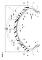
- Fig. 1 shows a cross sectional view of a motorcycle tire (hereinafter it may simply be referred as "the tire") 1 in accordance with the present invention under the normally inflated unloaded condition.
- the tire 1 in accordance with the present invention comprises a tread portion 2, a pair of sidewall portions 3 extending from axially both ends of the tread portion 2, a pair of bead portion 4 each with a bead core 5 therein, a carcass 6 extending between bead cores 5 through the tread portion 2 and sidewall portions 3, a belt layer 7 disposed radially outside the carcass 6 in the tread portion 2 and a tread rubber portion 2G disposed radially outside of the belt layer 7.
- the tread portion 2 has a ground contact surface 2S between a pair of tread edges 2t, 2t which protrudes radially outwardly while curving in a convex arc-like manner so that a wide ground contact area is obtained during turning with a large camber angle.
- Each tread edge 2t is provided at the axially outmost end of the tire to define a tread width Tw which is an axial distance therebetween being a tire maximum width.
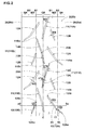
- the tread edges 2t include a first tread edge 2ta and a second tread edge 2tb (shown in Fig. 2 ).
- the carcass 6 includes at least one carcass ply 6A of cords arranged at an angle of from 65 to 90 degrees with respect to the tire equator C in this embodiment.
- the carcass ply 6A comprises a main portion 6a extending between bead cores 5 and a pair of turn-up portions 6b each turned up around the bead core 5 from the axially inside to the outside of the tire.
- organic fiber cords such as rayon, nylon, polyester may be used for the carcass cord.
- a bead apex 8 made of a hard rubber is provided between the main portion 6a and the turned up portion 6b which extends and tapers radially outwardly from the bead core 5.
- the belt layer 7 comprises two belt plies 7A and 7B each having parallel cords arranged at an angle with respect to the tire equator C so that the plies 7A and 7B cross each other.
- the belt cords steel cord and high modulus organic fiber cords such as aramid, rayon can be preferably used.
- the tread rubber portion 2G includes a center portion CR disposed in a center region of the tread portion 2 including the tire equator C, a pair of shoulder portions SH each of which is disposed in each side of the tread edge 2t and a pair of middle portions MD each of which is disposed between the center and shoulder portions CR, SH in each side of the tire equator C.
- the center portion CR, the shoulder portion SH and the middle portion MD are made of different rubber compositions, respectively.
- the center portion CR has a development width W1 in a range of from 28% to 40% of the tread development width TWe on the ground contact surface 2s.
- the center portion has an axial center corresponding to the tire equator C, in this embodiment.
- a ground contact width of the tread portion 2 is about 25% of the tread development width TWe. Accordingly, since the center portion CR has the width W1 larger than the ground contact width above, uneven wear such as step wear at a boundary between the center portion CR and the middle portion SH may be prevented.
- the ground contact width of the tread portion 2 during straight traveling is measured under a normally inflated loaded condition such that the tire 1 is mounted on the standard wheel rim and inflated to the standard pressure and loaded with a standard tire load, as a maximum axial width in the contact patch of the tread portion.
- the standard load means the "maximum load capacity" in JATMA, the “Load Capacity” in ETRTO, and the maximum value given in the above-mentioned table in TRA or the like. In case that an officially approved tire load is not available, a tire load recommended by the tire manufacturer may be applied.
- the tread rubber portion 2G includes a pair of boundaries B1 each of which is between the center portion CR and the middle portion MD, and a pair of boundaries B2 each of which is between the middle portion MD and the shoulder portion SH.
- boundaries B1 and B2 extends from the ground contact surface 2S toward the belt layer 7 with an axially outward inclination.
- the boundaries B1 and B2 may extend along a nominal line perpendicular to the ground contact surface 2S or the belt layer 7. In still another embodiment, the boundaries B1 and B2 may extend with an axially inward inclination.
- center portion CR, middle portion MD and shoulder portion SH satisfy the following relations (1), (2) and (3): E * 1 ⁇ E * 2 ⁇ E * 3 0.9 ⁇ tan ⁇ ⁇ 1 / tan ⁇ ⁇ 2 ⁇ 1.1 and 0.9 ⁇ tan ⁇ ⁇ 2 / tan ⁇ ⁇ 3 ⁇ 1.1
- E*1, E*2 and E*3 are complex elastic moduli of the center portion CR, middle portion MD and shoulder portion SH, respectively and tan 81, tan ⁇ 2 and tan ⁇ 3 are loss tangent of the center portion CR, middle portion MD and shoulder portion SH, respectively.
- E* is a complex elastic modulus
- E" is a loss modulus
- LC is a loss compliance
- tan ⁇ is a loss tangent
- E' is a storage modulus.
- a complex elastic modulus (E*) of a rubber portion may be increased toward the shoulder portion SH from center portion CR by decreasing the loss compliance (LC) while maintaining the loss tangent (tan ⁇ ) and the storage modulus E'.
- the tire 1 in accordance with the present embodiment has the tread rubber portion 2G having gradually increasing complex elastic moduli from the center portion SH toward the shoulder portion SH, turning stability of the tire may improve. Meanwhile, since loss tangent tan 81 to tan ⁇ 2 of the tread rubber portion 2G are substantially the same from the center portion SH toward the shoulder portion SH, transient characteristic between the straight traveling and turning may also improve. Additionally, since a center region of the tread rubber portion 2G has low rigidity, such a tire absorbs vibrations from the ground so that the ride comfort is improved.
- the ratio tan ⁇ 1/tan ⁇ 2 when the ratio tan ⁇ 1/tan ⁇ 2 is less than 0.9, the transient characteristic and uneven wear resistance of the tread rubber portion 2G may deteriorate due to large difference in grip performance between the center portion CR and the middle portion MD.
- the ratio tan ⁇ 1/tan ⁇ 2 is more than 1.1, turning stability of the tire may deteriorate due to low grip performance of the middle portion MD.
- the ratio tan ⁇ 1/tan ⁇ 2 is in a range of from not less than 0.95, and not more than 1.05.
- the ratio tan82/tan83 is preferably in a range of from not less than 0.95, and not more than 1.05.
- the loss tangent tan 81 of the center portion CR is preferably in a range of from 0.20 to 0.24.
- the loss tangent tan 81 of the center portion CR is less than 2.0, grip performance thereof may deteriorate.
- the loss tangent tan 81 is more than 2.4, wear resistance of the center portion CR may deteriorate.
- the loss tangent tan 81 of the center portion CR is in a range of from 0.21 to 0.23.
- the complex elastic modulus E*1 of the center portion CR is in a range of from 4.0 to 5.5 MPa.
- the complex elastic modulus E*1 is more than 5.5MPa, ride comfort of the tire may deteriorate due to the center portion CR with high rigidity.
- the complex elastic modulus E*1 is less than 4.0MPa, turning stability of the tire may deteriorate.
- the complex elastic modulus E*1 is in a range of from 4.3 to 4.9 MPa.
- the ratio (E*2-E*1)/E*1 of the difference (E*2-E*1) between complex elastic moduli E*2 and E*1 to the complex elastic modulus E*1 is in a range of from 1% to 20%.
- the ratio (E*2-E*1)/E*1 is less than 1%, turning stability is liable to deteriorates.
- the ratio (E*2-E*1)/E*1 is more than 20%, transient characteristic of the tire is liable to deteriorates.
- the ratio (E*2-E*1)/E*1 is in a range of from 5% to 7%.
- the ratio (E*3-E*2)/E*2 of the difference (E*3-E*2) between complex elastic moduli E*3 and E*2 to the complex elastic modulus E*2 is preferably in a range of not less than 1%, more preferably not less than 5%, but preferably not more than 20%, more preferably not more than 7%.
- the tread portion 2 is provided with a plurality of center inclined grooves 11 and a plurality of outer inclined grooves 12 in each side of the tire equator C.
- the center inclined grooves 11 include: a plurality of first center inclined grooves 11A which extend from the vicinity of the tire equator C toward the first tread edge 2ta; and a plurality of second center inclined grooves 11B which extend from the vicinity of the tire equator C toward the second tread edge 2tb.
- the first inclined grooves 11A and the second inclined grooves 11B are alternately arranged in the circumferential direction of the tire.
- Each first center inclined groove 11A has an axially inner end 11Ai which positions in the side of the second tread edge 2tb than the tire equator C. Additionally, the first center inclined groove 11A has an axially outer end 11Ao which positions within the center portion CR.
- Each second center inclined groove 11B has an axially inner end 11Bi which positions in the side of the first tread edge 2ta than the tire equator C. Additionally, the second center inclined groove 11B has an axially outer end 11Bo which positions within the center portion CR.
- the first and second center inclined grooves 11A, 11B may improve drainage performance during straight traveling while maintaining rigidity of the middle and shoulder portions MD, SH.
- maximum groove widths W2 of the center inclined grooves 11 are in a range of from 2% to 4% of the tread development width TWe.
- Maximum groove depths d2 (shown in Fig. 1 ) of the center inclined grooves 11 are preferably in a range of from 2% to 5% of the tread development width TWe.
- Each first center inclined grooves 11A comprises an axially inner part 13A which extends from the inner end 11Ai with an angle ⁇ 1a in a range of from 8 to 12 degrees with respect to the tire circumferential direction and an axially outer part 14A having an angle ⁇ 1b in a range of from 18 to 22 degrees with respect to the tire circumferential direction.
- the inner part 13A and the outer part 13B are connected through an inflection point 20A.
- each second center inclined grooves 11B comprises an axially inner part 13B having the angle ⁇ 1a, an axially outer part 14B having the angle ⁇ 1b and an inflection point 20B.
- the tread portion 2 Since the first and second center inclined grooves 11 have angles gradually increasing toward middle portion MD from the tire equator C, the tread portion 2 has enhanced torsional rigidity so that the transient characteristic between straight traveling and turning improves.
- the outer inclined groove 12 is provided between circumferentially adjacent center inclined grooves 11, 11 so as to incline an opposite direction to the center inclined grooves 11.
- the outer inclined grooves 12 include a first outer inclined groove 12A which has an axially inner end 12Ai positioned within the center portion CR and an axially outer end 12Ao positioned within the shoulder portion SH and a second outer inclined groove 12B which has axially inner and outer ends 12Bi, 12Bo both positioned within the middle portion MD.
- Each first outer inclined grooves 12A comprises an axially inner part 15 which extends from the inner end 12Ai toward axially outside of the tire with an angle ⁇ 2a in a range of from 30 to 40 degrees with respect to the tire circumferential direction and an axially outer part 16 having an angle ⁇ 2b in a range of from 50 to 60 degrees with respect to the tire circumferential direction.
- the inner part 15 and the outer part 16 are connected through an inflection point 17.
- the inflection point 17 locates in the vicinity of the boundary B2 between the middle portion Md and the shoulder portion SH.
- the first outer inclined groove 12A improves drainage performance of the tire due to cover a wide range from the center portion CR to the shoulder portion SH. Additionally, since the first outer inclined groove 12 has a large angle in the middle and shoulder portions MD and SH, the tread portion 2 further has enhanced torsional rigidity so that the transient characteristic improves.
- the maximum groove width W3 and the maximum groove depth D3 (shown in Fig. 1 ) of the first outer inclined groove 12A are set in the same range with the maximum groove width W2 and the maximum groove depth D2 of the inner inclined groove 11.
- the second outer inclined groove 12B has an angle ⁇ 3 in a range of from 15 to 25 degrees with respect to the tire circumferential direction to improve the drainage performance of the tire.
- the maximum groove width W4 and the maximum groove depth D4 (shown in Fig. 1 ) of the second outer inclined groove 12B are set in the same range with the maximum groove width W2 and the maximum groove depth D2 of the inner inclined groove 11.
- the tread portion 2 satisfies the following relation (3): LF ⁇ 1 ⁇ LF ⁇ 2 ⁇ LF ⁇ 3
- LF1, LF2 and LF3 are land ratios of the center portion, middle portion and shoulder portion, respectively.
- the "land ratio” is a ratio of a tread surface area which contacts on the ground to a gross surface area of the tread portion in a condition that whole grooves are omitted in a defined region of the tread portion.
- the tire 1 in accordance with the present invention has the tread portion 2 having rigidity gradually increasing toward the shoulder portion SH from the center portion CR, the turning transient characteristic and turning stability thereof are improved. Additionally, the drainage performance of the tire in straight traveling may be improved due to small land ratio LF1.
- the ratio LF2/LF1 of the land ratio LF2 on the middle portion MD to the land ratio LF1 on the center portion CR is preferably in a range of from 101% to 106%. More preferably, the ratio LF2/LF1 is in a range of from 102% to 105%.
- the ratio LF3/LF2 of the land ratio LF3 on the shoulder portion SH to the land ratio LF2 on the middle portion MD is preferably set in the same range with the ratio LF2/LF1.
- Fig. 3 is a cross sectional view of a motorcycle tire 1 showing another embodiment of the present invention.
- the tire 1 has the tread rubber 2G comprising the middle portion Md which includes an inner middle portion MDi disposed in the side of the center portion CR and an outer middle portion MDo disposed on the side of the shoulder portion SH.
- the middle portion MD has the following relations (4) and (5): E * 2 ⁇ i ⁇ E * 2 ⁇ o and 0.9 ⁇ tan ⁇ ⁇ 2 ⁇ i / tan ⁇ ⁇ 2 ⁇ o ⁇ 1.1
- E*2i and E*2o are complex elastic moduli of the inner middle portion MDi and the outer middle portion MDo, respectively, and tan ⁇ 2i and tan ⁇ 2o are loss tangent of the inner and outer middle portions MDi, MDo, respectively.
- the tire in accordance with the present invention has the tread rubber 2G having complex elastic moduli further smoothly increasing toward the shoulder portion SH from the center portion CR while substantially maintaining loss tangent thereof, turning stability and transient characteristic of the tire may further improve.
- the ratio (E*2o-E*2i)/E*2i of the difference (E*2o-E*2i) between the complex elastic modulus E*2o of the outer middle portion MDo and the complex modulus E*2i of the inner middle portion MDi to the complex elastic modulus E*2i is preferably set in the same range with the above-mentioned ratios (E*2-E*1)/E*1 and (E*3-E*2)/E*2.
- the land ratio LF2i of the inner middle portion MDi and the land ratio LF2o of the outer middle portion MDo have the following relation (9): LF ⁇ 2 ⁇ i ⁇ LF ⁇ 2 ⁇ o
- the tire 1 in accordance with the embodiment has the boundary B3 between the inner middle portion MDi and the outer middle portion MDo which inclines from the ground contact surface 2s of the tread portion 2 toward the belt layer 7 with an inclination toward axially inwardly of the tire. Since rubber property of the tread rubber portion 2G further gradually changes, transient characteristic of the tire between straight traveling and turning may improve.
- SBR Styrene-butadiene rubber
- Carbon black N110 available from showa Cabot Corp.
- Process oil DIANAPROCESS PS32 available from Idemitsu Kosan Co., Ltd.
- Antioxidant ANTIGEN6C (N-(1,3-dimethylbutyl)-N'-phenyl-p-phenylenediamine) available from Sumitomo Chemical Company, Limited
- Stearic acid Stearic acid "Tsubaki” available from NOF Corporation
- Zinc oxide Zinc oxide #2 available from Mitsui Mining & Smelting Co., Ltd.
- Vulcanization accelerator (1) NOCCELER NS (N-tert-butyl-2-benzothiazolylsulfeneamide) available from ouchi shinko Chemical Industrial CO., LTD.
- vulcanization accelerator (2) "SOKUSITOL-D" available from Sumitomo Chemical Company, Limited
- Each test tire was installed in the motorcycle having a 600cc displacement.
- a test driver drove the motorcycle on a test course having a dry asphalt road, and evaluated turning stability, transient characteristic during turning and ride comfort by his feeling.
- Each test result was shown as a score of a maximum 10. The greater the score, the better the performance is.
- test driver drove the motorcycle on a test course having a wet asphalt road, and evaluated drainage performance of the tire by his feeling. Each test result was shown as a score of a maximum 10. The greater the score, the better the performance is.
- test motorcycle above was driven on a dry asphalt road for 1,000 km, and then each wear amount of center, middle and shoulder portions was measured at three points in the tire circumferential direction in each portion, and the average wear amount in each portion was evaluated.
- index of 100 representing a value in ref. 1. The larger the value, the better the performance is.
- Example tires in accordance with the present invention can be effectively improved turning stability as well as ride comfort.
- Example tire can be also effectively improved turning stability as well as ride comfort.
Landscapes
- Engineering & Computer Science (AREA)
- Mechanical Engineering (AREA)
- Tires In General (AREA)
Abstract
E*1 < E*2 < E*3,
0,9 ≤ tanδ1/tanδ2 ≤ 1.1, and
0,9 ≤ tanδ2/tanδ3 ≤ 1.1,
wherein E*1, E*2 and E*3 are complex elastic moduli of the center, middle and shoulder portions respectively, and tanδ1, tanδ2 and tanδ3 are loss tangent of the center, middle and shoulder portions respectively.
Description
- The present invention relates to a motorcycle tire capable of improving turning stability and ride comfort.
- Typically, a motorcycle tire has a tread portion having a tread outer surface which protrudes radially outwardly of the tire in a convex arc-like manner in order to obtain a sufficient ground contact area of the tread portion when a motorcycle is turning with a large camber angle.
-
JP-2007-131112-A1 - However, since the shoulder portion with large loss tangent tends to have low rigidity, turning stability of the tire is liable to decrease. Additionally, since the center portion of the tread rubber with high rigidity is difficult to sufficiently absorb vibrations from the ground when straight running, such a tire tends to deteriorate ride comfort.
- The present invention has been worked out in light of the circumstances described above, and has a main object of providing a motorcycle tire capable of improving a turning stability and ride comfort.
- In accordance with the present invention, there is provided a motorcycle tire comprising a tread portion having a tread outer surface between tread edges, the tread outer surface protruding radially outwardly of the tire in a convex arc-like manner, the tread portion including a tread rubber portion, the tread rubber portion including a center portion disposed in a center region of the tread portion including a tire equator, a pair of shoulder portions each of which is disposed in each side of the tread edge and a pair of middle portions each of which is disposed between the center and shoulder portions in each side of the tire equator, and the center, middle and shoulder portions satisfy the following relations:


and
wherein E*1, E*2 and E*3 are complex elastic moduli of the center portion, middle portion and shoulder portion respectively, and tanδ1, tanδ2 and tanδ3 are loss tangent of the center portion, middle portion and shoulder portion respectively. - In this application including specification and claims, various dimensions, positions and the like of the tire refer to those under a normally inflated unloaded condition of the tire unless otherwise noted.
- The normally inflated unloaded condition is such that the ti re is mounted on a standard wheel rim (not shown) and is inflated to a standard pressure but loaded with no tire load.
- The standard wheel rim means a wheel rim officially approved or recommended for the tire by standards organizations, the standard wheel rim is the "standard rim" specified in JATMA, the "Measuring Rim" in ETRTO, the "Design Rim" in TRA or the like, for example.
- The standard pressure means the "maximum air pressure" in JATMA, the "Inflation Pressure" in ETRTO, and the maximum pressure given in the "Tire Load Limits at various Cold Inflation Pressures" table in TRA or the like.
-
-
Fig. 1 is a cross sectional view of a motorcycle tire showing an embodiment of the present invention. -
Fig. 2 is a development view of a tread portion of the tire ofFig. 1 . -
Fig. 3 is a cross sectional view of a motorcycle tire showing another embodiment of the present invention. - An embodiment of the present invention will be explained below with reference to the accompanying drawings.
-
Fig. 1 shows a cross sectional view of a motorcycle tire (hereinafter it may simply be referred as "the tire") 1 in accordance with the present invention under the normally inflated unloaded condition. - Referring to
Fig. 1 , the tire 1 in accordance with the present invention comprises atread portion 2, a pair ofsidewall portions 3 extending from axially both ends of thetread portion 2, a pair ofbead portion 4 each with abead core 5 therein, acarcass 6 extending betweenbead cores 5 through thetread portion 2 andsidewall portions 3, a belt layer 7 disposed radially outside thecarcass 6 in thetread portion 2 and atread rubber portion 2G disposed radially outside of the belt layer 7. - The
tread portion 2 has aground contact surface 2S between a pair oftread edges tread edge 2t is provided at the axially outmost end of the tire to define a tread width Tw which is an axial distance therebetween being a tire maximum width. Thetread edges 2t include a first tread edge 2ta and a second tread edge 2tb (shown inFig. 2 ). - The
carcass 6 includes at least onecarcass ply 6A of cords arranged at an angle of from 65 to 90 degrees with respect to the tire equator C in this embodiment. Thecarcass ply 6A comprises amain portion 6a extending betweenbead cores 5 and a pair of turn-upportions 6b each turned up around thebead core 5 from the axially inside to the outside of the tire. - Preferably, organic fiber cords such as rayon, nylon, polyester may be used for the carcass cord. A
bead apex 8 made of a hard rubber is provided between themain portion 6a and the turned upportion 6b which extends and tapers radially outwardly from thebead core 5. - In this embodiment, the belt layer 7 comprises two
belt plies plies - The
tread rubber portion 2G includes a center portion CR disposed in a center region of thetread portion 2 including the tire equator C, a pair of shoulder portions SH each of which is disposed in each side of thetread edge 2t and a pair of middle portions MD each of which is disposed between the center and shoulder portions CR, SH in each side of the tire equator C. The center portion CR, the shoulder portion SH and the middle portion MD are made of different rubber compositions, respectively. - In this embodiment, the center portion CR has a development width W1 in a range of from 28% to 40% of the tread development width TWe on the ground contact surface 2s. The center portion has an axial center corresponding to the tire equator C, in this embodiment. Typically, when the tire is traveling in straight, a ground contact width of the
tread portion 2 is about 25% of the tread development width TWe. Accordingly, since the center portion CR has the width W1 larger than the ground contact width above, uneven wear such as step wear at a boundary between the center portion CR and the middle portion SH may be prevented. - Here, the ground contact width of the
tread portion 2 during straight traveling is measured under a normally inflated loaded condition such that the tire 1 is mounted on the standard wheel rim and inflated to the standard pressure and loaded with a standard tire load, as a maximum axial width in the contact patch of the tread portion. - The standard load means the "maximum load capacity" in JATMA, the "Load Capacity" in ETRTO, and the maximum value given in the above-mentioned table in TRA or the like. In case that an officially approved tire load is not available, a tire load recommended by the tire manufacturer may be applied.
- The
tread rubber portion 2G includes a pair of boundaries B1 each of which is between the center portion CR and the middle portion MD, and a pair of boundaries B2 each of which is between the middle portion MD and the shoulder portion SH. Each of boundaries B1 and B2 extends from theground contact surface 2S toward the belt layer 7 with an axially outward inclination. - Thus, since rubber property of the
tread rubber portion 2G gradually changes, transient characteristic of the tire between straight traveling and turning may improve. In another aspect, the boundaries B1 and B2 may extend along a nominal line perpendicular to theground contact surface 2S or the belt layer 7. In still another embodiment, the boundaries B1 and B2 may extend with an axially inward inclination. - Additionally, the center portion CR, middle portion MD and shoulder portion SH satisfy the following relations (1), (2) and (3):


and
- Where, E*1, E*2 and E*3 are complex elastic moduli of the center portion CR, middle portion MD and shoulder portion SH, respectively and tan 81, tan δ2 and tan δ3 are loss tangent of the center portion CR, middle portion MD and shoulder portion SH, respectively.
- Here, the complex elastic modulus E* and loss tangent (tan δ) were measured with a viscoelastic spectrometer made by IWAMOTO SEISAKUSYO according to the Japanese Industrial Standard JIS-K-6394. The measuring conditions are as follows:
- Temperature: 70 degrees C;
- Deformation mode: tensile;
- Frequency: 10 Hz;
- Amplitude: plus/
minus 2%; and - Initial elongation: 10 %.
- Generally, the complex elastic modulus E* and loss tangent (tan δ) are calculated using the following expressions (6) and (7), respectively:

and
- Here, E* is a complex elastic modulus, E" is a loss modulus, LC is a loss compliance, tan δ is a loss tangent and E' is a storage modulus. These parameters are measured according to the same condition with the loss tangent, and the loss compliance is given by the expression (6). These expressions (6) and (7) satisfy the following relation (8):

- Accordingly, a complex elastic modulus (E*) of a rubber portion may be increased toward the shoulder portion SH from center portion CR by decreasing the loss compliance (LC) while maintaining the loss tangent (tan δ) and the storage modulus E'.
- Since the tire 1 in accordance with the present embodiment has the
tread rubber portion 2G having gradually increasing complex elastic moduli from the center portion SH toward the shoulder portion SH, turning stability of the tire may improve. Meanwhile, since loss tangent tan 81 to tan δ2 of thetread rubber portion 2G are substantially the same from the center portion SH toward the shoulder portion SH, transient characteristic between the straight traveling and turning may also improve. Additionally, since a center region of thetread rubber portion 2G has low rigidity, such a tire absorbs vibrations from the ground so that the ride comfort is improved. - Here, when the ratio tanδ1/tanδ2 is less than 0.9, the transient characteristic and uneven wear resistance of the
tread rubber portion 2G may deteriorate due to large difference in grip performance between the center portion CR and the middle portion MD. When the ratio tanδ1/tanδ2 is more than 1.1, turning stability of the tire may deteriorate due to low grip performance of the middle portion MD. Preferably, the ratio tanδ1/tanδ2 is in a range of from not less than 0.95, and not more than 1.05. - From the same point of view above, the ratio tan82/tan83 is preferably in a range of from not less than 0.95, and not more than 1.05.
- In order to further improve the effect above, the loss tangent tan 81 of the center portion CR is preferably in a range of from 0.20 to 0.24. When the loss tangent tan 81 of the center portion CR is less than 2.0, grip performance thereof may deteriorate. When the loss tangent tan 81 is more than 2.4, wear resistance of the center portion CR may deteriorate. Still further preferably, the loss tangent tan 81 of the center portion CR is in a range of from 0.21 to 0.23.
- Preferably, the complex elastic modulus E*1 of the center portion CR is in a range of from 4.0 to 5.5 MPa. When the complex elastic modulus E*1 is more than 5.5MPa, ride comfort of the tire may deteriorate due to the center portion CR with high rigidity. When the complex elastic modulus E*1 is less than 4.0MPa, turning stability of the tire may deteriorate. still further preferably, the complex elastic modulus E*1 is in a range of from 4.3 to 4.9 MPa.
- Preferably, the ratio (E*2-E*1)/E*1 of the difference (E*2-E*1) between complex elastic moduli E*2 and E*1 to the complex elastic modulus E*1 is in a range of from 1% to 20%. When the ratio (E*2-E*1)/E*1 is less than 1%, turning stability is liable to deteriorates. When the ratio (E*2-E*1)/E*1 is more than 20%, transient characteristic of the tire is liable to deteriorates. Still further preferably, the ratio (E*2-E*1)/E*1 is in a range of from 5% to 7%.
- From the same point of view, the ratio (E*3-E*2)/E*2 of the difference (E*3-E*2) between complex elastic moduli E*3 and E*2 to the complex elastic modulus E*2 is preferably in a range of not less than 1%, more preferably not less than 5%, but preferably not more than 20%, more preferably not more than 7%.
- Referring to
Fig. 2 , thetread portion 2 is provided with a plurality of center inclinedgrooves 11 and a plurality of outerinclined grooves 12 in each side of the tire equator C. - The center inclined
grooves 11 include: a plurality of first center inclinedgrooves 11A which extend from the vicinity of the tire equator C toward the first tread edge 2ta; and a plurality of second center inclinedgrooves 11B which extend from the vicinity of the tire equator C toward the second tread edge 2tb. The firstinclined grooves 11A and the secondinclined grooves 11B are alternately arranged in the circumferential direction of the tire. - Each first center inclined
groove 11A has an axially inner end 11Ai which positions in the side of the second tread edge 2tb than the tire equator C. Additionally, the first center inclinedgroove 11A has an axially outer end 11Ao which positions within the center portion CR. - Each second center inclined
groove 11B has an axially inner end 11Bi which positions in the side of the first tread edge 2ta than the tire equator C. Additionally, the second center inclinedgroove 11B has an axially outer end 11Bo which positions within the center portion CR. - The first and second center inclined
grooves grooves 11 are in a range of from 2% to 4% of the tread development width TWe.Maximum groove depths d2 (shown inFig. 1 ) of the center inclinedgrooves 11 are preferably in a range of from 2% to 5% of the tread development width TWe. - Each first center inclined
grooves 11A comprises an axiallyinner part 13A which extends from the inner end 11Ai with an angle α1a in a range of from 8 to 12 degrees with respect to the tire circumferential direction and an axiallyouter part 14A having an angle α1b in a range of from 18 to 22 degrees with respect to the tire circumferential direction. Theinner part 13A and theouter part 13B are connected through aninflection point 20A. similarly, each second center inclinedgrooves 11B comprises an axiallyinner part 13B having the angle α1a, an axiallyouter part 14B having the angle α1b and aninflection point 20B. - Since the first and second center inclined
grooves 11 have angles gradually increasing toward middle portion MD from the tire equator C, thetread portion 2 has enhanced torsional rigidity so that the transient characteristic between straight traveling and turning improves. - In each side of the tire equator C, the outer
inclined groove 12 is provided between circumferentially adjacent center inclinedgrooves grooves 11. - In each side of the tire equator C, the outer
inclined grooves 12 include a first outerinclined groove 12A which has an axially inner end 12Ai positioned within the center portion CR and an axially outer end 12Ao positioned within the shoulder portion SH and a second outerinclined groove 12B which has axially inner and outer ends 12Bi, 12Bo both positioned within the middle portion MD. - Each first outer
inclined grooves 12A comprises an axiallyinner part 15 which extends from the inner end 12Ai toward axially outside of the tire with an angle α2a in a range of from 30 to 40 degrees with respect to the tire circumferential direction and an axiallyouter part 16 having an angle α2b in a range of from 50 to 60 degrees with respect to the tire circumferential direction. Theinner part 15 and theouter part 16 are connected through aninflection point 17. Theinflection point 17 locates in the vicinity of the boundary B2 between the middle portion Md and the shoulder portion SH. - The first outer
inclined groove 12A improves drainage performance of the tire due to cover a wide range from the center portion CR to the shoulder portion SH. Additionally, since the first outerinclined groove 12 has a large angle in the middle and shoulder portions MD and SH, thetread portion 2 further has enhanced torsional rigidity so that the transient characteristic improves. Preferably, the maximum groove width W3 and the maximum groove depth D3 (shown inFig. 1 ) of the first outerinclined groove 12A are set in the same range with the maximum groove width W2 and the maximum groove depth D2 of the innerinclined groove 11. - The second outer
inclined groove 12B has an angle α3 in a range of from 15 to 25 degrees with respect to the tire circumferential direction to improve the drainage performance of the tire. Preferably, the maximum groove width W4 and the maximum groove depth D4 (shown inFig. 1 ) of the second outerinclined groove 12B are set in the same range with the maximum groove width W2 and the maximum groove depth D2 of the innerinclined groove 11. - One aspect of the present invention, the
tread portion 2 satisfies the following relation (3):
- Here, LF1, LF2 and LF3 are land ratios of the center portion, middle portion and shoulder portion, respectively. The "land ratio" is a ratio of a tread surface area which contacts on the ground to a gross surface area of the tread portion in a condition that whole grooves are omitted in a defined region of the tread portion.
- Since the tire 1 in accordance with the present invention has the
tread portion 2 having rigidity gradually increasing toward the shoulder portion SH from the center portion CR, the turning transient characteristic and turning stability thereof are improved. Additionally, the drainage performance of the tire in straight traveling may be improved due to small land ratio LF1. - In order to further improve the advantages above, the ratio LF2/LF1 of the land ratio LF2 on the middle portion MD to the land ratio LF1 on the center portion CR is preferably in a range of from 101% to 106%. More preferably, the ratio LF2/LF1 is in a range of from 102% to 105%.
- Similarly, the ratio LF3/LF2 of the land ratio LF3 on the shoulder portion SH to the land ratio LF2 on the middle portion MD is preferably set in the same range with the ratio LF2/LF1.
-
Fig. 3 is a cross sectional view of a motorcycle tire 1 showing another embodiment of the present invention. Referring toFig. 3 , the tire 1 has thetread rubber 2G comprising the middle portion Md which includes an inner middle portion MDi disposed in the side of the center portion CR and an outer middle portion MDo disposed on the side of the shoulder portion SH. - In this aspect, the middle portion MD has the following relations (4) and (5):

and
- Here, E*2i and E*2o are complex elastic moduli of the inner middle portion MDi and the outer middle portion MDo, respectively, and tan δ2i and tan δ2o are loss tangent of the inner and outer middle portions MDi, MDo, respectively.
- Since the tire in accordance with the present invention has the
tread rubber 2G having complex elastic moduli further smoothly increasing toward the shoulder portion SH from the center portion CR while substantially maintaining loss tangent thereof, turning stability and transient characteristic of the tire may further improve. - The ratio (E*2o-E*2i)/E*2i of the difference (E*2o-E*2i) between the complex elastic modulus E*2o of the outer middle portion MDo and the complex modulus E*2i of the inner middle portion MDi to the complex elastic modulus E*2i is preferably set in the same range with the above-mentioned ratios (E*2-E*1)/E*1 and (E*3-E*2)/E*2.
- Preferably, the land ratio LF2i of the inner middle portion MDi and the land ratio LF2o of the outer middle portion MDo have the following relation (9):

- Thus, since rigidity of the
tread rubber portion 2G further smoothly increases toward the shoulder portion SH from the crown portion CR, transient characteristic of the tire still further may improve. - The tire 1 in accordance with the embodiment has the boundary B3 between the inner middle portion MDi and the outer middle portion MDo which inclines from the ground contact surface 2s of the
tread portion 2 toward the belt layer 7 with an inclination toward axially inwardly of the tire. Since rubber property of thetread rubber portion 2G further gradually changes, transient characteristic of the tire between straight traveling and turning may improve. - The present invention is more specifically described and explained by means of the following Examples and References. It is to be understood that the present invention is not limited to these Examples.
- Motorcycle tires each having a basic structure of
Fig. 1 and a basic tread pattern ofFig. 2 except for details shown in Table 1 were made and tested. Major common specifics of tires are as follows. - Tire size
- Front: 120/90ZR17
- Rear: 180/55ZR17
- Rim size
- Front: MT3.50x17
- Rear: MT5.50x17
- Internal pressure:
- Front: 250kPa
- Rear: 290kPa
- Tread development width TWe: 225mm
- Tread width TW: 180mm
- Development width of center portion W1: 45mm
- Ratio W1/TWe: 20%
- various chemicals used in each rubber composition of center, middle and shoulder portions are shown in Table 2. Major common specifics are as follows.
Styrene-butadiene rubber (SBR): T4850 available from Asahi KASEI Corp.
Carbon black: N110 available from showa Cabot Corp.
Process oil: DIANAPROCESS PS32 available from Idemitsu Kosan Co., Ltd.
Antioxidant: ANTIGEN6C (N-(1,3-dimethylbutyl)-N'-phenyl-p-phenylenediamine) available from Sumitomo Chemical Company, Limited
Stearic acid: Stearic acid "Tsubaki" available from NOF Corporation
Zinc oxide:Zinc oxide # 2 available from Mitsui Mining & Smelting Co., Ltd.
Sulfur: Powder sulfur available from Karuizawa Sulfur Co., Ltd. Silica: VN3 available from Degussa Co.
Silane coupling agent: Si75 available from Degussa Co. Wax: SUNNOC N available from Ouchi Shinko Chemical Industrial CO., LTD.
Vulcanization accelerator (1): NOCCELER NS (N-tert-butyl-2-benzothiazolylsulfeneamide) available from ouchi shinko Chemical Industrial CO., LTD.
vulcanization accelerator (2): "SOKUSITOL-D" available from Sumitomo Chemical Company, Limited - Test methods are as follows.
- Each test tire was installed in the motorcycle having a 600cc displacement. A test driver drove the motorcycle on a test course having a dry asphalt road, and evaluated turning stability, transient characteristic during turning and ride comfort by his feeling. Each test result was shown as a score of a maximum 10. The greater the score, the better the performance is.
- A test driver drove the motorcycle on a test course having a wet asphalt road, and evaluated drainage performance of the tire by his feeling. Each test result was shown as a score of a maximum 10. The greater the score, the better the performance is.
- The test motorcycle above was driven on a dry asphalt road for 1,000 km, and then each wear amount of center, middle and shoulder portions was measured at three points in the tire circumferential direction in each portion, and the average wear amount in each portion was evaluated. The results are shown with an index of 100 representing a value in ref. 1. The larger the value, the better the performance is.
- Test results are shown in Table 1
Table 1 Ref.1 Ref.2 Ex.1 Ex.2 Ex.3 Ref.3 Ex.4 Ex.5 Ref. 4 Ex.6 Ex.7 Center portion composition - No.1 No. 3 No.1 No.6 No.3 No.3 No 3No.3 No.3 No.3 Middle portion composition - No. 2 No. 2 No.4 No.7 No.9 No.11 No.13 No.15 No.15 No.2 Shoulder portion composition - No. 3 No.1 No.5 No.8 No.10 No.12 No.14 No.16 No.14 No.1 Complex elastic modulus E*1 (MPa) - 4 3.6 4 5.5 3.6 3.6 3.6 3.6 3.6 3.6 Complex elastic modulus E*2 (MPa) - 3.8 3.8 4.2 5. 7 3.8 3.8 3.8 3.8 3.8 3.8 Complex elastic modulus E*3 (MPa) - 3.6 4 4.5 5.9 4 4 4 4 4 4 Ratio (E*2-E*1) /E*1 (%) - -5 5.6 5 3.6 5.6 5.6 5.6 5.6 5.6 5.6 Ratio (E*3-E*2) /E*2 (%) - -5.3 5.3 7.1 3.5 5.3 5.3 5.3 5.3 5.3 5.3 Loss tangent tan δ1 - 0.24 0.24 0.24 0.24 0.24 0.24 0.24 0.24 0.2 0.24 Loss tangent tan δ2 - 0.24 0.24 0.24 0.24 0.3 0.26 0.22 0.2 0.2 0.24 Loss tangent tan δ3 - 0.24 0.24 0.24 0.24 0.36 0.29 0.2 0.17 0.2 0.24 tan δ1/tan δ2 - 1 1 1 1 0.8 0.9 1.1 1.2 1 1 tan δ2/tan δ3 - 1 1 1 1 0.8 0.9 1.1 1.2 1 1 Land ratio LF1 (%) - 85 85 85 85 85 85 85 85 85 88 Land ratio LF2 (%) - 88 88 88 88 88 88 88 88 88 88 Land ratio LF3 (%) - 91 91 91 91 91 91 91 91 91 88 Turning stability (Score) 5 5 9 10 10 9 9 8 6 7 7 Transient characteristic (Score) 10 8 8 8 8 6 7 8 8 8 6 Ride comfort (Score) 5 5 10 5 3 10 10 10 10 10 10 Drainage performance (Index) 100 100 100 100 100 100 100 100 100 100 100 Uneven wear resistance (Index) 100 100 110 110 110 70 100 110 110 110 110 Table 2 Composition No. 1 2 3 4 5 6 7 8 9 10 11 12 13 14 15 16 SBR 150 150 150 150 150 150 150 150 150 150 150 150 150 150 150 150 Carbon black 70 70 70 70 70 70 70 70 76 72 72 75 68 66 66 63 Silica 30 30 30 30 30 30 30 30 30 30 30 30 30 30 30 30 Silane coupling agent 2.4 2.4 2.4 2.4 2.4 2.4 2.4 2.4 2.4 2.4 2.4 2.4 2.4 2.4 2.4 2.4 Process oil 19 21 23 17 14 4 2 0 28.5 36 23.5 26 18.5 14 12 10 Wax 2 2 2 2 2 2 2 2 2 2 2 2 2 2 2 2 Antioxidant 2.5 2.5 2.5 2.5 2.5 2.5 2.5 2.5 2.5 2.5 2.5 2.5 2.5 2.5 2.5 2.5 Stearic acid 2.5 2.5 2.5 2.5 2.5 2.5 2.5 2.5 2.5 2.5 2.5 2.5 2.5 2.5 2.5 2.5 Zinc oxide 2.5 2.5 2.5 2.5 2.5 2.5 2.5 2.5 2.5 2.5 2.5 2.5 2.5 2.5 2.5 2.5 Sulfur 1.5 1.5 1.5 1.5 1.5 1.5 1.5 1.5 1.5 1.5 1.5 1.5 1.5 1.5 1.5 1.5 Vulcanization accelerator(1) 2.5 2.5 2.5 2.5 2.5 2.5 2.5 2.5 2.5 2.5 2.5 2.5 2.5 2.5 2.5 2.5 Vulcanization accelerator(2) 1 1 1 1 1 1 1 1 1 1 1 1 1 1 1 1 *1) Unit: mass %
*2) SBR contains oil of 50% in mass. - From the test results, it was confirmed that Example tires in accordance with the present invention can be effectively improved turning stability as well as ride comfort.
- Motorcycle tires each having a basic structure of
Fig. 3 and a basic tread pattern ofFig. 2 except for the detail shown in Table 3 were made and tested. Major common specifics of tires are the same with the Comparison Test 1. - Test results are shown in Table 3. From the test results, it was confirmed that Example tire can be also effectively improved turning stability as well as ride comfort.
Table 3 Ref.1 Ex.8 Center portion composition - No. 3 Inner middle portion composition - No. 2 Outer middle portion composition - No.1 Shoulder portion composition - No. 4 Complex elastic modulus E*1(MPa) - 3.6 Complex elastic modulus E*2i(MPa) - 3.8 Complex elastic modulus E*2o(MFa) - 4 Complex elastic modulus E*3(MPa) - 4.2 Ratio (E*2i-E*1)/E*1(%) - 5.6 Ratio (E*2o-E*2i)/E*2i(%) - 5.3 Ratio (E*3-E*2o)/E*2o(%) - 5 Loss tangent tan δ1 - 0.24 Loss tangent tan δ2i - 0.24 Loss tangent tan δ2o - 0.24 Loss tangent tan δ3 - 0.24 tan δ1/tan δ2i - 1 tan δ2i/tan δ2o - 1 tan δ2o/tan δ3 - 1 Land ratio LF1(%) - 85 Land ratio LF2i(%) - 88 Land ratio LF2o(%) - 88 Land ratio LF3(%) - 91 Turning stability (Score) 5 10 Transient characteristic (Score) 5 8 Ride comfort (Score) 5 10 Drainage performance (Index) 100 100 Uneven wear resistance (Index) 100 110
Claims (4)
- A motorcycle tire comprising
a tread portion having a tread outer surface between tread edges, the tread outer surface protruding radially outwardly of the tire in a convex arc-like manner,
the tread portion including a tread rubber portion,
the tread rubber portion including
a center portion disposed in a center region of the tread portion including a tire equator,
a pair of shoulder portions each of which is disposed in each side of the tread edge and
a pair of middle portions each of which is disposed between the center and shoulder portions in each side of the tire equator, and
the center, middle and shoulder portions satisfy the following relations:

and
wherein E*1, E*2 and E*3 are complex elastic moduli of the center portion, middle portion and shoulder portion respectively, and tanδ1, tanδ2 and tanδ3 are loss tangent of the center portion, middle portion and shoulder portion respectively. - The tire according to claim 1, wherein
the complex elastic modulus of the center portion is in a range of from 4.0 to 5.5 MPa, and
the loss tangent of the center portion is in a range of from 0.20 to 0.24. - The tire according to claim 1, wherein
the tread portion satisfies the following relation:
wherein LF1, LF2 and LF3 are land ratios each on the center portion, middle portion and shoulder portion respectively. - The tire according to claim 1, wherein
the middle portion includes an inner middle portion disposed in the side of the center portion and an outer portion disposed in the side of the shoulder portion, and
the middle portion has the following relation:
and
wherein E*2i and E*2o are complex elastic moduli of the inner middle portion and the outer middle portion respectively, and tanδ2i and tanδ2o are loss tangent of the inner middle and outer middle portion respectively.
Applications Claiming Priority (1)
| Application Number | Priority Date | Filing Date | Title |
|---|---|---|---|
| JP2012106953A JP5711691B2 (en) | 2012-05-08 | 2012-05-08 | Motorcycle tires |
Publications (2)
| Publication Number | Publication Date |
|---|---|
| EP2662226A1 true EP2662226A1 (en) | 2013-11-13 |
| EP2662226B1 EP2662226B1 (en) | 2016-03-23 |
Family
ID=48013815
Family Applications (1)
| Application Number | Title | Priority Date | Filing Date |
|---|---|---|---|
| EP13161407.5A Not-in-force EP2662226B1 (en) | 2012-05-08 | 2013-03-27 | Motorcycle tire |
Country Status (4)
| Country | Link |
|---|---|
| EP (1) | EP2662226B1 (en) |
| JP (1) | JP5711691B2 (en) |
| AU (1) | AU2013201982B2 (en) |
| RU (1) | RU2617855C2 (en) |
Cited By (7)
| Publication number | Priority date | Publication date | Assignee | Title |
|---|---|---|---|---|
| JP2017030506A (en) * | 2015-07-31 | 2017-02-09 | 株式会社ブリヂストン | Motorcycle tires |
| WO2019082012A1 (en) * | 2017-10-26 | 2019-05-02 | Pirelli Tyre S.P.A. | Motorcycle tyre |
| EP3620309A4 (en) * | 2017-05-02 | 2020-12-09 | Bridgestone Corporation | Tire for two-wheeled vehicle |
| CN115384236A (en) * | 2021-05-19 | 2022-11-25 | 住友橡胶工业株式会社 | Tire for motorcycle |
| IT202200010961A1 (en) | 2022-05-25 | 2023-11-25 | Pirelli | Tire for motorcycle wheels |
| IT202200023889A1 (en) | 2022-11-21 | 2024-05-21 | Pirelli | Motorcycle front tire |
| EP4663430A1 (en) * | 2024-06-12 | 2025-12-17 | Sumitomo Rubber Industries, Ltd. | Motorcycle tire and motorcycle tire set |
Families Citing this family (7)
| Publication number | Priority date | Publication date | Assignee | Title |
|---|---|---|---|---|
| JP6085286B2 (en) * | 2014-12-06 | 2017-02-22 | 住友ゴム工業株式会社 | Motorcycle tires |
| JP6801500B2 (en) * | 2017-02-22 | 2020-12-16 | 住友ゴム工業株式会社 | Motorcycle tires |
| JP6911496B2 (en) * | 2017-05-01 | 2021-07-28 | 住友ゴム工業株式会社 | Motorcycle tires |
| JP6820013B2 (en) * | 2017-05-02 | 2021-01-27 | 株式会社ブリヂストン | Motorcycle tires |
| JP7040046B2 (en) * | 2018-01-25 | 2022-03-23 | 住友ゴム工業株式会社 | Motorcycle tires |
| JP2025067214A (en) * | 2023-10-12 | 2025-04-24 | 住友ゴム工業株式会社 | Tire for motorcycle |
| JP2025068465A (en) * | 2023-10-16 | 2025-04-28 | 住友ゴム工業株式会社 | Tire for two-wheel vehicle |
Citations (4)
| Publication number | Priority date | Publication date | Assignee | Title |
|---|---|---|---|---|
| JP2007131112A (en) | 2005-11-09 | 2007-05-31 | Sumitomo Rubber Ind Ltd | Motorcycle tire and manufacturing method thereof |
| EP2108529A1 (en) * | 2007-02-01 | 2009-10-14 | Bridgestone Corporation | Tire for motorbike |
| EP2186653A1 (en) * | 2007-08-22 | 2010-05-19 | Sumitomo Rubber Industries, Ltd. | Tire for two-wheeled motor vehicle and method of manufacturing the same |
| EP2402176A1 (en) * | 2009-02-26 | 2012-01-04 | Bridgestone Corporation | Pneumatic tire for two-wheeled motor vehicle |
Family Cites Families (2)
| Publication number | Priority date | Publication date | Assignee | Title |
|---|---|---|---|---|
| JP3287774B2 (en) * | 1996-10-17 | 2002-06-04 | 住友ゴム工業株式会社 | Motorcycle tires |
| JP2009035228A (en) * | 2007-08-03 | 2009-02-19 | Sumitomo Rubber Ind Ltd | Motorcycle tires |
-
2012
- 2012-05-08 JP JP2012106953A patent/JP5711691B2/en not_active Expired - Fee Related
-
2013
- 2013-03-26 AU AU2013201982A patent/AU2013201982B2/en not_active Ceased
- 2013-03-27 EP EP13161407.5A patent/EP2662226B1/en not_active Not-in-force
- 2013-04-23 RU RU2013118653A patent/RU2617855C2/en active
Patent Citations (4)
| Publication number | Priority date | Publication date | Assignee | Title |
|---|---|---|---|---|
| JP2007131112A (en) | 2005-11-09 | 2007-05-31 | Sumitomo Rubber Ind Ltd | Motorcycle tire and manufacturing method thereof |
| EP2108529A1 (en) * | 2007-02-01 | 2009-10-14 | Bridgestone Corporation | Tire for motorbike |
| EP2186653A1 (en) * | 2007-08-22 | 2010-05-19 | Sumitomo Rubber Industries, Ltd. | Tire for two-wheeled motor vehicle and method of manufacturing the same |
| EP2402176A1 (en) * | 2009-02-26 | 2012-01-04 | Bridgestone Corporation | Pneumatic tire for two-wheeled motor vehicle |
Cited By (13)
| Publication number | Priority date | Publication date | Assignee | Title |
|---|---|---|---|---|
| JP2017030506A (en) * | 2015-07-31 | 2017-02-09 | 株式会社ブリヂストン | Motorcycle tires |
| EP3620309A4 (en) * | 2017-05-02 | 2020-12-09 | Bridgestone Corporation | Tire for two-wheeled vehicle |
| WO2019082012A1 (en) * | 2017-10-26 | 2019-05-02 | Pirelli Tyre S.P.A. | Motorcycle tyre |
| CN111225807A (en) * | 2017-10-26 | 2020-06-02 | 倍耐力轮胎股份公司 | Motorcycle tyre |
| US11970028B2 (en) * | 2017-10-26 | 2024-04-30 | Pirelli Tyre S.P.A. | Motorcycle tyre |
| CN115384236B (en) * | 2021-05-19 | 2026-01-09 | 住友橡胶工业株式会社 | Tires for motorized two-wheeled vehicles |
| CN115384236A (en) * | 2021-05-19 | 2022-11-25 | 住友橡胶工业株式会社 | Tire for motorcycle |
| JP2022178199A (en) * | 2021-05-19 | 2022-12-02 | 住友ゴム工業株式会社 | Tire for motor cycle |
| IT202200010961A1 (en) | 2022-05-25 | 2023-11-25 | Pirelli | Tire for motorcycle wheels |
| CN119212879A (en) * | 2022-05-25 | 2024-12-27 | 倍耐力轮胎股份公司 | Motorcycle tires |
| IT202200023889A1 (en) | 2022-11-21 | 2024-05-21 | Pirelli | Motorcycle front tire |
| EP4663430A1 (en) * | 2024-06-12 | 2025-12-17 | Sumitomo Rubber Industries, Ltd. | Motorcycle tire and motorcycle tire set |
| US20250381803A1 (en) * | 2024-06-12 | 2025-12-18 | Sumitomo Rubber Industries, Ltd. | Motorcycle tire and motorcycle tire set |
Also Published As
| Publication number | Publication date |
|---|---|
| RU2617855C2 (en) | 2017-04-28 |
| JP2013233847A (en) | 2013-11-21 |
| JP5711691B2 (en) | 2015-05-07 |
| RU2013118653A (en) | 2014-10-27 |
| AU2013201982B2 (en) | 2014-09-04 |
| EP2662226B1 (en) | 2016-03-23 |
| AU2013201982A1 (en) | 2013-11-28 |
Similar Documents
| Publication | Publication Date | Title |
|---|---|---|
| EP2662226B1 (en) | Motorcycle tire | |
| EP2905151B1 (en) | Pneumatic tire | |
| EP2628612B1 (en) | Pneumatic tire | |
| EP3556573B1 (en) | Tire | |
| CN104853934B (en) | The tire of the tyre surface including being made up of multiple elastomer blends | |
| EP2610077B1 (en) | Two-wheeled automotive vehicle tire | |
| EP2206612B1 (en) | Tire for motor-bicycle | |
| CN104837650B (en) | The tire of the tyre surface including being made up of multiple elastomer blends | |
| EP2777949A2 (en) | Pneumatic tire | |
| US8925599B2 (en) | Heavy duty tire | |
| EP3202594B1 (en) | Pneumatic tire | |
| EP2610075A1 (en) | Two-wheeled automotive vehicle tire | |
| WO2014122953A1 (en) | Tire for heavy loads | |
| EP2532537B1 (en) | Motorcycle tire for uneven terrain | |
| EP3332991B1 (en) | Pneumatic tire | |
| CN111655510A (en) | Pneumatic tires | |
| EP3202595A1 (en) | Pneumatic tire | |
| CN116100994A (en) | Pneumatic tires for heavy duty | |
| US10449803B2 (en) | Pneumatic tire | |
| JP2008254619A (en) | Pneumatic tire | |
| EP4501665B1 (en) | Heavy-duty tire | |
| JP4525581B2 (en) | Pneumatic tire | |
| EP4070968B1 (en) | Motorcycle tyre | |
| JP2019059340A (en) | Pneumatic tire | |
| EP4344902B1 (en) | Tire for motorcycle for running on rough terrain |
Legal Events
| Date | Code | Title | Description |
|---|---|---|---|
| PUAI | Public reference made under article 153(3) epc to a published international application that has entered the european phase |
Free format text: ORIGINAL CODE: 0009012 |
|
| AK | Designated contracting states |
Kind code of ref document: A1 Designated state(s): AL AT BE BG CH CY CZ DE DK EE ES FI FR GB GR HR HU IE IS IT LI LT LU LV MC MK MT NL NO PL PT RO RS SE SI SK SM TR |
|
| AX | Request for extension of the european patent |
Extension state: BA ME |
|
| 17P | Request for examination filed |
Effective date: 20131128 |
|
| RBV | Designated contracting states (corrected) |
Designated state(s): AL AT BE BG CH CY CZ DE DK EE ES FI FR GB GR HR HU IE IS IT LI LT LU LV MC MK MT NL NO PL PT RO RS SE SI SK SM TR |
|
| GRAP | Despatch of communication of intention to grant a patent |
Free format text: ORIGINAL CODE: EPIDOSNIGR1 |
|
| INTG | Intention to grant announced |
Effective date: 20151009 |
|
| RIN1 | Information on inventor provided before grant (corrected) |
Inventor name: SHIBAMOTO, SHOHEI |
|
| GRAS | Grant fee paid |
Free format text: ORIGINAL CODE: EPIDOSNIGR3 |
|
| GRAA | (expected) grant |
Free format text: ORIGINAL CODE: 0009210 |
|
| AK | Designated contracting states |
Kind code of ref document: B1 Designated state(s): AL AT BE BG CH CY CZ DE DK EE ES FI FR GB GR HR HU IE IS IT LI LT LU LV MC MK MT NL NO PL PT RO RS SE SI SK SM TR |
|
| REG | Reference to a national code |
Ref country code: GB Ref legal event code: FG4D |
|
| REG | Reference to a national code |
Ref country code: FR Ref legal event code: PLFP Year of fee payment: 4 |
|
| REG | Reference to a national code |
Ref country code: CH Ref legal event code: EP |
|
| REG | Reference to a national code |
Ref country code: AT Ref legal event code: REF Ref document number: 782766 Country of ref document: AT Kind code of ref document: T Effective date: 20160415 |
|
| REG | Reference to a national code |
Ref country code: IE Ref legal event code: FG4D |
|
| REG | Reference to a national code |
Ref country code: DE Ref legal event code: R096 Ref document number: 602013005618 Country of ref document: DE |
|
| REG | Reference to a national code |
Ref country code: LT Ref legal event code: MG4D |
|
| REG | Reference to a national code |
Ref country code: NL Ref legal event code: MP Effective date: 20160323 |
|
| PG25 | Lapsed in a contracting state [announced via postgrant information from national office to epo] |
Ref country code: NO Free format text: LAPSE BECAUSE OF FAILURE TO SUBMIT A TRANSLATION OF THE DESCRIPTION OR TO PAY THE FEE WITHIN THE PRESCRIBED TIME-LIMIT Effective date: 20160623 Ref country code: HR Free format text: LAPSE BECAUSE OF FAILURE TO SUBMIT A TRANSLATION OF THE DESCRIPTION OR TO PAY THE FEE WITHIN THE PRESCRIBED TIME-LIMIT Effective date: 20160323 Ref country code: GR Free format text: LAPSE BECAUSE OF FAILURE TO SUBMIT A TRANSLATION OF THE DESCRIPTION OR TO PAY THE FEE WITHIN THE PRESCRIBED TIME-LIMIT Effective date: 20160624 Ref country code: FI Free format text: LAPSE BECAUSE OF FAILURE TO SUBMIT A TRANSLATION OF THE DESCRIPTION OR TO PAY THE FEE WITHIN THE PRESCRIBED TIME-LIMIT Effective date: 20160323 |
|
| REG | Reference to a national code |
Ref country code: AT Ref legal event code: MK05 Ref document number: 782766 Country of ref document: AT Kind code of ref document: T Effective date: 20160323 |
|
| PG25 | Lapsed in a contracting state [announced via postgrant information from national office to epo] |
Ref country code: NL Free format text: LAPSE BECAUSE OF FAILURE TO SUBMIT A TRANSLATION OF THE DESCRIPTION OR TO PAY THE FEE WITHIN THE PRESCRIBED TIME-LIMIT Effective date: 20160323 Ref country code: RS Free format text: LAPSE BECAUSE OF FAILURE TO SUBMIT A TRANSLATION OF THE DESCRIPTION OR TO PAY THE FEE WITHIN THE PRESCRIBED TIME-LIMIT Effective date: 20160323 Ref country code: BE Free format text: LAPSE BECAUSE OF NON-PAYMENT OF DUE FEES Effective date: 20160331 Ref country code: SE Free format text: LAPSE BECAUSE OF FAILURE TO SUBMIT A TRANSLATION OF THE DESCRIPTION OR TO PAY THE FEE WITHIN THE PRESCRIBED TIME-LIMIT Effective date: 20160323 Ref country code: LT Free format text: LAPSE BECAUSE OF FAILURE TO SUBMIT A TRANSLATION OF THE DESCRIPTION OR TO PAY THE FEE WITHIN THE PRESCRIBED TIME-LIMIT Effective date: 20160323 Ref country code: LV Free format text: LAPSE BECAUSE OF FAILURE TO SUBMIT A TRANSLATION OF THE DESCRIPTION OR TO PAY THE FEE WITHIN THE PRESCRIBED TIME-LIMIT Effective date: 20160323 |
|
| PG25 | Lapsed in a contracting state [announced via postgrant information from national office to epo] |
Ref country code: IS Free format text: LAPSE BECAUSE OF FAILURE TO SUBMIT A TRANSLATION OF THE DESCRIPTION OR TO PAY THE FEE WITHIN THE PRESCRIBED TIME-LIMIT Effective date: 20160723 Ref country code: PL Free format text: LAPSE BECAUSE OF FAILURE TO SUBMIT A TRANSLATION OF THE DESCRIPTION OR TO PAY THE FEE WITHIN THE PRESCRIBED TIME-LIMIT Effective date: 20160323 Ref country code: EE Free format text: LAPSE BECAUSE OF FAILURE TO SUBMIT A TRANSLATION OF THE DESCRIPTION OR TO PAY THE FEE WITHIN THE PRESCRIBED TIME-LIMIT Effective date: 20160323 |
|
| REG | Reference to a national code |
Ref country code: CH Ref legal event code: PL |
|
| PG25 | Lapsed in a contracting state [announced via postgrant information from national office to epo] |
Ref country code: ES Free format text: LAPSE BECAUSE OF FAILURE TO SUBMIT A TRANSLATION OF THE DESCRIPTION OR TO PAY THE FEE WITHIN THE PRESCRIBED TIME-LIMIT Effective date: 20160323 Ref country code: SM Free format text: LAPSE BECAUSE OF FAILURE TO SUBMIT A TRANSLATION OF THE DESCRIPTION OR TO PAY THE FEE WITHIN THE PRESCRIBED TIME-LIMIT Effective date: 20160323 Ref country code: AT Free format text: LAPSE BECAUSE OF FAILURE TO SUBMIT A TRANSLATION OF THE DESCRIPTION OR TO PAY THE FEE WITHIN THE PRESCRIBED TIME-LIMIT Effective date: 20160323 Ref country code: SK Free format text: LAPSE BECAUSE OF FAILURE TO SUBMIT A TRANSLATION OF THE DESCRIPTION OR TO PAY THE FEE WITHIN THE PRESCRIBED TIME-LIMIT Effective date: 20160323 Ref country code: PT Free format text: LAPSE BECAUSE OF FAILURE TO SUBMIT A TRANSLATION OF THE DESCRIPTION OR TO PAY THE FEE WITHIN THE PRESCRIBED TIME-LIMIT Effective date: 20160725 Ref country code: CZ Free format text: LAPSE BECAUSE OF FAILURE TO SUBMIT A TRANSLATION OF THE DESCRIPTION OR TO PAY THE FEE WITHIN THE PRESCRIBED TIME-LIMIT Effective date: 20160323 Ref country code: RO Free format text: LAPSE BECAUSE OF FAILURE TO SUBMIT A TRANSLATION OF THE DESCRIPTION OR TO PAY THE FEE WITHIN THE PRESCRIBED TIME-LIMIT Effective date: 20160323 |
|
| REG | Reference to a national code |
Ref country code: IE Ref legal event code: MM4A |
|
| PG25 | Lapsed in a contracting state [announced via postgrant information from national office to epo] |
Ref country code: BE Free format text: LAPSE BECAUSE OF FAILURE TO SUBMIT A TRANSLATION OF THE DESCRIPTION OR TO PAY THE FEE WITHIN THE PRESCRIBED TIME-LIMIT Effective date: 20160323 |
|
| REG | Reference to a national code |
Ref country code: DE Ref legal event code: R097 Ref document number: 602013005618 Country of ref document: DE |
|
| PLBE | No opposition filed within time limit |
Free format text: ORIGINAL CODE: 0009261 |
|
| STAA | Information on the status of an ep patent application or granted ep patent |
Free format text: STATUS: NO OPPOSITION FILED WITHIN TIME LIMIT |
|
| PG25 | Lapsed in a contracting state [announced via postgrant information from national office to epo] |
Ref country code: IE Free format text: LAPSE BECAUSE OF NON-PAYMENT OF DUE FEES Effective date: 20160327 Ref country code: LI Free format text: LAPSE BECAUSE OF NON-PAYMENT OF DUE FEES Effective date: 20160331 Ref country code: DK Free format text: LAPSE BECAUSE OF FAILURE TO SUBMIT A TRANSLATION OF THE DESCRIPTION OR TO PAY THE FEE WITHIN THE PRESCRIBED TIME-LIMIT Effective date: 20160323 Ref country code: CH Free format text: LAPSE BECAUSE OF NON-PAYMENT OF DUE FEES Effective date: 20160331 |
|
| PG25 | Lapsed in a contracting state [announced via postgrant information from national office to epo] |
Ref country code: BG Free format text: LAPSE BECAUSE OF FAILURE TO SUBMIT A TRANSLATION OF THE DESCRIPTION OR TO PAY THE FEE WITHIN THE PRESCRIBED TIME-LIMIT Effective date: 20160623 |
|
| 26N | No opposition filed |
Effective date: 20170102 |
|
| REG | Reference to a national code |
Ref country code: FR Ref legal event code: PLFP Year of fee payment: 5 |
|
| PG25 | Lapsed in a contracting state [announced via postgrant information from national office to epo] |
Ref country code: SI Free format text: LAPSE BECAUSE OF FAILURE TO SUBMIT A TRANSLATION OF THE DESCRIPTION OR TO PAY THE FEE WITHIN THE PRESCRIBED TIME-LIMIT Effective date: 20160323 |
|
| PG25 | Lapsed in a contracting state [announced via postgrant information from national office to epo] |
Ref country code: MT Free format text: LAPSE BECAUSE OF FAILURE TO SUBMIT A TRANSLATION OF THE DESCRIPTION OR TO PAY THE FEE WITHIN THE PRESCRIBED TIME-LIMIT Effective date: 20160323 |
|
| GBPC | Gb: european patent ceased through non-payment of renewal fee |
Effective date: 20170327 |
|
| REG | Reference to a national code |
Ref country code: FR Ref legal event code: PLFP Year of fee payment: 6 |
|
| PG25 | Lapsed in a contracting state [announced via postgrant information from national office to epo] |
Ref country code: GB Free format text: LAPSE BECAUSE OF NON-PAYMENT OF DUE FEES Effective date: 20170327 |
|
| PG25 | Lapsed in a contracting state [announced via postgrant information from national office to epo] |
Ref country code: HU Free format text: LAPSE BECAUSE OF FAILURE TO SUBMIT A TRANSLATION OF THE DESCRIPTION OR TO PAY THE FEE WITHIN THE PRESCRIBED TIME-LIMIT; INVALID AB INITIO Effective date: 20130327 Ref country code: CY Free format text: LAPSE BECAUSE OF FAILURE TO SUBMIT A TRANSLATION OF THE DESCRIPTION OR TO PAY THE FEE WITHIN THE PRESCRIBED TIME-LIMIT Effective date: 20160323 |
|
| PG25 | Lapsed in a contracting state [announced via postgrant information from national office to epo] |
Ref country code: MC Free format text: LAPSE BECAUSE OF FAILURE TO SUBMIT A TRANSLATION OF THE DESCRIPTION OR TO PAY THE FEE WITHIN THE PRESCRIBED TIME-LIMIT Effective date: 20160323 Ref country code: TR Free format text: LAPSE BECAUSE OF FAILURE TO SUBMIT A TRANSLATION OF THE DESCRIPTION OR TO PAY THE FEE WITHIN THE PRESCRIBED TIME-LIMIT Effective date: 20160323 Ref country code: MT Free format text: LAPSE BECAUSE OF FAILURE TO SUBMIT A TRANSLATION OF THE DESCRIPTION OR TO PAY THE FEE WITHIN THE PRESCRIBED TIME-LIMIT Effective date: 20160331 Ref country code: LU Free format text: LAPSE BECAUSE OF NON-PAYMENT OF DUE FEES Effective date: 20160327 Ref country code: MK Free format text: LAPSE BECAUSE OF FAILURE TO SUBMIT A TRANSLATION OF THE DESCRIPTION OR TO PAY THE FEE WITHIN THE PRESCRIBED TIME-LIMIT Effective date: 20160323 |
|
| PG25 | Lapsed in a contracting state [announced via postgrant information from national office to epo] |
Ref country code: AL Free format text: LAPSE BECAUSE OF FAILURE TO SUBMIT A TRANSLATION OF THE DESCRIPTION OR TO PAY THE FEE WITHIN THE PRESCRIBED TIME-LIMIT Effective date: 20160323 |
|
| PGFP | Annual fee paid to national office [announced via postgrant information from national office to epo] |
Ref country code: FR Payment date: 20230208 Year of fee payment: 11 |
|
| PGFP | Annual fee paid to national office [announced via postgrant information from national office to epo] |
Ref country code: IT Payment date: 20230213 Year of fee payment: 11 Ref country code: DE Payment date: 20230131 Year of fee payment: 11 |
|
| P01 | Opt-out of the competence of the unified patent court (upc) registered |
Effective date: 20230510 |
|
| REG | Reference to a national code |
Ref country code: DE Ref legal event code: R119 Ref document number: 602013005618 Country of ref document: DE |
|
| PG25 | Lapsed in a contracting state [announced via postgrant information from national office to epo] |
Ref country code: DE Free format text: LAPSE BECAUSE OF NON-PAYMENT OF DUE FEES Effective date: 20241001 |
|
| PG25 | Lapsed in a contracting state [announced via postgrant information from national office to epo] |
Ref country code: FR Free format text: LAPSE BECAUSE OF NON-PAYMENT OF DUE FEES Effective date: 20240331 |
|
| PG25 | Lapsed in a contracting state [announced via postgrant information from national office to epo] |
Ref country code: FR Free format text: LAPSE BECAUSE OF NON-PAYMENT OF DUE FEES Effective date: 20240331 Ref country code: DE Free format text: LAPSE BECAUSE OF NON-PAYMENT OF DUE FEES Effective date: 20241001 |
|
| PG25 | Lapsed in a contracting state [announced via postgrant information from national office to epo] |
Ref country code: IT Free format text: LAPSE BECAUSE OF NON-PAYMENT OF DUE FEES Effective date: 20240327 |