EP2662183B1 - Machine de traitement - Google Patents
Machine de traitement Download PDFInfo
- Publication number
- EP2662183B1 EP2662183B1 EP13002415.1A EP13002415A EP2662183B1 EP 2662183 B1 EP2662183 B1 EP 2662183B1 EP 13002415 A EP13002415 A EP 13002415A EP 2662183 B1 EP2662183 B1 EP 2662183B1
- Authority
- EP
- European Patent Office
- Prior art keywords
- coolant
- chips
- machine bed
- machine
- chip conveyor
- Prior art date
- Legal status (The legal status is an assumption and is not a legal conclusion. Google has not performed a legal analysis and makes no representation as to the accuracy of the status listed.)
- Not-in-force
Links
Images

Classifications
-
- B—PERFORMING OPERATIONS; TRANSPORTING
- B23—MACHINE TOOLS; METAL-WORKING NOT OTHERWISE PROVIDED FOR
- B23Q—DETAILS, COMPONENTS, OR ACCESSORIES FOR MACHINE TOOLS, e.g. ARRANGEMENTS FOR COPYING OR CONTROLLING; MACHINE TOOLS IN GENERAL CHARACTERISED BY THE CONSTRUCTION OF PARTICULAR DETAILS OR COMPONENTS; COMBINATIONS OR ASSOCIATIONS OF METAL-WORKING MACHINES, NOT DIRECTED TO A PARTICULAR RESULT
- B23Q11/00—Accessories fitted to machine tools for keeping tools or parts of the machine in good working condition or for cooling work; Safety devices specially combined with or arranged in, or specially adapted for use in connection with, machine tools
- B23Q11/0042—Devices for removing chips
- B23Q11/0067—Devices for removing chips chip containers located under a machine or under a chip conveyor
-
- B—PERFORMING OPERATIONS; TRANSPORTING
- B01—PHYSICAL OR CHEMICAL PROCESSES OR APPARATUS IN GENERAL
- B01D—SEPARATION
- B01D33/00—Filters with filtering elements which move during the filtering operation
- B01D33/04—Filters with filtering elements which move during the filtering operation with filtering bands or the like supported on cylinders which are impervious for filtering
-
- B—PERFORMING OPERATIONS; TRANSPORTING
- B23—MACHINE TOOLS; METAL-WORKING NOT OTHERWISE PROVIDED FOR
- B23Q—DETAILS, COMPONENTS, OR ACCESSORIES FOR MACHINE TOOLS, e.g. ARRANGEMENTS FOR COPYING OR CONTROLLING; MACHINE TOOLS IN GENERAL CHARACTERISED BY THE CONSTRUCTION OF PARTICULAR DETAILS OR COMPONENTS; COMBINATIONS OR ASSOCIATIONS OF METAL-WORKING MACHINES, NOT DIRECTED TO A PARTICULAR RESULT
- B23Q11/00—Accessories fitted to machine tools for keeping tools or parts of the machine in good working condition or for cooling work; Safety devices specially combined with or arranged in, or specially adapted for use in connection with, machine tools
- B23Q11/0042—Devices for removing chips
- B23Q11/0057—Devices for removing chips outside the working area
-
- B—PERFORMING OPERATIONS; TRANSPORTING
- B23—MACHINE TOOLS; METAL-WORKING NOT OTHERWISE PROVIDED FOR
- B23Q—DETAILS, COMPONENTS, OR ACCESSORIES FOR MACHINE TOOLS, e.g. ARRANGEMENTS FOR COPYING OR CONTROLLING; MACHINE TOOLS IN GENERAL CHARACTERISED BY THE CONSTRUCTION OF PARTICULAR DETAILS OR COMPONENTS; COMBINATIONS OR ASSOCIATIONS OF METAL-WORKING MACHINES, NOT DIRECTED TO A PARTICULAR RESULT
- B23Q11/00—Accessories fitted to machine tools for keeping tools or parts of the machine in good working condition or for cooling work; Safety devices specially combined with or arranged in, or specially adapted for use in connection with, machine tools
- B23Q11/10—Arrangements for cooling or lubricating tools or work
- B23Q11/1069—Filtration systems specially adapted for cutting liquids
Definitions
- the invention relates to a processing machine for processing a workpiece with a cutting machining tool, wherein at least the machining tool is fed to a coolant flowing through a coolant pump coolant flowing through a chip conveyor for removing a portion of the chips occurring during the machining process of the workpiece, a below the chip conveyor arranged machine bed, in which a portion of the machining process of the workpiece and not from the chip conveyor removed chips and the coolant can be received, and a coolant pump and one of these upstream in the coolant circuit separation unit, by means of which the coolant located in the machine bed can be sucked through the separator has.
- Such a processing machine is known and used for machining a workpiece by means of a machining tool.
- the resulting chips are rinsed to the chip conveyor and transported away from this from the processing machine.
- the problem arises that small or small chips are not removed by chip conveyor, since they z. B. fall through the limbs of the chip conveyor, damming in the underlying machine bed of the machine and then clog the chip conveyor.
- This has the consequence that the chip conveyor must be cleaned at regular intervals, resulting in a machine downtime and thus downtime of the machine.
- these chips clog the separation unit in the coolant circuit of the processing machine, which is arranged in front of the coolant circuit causing coolant pumps to protect them from the chips located him coolant.
- the coolant pumps can then no longer circulate the required amount of coolant. Since it is no longer possible to remove a sufficient amount of the coolant from the machine bed, there is a risk of the coolant in the machine bed overflowing. If the blockages of the separation unit go beyond a certain level, then coolant pumps switch off for safety reasons, which in turn leads to machine downtime.
- the DE 20 2009 009 535 U1 describes a device for the treatment of cooling lubricants and chips for machine tools.
- This has a container for receiving the untreated mixture of cooling lubricant and solids, an endless conveyor installed in this container for removing the collected solids from the container and also arranged in this container filtration unit for separating the cooling lubricant from the solids.
- the filtration unit is designed to be mobile and positionable as an insert into the container above a lower run of the endless conveyor. This is to prevent clogging of the downstream filter due to contamination in the coolant.
- the formation of the filtration unit as a separate assembly causes the filtration unit can be easily removed from the device, cleaned and then pushed back to its original place in the device.
- the DE 87 17 994 U1 describes a cleaning device for the separation of workpiece chips or similar solid particles in cutting machine tools, wherein the workpiece chips transporting liquid is guided in a at least one filter and at least one circulation pump having circuit.
- the device has two alternately filter function switchable filter devices, wherein the flow direction of the respective filter means is reversible by means of a flow reversal device.
- a liquid guide is provided for backwashing and cleaning at least one respective other filter device.
- the DE 31 27 440 C2 describes a device for cleaning and recycling of cutting metal processing the chips adhering coolant.
- the device comprises an endless, revolving steel hinge band in a full box frame formed as a chip conveyor, which consists of a horizontal flat box part and a box-like ascending part, which is open at the upper end for discharging the chips. Furthermore, the device has a dirty liquid container and a vacuum filter associated therewith for cleaning the cooling lubricant of fine chips and a regeneration tank into which the cleaned cooling lubricant can be conveyed by means of a pump.
- the JP 2008-012603 A describes a device for cleaning a coolant of a machine tool, is stored in the spent coolant in a tank. In this tank, foreign substances such as chips are removed from the coolant. The coolant is filtered by a drum filter and the filtered coolant is conveyed to another tank.
- the EP 1 291 059 B1 describes a device for separating and discharging chips, which has a collecting container which consists essentially of a first, suitable for receiving a working fluid box part and an adjoining and rising at an inclination second box part with a discharge point located above the liquid level. It also has a sieve box, which is arranged during operation of the device in the working fluid in the first box part of the container and arranged with a filter and / or sieve means. Furthermore, a chip conveyor is provided with a conveying member which promotes the shavings to the discharge point during operation of the device.
- the EP 2 168 715 A1 describes a generic processing machine having an oil-cooled machining tool for machining a workpiece.
- the oil interspersed with shavings and other contaminants runs to a perforated container where the coarse chips are collected.
- another container or a chip conveyor is arranged, which serve essentially to remove from the oil those components that could pass through the aforementioned perforated container to an extent that the oil entering the machine bed only has very small impurities.
- This oil is then sucked by a pump from the machine bed and fed to a cleaning device, cleaned there and then fed back to the processing machine.
- the processing machine is a suction pump for sucking a part of the machine bed, interspersed with chips coolant, and a separator to which the suctioned by the suction pump coolant via a conduit is feasible, that the parallel to the The coolant pump driving the coolant pump working suction pump and the separator are arranged outside the coolant circuit, and that the separator from the sucked coolant at least part of the chips therein, and that the thus cleaned coolant is fed through a further line to the coolant circuit.
- a processing machine is provided in an advantageous manner, which is characterized in that not only the detected by the chip conveyor portion of the costs incurred in the machining process of the workpiece by the cutting tool chips is removed from the processing machine. Rather, the measures described allow in an advantageous manner, the removal of at least a portion of not covered by the chip conveyor and falling into the machine bed of the processing machine chips according to the invention. This counteracts any accumulation of these chips in the machine bed, so that the risk of clogging of the chip conveyor and / or the separating unit arranged in front of the coolant pump is counteracted by these chips.
- the chip conveyor, the separation unit and / or the machine bed of the processing machine according to the invention must therefore be cleaned at much greater intervals, which reduces the machine downtime in an advantageous manner.
- An advantageous development of the invention provides that further line opens into the machine bed, so that the cleaned coolant is returned to the machine bed of the machine tool.
- Such a measure has the advantage that the coolant-chip mixture in the machine bed is "diluted" by the supply of the purified coolant. The swarf concentration in the extracted by the suction pump from the machine bed coolant is thereby reduced, which leads to a low load on the suction pump and thus to a longer life thereof.
- a further advantageous development of the invention provides that the further line opens into the region of the end of the machine bed opposite the suction pump.
- the purified coolant can cause a reduction in the concentration of the chips in the coolant during its entire path to the suction pump.
- a further advantageous embodiment of the invention provides that the processing machine according to the invention has a machine bed flush. Such a measure has the advantage that in this way an increased removal of the chips from the processing machine can be achieved.
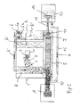
- FIGS. 1 and 2 now a generally designated 1 processing machine is shown, which has a machining tool 2 for machining a workpiece W.
- the machining tool 2 is known per se and will therefore not be described. It is cooled in a likewise known manner by means of a circulating in a coolant circuit K 'coolant K.
- the chips S lifted from the workpiece W by the machining tool 2 reach a chip conveyor 10, which in the case shown here is designed as a circulating link belt by being flushed through a machine bed flush to the chip conveyor 10.
- the larger chips S are transported away from the processing machine 1 by the chip conveyor 10 and arrive at a receiving container A.
- the smaller chips fall through the chip conveyor 10 and reach a machine bed 5 of the processing machine 1.
- the machine bed 5 also captures the coolant dripping from the processing tool 2 Purchase. To make this out of the tub-like To remove machine bed 5 and drive the coolant circuit is a coolant pump 6 with two coolant pump units 6a and 6b (see FIG. 2 ), which pumps off the coolant K from the machine bed 5. This coolant K is then returned to the machining tool 2.
- the processing machine 1 In the described embodiment of the processing machine 1 is - as best of FIG. 2 apparent - further provided that the processing machine 1 has a machine bed flushing, so that the coolant K is not only routed to the machining tool 2, but also flows through the machine bed 5 and thus rinses the chips S from the machine bed.
- the processing machine 1 has a suction pump 11, with which the swept by the chips S coolant K pumped out of the machine bed 5 and via a line 12 a separator 13, in which the chips S from the Coolant K are separated, is supplied.
- the separator 13 may, for. B. a sieve 14, which is acted upon by the mixed with the chips S coolant K, in which case the chips S are retained in the sieve 14 and the coolant K is cleaned so.
- This cleaned coolant K is again returned to the machine bed 5 via another line 15.
- a layering of the not covered by the chip conveyor 10 chips S in the machine bed 5 and concomitantly clogging of the chip conveyor 10 and / or the coolant pump 6 upstream separation unit 7 is counteracted.
- the time between two cleaning intervals is thereby significantly increased, which counteracts machine downtime.
- the return of the purified coolant K via the further line 15 in the machine bed 5 has the advantage that in this way the concentration of the chips S in the machine bed 5 located in the coolant K is reduced because this coolant-chips mixture diluted by supplying the purified coolant K. becomes.
- a processing machine 1 is formed by the measures described, in which not only the larger of the costs incurred in the machining process chips S are transported away from the chip conveyor 10 in an advantageous manner.
Landscapes
- Engineering & Computer Science (AREA)
- Mechanical Engineering (AREA)
- Chemical & Material Sciences (AREA)
- Chemical Kinetics & Catalysis (AREA)
- Auxiliary Devices For Machine Tools (AREA)
Claims (4)
- Machine d'usinage servant à usiner une pièce à usiner (W) avec un outil d'usinage par enlèvement de copeaux (2), sachant qu'un agent de refroidissement (K) traversant un circuit d'agent de refroidissement (K') entraîné par une pompe à agent de refroidissement (6) est reconduit au moins à l'outil d'usinage (2), laquelle machine d'usinage présente un convoyeur de copeaux (10) servant à évacuer une fraction des copeaux (S) se formant lors du processus d'usinage par enlèvement de copeaux de la pièce à usiner (W), un banc de machine (5) disposé sous le convoyeur de copeaux (10), dans lequel une fraction des copeaux (S) formés lors du processus d'usinage de la pièce à usiner (W) et non évacués par le convoyeur de copeaux (10) et l'agent de refroidissement peuvent être reçus, une pompe à agent de refroidissement (6, 6a, 6b) ainsi qu'une unité de séparation (7) installée en amont de ladite pompe dans le circuit d'agent de refroidissement (K'), au moyen de laquelle l'agent de refroidissement (K) se trouvant dans le banc de machine (5) peut être aspiré par l'unité de séparation (7), caractérisée en ce que la machine d'usinage (1) présente une pompe d'aspiration (11) servant à aspirer une partie de l'agent de refroidissement (K) se trouvant dans le banc de machine, traversés par des copeaux (S), ainsi qu'un système de séparation (13), auquel l'agent de refroidissement (K) aspiré par la pompe d'aspiration (11) peut être conduit en paissant par une conduite (12), en ce que la pompe d'aspiration (11) fonctionnant en parallèle de la pompe à agent de refroidissement (6) entraînant le circuit d'agent de refroidissement (K') ainsi que le système de séparation (13) sont disposés à l'extérieur du circuit d'agent de refroidissement (K'), et en ce que le système de séparation (13) sépare de l'agent de refroidissement (K) aspiré au moins une fraction des copeaux (S) s'y trouvant, et en ce que l'agent de refroidissement (K) ainsi épuré est amené par une autre conduite (15) au circuit d'agent de refroidissement.
- Machine d'usinage selon la revendication 1, caractérisée en ce que le dispositif de séparation (13) comporte un tamis (14) servant à séparer les copeaux (S) de l'agent de refroidissement (K).
- Machine d'usinage selon l'une quelconque des revendications précédentes, caractérisée en ce que l'autre conduite (15) débouche dans le banc de machine (5).
- Machine d'usinage selon la revendication 3, caractérisée en ce que l'autre conduite (15) débouche, dans le banc de machine, dans la zone de l'extrémité, opposée à la pompe d'aspiration (11), du banc de machine (5).
Applications Claiming Priority (2)
| Application Number | Priority Date | Filing Date | Title |
|---|---|---|---|
| DE201210008900 DE102012008900B3 (de) | 2012-05-08 | 2012-05-08 | Bearbeitungsmaschine |
| DE202012004436U DE202012004436U1 (de) | 2012-05-08 | 2012-05-08 | Bearbeitungsmaschine |
Publications (2)
| Publication Number | Publication Date |
|---|---|
| EP2662183A1 EP2662183A1 (fr) | 2013-11-13 |
| EP2662183B1 true EP2662183B1 (fr) | 2015-04-08 |
Family
ID=48430407
Family Applications (1)
| Application Number | Title | Priority Date | Filing Date |
|---|---|---|---|
| EP13002415.1A Not-in-force EP2662183B1 (fr) | 2012-05-08 | 2013-05-06 | Machine de traitement |
Country Status (1)
| Country | Link |
|---|---|
| EP (1) | EP2662183B1 (fr) |
Families Citing this family (4)
| Publication number | Priority date | Publication date | Assignee | Title |
|---|---|---|---|---|
| CN103921164B (zh) * | 2014-03-31 | 2016-09-14 | 温州市兴泰科技有限公司 | 钢管切割废液收集装置 |
| WO2018188703A1 (fr) * | 2017-04-11 | 2018-10-18 | Accustrip Aps | Procédé de filtration de liquide de refroidissement et système de filtration |
| CN108127163B (zh) * | 2017-12-21 | 2019-03-15 | 重庆千乔机电有限公司 | 建材切割装置 |
| CN110961736B (zh) * | 2020-01-04 | 2021-02-26 | 共和精英塑胶五金制品(深圳)有限公司 | 一种线切割机冷却液的铁屑清理装置 |
Family Cites Families (8)
| Publication number | Priority date | Publication date | Assignee | Title |
|---|---|---|---|---|
| DE3127440A1 (de) | 1981-07-11 | 1983-03-03 | MDS Mannesmann Demag Sack GmbH, 4000 Düsseldorf | Kuehlschmierstoff-trenn- und reinigungsvorrichtung |
| DE8717994U1 (de) | 1987-12-22 | 1992-03-26 | D + S Fördertechnik GmbH, 7860 Schopfheim | Reinigungsvorrichtung zum Abscheiden von Werkstückspänen |
| US6612314B2 (en) * | 2001-06-29 | 2003-09-02 | Jack R. Bratten | Process for removing oil containing machining fluid from machined chips |
| DE10144157C1 (de) | 2001-09-07 | 2003-02-20 | Interlit Joistgen Gmbh | Vorrichtung zum Separieren und Austragen von Spänen |
| US7410569B1 (en) * | 2005-11-18 | 2008-08-12 | Turhan A. Tilev | Filtration system for metalworking fluids |
| JP2008012603A (ja) | 2006-07-03 | 2008-01-24 | Toyota Motor Corp | クーラント浄化装置 |
| EP2168715A1 (fr) * | 2008-09-26 | 2010-03-31 | Tornos SA | Système de traitement d'huile d'usinage |
| DE202009009535U1 (de) | 2009-07-13 | 2009-09-17 | Deckel Maho Pfronten Gmbh | Vorrichtung zur Aufbereitung von Kühlschmierstoff |
-
2013
- 2013-05-06 EP EP13002415.1A patent/EP2662183B1/fr not_active Not-in-force
Also Published As
| Publication number | Publication date |
|---|---|
| EP2662183A1 (fr) | 2013-11-13 |
Similar Documents
| Publication | Publication Date | Title |
|---|---|---|
| EP2283908B1 (fr) | Dispositif destiné à la préparation de lubrifiant réfrigérant | |
| DE29519626U1 (de) | Reinigungsvorrichtung | |
| DE102004060950A1 (de) | Geschirrspülmaschine mit wartungsarmem Siebsystem | |
| EP2662183B1 (fr) | Machine de traitement | |
| DE60204500T2 (de) | Industrielle Filtrationsvorrichtung mit Anordung zur Abtrennung von Bearbeitungsspänen aus der Kühlflüssigkeit vor der Filtration | |
| DE10035725C2 (de) | Späneförderer | |
| DE102012008900B3 (de) | Bearbeitungsmaschine | |
| EP1476275B1 (fr) | Dispositif de reception et separation de copeaux et de liquide tombant de machines-outils (debordement) | |
| EP1257341A1 (fr) | Procede et dispositif pour epurer des liquides | |
| DE202016101410U1 (de) | Kühlschmierstoffeinrichtung für eine Werkzeugmaschine | |
| DE202006009150U1 (de) | Filtervorrichtung für Kühlschmierflüssigkeit | |
| EP1291059B1 (fr) | Dispositif de séparation et élimination des copeaux | |
| DE3743508C2 (de) | Reinigungsvorrichtung | |
| DE202012004436U1 (de) | Bearbeitungsmaschine | |
| EP2228114A1 (fr) | Installation de nettoyage | |
| DE102016104678B4 (de) | Kühlschmierstoffeinrichtung für eine Werkzeugmaschine | |
| WO2003064106A1 (fr) | Dispositif de separation et d'extraction de copeaux et de liquide de travail | |
| EP1375061B1 (fr) | Dispositif pour l'enlèvement de copeaux | |
| AT522690A4 (de) | Aufbereitungseinrichtung und Verfahren zum Aufbereiten von mit Feststoffen beladener Prozessflüssigkeit | |
| DE10219454C1 (de) | Vorrichtung zur Förderung von mit Spänen versetztem Kühlschmierstoff | |
| EP1270056B1 (fr) | Filtre à liquid, en particulier pour réfrigerants lubrifiants encrasés | |
| DE102012102203B4 (de) | Vorrichtung zur Reinigung eines Fluides | |
| WO2003031116A2 (fr) | Dispositif destine a l'evacuation de copeaux et de liquide de coupe | |
| DE3823486C1 (fr) | ||
| DE202023101746U1 (de) | Vorrichtung zum Abscheiden von Feststoffpartikeln aus einer Flüssigkeit |
Legal Events
| Date | Code | Title | Description |
|---|---|---|---|
| PUAI | Public reference made under article 153(3) epc to a published international application that has entered the european phase |
Free format text: ORIGINAL CODE: 0009012 |
|
| AK | Designated contracting states |
Kind code of ref document: A1 Designated state(s): AL AT BE BG CH CY CZ DE DK EE ES FI FR GB GR HR HU IE IS IT LI LT LU LV MC MK MT NL NO PL PT RO RS SE SI SK SM TR |
|
| AX | Request for extension of the european patent |
Extension state: BA ME |
|
| 17P | Request for examination filed |
Effective date: 20140506 |
|
| RBV | Designated contracting states (corrected) |
Designated state(s): AL AT BE BG CH CY CZ DE DK EE ES FI FR GB GR HR HU IE IS IT LI LT LU LV MC MK MT NL NO PL PT RO RS SE SI SK SM TR |
|
| 17Q | First examination report despatched |
Effective date: 20140627 |
|
| GRAP | Despatch of communication of intention to grant a patent |
Free format text: ORIGINAL CODE: EPIDOSNIGR1 |
|
| INTG | Intention to grant announced |
Effective date: 20141023 |
|
| GRAS | Grant fee paid |
Free format text: ORIGINAL CODE: EPIDOSNIGR3 |
|
| GRAA | (expected) grant |
Free format text: ORIGINAL CODE: 0009210 |
|
| AK | Designated contracting states |
Kind code of ref document: B1 Designated state(s): AL AT BE BG CH CY CZ DE DK EE ES FI FR GB GR HR HU IE IS IT LI LT LU LV MC MK MT NL NO PL PT RO RS SE SI SK SM TR |
|
| REG | Reference to a national code |
Ref country code: GB Ref legal event code: FG4D Free format text: NOT ENGLISH |
|
| REG | Reference to a national code |
Ref country code: CH Ref legal event code: EP |
|
| REG | Reference to a national code |
Ref country code: IE Ref legal event code: FG4D Free format text: LANGUAGE OF EP DOCUMENT: GERMAN |
|
| REG | Reference to a national code |
Ref country code: DE Ref legal event code: R096 Ref document number: 502013000519 Country of ref document: DE Effective date: 20150513 |
|
| REG | Reference to a national code |
Ref country code: AT Ref legal event code: REF Ref document number: 720155 Country of ref document: AT Kind code of ref document: T Effective date: 20150515 |
|
| REG | Reference to a national code |
Ref country code: NL Ref legal event code: VDEP Effective date: 20150408 |
|
| REG | Reference to a national code |
Ref country code: LT Ref legal event code: MG4D |
|
| PG25 | Lapsed in a contracting state [announced via postgrant information from national office to epo] |
Ref country code: NL Free format text: LAPSE BECAUSE OF FAILURE TO SUBMIT A TRANSLATION OF THE DESCRIPTION OR TO PAY THE FEE WITHIN THE PRESCRIBED TIME-LIMIT Effective date: 20150408 |
|
| PG25 | Lapsed in a contracting state [announced via postgrant information from national office to epo] |
Ref country code: ES Free format text: LAPSE BECAUSE OF FAILURE TO SUBMIT A TRANSLATION OF THE DESCRIPTION OR TO PAY THE FEE WITHIN THE PRESCRIBED TIME-LIMIT Effective date: 20150408 Ref country code: HR Free format text: LAPSE BECAUSE OF FAILURE TO SUBMIT A TRANSLATION OF THE DESCRIPTION OR TO PAY THE FEE WITHIN THE PRESCRIBED TIME-LIMIT Effective date: 20150408 Ref country code: PT Free format text: LAPSE BECAUSE OF FAILURE TO SUBMIT A TRANSLATION OF THE DESCRIPTION OR TO PAY THE FEE WITHIN THE PRESCRIBED TIME-LIMIT Effective date: 20150810 Ref country code: LT Free format text: LAPSE BECAUSE OF FAILURE TO SUBMIT A TRANSLATION OF THE DESCRIPTION OR TO PAY THE FEE WITHIN THE PRESCRIBED TIME-LIMIT Effective date: 20150408 Ref country code: FI Free format text: LAPSE BECAUSE OF FAILURE TO SUBMIT A TRANSLATION OF THE DESCRIPTION OR TO PAY THE FEE WITHIN THE PRESCRIBED TIME-LIMIT Effective date: 20150408 Ref country code: NO Free format text: LAPSE BECAUSE OF FAILURE TO SUBMIT A TRANSLATION OF THE DESCRIPTION OR TO PAY THE FEE WITHIN THE PRESCRIBED TIME-LIMIT Effective date: 20150708 |
|
| PG25 | Lapsed in a contracting state [announced via postgrant information from national office to epo] |
Ref country code: RS Free format text: LAPSE BECAUSE OF FAILURE TO SUBMIT A TRANSLATION OF THE DESCRIPTION OR TO PAY THE FEE WITHIN THE PRESCRIBED TIME-LIMIT Effective date: 20150408 Ref country code: LV Free format text: LAPSE BECAUSE OF FAILURE TO SUBMIT A TRANSLATION OF THE DESCRIPTION OR TO PAY THE FEE WITHIN THE PRESCRIBED TIME-LIMIT Effective date: 20150408 Ref country code: GR Free format text: LAPSE BECAUSE OF FAILURE TO SUBMIT A TRANSLATION OF THE DESCRIPTION OR TO PAY THE FEE WITHIN THE PRESCRIBED TIME-LIMIT Effective date: 20150709 Ref country code: IS Free format text: LAPSE BECAUSE OF FAILURE TO SUBMIT A TRANSLATION OF THE DESCRIPTION OR TO PAY THE FEE WITHIN THE PRESCRIBED TIME-LIMIT Effective date: 20150808 |
|
| REG | Reference to a national code |
Ref country code: DE Ref legal event code: R097 Ref document number: 502013000519 Country of ref document: DE |
|
| PG25 | Lapsed in a contracting state [announced via postgrant information from national office to epo] |
Ref country code: DK Free format text: LAPSE BECAUSE OF FAILURE TO SUBMIT A TRANSLATION OF THE DESCRIPTION OR TO PAY THE FEE WITHIN THE PRESCRIBED TIME-LIMIT Effective date: 20150408 Ref country code: MC Free format text: LAPSE BECAUSE OF FAILURE TO SUBMIT A TRANSLATION OF THE DESCRIPTION OR TO PAY THE FEE WITHIN THE PRESCRIBED TIME-LIMIT Effective date: 20150408 Ref country code: IT Free format text: LAPSE BECAUSE OF FAILURE TO SUBMIT A TRANSLATION OF THE DESCRIPTION OR TO PAY THE FEE WITHIN THE PRESCRIBED TIME-LIMIT Effective date: 20150408 Ref country code: EE Free format text: LAPSE BECAUSE OF FAILURE TO SUBMIT A TRANSLATION OF THE DESCRIPTION OR TO PAY THE FEE WITHIN THE PRESCRIBED TIME-LIMIT Effective date: 20150408 |
|
| PLBE | No opposition filed within time limit |
Free format text: ORIGINAL CODE: 0009261 |
|
| STAA | Information on the status of an ep patent application or granted ep patent |
Free format text: STATUS: NO OPPOSITION FILED WITHIN TIME LIMIT |
|
| REG | Reference to a national code |
Ref country code: IE Ref legal event code: MM4A |
|
| REG | Reference to a national code |
Ref country code: FR Ref legal event code: ST Effective date: 20160129 |
|
| PG25 | Lapsed in a contracting state [announced via postgrant information from national office to epo] |
Ref country code: RO Free format text: LAPSE BECAUSE OF NON-PAYMENT OF DUE FEES Effective date: 20150408 Ref country code: SK Free format text: LAPSE BECAUSE OF FAILURE TO SUBMIT A TRANSLATION OF THE DESCRIPTION OR TO PAY THE FEE WITHIN THE PRESCRIBED TIME-LIMIT Effective date: 20150408 Ref country code: PL Free format text: LAPSE BECAUSE OF FAILURE TO SUBMIT A TRANSLATION OF THE DESCRIPTION OR TO PAY THE FEE WITHIN THE PRESCRIBED TIME-LIMIT Effective date: 20150408 Ref country code: CZ Free format text: LAPSE BECAUSE OF FAILURE TO SUBMIT A TRANSLATION OF THE DESCRIPTION OR TO PAY THE FEE WITHIN THE PRESCRIBED TIME-LIMIT Effective date: 20150408 |
|
| 26N | No opposition filed |
Effective date: 20160111 |
|
| PG25 | Lapsed in a contracting state [announced via postgrant information from national office to epo] |
Ref country code: IE Free format text: LAPSE BECAUSE OF NON-PAYMENT OF DUE FEES Effective date: 20150506 |
|
| PG25 | Lapsed in a contracting state [announced via postgrant information from national office to epo] |
Ref country code: FR Free format text: LAPSE BECAUSE OF NON-PAYMENT OF DUE FEES Effective date: 20150608 Ref country code: SI Free format text: LAPSE BECAUSE OF FAILURE TO SUBMIT A TRANSLATION OF THE DESCRIPTION OR TO PAY THE FEE WITHIN THE PRESCRIBED TIME-LIMIT Effective date: 20150408 |
|
| PGFP | Annual fee paid to national office [announced via postgrant information from national office to epo] |
Ref country code: DE Payment date: 20160418 Year of fee payment: 4 |
|
| PG25 | Lapsed in a contracting state [announced via postgrant information from national office to epo] |
Ref country code: MT Free format text: LAPSE BECAUSE OF FAILURE TO SUBMIT A TRANSLATION OF THE DESCRIPTION OR TO PAY THE FEE WITHIN THE PRESCRIBED TIME-LIMIT Effective date: 20150408 |
|
| REG | Reference to a national code |
Ref country code: CH Ref legal event code: PL |
|
| PG25 | Lapsed in a contracting state [announced via postgrant information from national office to epo] |
Ref country code: CH Free format text: LAPSE BECAUSE OF NON-PAYMENT OF DUE FEES Effective date: 20160531 Ref country code: LI Free format text: LAPSE BECAUSE OF NON-PAYMENT OF DUE FEES Effective date: 20160531 |
|
| PG25 | Lapsed in a contracting state [announced via postgrant information from national office to epo] |
Ref country code: BG Free format text: LAPSE BECAUSE OF FAILURE TO SUBMIT A TRANSLATION OF THE DESCRIPTION OR TO PAY THE FEE WITHIN THE PRESCRIBED TIME-LIMIT Effective date: 20150408 Ref country code: HU Free format text: LAPSE BECAUSE OF FAILURE TO SUBMIT A TRANSLATION OF THE DESCRIPTION OR TO PAY THE FEE WITHIN THE PRESCRIBED TIME-LIMIT; INVALID AB INITIO Effective date: 20130506 |
|
| PG25 | Lapsed in a contracting state [announced via postgrant information from national office to epo] |
Ref country code: CY Free format text: LAPSE BECAUSE OF FAILURE TO SUBMIT A TRANSLATION OF THE DESCRIPTION OR TO PAY THE FEE WITHIN THE PRESCRIBED TIME-LIMIT Effective date: 20150408 Ref country code: SE Free format text: LAPSE BECAUSE OF FAILURE TO SUBMIT A TRANSLATION OF THE DESCRIPTION OR TO PAY THE FEE WITHIN THE PRESCRIBED TIME-LIMIT Effective date: 20150408 |
|
| PG25 | Lapsed in a contracting state [announced via postgrant information from national office to epo] |
Ref country code: BE Free format text: LAPSE BECAUSE OF NON-PAYMENT OF DUE FEES Effective date: 20150531 |
|
| PG25 | Lapsed in a contracting state [announced via postgrant information from national office to epo] |
Ref country code: TR Free format text: LAPSE BECAUSE OF FAILURE TO SUBMIT A TRANSLATION OF THE DESCRIPTION OR TO PAY THE FEE WITHIN THE PRESCRIBED TIME-LIMIT Effective date: 20150408 |
|
| PG25 | Lapsed in a contracting state [announced via postgrant information from national office to epo] |
Ref country code: LU Free format text: LAPSE BECAUSE OF NON-PAYMENT OF DUE FEES Effective date: 20150506 |
|
| REG | Reference to a national code |
Ref country code: DE Ref legal event code: R119 Ref document number: 502013000519 Country of ref document: DE |
|
| GBPC | Gb: european patent ceased through non-payment of renewal fee |
Effective date: 20170506 |
|
| PG25 | Lapsed in a contracting state [announced via postgrant information from national office to epo] |
Ref country code: DE Free format text: LAPSE BECAUSE OF NON-PAYMENT OF DUE FEES Effective date: 20171201 Ref country code: GB Free format text: LAPSE BECAUSE OF NON-PAYMENT OF DUE FEES Effective date: 20170506 |
|
| PG25 | Lapsed in a contracting state [announced via postgrant information from national office to epo] |
Ref country code: SM Free format text: LAPSE BECAUSE OF FAILURE TO SUBMIT A TRANSLATION OF THE DESCRIPTION OR TO PAY THE FEE WITHIN THE PRESCRIBED TIME-LIMIT Effective date: 20150408 |
|
| PG25 | Lapsed in a contracting state [announced via postgrant information from national office to epo] |
Ref country code: MK Free format text: LAPSE BECAUSE OF FAILURE TO SUBMIT A TRANSLATION OF THE DESCRIPTION OR TO PAY THE FEE WITHIN THE PRESCRIBED TIME-LIMIT Effective date: 20150408 |
|
| PG25 | Lapsed in a contracting state [announced via postgrant information from national office to epo] |
Ref country code: AL Free format text: LAPSE BECAUSE OF FAILURE TO SUBMIT A TRANSLATION OF THE DESCRIPTION OR TO PAY THE FEE WITHIN THE PRESCRIBED TIME-LIMIT Effective date: 20150408 |
|
| REG | Reference to a national code |
Ref country code: AT Ref legal event code: MM01 Ref document number: 720155 Country of ref document: AT Kind code of ref document: T Effective date: 20180506 |
|
| PG25 | Lapsed in a contracting state [announced via postgrant information from national office to epo] |
Ref country code: AT Free format text: LAPSE BECAUSE OF NON-PAYMENT OF DUE FEES Effective date: 20180506 |