EP2662175A2 - Two-stage interlocked sliding door for machining tank of electric discharge machine - Google Patents
Two-stage interlocked sliding door for machining tank of electric discharge machine Download PDFInfo
- Publication number
- EP2662175A2 EP2662175A2 EP13163457.8A EP13163457A EP2662175A2 EP 2662175 A2 EP2662175 A2 EP 2662175A2 EP 13163457 A EP13163457 A EP 13163457A EP 2662175 A2 EP2662175 A2 EP 2662175A2
- Authority
- EP
- European Patent Office
- Prior art keywords
- door
- lifting
- machining tank
- belt
- pulleys
- Prior art date
- Legal status (The legal status is an assumption and is not a legal conclusion. Google has not performed a legal analysis and makes no representation as to the accuracy of the status listed.)
- Granted
Links
- 238000003754 machining Methods 0.000 title claims abstract description 47
- 239000012530 fluid Substances 0.000 description 3
- 238000010420 art technique Methods 0.000 description 2
- 238000000034 method Methods 0.000 description 2
- 230000007257 malfunction Effects 0.000 description 1
- 230000001105 regulatory effect Effects 0.000 description 1
Images




Classifications
-
- E—FIXED CONSTRUCTIONS
- E05—LOCKS; KEYS; WINDOW OR DOOR FITTINGS; SAFES
- E05D—HINGES OR SUSPENSION DEVICES FOR DOORS, WINDOWS OR WINGS
- E05D13/00—Accessories for sliding or lifting wings, e.g. pulleys, safety catches
-
- B—PERFORMING OPERATIONS; TRANSPORTING
- B23—MACHINE TOOLS; METAL-WORKING NOT OTHERWISE PROVIDED FOR
- B23H—WORKING OF METAL BY THE ACTION OF A HIGH CONCENTRATION OF ELECTRIC CURRENT ON A WORKPIECE USING AN ELECTRODE WHICH TAKES THE PLACE OF A TOOL; SUCH WORKING COMBINED WITH OTHER FORMS OF WORKING OF METAL
- B23H11/00—Auxiliary apparatus or details, not otherwise provided for
-
- E—FIXED CONSTRUCTIONS
- E05—LOCKS; KEYS; WINDOW OR DOOR FITTINGS; SAFES
- E05D—HINGES OR SUSPENSION DEVICES FOR DOORS, WINDOWS OR WINGS
- E05D15/00—Suspension arrangements for wings
- E05D15/48—Suspension arrangements for wings allowing alternative movements
-
- B—PERFORMING OPERATIONS; TRANSPORTING
- B23—MACHINE TOOLS; METAL-WORKING NOT OTHERWISE PROVIDED FOR
- B23H—WORKING OF METAL BY THE ACTION OF A HIGH CONCENTRATION OF ELECTRIC CURRENT ON A WORKPIECE USING AN ELECTRODE WHICH TAKES THE PLACE OF A TOOL; SUCH WORKING COMBINED WITH OTHER FORMS OF WORKING OF METAL
- B23H1/00—Electrical discharge machining, i.e. removing metal with a series of rapidly recurring electrical discharges between an electrode and a workpiece in the presence of a fluid dielectric
- B23H1/10—Supply or regeneration of working media
-
- B—PERFORMING OPERATIONS; TRANSPORTING
- B23—MACHINE TOOLS; METAL-WORKING NOT OTHERWISE PROVIDED FOR
- B23H—WORKING OF METAL BY THE ACTION OF A HIGH CONCENTRATION OF ELECTRIC CURRENT ON A WORKPIECE USING AN ELECTRODE WHICH TAKES THE PLACE OF A TOOL; SUCH WORKING COMBINED WITH OTHER FORMS OF WORKING OF METAL
- B23H7/00—Processes or apparatus applicable to both electrical discharge machining and electrochemical machining
- B23H7/36—Supply or regeneration of working media
Definitions
- the present invention relates to a two-stage sliding door for a machining tank of an electric discharge machine.
- a workpiece is fixed in a machining tank containing machining fluid and undergoes electric discharge machining in a state where the workpiece is immersed in the machining fluid.
- the machining tank has a lifting door on its front that moves up and down with respect to a door frame for facilitating removal of a processed workpiece from the machining tank and setting of a workpiece into the machining tank from outside.
- a simplest conventional structure of such a machining tank is described below with reference to Figs. 9 to 11 .
- a door 11 attached to the front of the machining tank includes a door base member 1 serving as a door frame, first and second lifting doors 2 and 3 that move up and down with respect to the door base member 1, a door cover 4 serving as a fixing cover, and a driving mechanism (not shown) for lifting and lowering the second lifting door 3.
- the first lifting door 2 is formed of two planar members of different heights disposed in front of each other at a certain spacing.
- the taller planar member has an opening formed in a center thereof, and the upper ends of the left and right portions except the center are folded forward so as to form stoppers 10.
- the shorter planar member has a height up to the opening in the taller planar member.
- the second lifting door 3 is formed of a single planar member having the same height as the shorter planar member of the first lifting door 2, and is fitted between the two planar members forming the first lifting door 2.
- the door base member 1 has an opening 20 formed in the center thereof. The opening 20 is not closed by the first and second lifting doors 2 and 3 when the first and second lifting doors 2 and 3 are at the lowered position, in which the second lifting door 3 is fitted between the two planar members forming the first lifting door 2, as illustrated in Fig. 9 .
- the second lifting door 3 When the second lifting door 3 is lifted by the driving device from the position shown in Fig. 9 , the second lifting door 3 gets out from between the two planar members forming the first lifting door 2 and the upper end of the second lifting door 3 abuts against the stoppers 10 of the first lifting door 2.
- the first lifting door 2 When the second lifting door 3 is further lifted, the first lifting door 2 also moves up with the second lifting door 3 and the opening 20 on the front of the door base member 1 is closed by the first and second lifting doors 2 and 3 as shown in Fig. 11 .
- the machining fluid in the machining tank is maintained at a high level.
- the driving device needs to drive the first and second lifting doors 2 and 3 with the same stroke. Additionally, because load on the driving device varies when the second lifting door 3 comes into contact with the stoppers 10 of the first lifting door 2, control to keep the lifting speed of the second lifting door 3 constant is difficult. Furthermore, there is a risk of a hand of an operator present near the machining tank door 11 getting caught when the lifting second lifting door 3 comes into contact with the stoppers 10 of the first lifting door 2.
- Japanese Patent Application Laid-Open No. 6-55349 discloses a machining tank of a wire electric discharge machine that includes a base container member, first and second movable container members, and an elevator for sliding the first and second movable container members in cooperation with each other up and down with respect to the base container member.
- a machining tank With this machining tank, side walls of the base container member are partially open to a point lower than the top surface of a table on which a workpiece is secured.
- the elevator is driven to slide the first and second movable container members in cooperation with each other upward with respect to the base container member, the opening portion in the side walls of the base container member is closed, forming a machining tank surrounded by high side walls on all of the four sides.
- the first and second movable container members When the elevator is driven to slide the first and second movable container members in cooperation with each other downward with respect to the base container member, the first and second movable container members are fitted into the base container member such that the first and second movable container members are nested.
- the side walls of the machining tank descend to a position lower than the top surface of the table on which a workpiece is fixed, so workpiece replacement can be easily done over the lowered side walls, i.e., removing the workpiece from the table outside the machining tank or setting a workpiece on the table.
- the present invention addresses the above problems of the prior art technique with the object of providing a two-stage interlocked sliding door having a lifting mechanism with pulleys and a belt, for a machining tank of an electric discharge machine.
- the two-stage sliding door for a machining tank of an electric discharge machine includes a door frame, a first door that is fitted in the door frame and moves over a predetermined stroke, and a second door that moves over a stroke longer than the stroke of the first door, the second door is fitted inside the first door, and the first door is fitted between a fixing cover and the door frame.
- the sliding door further includes: two pulleys, one of which being disposed at an upper part of a side surface of the first door and the other one being disposed at a lower part of the side surface of the first door; an endless belt wound around the two pulleys; and first and second fixing members respectively attached to the door frame and the second door and fixing the belt.
- a part of the belt on one side of the straight line connecting the centers of rotation of the two pulleys is fixed to the first fixing member attached to the door frame, and a part of the belt on the other side is fixed to the second fixing member attached to the second door.
- the two pulleys may be disposed either on only one of left and right side surfaces of the first door or on both of the left and right side surfaces.
- the entire portion of the two-stage interlocked sliding door may be made openable and closable with respect to the machining tank by fixing one edge of the door frame to a hinge and fixing one side of the hinge to the machining tank.
- the ends of a shaft rotatably supporting each of the pulleys may be respectively affixed to left and right vertical boards attached to an edge of the second door.
- a two-stage interlocked sliding door having a lifting mechanism with pulleys and a belt, for a machining tank of an electric discharge machine.
- the door 11 for attachment on the front of the machining tank 12 shown in Fig. 1 includes a door base member 1 serving as a door frame, first and second lifting doors 2 and 3 that move up and down with respect to the door base member 1, a door cover 4 serving as a fixing cover, and a driving mechanism (not shown) for lifting and lowering the second lifting door 3.
- the first lifting door 2 is formed of two planar members of different heights disposed back and forth at a certain spacing.
- the taller planar member has an opening formed in a center thereof, while the shorter planar member has a height up to the opening in the taller planar member.
- the second lifting door 3, which is formed of a single planar member, is fitted between the two planar members forming the first lifting door 2.
- the height of the planar member forming the second lifting door 3 is substantially the same as the height of the shorter planar member forming the first lifting door 2.
- the door base member 1 has an opening 20 formed in the center thereof.
- the opening 20 is not closed by the first and second lifting doors 2 and 3 when the first and second lifting doors 2 and 3 are at the lowered position, as shown in Fig. 2 .
- Pulleys 5, 5 are attached at upper and lower parts of one end surface of the taller planar member forming the first lifting door 2.
- an endless belt 7 is wound around the pulleys 5, 5.
- a first belt-attaching member 6 is fixed at a part of the belt 7 on one side of the straight line connecting the centers of rotation of the upper and lower pulleys 5, 5, and a second belt-attaching member 8 is fixed at a part of the belt 7 on the other side.
- the first belt-attaching member 6 is fixed to the door base member 1 and the second belt-attaching member 8 is fixed to the second lifting door 3.
- the tension of the belt 7 is controlled by increasing the distance between the upper and lower pulleys 5, 5 with a belt tension adjustment member 9.
- the pulleys 5, 5 attached to the first lifting door 2 When the first lifting door 2 is lifted through driving of a driving device (not shown), the pulleys 5, 5 attached to the first lifting door 2 also move up as shown in Fig. 3 , and in turn the endless belt 7 wound around the pulleys 5, 5 and fixed to the door base member 1 via the first belt-attaching member 6 rotate. Consequently, the second lifting door 3 fixed to the belt 7 via the second belt-attaching member 8 moves up with respect to the first lifting door 2, on which the pulleys 5, 5 are attached (that is, the second lifting door 3 gradually gets out upward from between the two planar members forming the first lifting door 2). Thus, while the movement of the second lifting door 3 takes place in cooperation with the movement of the first lifting door 2, the travel (stroke) of the second lifting door 3 is half the travel (stroke) of the first lifting door 2.
- Fig. 4 shows that the first lifting door 2 has reached the uppermost position through driving of the driving device. In this position, most part of the second lifting door 3 has gotten out upward from between the two planar members forming the first lifting door 2, and the second lifting door 3 and the first lifting door 2 close the opening 20 formed in the door base member 1.
- the two-stage interlocked sliding door for a machining tank can achieve the closed state of the door 11 illustrated in Fig. 4 by lifting the first lifting door 2 with a stroke half that of the second lifting door 3. Also, since the force (load) necessary for lifting the first lifting door 2 (and the second lifting door 3 in cooperation with each other) with the driving device is invariant regardless of the position of the first lifting door 2 (and the second lifting door 3), the speed of lifting and lowering the first lifting door 2 (and the second lifting door 3) with the driving device can be easily controlled at a constant speed. Moreover, since it is not necessary to form the stopper 10 on the first lifting door 2 for regulating the elevation of the second lifting door 3 as in the prior art technique (see Fig. 9 ), there is no risk of a hand or the like of the operator getting caught between the second lifting door 3 and the stopper 10.
- pulleys 5, 5 are attached at upper and lower parts of the right end surface of the first lifting door 2 in the example shown in Figs. 2 to 4 , the pulleys 5, 5 may be attached at upper and lower parts of both of the left and right end surfaces of the first lifting door 2.
- Fig. 5 is a front view showing a state in which the first and second lifting doors 2 and 3 are moving up/down, indicating that the weight of the second lifting door 3 is applied to the belt 7 via the second belt-attaching member 8 and consequently moments shown at reference numeral 15 in Fig. 5 associated with the load of the belt 7 act on the pulleys 5.
- the moments 15 acting on the pulleys 5 can cause deformation or distortion in shafts rotatably supporting the pulleys 5 and/or their bearings (not shown), possibly resulting in deflection of the belt 7 and/or malfunction of the first and second lifting doors 2 and 3.
- a pulley holding member 14 having a shape of an elongate bottomless box such as shown in Figs. 6 and 7 is attached to the first lifting door 2, and the pulleys 5, 5 are affixed to the pulley holding member 14.
- the pulley holding member 14 is shaped in an elongate bottomless box formed of left and right two long vertical boards, and upper and lower short horizontal boards respectively connecting the upper and bottom edges of the vertical boards.
- the shafts of the pulleys 5 are attached between the left and right vertical boards.
- the shafts of the pulleys 5 are supported at both of their left and right ends by the left and right side boards that form the pulley holding member 14, not in a cantilevered manner as shown in Fig. 5 .
- machining tank door 11 and the machining tank 12 By connecting the machining tank door 11 and the machining tank 12 with a hinge 13 as illustrated in Fig. 8 , the entire portion of the machining tank door 11 can be opened, improving the accessibility of the machining tank to the operator.
Landscapes
- Engineering & Computer Science (AREA)
- Mechanical Engineering (AREA)
- Electrical Discharge Machining, Electrochemical Machining, And Combined Machining (AREA)
- Chemical & Material Sciences (AREA)
- Chemical Kinetics & Catalysis (AREA)
- Electrochemistry (AREA)
Abstract
Description
- The present invention relates to a two-stage sliding door for a machining tank of an electric discharge machine.
- In a typical electric discharge machine, a workpiece is fixed in a machining tank containing machining fluid and undergoes electric discharge machining in a state where the workpiece is immersed in the machining fluid. The machining tank has a lifting door on its front that moves up and down with respect to a door frame for facilitating removal of a processed workpiece from the machining tank and setting of a workpiece into the machining tank from outside. A simplest conventional structure of such a machining tank is described below with reference to
Figs. 9 to 11 . - As illustrated in
Fig. 9 , adoor 11 attached to the front of the machining tank includes adoor base member 1 serving as a door frame, first andsecond lifting doors door base member 1, adoor cover 4 serving as a fixing cover, and a driving mechanism (not shown) for lifting and lowering thesecond lifting door 3. Thefirst lifting door 2 is formed of two planar members of different heights disposed in front of each other at a certain spacing. The taller planar member has an opening formed in a center thereof, and the upper ends of the left and right portions except the center are folded forward so as to formstoppers 10. The shorter planar member has a height up to the opening in the taller planar member. Thesecond lifting door 3 is formed of a single planar member having the same height as the shorter planar member of thefirst lifting door 2, and is fitted between the two planar members forming thefirst lifting door 2. Thedoor base member 1 has an opening 20 formed in the center thereof. The opening 20 is not closed by the first andsecond lifting doors second lifting doors second lifting door 3 is fitted between the two planar members forming thefirst lifting door 2, as illustrated inFig. 9 . - When the
second lifting door 3 is lifted by the driving device from the position shown inFig. 9 , thesecond lifting door 3 gets out from between the two planar members forming thefirst lifting door 2 and the upper end of the second liftingdoor 3 abuts against thestoppers 10 of thefirst lifting door 2. When thesecond lifting door 3 is further lifted, thefirst lifting door 2 also moves up with thesecond lifting door 3 and the opening 20 on the front of thedoor base member 1 is closed by the first andsecond lifting doors Fig. 11 . Thus, the machining fluid in the machining tank is maintained at a high level. - With this structure, however, in order to close the opening 20 in the
door base member 1 with the first andsecond lifting doors second lifting doors second lifting door 3 comes into contact with thestoppers 10 of thefirst lifting door 2, control to keep the lifting speed of thesecond lifting door 3 constant is difficult. Furthermore, there is a risk of a hand of an operator present near themachining tank door 11 getting caught when the liftingsecond lifting door 3 comes into contact with thestoppers 10 of thefirst lifting door 2. - Japanese Patent Application Laid-Open No.
6-55349 - The present invention addresses the above problems of the prior art technique with the object of providing a two-stage interlocked sliding door having a lifting mechanism with pulleys and a belt, for a machining tank of an electric discharge machine.
- The two-stage sliding door for a machining tank of an electric discharge machine according to the present invention includes a door frame, a first door that is fitted in the door frame and moves over a predetermined stroke, and a second door that moves over a stroke longer than the stroke of the first door, the second door is fitted inside the first door, and the first door is fitted between a fixing cover and the door frame. The sliding door further includes: two pulleys, one of which being disposed at an upper part of a side surface of the first door and the other one being disposed at a lower part of the side surface of the first door; an endless belt wound around the two pulleys; and first and second fixing members respectively attached to the door frame and the second door and fixing the belt. A part of the belt on one side of the straight line connecting the centers of rotation of the two pulleys is fixed to the first fixing member attached to the door frame, and a part of the belt on the other side is fixed to the second fixing member attached to the second door.
- The two pulleys may be disposed either on only one of left and right side surfaces of the first door or on both of the left and right side surfaces.
- The entire portion of the two-stage interlocked sliding door may be made openable and closable with respect to the machining tank by fixing one edge of the door frame to a hinge and fixing one side of the hinge to the machining tank.
- The ends of a shaft rotatably supporting each of the pulleys may be respectively affixed to left and right vertical boards attached to an edge of the second door.
- According to the present invention, it is possible to provide a two-stage interlocked sliding door having a lifting mechanism with pulleys and a belt, for a machining tank of an electric discharge machine.
- The forgoing and other objects and feature of the invention will be apparent from the following description of preferred embodiments of the invention with reference to the accompanying drawings, in which:
-
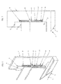
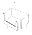
Fig. 1 is a perspective view of a machining tank of an electric discharge machine having a two-stage interlocked sliding door; -
Fig. 2 is a partial perspective view showing the two-stage sliding door for a machining tank of an electric discharge machine according to a first embodiment of the present invention; -
Fig. 3 is a partial perspective view showing the first and second lifting doors ofFig. 2 which are in the process of moving up/down in cooperation with each other; -
Fig. 4 is a partial perspective view showing a state in which the first and second lifting doors ofFig. 2 have been completely lifted and an opening formed in a door base member is closed by the first and second lifting doors; -
Fig. 5 is a partial front view of the sliding door as viewed from its front with the first and second lifting doors in the position ofFig. 3 ; -
Fig. 6 is a partial perspective view showing the two-stage sliding door for a machining tank of an electric discharge machine according to a second embodiment of the present invention; -
Fig. 7 is a partial front view of the sliding door shown inFig. 6 as viewed from its front; -
Fig. 8 is a perspective view showing the two-stage sliding door for a machining tank of an electric discharge machine according to a third embodiment of the present invention; -
Fig. 9 shows the structure of a conventional sliding door forming the machining tank of an electric discharge machine; -
Fig. 10 shows the sliding door shown inFig. 9 which is in the process of moving up; and -
Fig. 11 shows a state in which the sliding door shown inFig. 9 has been completely lifted and the opening formed on the front of the machining tank is closed by the sliding door. -
-
Fig. 1 is a perspective view of a machining tank of an electric discharge machine having a two-stage interlocked sliding door. Amachining tank door 11 is attached to the front of amachining tank 12. -
Fig. 2 illustrates the two-stage sliding door for a machining tank of an electric discharge machine according to a first embodiment of the present invention. - As shown in
Fig. 2 , thedoor 11 for attachment on the front of themachining tank 12 shown inFig. 1 includes adoor base member 1 serving as a door frame, first andsecond lifting doors door base member 1, adoor cover 4 serving as a fixing cover, and a driving mechanism (not shown) for lifting and lowering thesecond lifting door 3. - The
first lifting door 2 is formed of two planar members of different heights disposed back and forth at a certain spacing. The taller planar member has an opening formed in a center thereof, while the shorter planar member has a height up to the opening in the taller planar member. Thesecond lifting door 3, which is formed of a single planar member, is fitted between the two planar members forming thefirst lifting door 2. The height of the planar member forming the second liftingdoor 3 is substantially the same as the height of the shorter planar member forming thefirst lifting door 2. - The
door base member 1 has an opening 20 formed in the center thereof. The opening 20 is not closed by the first andsecond lifting doors second lifting doors Fig. 2 . -
Pulleys first lifting door 2. Around thepulleys endless belt 7 is wound. A first belt-attachingmember 6 is fixed at a part of thebelt 7 on one side of the straight line connecting the centers of rotation of the upper andlower pulleys member 8 is fixed at a part of thebelt 7 on the other side. The first belt-attachingmember 6 is fixed to thedoor base member 1 and the second belt-attachingmember 8 is fixed to thesecond lifting door 3. The tension of thebelt 7 is controlled by increasing the distance between the upper andlower pulleys tension adjustment member 9. - When the
first lifting door 2 is lifted through driving of a driving device (not shown), thepulleys first lifting door 2 also move up as shown inFig. 3 , and in turn theendless belt 7 wound around thepulleys door base member 1 via the first belt-attachingmember 6 rotate. Consequently, thesecond lifting door 3 fixed to thebelt 7 via the second belt-attachingmember 8 moves up with respect to thefirst lifting door 2, on which thepulleys second lifting door 3 gradually gets out upward from between the two planar members forming the first lifting door 2). Thus, while the movement of thesecond lifting door 3 takes place in cooperation with the movement of thefirst lifting door 2, the travel (stroke) of thesecond lifting door 3 is half the travel (stroke) of thefirst lifting door 2. -
Fig. 4 shows that thefirst lifting door 2 has reached the uppermost position through driving of the driving device. In this position, most part of thesecond lifting door 3 has gotten out upward from between the two planar members forming thefirst lifting door 2, and thesecond lifting door 3 and thefirst lifting door 2 close theopening 20 formed in thedoor base member 1. - As described above, the two-stage interlocked sliding door for a machining tank according to the present invention can achieve the closed state of the
door 11 illustrated inFig. 4 by lifting thefirst lifting door 2 with a stroke half that of thesecond lifting door 3. Also, since the force (load) necessary for lifting the first lifting door 2 (and thesecond lifting door 3 in cooperation with each other) with the driving device is invariant regardless of the position of the first lifting door 2 (and the second lifting door 3), the speed of lifting and lowering the first lifting door 2 (and the second lifting door 3) with the driving device can be easily controlled at a constant speed. Moreover, since it is not necessary to form thestopper 10 on thefirst lifting door 2 for regulating the elevation of thesecond lifting door 3 as in the prior art technique (seeFig. 9 ), there is no risk of a hand or the like of the operator getting caught between thesecond lifting door 3 and thestopper 10. - Although the
pulleys first lifting door 2 in the example shown inFigs. 2 to 4 , thepulleys first lifting door 2. -
Fig. 5 is a front view showing a state in which the first andsecond lifting doors second lifting door 3 is applied to thebelt 7 via the second belt-attachingmember 8 and consequently moments shown atreference numeral 15 inFig. 5 associated with the load of thebelt 7 act on thepulleys 5. Themoments 15 acting on thepulleys 5 can cause deformation or distortion in shafts rotatably supporting thepulleys 5 and/or their bearings (not shown), possibly resulting in deflection of thebelt 7 and/or malfunction of the first andsecond lifting doors - In order to solve this problem, a
pulley holding member 14 having a shape of an elongate bottomless box such as shown inFigs. 6 and 7 is attached to thefirst lifting door 2, and thepulleys pulley holding member 14. Thepulley holding member 14 is shaped in an elongate bottomless box formed of left and right two long vertical boards, and upper and lower short horizontal boards respectively connecting the upper and bottom edges of the vertical boards. The shafts of thepulleys 5 are attached between the left and right vertical boards. With this structure, the shafts of thepulleys 5 are supported at both of their left and right ends by the left and right side boards that form thepulley holding member 14, not in a cantilevered manner as shown inFig. 5 . This eliminates deformation or distortion in the shafts supporting thepulleys second lifting door 3 applied to thebelt 7 via the second belt-attachingmember 8. - By connecting the
machining tank door 11 and themachining tank 12 with ahinge 13 as illustrated inFig. 8 , the entire portion of themachining tank door 11 can be opened, improving the accessibility of the machining tank to the operator.
Claims (4)
- A two-stage interlocked sliding door for a machining tank of an electric discharge machine, which comprises a door frame, a first door that is fitted in the door frame and moves over a predetermined stroke, and a second door that moves over a stroke longer than the stroke of the first door, the second door being fitted inside the first door, and the first door being fitted between a fixing cover and the door frame, the two-stage interlocked sliding door further comprises:a first pulley of which is disposed at an upper part of a side surface of the first door and a second pulley which is disposed at a lower part of the side surface of the first door;an endless belt wound around the first and second pulleys; andfirst and second fixing members attached to the door frame and the second door, respectively, and fixing the belt; whereina part of the belt on one side of a straight line connecting centers of rotation of the first and second pulleys is fixed to the first fixing member attached to the door frame, and a part of the belt on another side is fixed to the second fixing member attached to the second door.
- The two-stage interlocked sliding door for a machining tank of an electric discharge machine according to claim 1, wherein the first and second pulleys are disposed either on only one of left and right side surfaces of the first door or on both of the left and right side surfaces.
- The two-stage interlocked sliding door for a machining tank of an electric discharge machine according to claim 1, wherein an entire portion of the two-stage interlocked sliding door is made openable and closable with respect to the machining tank by fixing one edge of the door frame to a hinge and fixing one side of the hinge to the machining tank.
- The two-stage interlocked sliding door for a machining tank of an electric discharge machine according to claim 1, wherein the ends of a shaft rotatably supporting each of the first and second pulleys are respectively affixed to left and right vertical boards attached to an edge of the second door.
Applications Claiming Priority (1)
| Application Number | Priority Date | Filing Date | Title |
|---|---|---|---|
| JP2012107753A JP5326024B1 (en) | 2012-05-09 | 2012-05-09 | Two-stage interlocking sliding door of the EDM machine tank |
Publications (3)
| Publication Number | Publication Date |
|---|---|
| EP2662175A2 true EP2662175A2 (en) | 2013-11-13 |
| EP2662175A3 EP2662175A3 (en) | 2017-05-10 |
| EP2662175B1 EP2662175B1 (en) | 2018-05-23 |
Family
ID=48139739
Family Applications (1)
| Application Number | Title | Priority Date | Filing Date |
|---|---|---|---|
| EP13163457.8A Active EP2662175B1 (en) | 2012-05-09 | 2013-04-12 | Two-stage interlocked sliding door for machining tank of electric discharge machine |
Country Status (3)
| Country | Link |
|---|---|
| US (1) | US9022092B2 (en) |
| EP (1) | EP2662175B1 (en) |
| JP (1) | JP5326024B1 (en) |
Families Citing this family (5)
| Publication number | Priority date | Publication date | Assignee | Title |
|---|---|---|---|---|
| DE112011104927B4 (en) * | 2011-02-21 | 2017-10-26 | Mitsubishi Electric Corporation | Working tank of an electric discharge machining apparatus |
| DE102013206679A1 (en) * | 2013-04-15 | 2014-10-16 | Krones Ag | Treatment machine for containers |
| DE102013206682A1 (en) * | 2013-04-15 | 2014-10-16 | Krones Ag | Treatment machine for containers |
| TWI694889B (en) * | 2018-12-12 | 2020-06-01 | 慶鴻機電工業股份有限公司 | A lifting and locking device for a front door of a machining slot |
| TWI683712B (en) * | 2019-02-23 | 2020-02-01 | 慶鴻機電工業股份有限公司 | Lifting device for door-in-door of machine tool door |
Citations (1)
| Publication number | Priority date | Publication date | Assignee | Title |
|---|---|---|---|---|
| JPH0655349A (en) | 1992-08-13 | 1994-03-01 | Sodick Co Ltd | Immersion-type wire electric discharge machine |
Family Cites Families (16)
| Publication number | Priority date | Publication date | Assignee | Title |
|---|---|---|---|---|
| US1439373A (en) * | 1920-06-16 | 1922-12-19 | Perfect Window Regulator Compa | Window opening and closing mechanism |
| US2425016A (en) * | 1944-12-19 | 1947-08-05 | Edgar R Weaver | Hangar door operating mechanism |
| DE3820686A1 (en) * | 1988-06-18 | 1989-12-28 | Aeg Elotherm Gmbh | SPARK EDM MACHINE |
| US5078234A (en) * | 1990-11-23 | 1992-01-07 | Lin Tung Han | Oil basin for electric discharge machine |
| JP2818061B2 (en) * | 1991-12-10 | 1998-10-30 | 三菱電機株式会社 | Electric discharge machine |
| US5290987A (en) * | 1992-12-14 | 1994-03-01 | Charmilles Technologies Manufacturing Corporation | Electrical discharge machining apparatus |
| JP2858522B2 (en) * | 1993-06-15 | 1999-02-17 | 三菱電機株式会社 | Electric discharge machine |
| US5447468A (en) * | 1993-12-21 | 1995-09-05 | Labconco Corporation | Fume hood |
| JPH1177435A (en) * | 1997-09-09 | 1999-03-23 | Sodick Co Ltd | Electric discharge machining device |
| US6352097B1 (en) * | 1999-09-10 | 2002-03-05 | Rite-Hite Holding Corporation | Multi-panel door with an auxiliary drive mechanism |
| ITBO20020459A1 (en) * | 2002-07-17 | 2004-01-19 | Pei Protezioni Elaborazioni | COVERING AND PROTECTION DEVICE FOR PLANT MACHINES |
| ATE316844T1 (en) * | 2003-11-01 | 2006-02-15 | Trumpf Werkzeugmaschinen Gmbh | MACHINE ARRANGEMENT FOR PROCESSING WORKPIECES IN A WORKSPACE WITH WORKSPACE SEPARATION |
| US8272179B2 (en) * | 2005-11-21 | 2012-09-25 | Genesis Systems Group, Llc | Work station safety barrier |
| KR101299798B1 (en) * | 2006-12-11 | 2013-08-23 | 두산인프라코어 주식회사 | up-down type device of opening and closing door for electric discharge machine |
| KR101571680B1 (en) * | 2008-12-18 | 2015-11-26 | 주식회사 대건테크 | Double door opening / closing device for electric discharge machining tank |
| DE112011104927B4 (en) * | 2011-02-21 | 2017-10-26 | Mitsubishi Electric Corporation | Working tank of an electric discharge machining apparatus |
-
2012
- 2012-05-09 JP JP2012107753A patent/JP5326024B1/en not_active Expired - Fee Related
-
2013
- 2013-03-25 US US13/849,821 patent/US9022092B2/en active Active
- 2013-04-12 EP EP13163457.8A patent/EP2662175B1/en active Active
Patent Citations (1)
| Publication number | Priority date | Publication date | Assignee | Title |
|---|---|---|---|---|
| JPH0655349A (en) | 1992-08-13 | 1994-03-01 | Sodick Co Ltd | Immersion-type wire electric discharge machine |
Also Published As
| Publication number | Publication date |
|---|---|
| EP2662175B1 (en) | 2018-05-23 |
| US9022092B2 (en) | 2015-05-05 |
| JP5326024B1 (en) | 2013-10-30 |
| JP2013233619A (en) | 2013-11-21 |
| EP2662175A3 (en) | 2017-05-10 |
| US20130298467A1 (en) | 2013-11-14 |
Similar Documents
| Publication | Publication Date | Title |
|---|---|---|
| EP2662175B1 (en) | Two-stage interlocked sliding door for machining tank of electric discharge machine | |
| JP6327124B2 (en) | Goods transport vehicle | |
| CN111453442B (en) | Distributing device | |
| CN210592721U (en) | Packaging machine based on manipulator | |
| JP5767573B2 (en) | Elevator maintenance equipment | |
| WO2012114424A1 (en) | Work tank of electric discharge machining device | |
| CN214454830U (en) | Material tray lifting and conveying device | |
| JP2008037322A (en) | Lid body opening/closing mechanism | |
| CN208116507U (en) | Servo is punched all-in-one machine | |
| EP4251022B1 (en) | Lifting device for cleaning assembly and cleaning apparatus | |
| CN109969935B (en) | Unhooking prevention device | |
| JP2016097421A (en) | Elevating type guard device for press machine, and press machine | |
| CN219565680U (en) | Boxing device for single carrier module | |
| CN218022493U (en) | Carton opening part | |
| CN206679889U (en) | Carve robot palletizer | |
| CN112298677B (en) | A bottom-entry box opening, packing and sealing machine | |
| CN210655147U (en) | Sample plate transfer mechanism | |
| CN101525103B (en) | Elevator car | |
| CN217126207U (en) | Turnover device | |
| CN119100312B (en) | Linkage type lifting device | |
| CN213107086U (en) | Lifting device and die-cutting mechanism with same | |
| CN214335843U (en) | Automatic translation door mechanism of vending machine | |
| CN217553529U (en) | Two fender rule lift drive | |
| CN219442564U (en) | Silicon wafer collecting mechanism and collecting device | |
| CN219362352U (en) | Spare part elevation structure and detection mechanism |
Legal Events
| Date | Code | Title | Description |
|---|---|---|---|
| PUAI | Public reference made under article 153(3) epc to a published international application that has entered the european phase |
Free format text: ORIGINAL CODE: 0009012 |
|
| AK | Designated contracting states |
Kind code of ref document: A2 Designated state(s): AL AT BE BG CH CY CZ DE DK EE ES FI FR GB GR HR HU IE IS IT LI LT LU LV MC MK MT NL NO PL PT RO RS SE SI SK SM TR |
|
| AX | Request for extension of the european patent |
Extension state: BA ME |
|
| PUAL | Search report despatched |
Free format text: ORIGINAL CODE: 0009013 |
|
| AK | Designated contracting states |
Kind code of ref document: A3 Designated state(s): AL AT BE BG CH CY CZ DE DK EE ES FI FR GB GR HR HU IE IS IT LI LT LU LV MC MK MT NL NO PL PT RO RS SE SI SK SM TR |
|
| AX | Request for extension of the european patent |
Extension state: BA ME |
|
| RIC1 | Information provided on ipc code assigned before grant |
Ipc: B23H 1/10 20060101ALN20170404BHEP Ipc: B23H 11/00 20060101AFI20170404BHEP |
|
| STAA | Information on the status of an ep patent application or granted ep patent |
Free format text: STATUS: REQUEST FOR EXAMINATION WAS MADE |
|
| 17P | Request for examination filed |
Effective date: 20170705 |
|
| RBV | Designated contracting states (corrected) |
Designated state(s): AL AT BE BG CH CY CZ DE DK EE ES FI FR GB GR HR HU IE IS IT LI LT LU LV MC MK MT NL NO PL PT RO RS SE SI SK SM TR |
|
| REG | Reference to a national code |
Ref country code: DE Ref legal event code: R079 Ref document number: 602013037730 Country of ref document: DE Free format text: PREVIOUS MAIN CLASS: B23H0007360000 Ipc: B23H0011000000 |
|
| GRAP | Despatch of communication of intention to grant a patent |
Free format text: ORIGINAL CODE: EPIDOSNIGR1 |
|
| STAA | Information on the status of an ep patent application or granted ep patent |
Free format text: STATUS: GRANT OF PATENT IS INTENDED |
|
| RIC1 | Information provided on ipc code assigned before grant |
Ipc: B23H 11/00 20060101AFI20171024BHEP Ipc: B23H 1/10 20060101ALN20171024BHEP |
|
| INTG | Intention to grant announced |
Effective date: 20171123 |
|
| RIC1 | Information provided on ipc code assigned before grant |
Ipc: B23H 1/10 20060101ALN20171114BHEP Ipc: B23H 11/00 20060101AFI20171114BHEP |
|
| GRAS | Grant fee paid |
Free format text: ORIGINAL CODE: EPIDOSNIGR3 |
|
| GRAA | (expected) grant |
Free format text: ORIGINAL CODE: 0009210 |
|
| STAA | Information on the status of an ep patent application or granted ep patent |
Free format text: STATUS: THE PATENT HAS BEEN GRANTED |
|
| AK | Designated contracting states |
Kind code of ref document: B1 Designated state(s): AL AT BE BG CH CY CZ DE DK EE ES FI FR GB GR HR HU IE IS IT LI LT LU LV MC MK MT NL NO PL PT RO RS SE SI SK SM TR |
|
| REG | Reference to a national code |
Ref country code: GB Ref legal event code: FG4D |
|
| REG | Reference to a national code |
Ref country code: CH Ref legal event code: EP |
|
| REG | Reference to a national code |
Ref country code: IE Ref legal event code: FG4D |
|
| REG | Reference to a national code |
Ref country code: CH Ref legal event code: NV Representative=s name: DR. LUSUARDI AG, CH Ref country code: AT Ref legal event code: REF Ref document number: 1001130 Country of ref document: AT Kind code of ref document: T Effective date: 20180615 |
|
| REG | Reference to a national code |
Ref country code: DE Ref legal event code: R096 Ref document number: 602013037730 Country of ref document: DE |
|
| REG | Reference to a national code |
Ref country code: NL Ref legal event code: MP Effective date: 20180523 |
|
| REG | Reference to a national code |
Ref country code: LT Ref legal event code: MG4D |
|
| PG25 | Lapsed in a contracting state [announced via postgrant information from national office to epo] |
Ref country code: ES Free format text: LAPSE BECAUSE OF FAILURE TO SUBMIT A TRANSLATION OF THE DESCRIPTION OR TO PAY THE FEE WITHIN THE PRESCRIBED TIME-LIMIT Effective date: 20180523 Ref country code: LT Free format text: LAPSE BECAUSE OF FAILURE TO SUBMIT A TRANSLATION OF THE DESCRIPTION OR TO PAY THE FEE WITHIN THE PRESCRIBED TIME-LIMIT Effective date: 20180523 Ref country code: NO Free format text: LAPSE BECAUSE OF FAILURE TO SUBMIT A TRANSLATION OF THE DESCRIPTION OR TO PAY THE FEE WITHIN THE PRESCRIBED TIME-LIMIT Effective date: 20180823 Ref country code: BG Free format text: LAPSE BECAUSE OF FAILURE TO SUBMIT A TRANSLATION OF THE DESCRIPTION OR TO PAY THE FEE WITHIN THE PRESCRIBED TIME-LIMIT Effective date: 20180823 Ref country code: SE Free format text: LAPSE BECAUSE OF FAILURE TO SUBMIT A TRANSLATION OF THE DESCRIPTION OR TO PAY THE FEE WITHIN THE PRESCRIBED TIME-LIMIT Effective date: 20180523 Ref country code: FI Free format text: LAPSE BECAUSE OF FAILURE TO SUBMIT A TRANSLATION OF THE DESCRIPTION OR TO PAY THE FEE WITHIN THE PRESCRIBED TIME-LIMIT Effective date: 20180523 |
|
| PG25 | Lapsed in a contracting state [announced via postgrant information from national office to epo] |
Ref country code: GR Free format text: LAPSE BECAUSE OF FAILURE TO SUBMIT A TRANSLATION OF THE DESCRIPTION OR TO PAY THE FEE WITHIN THE PRESCRIBED TIME-LIMIT Effective date: 20180824 Ref country code: RS Free format text: LAPSE BECAUSE OF FAILURE TO SUBMIT A TRANSLATION OF THE DESCRIPTION OR TO PAY THE FEE WITHIN THE PRESCRIBED TIME-LIMIT Effective date: 20180523 Ref country code: LV Free format text: LAPSE BECAUSE OF FAILURE TO SUBMIT A TRANSLATION OF THE DESCRIPTION OR TO PAY THE FEE WITHIN THE PRESCRIBED TIME-LIMIT Effective date: 20180523 Ref country code: HR Free format text: LAPSE BECAUSE OF FAILURE TO SUBMIT A TRANSLATION OF THE DESCRIPTION OR TO PAY THE FEE WITHIN THE PRESCRIBED TIME-LIMIT Effective date: 20180523 Ref country code: NL Free format text: LAPSE BECAUSE OF FAILURE TO SUBMIT A TRANSLATION OF THE DESCRIPTION OR TO PAY THE FEE WITHIN THE PRESCRIBED TIME-LIMIT Effective date: 20180523 |
|
| REG | Reference to a national code |
Ref country code: AT Ref legal event code: MK05 Ref document number: 1001130 Country of ref document: AT Kind code of ref document: T Effective date: 20180523 |
|
| PG25 | Lapsed in a contracting state [announced via postgrant information from national office to epo] |
Ref country code: CZ Free format text: LAPSE BECAUSE OF FAILURE TO SUBMIT A TRANSLATION OF THE DESCRIPTION OR TO PAY THE FEE WITHIN THE PRESCRIBED TIME-LIMIT Effective date: 20180523 Ref country code: SK Free format text: LAPSE BECAUSE OF FAILURE TO SUBMIT A TRANSLATION OF THE DESCRIPTION OR TO PAY THE FEE WITHIN THE PRESCRIBED TIME-LIMIT Effective date: 20180523 Ref country code: AT Free format text: LAPSE BECAUSE OF FAILURE TO SUBMIT A TRANSLATION OF THE DESCRIPTION OR TO PAY THE FEE WITHIN THE PRESCRIBED TIME-LIMIT Effective date: 20180523 Ref country code: EE Free format text: LAPSE BECAUSE OF FAILURE TO SUBMIT A TRANSLATION OF THE DESCRIPTION OR TO PAY THE FEE WITHIN THE PRESCRIBED TIME-LIMIT Effective date: 20180523 Ref country code: PL Free format text: LAPSE BECAUSE OF FAILURE TO SUBMIT A TRANSLATION OF THE DESCRIPTION OR TO PAY THE FEE WITHIN THE PRESCRIBED TIME-LIMIT Effective date: 20180523 Ref country code: DK Free format text: LAPSE BECAUSE OF FAILURE TO SUBMIT A TRANSLATION OF THE DESCRIPTION OR TO PAY THE FEE WITHIN THE PRESCRIBED TIME-LIMIT Effective date: 20180523 Ref country code: RO Free format text: LAPSE BECAUSE OF FAILURE TO SUBMIT A TRANSLATION OF THE DESCRIPTION OR TO PAY THE FEE WITHIN THE PRESCRIBED TIME-LIMIT Effective date: 20180523 |
|
| REG | Reference to a national code |
Ref country code: DE Ref legal event code: R097 Ref document number: 602013037730 Country of ref document: DE |
|
| PG25 | Lapsed in a contracting state [announced via postgrant information from national office to epo] |
Ref country code: SM Free format text: LAPSE BECAUSE OF FAILURE TO SUBMIT A TRANSLATION OF THE DESCRIPTION OR TO PAY THE FEE WITHIN THE PRESCRIBED TIME-LIMIT Effective date: 20180523 Ref country code: IT Free format text: LAPSE BECAUSE OF FAILURE TO SUBMIT A TRANSLATION OF THE DESCRIPTION OR TO PAY THE FEE WITHIN THE PRESCRIBED TIME-LIMIT Effective date: 20180523 |
|
| PLBE | No opposition filed within time limit |
Free format text: ORIGINAL CODE: 0009261 |
|
| STAA | Information on the status of an ep patent application or granted ep patent |
Free format text: STATUS: NO OPPOSITION FILED WITHIN TIME LIMIT |
|
| 26N | No opposition filed |
Effective date: 20190226 |
|
| PG25 | Lapsed in a contracting state [announced via postgrant information from national office to epo] |
Ref country code: SI Free format text: LAPSE BECAUSE OF FAILURE TO SUBMIT A TRANSLATION OF THE DESCRIPTION OR TO PAY THE FEE WITHIN THE PRESCRIBED TIME-LIMIT Effective date: 20180523 |
|
| PG25 | Lapsed in a contracting state [announced via postgrant information from national office to epo] |
Ref country code: AL Free format text: LAPSE BECAUSE OF FAILURE TO SUBMIT A TRANSLATION OF THE DESCRIPTION OR TO PAY THE FEE WITHIN THE PRESCRIBED TIME-LIMIT Effective date: 20180523 |
|
| REG | Reference to a national code |
Ref country code: BE Ref legal event code: MM Effective date: 20190430 |
|
| GBPC | Gb: european patent ceased through non-payment of renewal fee |
Effective date: 20190412 |
|
| PG25 | Lapsed in a contracting state [announced via postgrant information from national office to epo] |
Ref country code: LU Free format text: LAPSE BECAUSE OF NON-PAYMENT OF DUE FEES Effective date: 20190412 Ref country code: MC Free format text: LAPSE BECAUSE OF FAILURE TO SUBMIT A TRANSLATION OF THE DESCRIPTION OR TO PAY THE FEE WITHIN THE PRESCRIBED TIME-LIMIT Effective date: 20180523 |
|
| PG25 | Lapsed in a contracting state [announced via postgrant information from national office to epo] |
Ref country code: GB Free format text: LAPSE BECAUSE OF NON-PAYMENT OF DUE FEES Effective date: 20190412 |
|
| PG25 | Lapsed in a contracting state [announced via postgrant information from national office to epo] |
Ref country code: FR Free format text: LAPSE BECAUSE OF NON-PAYMENT OF DUE FEES Effective date: 20190430 Ref country code: BE Free format text: LAPSE BECAUSE OF NON-PAYMENT OF DUE FEES Effective date: 20190430 |
|
| PG25 | Lapsed in a contracting state [announced via postgrant information from national office to epo] |
Ref country code: TR Free format text: LAPSE BECAUSE OF FAILURE TO SUBMIT A TRANSLATION OF THE DESCRIPTION OR TO PAY THE FEE WITHIN THE PRESCRIBED TIME-LIMIT Effective date: 20180523 |
|
| PG25 | Lapsed in a contracting state [announced via postgrant information from national office to epo] |
Ref country code: IE Free format text: LAPSE BECAUSE OF NON-PAYMENT OF DUE FEES Effective date: 20190412 |
|
| PG25 | Lapsed in a contracting state [announced via postgrant information from national office to epo] |
Ref country code: PT Free format text: LAPSE BECAUSE OF FAILURE TO SUBMIT A TRANSLATION OF THE DESCRIPTION OR TO PAY THE FEE WITHIN THE PRESCRIBED TIME-LIMIT Effective date: 20180924 |
|
| REG | Reference to a national code |
Ref country code: DE Ref legal event code: R082 Ref document number: 602013037730 Country of ref document: DE Representative=s name: HL KEMPNER PATENTANWAELTE, SOLICITORS (ENGLAND, DE Ref country code: DE Ref legal event code: R082 Ref document number: 602013037730 Country of ref document: DE Representative=s name: HL KEMPNER PATENTANWALT, RECHTSANWALT, SOLICIT, DE |
|
| PG25 | Lapsed in a contracting state [announced via postgrant information from national office to epo] |
Ref country code: CY Free format text: LAPSE BECAUSE OF FAILURE TO SUBMIT A TRANSLATION OF THE DESCRIPTION OR TO PAY THE FEE WITHIN THE PRESCRIBED TIME-LIMIT Effective date: 20180523 |
|
| PG25 | Lapsed in a contracting state [announced via postgrant information from national office to epo] |
Ref country code: IS Free format text: LAPSE BECAUSE OF FAILURE TO SUBMIT A TRANSLATION OF THE DESCRIPTION OR TO PAY THE FEE WITHIN THE PRESCRIBED TIME-LIMIT Effective date: 20180923 |
|
| PG25 | Lapsed in a contracting state [announced via postgrant information from national office to epo] |
Ref country code: MT Free format text: LAPSE BECAUSE OF FAILURE TO SUBMIT A TRANSLATION OF THE DESCRIPTION OR TO PAY THE FEE WITHIN THE PRESCRIBED TIME-LIMIT Effective date: 20180523 Ref country code: HU Free format text: LAPSE BECAUSE OF FAILURE TO SUBMIT A TRANSLATION OF THE DESCRIPTION OR TO PAY THE FEE WITHIN THE PRESCRIBED TIME-LIMIT; INVALID AB INITIO Effective date: 20130412 |
|
| PG25 | Lapsed in a contracting state [announced via postgrant information from national office to epo] |
Ref country code: MK Free format text: LAPSE BECAUSE OF FAILURE TO SUBMIT A TRANSLATION OF THE DESCRIPTION OR TO PAY THE FEE WITHIN THE PRESCRIBED TIME-LIMIT Effective date: 20180523 |
|
| PGFP | Annual fee paid to national office [announced via postgrant information from national office to epo] |
Ref country code: DE Payment date: 20230228 Year of fee payment: 11 Ref country code: CH Payment date: 20230502 Year of fee payment: 11 |
|
| REG | Reference to a national code |
Ref country code: DE Ref legal event code: R119 Ref document number: 602013037730 Country of ref document: DE |
|
| REG | Reference to a national code |
Ref country code: CH Ref legal event code: PL |
|
| PG25 | Lapsed in a contracting state [announced via postgrant information from national office to epo] |
Ref country code: DE Free format text: LAPSE BECAUSE OF NON-PAYMENT OF DUE FEES Effective date: 20241105 |
|
| PG25 | Lapsed in a contracting state [announced via postgrant information from national office to epo] |
Ref country code: DE Free format text: LAPSE BECAUSE OF NON-PAYMENT OF DUE FEES Effective date: 20241105 Ref country code: CH Free format text: LAPSE BECAUSE OF NON-PAYMENT OF DUE FEES Effective date: 20240430 |