EP2662171A1 - Edge working apparatus - Google Patents
Edge working apparatus Download PDFInfo
- Publication number
- EP2662171A1 EP2662171A1 EP11855033.4A EP11855033A EP2662171A1 EP 2662171 A1 EP2662171 A1 EP 2662171A1 EP 11855033 A EP11855033 A EP 11855033A EP 2662171 A1 EP2662171 A1 EP 2662171A1
- Authority
- EP
- European Patent Office
- Prior art keywords
- pin
- end portion
- work material
- cutter
- processing apparatus
- Prior art date
- Legal status (The legal status is an assumption and is not a legal conclusion. Google has not performed a legal analysis and makes no representation as to the accuracy of the status listed.)
- Granted
Links
Images






Classifications
-
- B—PERFORMING OPERATIONS; TRANSPORTING
- B23—MACHINE TOOLS; METAL-WORKING NOT OTHERWISE PROVIDED FOR
- B23C—MILLING
- B23C1/00—Milling machines not designed for particular work or special operations
- B23C1/16—Milling machines not designed for particular work or special operations specially designed for control by copying devices
-
- B—PERFORMING OPERATIONS; TRANSPORTING
- B23—MACHINE TOOLS; METAL-WORKING NOT OTHERWISE PROVIDED FOR
- B23C—MILLING
- B23C3/00—Milling particular work; Special milling operations; Machines therefor
- B23C3/12—Trimming or finishing edges, e.g. deburring welded corners
-
- B—PERFORMING OPERATIONS; TRANSPORTING
- B23—MACHINE TOOLS; METAL-WORKING NOT OTHERWISE PROVIDED FOR
- B23Q—DETAILS, COMPONENTS, OR ACCESSORIES FOR MACHINE TOOLS, e.g. ARRANGEMENTS FOR COPYING OR CONTROLLING; MACHINE TOOLS IN GENERAL CHARACTERISED BY THE CONSTRUCTION OF PARTICULAR DETAILS OR COMPONENTS; COMBINATIONS OR ASSOCIATIONS OF METAL-WORKING MACHINES, NOT DIRECTED TO A PARTICULAR RESULT
- B23Q35/00—Control systems or devices for copying directly from a pattern or a master model; Devices for use in copying manually
- B23Q35/04—Control systems or devices for copying directly from a pattern or a master model; Devices for use in copying manually using a feeler or the like travelling along the outline of the pattern, model or drawing; Feelers, patterns, or models therefor
- B23Q35/06—Control systems or devices for copying directly from a pattern or a master model; Devices for use in copying manually using a feeler or the like travelling along the outline of the pattern, model or drawing; Feelers, patterns, or models therefor specially adapted for controlling successive operations, e.g. separate cuts, on a workpiece
-
- B—PERFORMING OPERATIONS; TRANSPORTING
- B23—MACHINE TOOLS; METAL-WORKING NOT OTHERWISE PROVIDED FOR
- B23Q—DETAILS, COMPONENTS, OR ACCESSORIES FOR MACHINE TOOLS, e.g. ARRANGEMENTS FOR COPYING OR CONTROLLING; MACHINE TOOLS IN GENERAL CHARACTERISED BY THE CONSTRUCTION OF PARTICULAR DETAILS OR COMPONENTS; COMBINATIONS OR ASSOCIATIONS OF METAL-WORKING MACHINES, NOT DIRECTED TO A PARTICULAR RESULT
- B23Q35/00—Control systems or devices for copying directly from a pattern or a master model; Devices for use in copying manually
- B23Q35/04—Control systems or devices for copying directly from a pattern or a master model; Devices for use in copying manually using a feeler or the like travelling along the outline of the pattern, model or drawing; Feelers, patterns, or models therefor
- B23Q35/08—Means for transforming movement of the feeler or the like into feed movement of tool or work
- B23Q35/10—Means for transforming movement of the feeler or the like into feed movement of tool or work mechanically only
- B23Q35/101—Means for transforming movement of the feeler or the like into feed movement of tool or work mechanically only with a pattern composed of one or more lines used simultaneously for one tool
- B23Q35/105—Means for transforming movement of the feeler or the like into feed movement of tool or work mechanically only with a pattern composed of one or more lines used simultaneously for one tool of two lines
-
- Y—GENERAL TAGGING OF NEW TECHNOLOGICAL DEVELOPMENTS; GENERAL TAGGING OF CROSS-SECTIONAL TECHNOLOGIES SPANNING OVER SEVERAL SECTIONS OF THE IPC; TECHNICAL SUBJECTS COVERED BY FORMER USPC CROSS-REFERENCE ART COLLECTIONS [XRACs] AND DIGESTS
- Y10—TECHNICAL SUBJECTS COVERED BY FORMER USPC
- Y10T—TECHNICAL SUBJECTS COVERED BY FORMER US CLASSIFICATION
- Y10T409/00—Gear cutting, milling, or planing
- Y10T409/30—Milling
- Y10T409/30084—Milling with regulation of operation by templet, card, or other replaceable information supply
- Y10T409/301176—Reproducing means
- Y10T409/301624—Duplicating means
- Y10T409/302576—Duplicating means with means to support templet above or under work
Definitions
- the present invention relates to an end portion processing apparatus.
- a technique of processing an end portion of a work material to a desired shape is known.
- a plurality of conveyance hang tabs 101 are prepared for the end portion of the main wing panel 100.
- the main wing panel 100 is suspended by use of the plurality of hang tabs 101.
- the hang tabs 101 are finally unnecessary, and are cut and detached from the main wing panel 100. In the cutting, it is required to process the end portion of the main wing panel 100 to be smooth.
- Patent Literature 1 Japanese Patent Publication ( JP 2010-94800A )
- JP 2010-94800A Japanese Patent Publication
- a principal axis of a processing machine is divided to have many axes and the machine becomes a multi-axis machine.
- a rough processing tool and a finish processing tool are provided for the multiple axes.
- the end portion of the carbon fiber reinforced plastic laminate board is processed previously by the rough processing tool, and then the finish processing is carried out by the finish processing tool.
- a technique that the carbon fiber reinforced plastic laminate board is controlled three-dimensionally in the position by an NC control machine is described in Patent Literature 1.
- Patent Literature 1 the position control of the work material is performed by using the NC control machine.
- the work material is a large-scaled product such as the main wing panel of the aircraft, it is not practical to change the position of the work material in the processing.
- the present invention may provide an end portion processing apparatus which can process an end portion of a work material without moving the work material, to have a smooth shape.
- the end portion processing apparatus is an end portion processing apparatus which processes an end portion of a work material arranged on the XY-plane.
- This end portion processing apparatus includes an X-direction driving unit which allows a back-and-forth movement along an X-direction; a cutter supporting member which is driven by said X-direction driving unit, is able to move in a Y-direction, and supports a cutter member extending in a Z-direction which is perpendicular to the XY-plane; a guide member which has a shape matching to a processing planned shape when seeing from the Z-direction, and guides said cutter supporting member such that said cutter member moves to follow the processing planned shape; and a Y-direction position changing mechanism which changes the position in the Y-direction of said cutter supporting member to the work material.
- the Y-direction position changing mechanism changes the position of said cutter supporting member such that said cutter supporting member runs on further inner side in case of going back than in case of going forth.
- a cutter supporting member is guided to follow a guide member.
- the cutter member moves to match to a processing planned shape.
- a position of the cutter supporting member in a Y-direction is changed so that the cutter member moves in a further inside of the work material in case of going back than in case of going forth, by the Y-direction position changing mechanism.
- the cutter supporting member is subjected to back-and-forth movement by the X-direction driving unit, and as a result, the end portion of the work material can be processed to have a smooth shape.
- the end portion processing apparatus which can processes the end portion of the work material without moving the work material, to have a smooth shape.
- FIG. 2 is a perspective view schematically showing an end portion processing apparatus 2 according to a first embodiment of the present invention.
- the end portion processing apparatus 2 is used to process an end portion of a work material 1.
- the work material 1 is a main wing panel of an aircraft. Also, it is supposed that the work material 1 is CFRP (carbon fiber reinforced plastic laminate board).
- the work material 1 has an almost flat platelike shape and is arranged on an XY-plane. The end portion of the work material 1 extends along an X-direction.
- a hang tab 34 is provided for the end portion of the work material 1 to protrude into a Y-direction.
- the end portion processing apparatus 2 is used to cut the hang tab 34.
- the end portion processing apparatus 2 has a flat plate member 3 and a running unit 8.
- the plate member 3 is provided to support the running unit 8 and is fixed to the work material 1.
- the running unit 8 is fixed on the main surface of the plate member 3 by fixation pins 10.
- the running unit 8 supports an end mill cutter 9 extending to a Z-direction and has a function to move the end mill cutter 9. By moving the end mill cutter 9, the hang tab 34 is cut and the end portion of the work material 1 is processed.
- FIG. 3 is a schematic diagram when seeing the end portion processing apparatus 2 from the Z-direction.
- FIG. 4 is a schematic diagram when seeing the end portion processing apparatus 2 from the X-direction. Referring to FIG. 2 to FIG. 4 , the structure of the end portion processing apparatus 2 will be described in detail.
- a part of the plate member 3 is located under the work material 1 to overlap with the work material 1.
- the plate member 3 is fixed to the work material 1 by using clamps (not shown) and so on.
- a guide member 4, a ditch 18, a pair of Y-direction positioning pin members 5 and a X-direction positioning hole 7 are provided on the main surface of the plate member 1. It should be noted that the Y-direction positioning pin member 5 and the X-direction positioning hole 7 are illustrated only in FIG. 2 , and in FIG. 3 , illustration of them is omitted.
- the pair of the Y-direction positioning pin members 5 and the X-direction positioning hole 7 are provided to position the plate member 3.
- the X-direction positioning hole 7 is a long hole extending along the Y-direction.
- a reference hole to position the plate member 3 in the Y-direction is provided for the work material 1. In the positioning, the reference hole is overlapped with the X-direction positioning hole 7 and the X-direction positioning pin member 6 is inserted. Thus, the plate member 3 is positioned in the X-direction with respect to the work material.
- the pair of the Y-direction positioning pin members 5 are provided for end portions of the plate member 3 in the X-direction and rises upwardly from the main surface of the plate member 3. By pushing the Y-direction positioning pin member 5 against the end portion of the work material 1, the plate member 3 is positioned in the Y-direction.
- the plate member 3 is fixed to the work material 1 by using the clamps and so on after the plate member 3 is positioned in the X-direction and the Y-direction, it is possible to attach the plate member 3 to a desired position.
- the guide member 4 is provided to guide the end mill cutter 9 to follow a processing planned shape.
- the guide member 4 has a guide ditch which has a shape corresponding to the processing planned shape.
- a ditch 18 is provided to prevent the end mill cutter 9 from interfering with the plate member 3. As shown in FIG. 4 , the tip portion of the end mill cutter 9 is inserted into the ditch 18 and does not interfere with the plate member 3.
- the running unit 8 has an X-direction driving unit 14, a cutter supporting member 15 and an air cylinder 17 (the pushing mechanism).
- the X-direction driving unit 14 is composed of a motor 11, a running axis member 12 and an X-direction moving member 13.
- the running axis member 12 extends along the X-direction.
- the running axis member 12 is connected to the motor 11 and the motor 11 rotates it.
- the X-direction moving member 13 is attached to the running axis member 12 and moves along the X-direction as the running axis member 12 turns. That is, by rotating the running axis member 12 by the motor 11, it is possible to move the X-direction moving member 13 along the X-direction.
- As the motor 11, a servo motor is used.
- the motor 11 drives the X-direction moving member 13 to go back and forth.
- the motor 11 is connected with a controller (not shown).
- a program for the running speed control is installed in the controller.
- the running speed of the X-direction moving member 13 is controlled by the program for the running speed control and is controlled according to the running position of the X-direction moving member 13.
- a rail member 35 extending along the Y-direction is attached to the X-direction moving member 13.
- the cutter supporting member 15 is provided to support the end mill cutter 9. As shown in FIG. 4 , the cutter supporting member 15 is arranged on a rail member 35 and is supported by the X-direction moving member 13 through the rail member 35. The cutter supporting member 15 is movable into the Y-direction along the rail member 35.
- the cutter supporting member 15 has a roller member 16.
- the roller member 16 is inserted in the guide ditch provided for the guide member 4.
- the roller member 16 is installed to be able to roll in the guide ditch.
- the X-direction moving member 13 moves along the X-direction
- the roller member 16 rolls in the guide ditch.
- the cutter supporting member 15 is guided by the guide ditch and the end mill cutter 9 moves to match to the processing planned shape.
- the end portion of the work material 1 is processed.
- FIG. 5 is a diagram showing by magnifying the roller member 16.
- the diameter of the roller member 16 in the Y-direction is smaller than the width of the guide ditch as shown in FIG. 5 , and a clearance c is generated between the roller member 16 and the side wall of the guide ditch.
- An air cylinder 17 is provided to change the position of the cutter supporting member 15 to the work material 1 in the Y-direction. As shown in FIG. 4 , the air cylinder 17 is connected to the X-direction moving member 13 at one end and is connected to the cutter supporting member 15 at the other end. The air cylinder 17 applies a force in the Y-direction to the cutter supporting member 15.
- the plate member 3 is positioned by using the Y-direction positioning pin member 5 and the X-direction positioning hole 7. After the positioning, the plate member 3 is fixed on the work material 1 by using clamps and so on. Next, the running unit 8 is fixes on the plate member 3.
- the X-direction driving unit 14 drives the X-direction moving member 13 to move in the X-direction so as to allow back-and-forth movement along the X-direction.
- FIG. 6A is a schematic diagram showing the position of the cutter supporting member 15 in case of going forth.
- the roller member 16 abuts to one of the side walls of the guide ditch (a first surface 19).
- the roller member 16 follows one of the side walls and moves along it.
- the guide ditch has a shape corresponding to the processing planned shape
- the end mill cutter 9 supported by the cutter supporting member 15 moves according to the processing planned shape.
- the hang tab 34 is cut out from the work material 1.
- FIG. 6B is a schematic diagram showing the position of the cutter supporting member 15 in in case of going back.
- the roller member 16 abuts to the other side wall (a second surface 20) of the guide ditch.
- the roller member 16 follows the other side wall and moves. Therefore, in case of going back, the end mill cutter 9 moves along the inside of the plate member 3 by a clearance c (see FIG. 5 ) than in case of going forth. Therefore, if the clearance c is set to a suitable value, the end portion of the work material 1 cut in case of going forth can be processed to perform finish processing in case of going back.
- the cutter supporting member 15 can be guided along the processing planned shape.
- the end portion of the work material 1 can be processed without moving the work material. Also, it is not necessary to use a large-sized apparatus like an NC processing machine, and the end portion of the work material 1 can be easily processed.
- the diameter of the roller member 16 is set smaller than the width of the guide ditch.
- the roller member 16 is pushed to one of the side walls in case of going forth by the air cylinder 17 and the roller member 16 is pushed to the other side wall in case of going back. That is, the line which the end mill cutter 9 moves can be easily changed by the air cylinder 17 in case of going back and forth.
- both of rough processing and finish processing can be performed only by the X-direction driving unit 14 operating in case of going back-and-forth.
- the running unit 8 is attached to the plate member 3 detachably. That is, it is possible to separate the guide member 4 and the running unit 8.
- Many hang tabs 34 are generally provided for the main wing panel of the aircraft. The processing shape sometimes depends on the positions of the hang tabs 34. Even in such a case, if the guide member 4 (the plate member 3) is prepared previously every processing shape, a different portion can be processed by using the identical running unit 8. Also, the cutter supporting member 15 can be easily separated into parts 15a and 15b, so that detachablity of the running unit 8 is improved, and although the board thickness is different from every hang tab 34, movement speed in the X-direction can be set flexibly by a controller (see FIG. 4 ).
- the X-direction driving unit drives the X-direction moving member 13 to move in the X-direction at higher speed than in case of going forth.
- the end mill cutter 9 cuts the hang tab 34 in case of going forth. Therefore, the resistance which is applied to the end mill cutter 9 in processing becomes large.
- the X-direction moving member 13 is moved at high speed in case of going forth, it is easy for the shape of the end portion of the work material 1 to become rough. Therefore, in case of going forth, the X-direction moving member 13 is moved at a lower speed.
- the resistance which is applied to the end mill cutter 9 in case of going back is smaller than in case of going forth.
- the work material 1 is the main wing panel made from CFRP.
- the work material 1 is not limited to the main wing panel made from CFRP, and the end portion processing apparatus 2 of the present embodiment can be applied to another work material 1.
- the main wing panel made from CFRP is large-sized and it is required that it has a smooth shape after the processing. From these viewpoints, the end portion processing apparatus 2 according to the present embodiment can be used to suitably process the main wing panel made from CFRP. It should be noted that it is desirable that the clearance c is set to about 0.5 mm when the work material 1 is the main wing panel made from CFRP.
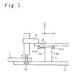
- FIG. 7 is a schematic diagram showing the end portion processing apparatus 2 according to the present embodiment.
- the structures of the guide member 4 and the cutter supporting member 15 are changed from those of the first embodiment. Because the other structures in the first embodiment can be adopted as they are, a detailed description is omitted.
- the first surface 19 and the second surface 20 are prepared for the guide member 4.
- the first surface 19 and the second surface 20 turn the directions opposing to each other in the Y-direction.
- a pair of abutment members 21 (21-1, 21-2) are provided for the cutter supporting member 15.
- the pair of abutment members 21 are arranged in a position so as to put the guide member 4 between them in the Y-direction.
- Each of the abutment members 21 is a roller member.
- a distance between the abutment members 21 (21-1, 21-2) is larger by the clearance c than the distance between the first surface 19 and the second surface 20.
- the air cylinder 17 pulls the cutter supporting member 15 in case of going forth.
- one 21-2 of the abutment members abuts to the first surface 19 of the guide member 4.
- the air cylinder 17 pushes the cutter supporting member 15.
- the other abutment member 21-1 abuts to the second surface 20. That is, the position of the end mill cutter 9 can be changed in the Y-direction by the air cylinder 17.
- FIG. 8 is a diagram schematically showing the end portion processing apparatus 2 according to the present embodiment. It should be noted that for convenience of explanation, only a part is illustrated in FIG. 8 to explain the present embodiment, and the illustration of the running unit 8 and so on is omitted. In the following description, a part where there is not any explanation is the same as that of the above embodiments.
- a pin supporting section 24 is provided for the main surface of the plate member 3 in place of the Y-direction pin positioning member 5 (see FIG. 2 ).
- the pin supporting section 24 is composed of a pair of first pin supporting sections 22 and a pair of second pin supporting sections 23.
- the pair of first pin supporting sections 22 and the pair of second pin supporting sections 23 are formed as a concave section and are configured as a support of pin members 25.
- the pair of the first pin supporting sections 22 and the pair of the second pin supporting sections 23 are provided on different positions in the Y-direction.
- the pair of the second pin supporting sections 23 is provided for the position nearer to the guide member 4 than the pair of the first pin supporting sections 22.
- the pin supporting section 24 functions in case of going forth and in case of going back as a Y-direction position changing mechanism in which the position of the end mill cutter 9 is changed in the Y-direction.
- the hang tab 34 is cut in case of going forth and the finish processing is performed in case of going back.
- the position of the end portion processing apparatus 2 is shifted as a whole in the Y-direction. Therefore, like the previous embodiments, the clearance c does not have to be provided between the cutter supporting member 15 and the guide member 4. Also, it does not always need the air cylinder 17.
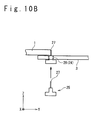
- FIG. 10A is a schematic diagram showing the pin supporting section 24 of the present embodiment.
- a pair of pin insertion holes 28 are provided for the pin supporting section 24. It should be noted that only one of the pair of pin insertion holes is drawn in FIG. 10A .
- the pin member 25 is inserted into the pin insertion hole 28.
- the pin member 25 has an abutment section 27 which penetrates or passes through the pin insertion hole 28 and protrudes on the main surface of the plate member 3.
- a pipe-shape color (pipe member 29) is attached to this abutment section 27 detachably.
- the pin member 25 with the pipe member 29 attached is inserted in the pin insertion hole 28 (see FIG. 10A ). Then, the pin member 25 is pushed to the end of the work material 1 and a position of the plate member 3 in the Y-direction is determined. In this case, the pin member 25 abuts to the work material 1 by the pipe member 29. After that, like the third embodiment, the operation in case of going forth is executed.
- the position of the end mill cutter 9 becomes able to be changed in the Y-direction in case of going forth and in case of going back, like the third embodiment.
- the work material 1 is cut in case of going forth, and the finish processing is performed in case of going back.
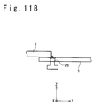
- FIG. 11A is a schematic diagram showing the pin member 25 according to the present embodiment.
- the pin member 25 has a base section 32, a large diameter section 31 and a small diameter section 33.
- the outer diameter of the base section 32 is larger than the pin insertion hole 28.
- the large diameter section 31 extends upwardly to protrude from the base section 32 and is formed to have the size possible to be inserted in the pin insertion hole 28.
- the small diameter section 33 extends upwardly to protrude from the large diameter section 31 and the outer diameter thereof is smaller than the large diameter section 31.
- the height of the large diameter section 31 is larger than the board thickness of the plate member 3.
- the pin member 25 is inserted in the pin insertion hole 28 (see FIG. 11A ). At this time, the pin member 25 inserted so that the base section 32 is brought contact with the back surface of the plate member 3. A part of the large diameter section 31 protrudes from the main surface of the plate member 3. In this condition, the pin member 25 is abutted to the end of the work material 1 to position the plate member 3. At this time, the pin member 25 abuts with the work material 1 at the large diameter section 31. After that, like the fourth embodiment, the operation in case of going forth is executed.
- the insertion depth of the pin member 25 is changed. Specifically, as shown in FIG. 11B , the insertion depth is changed so that the small diameter section 33 protrudes from the main surface of the plate member 3. After that, the pin member 25 is abutted to the end of the work material 1 again to position the plate member 3. In this case, the pin member 25 is brought contact with the work material 1 in the small diameter section 33. Due to a difference between the large diameter section 31 and the small diameter section 33 in the outer diameter, the plate member 3 goes into a portion under the work material 1 deeply. As a result, the position of the end mill cutter 9 can be changed in the Y-direction in case of going forth and in case of going back, like the fourth embodiment. Like the previous embodiments, the work material 1 is cut in case of going forth, and the finish processing is carried out in case of going back.
Landscapes
- Engineering & Computer Science (AREA)
- Mechanical Engineering (AREA)
- Automation & Control Theory (AREA)
- Milling Processes (AREA)
- Jigs For Machine Tools (AREA)
- Machine Tool Copy Controls (AREA)
- Milling, Drilling, And Turning Of Wood (AREA)
- Control Of Cutting Processes (AREA)
Abstract
Description
- The present invention relates to an end portion processing apparatus.
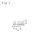
- A technique of processing an end portion of a work material to a desired shape is known. For example, as shown in
FIG. 1 , in the process of the manufacture of a main wing panel of an aircraft, a plurality ofconveyance hang tabs 101 are prepared for the end portion of themain wing panel 100. When themain wing panel 100 is conveyed, themain wing panel 100 is suspended by use of the plurality ofhang tabs 101. Thehang tabs 101 are finally unnecessary, and are cut and detached from themain wing panel 100. In the cutting, it is required to process the end portion of themain wing panel 100 to be smooth. - In order to process the end portion of the work material to be smooth, a technique of cutting an unnecessary portion and using a sandpaper to polish the end portion is thought of. However, the polishing process takes time and the processing cost increases.
- In relation to the above description, a method of processing the end portion of a carbon fiber reinforced plastic laminate board and so on is disclosed in Patent Literature 1 (Japanese Patent Publication (
JP 2010-94800A Patent Literature 1. - [Patent Literature 1]
JP 2010-94800A - According to
Patent Literature 1, the position control of the work material is performed by using the NC control machine. However, when the work material is a large-scaled product such as the main wing panel of the aircraft, it is not practical to change the position of the work material in the processing. - Therefore, the present invention may provide an end portion processing apparatus which can process an end portion of a work material without moving the work material, to have a smooth shape.
- The end portion processing apparatus according to the present invention is an end portion processing apparatus which processes an end portion of a work material arranged on the XY-plane. This end portion processing apparatus includes an X-direction driving unit which allows a back-and-forth movement along an X-direction; a cutter supporting member which is driven by said X-direction driving unit, is able to move in a Y-direction, and supports a cutter member extending in a Z-direction which is perpendicular to the XY-plane; a guide member which has a shape matching to a processing planned shape when seeing from the Z-direction, and guides said cutter supporting member such that said cutter member moves to follow the processing planned shape; and a Y-direction position changing mechanism which changes the position in the Y-direction of said cutter supporting member to the work material. The Y-direction position changing mechanism changes the position of said cutter supporting member such that said cutter supporting member runs on further inner side in case of going back than in case of going forth.
- According to the present invention, when the X-direction driving unit operates, a cutter supporting member is guided to follow a guide member. As a result, the cutter member moves to match to a processing planned shape. Thus, it is possible to process the end portion of the work material without moving the work material, to have a desired shape.
- In addition, a position of the cutter supporting member in a Y-direction is changed so that the cutter member moves in a further inside of the work material in case of going back than in case of going forth, by the Y-direction position changing mechanism. Thus, it is possible to roughly process the end portion of the work material is in case of going forth and perform the finish processing in case of going back. The cutter supporting member is subjected to back-and-forth movement by the X-direction driving unit, and as a result, the end portion of the work material can be processed to have a smooth shape.
- According to the present invention, the end portion processing apparatus is provided which can processes the end portion of the work material without moving the work material, to have a smooth shape.
-
-
FIG. 1 is a diagram showing a conventional example of a main wing panel; -
FIG. 2 is a perspective view schematically showing an end portion processing apparatus according to a first embodiment; -
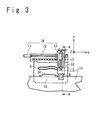
FIG. 3 is a schematic diagram when seeing the end portion processing apparatus from the Z-direction; -
FIG. 4 is a schematic diagram when seeing the end portion processing apparatus from the X-direction; -
FIG. 5 is an expanded view showing a roller member; -
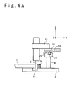
FIG. 6A is a schematic diagram showing a position of the cutter supporting member in case of going forth; -
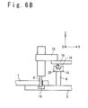
FIG. 6B is a schematic diagram showing the position of the cutter supporting member in case of going back; -
FIG. 7 is a schematic diagram showing the end portion processing apparatus according to a second embodiment; -
FIG. 8 is a diagram showing the end portion processing apparatus according to a third embodiment; -
FIG. 9 is a schematic diagram showing a structure of a pin supporting section; -
FIG. 10A is a schematic diagram showing the pin supporting section in a fourth embodiment; -
FIG. 10B is a schematic diagram showing the pin supporting section in the fourth embodiment; -
FIG. 11A is a schematic diagram showing a pin member according to a fifth embodiment; and -
FIG. 11B is a schematic diagram showing the pin member according to the fifth embodiment. - Hereinafter, embodiments of the present invention will be described with reference to the attached drawings.
-
FIG. 2 is a perspective view schematically showing an endportion processing apparatus 2 according to a first embodiment of the present invention. The endportion processing apparatus 2 is used to process an end portion of awork material 1. - In the present embodiment, it is supposed that the
work material 1 is a main wing panel of an aircraft. Also, it is supposed that thework material 1 is CFRP (carbon fiber reinforced plastic laminate board). Thework material 1 has an almost flat platelike shape and is arranged on an XY-plane. The end portion of thework material 1 extends along an X-direction. Ahang tab 34 is provided for the end portion of thework material 1 to protrude into a Y-direction. - In the present embodiment, the end
portion processing apparatus 2 is used to cut thehang tab 34. The endportion processing apparatus 2 has aflat plate member 3 and a running unit 8. Theplate member 3 is provided to support the running unit 8 and is fixed to thework material 1. The running unit 8 is fixed on the main surface of theplate member 3 by fixation pins 10. The running unit 8 supports anend mill cutter 9 extending to a Z-direction and has a function to move theend mill cutter 9. By moving theend mill cutter 9, thehang tab 34 is cut and the end portion of thework material 1 is processed. -
FIG. 3 is a schematic diagram when seeing the endportion processing apparatus 2 from the Z-direction. Also,FIG. 4 is a schematic diagram when seeing the endportion processing apparatus 2 from the X-direction. Referring toFIG. 2 to FIG. 4 , the structure of the endportion processing apparatus 2 will be described in detail. - First, the structure of the
plate member 3 will be described. - A part of the
plate member 3 is located under thework material 1 to overlap with thework material 1. Theplate member 3 is fixed to thework material 1 by using clamps (not shown) and so on. Aguide member 4, aditch 18, a pair of Y-directionpositioning pin members 5 and aX-direction positioning hole 7 are provided on the main surface of theplate member 1. It should be noted that the Y-directionpositioning pin member 5 and theX-direction positioning hole 7 are illustrated only inFIG. 2 , and inFIG. 3 , illustration of them is omitted. - The pair of the Y-direction
positioning pin members 5 and theX-direction positioning hole 7 are provided to position theplate member 3. - The
X-direction positioning hole 7 is a long hole extending along the Y-direction. A reference hole to position theplate member 3 in the Y-direction is provided for thework material 1. In the positioning, the reference hole is overlapped with theX-direction positioning hole 7 and the X-directionpositioning pin member 6 is inserted. Thus, theplate member 3 is positioned in the X-direction with respect to the work material. - On the other hand, the pair of the Y-direction
positioning pin members 5 are provided for end portions of theplate member 3 in the X-direction and rises upwardly from the main surface of theplate member 3. By pushing the Y-directionpositioning pin member 5 against the end portion of thework material 1, theplate member 3 is positioned in the Y-direction. - If the
plate member 3 is fixed to thework material 1 by using the clamps and so on after theplate member 3 is positioned in the X-direction and the Y-direction, it is possible to attach theplate member 3 to a desired position. - The
guide member 4 is provided to guide theend mill cutter 9 to follow a processing planned shape. Theguide member 4 has a guide ditch which has a shape corresponding to the processing planned shape. - A
ditch 18 is provided to prevent theend mill cutter 9 from interfering with theplate member 3. As shown inFIG. 4 , the tip portion of theend mill cutter 9 is inserted into theditch 18 and does not interfere with theplate member 3. - Next, the structure of the running unit 8 will be described in detail. As shown in
FIG. 3 , the running unit 8 has anX-direction driving unit 14, acutter supporting member 15 and an air cylinder 17 (the pushing mechanism). - The
X-direction driving unit 14 is composed of amotor 11, a runningaxis member 12 and anX-direction moving member 13. The runningaxis member 12 extends along the X-direction. The runningaxis member 12 is connected to themotor 11 and themotor 11 rotates it. TheX-direction moving member 13 is attached to the runningaxis member 12 and moves along the X-direction as the runningaxis member 12 turns. That is, by rotating the runningaxis member 12 by themotor 11, it is possible to move theX-direction moving member 13 along the X-direction. As themotor 11, a servo motor is used. Themotor 11 drives theX-direction moving member 13 to go back and forth. Also, themotor 11 is connected with a controller (not shown). A program for the running speed control is installed in the controller. The running speed of theX-direction moving member 13 is controlled by the program for the running speed control and is controlled according to the running position of theX-direction moving member 13. - Also, as shown in
FIG. 4 , arail member 35 extending along the Y-direction is attached to theX-direction moving member 13. - The
cutter supporting member 15 is provided to support theend mill cutter 9. As shown inFIG. 4 , thecutter supporting member 15 is arranged on arail member 35 and is supported by theX-direction moving member 13 through therail member 35. Thecutter supporting member 15 is movable into the Y-direction along therail member 35. - Also, the
cutter supporting member 15 has aroller member 16. Theroller member 16 is inserted in the guide ditch provided for theguide member 4. Theroller member 16 is installed to be able to roll in the guide ditch. When theX-direction moving member 13 moves along the X-direction, theroller member 16 rolls in the guide ditch. As a result, thecutter supporting member 15 is guided by the guide ditch and theend mill cutter 9 moves to match to the processing planned shape. Thus, the end portion of thework material 1 is processed. - Here, in the present embodiment, the structure of the
roller member 16 is devised.FIG. 5 is a diagram showing by magnifying theroller member 16. The diameter of theroller member 16 in the Y-direction is smaller than the width of the guide ditch as shown inFIG. 5 , and a clearance c is generated between theroller member 16 and the side wall of the guide ditch. - An
air cylinder 17 is provided to change the position of thecutter supporting member 15 to thework material 1 in the Y-direction. As shown inFIG. 4 , theair cylinder 17 is connected to theX-direction moving member 13 at one end and is connected to thecutter supporting member 15 at the other end. Theair cylinder 17 applies a force in the Y-direction to thecutter supporting member 15. - Next, a method of operating the end
portion processing apparatus 2 according to the present embodiment will be described. - First, the
plate member 3 is positioned by using the Y-directionpositioning pin member 5 and theX-direction positioning hole 7. After the positioning, theplate member 3 is fixed on thework material 1 by using clamps and so on. Next, the running unit 8 is fixes on theplate member 3. - Next, the
X-direction driving unit 14 drives theX-direction moving member 13 to move in the X-direction so as to allow back-and-forth movement along the X-direction. - At this time, the
air cylinder 17 applies tensile force to thecutter supporting member 15 in case of going forth.FIG. 6A is a schematic diagram showing the position of thecutter supporting member 15 in case of going forth. When thecutter supporting member 15 is pulled to the side of theair cylinder 17 as shown inFIG. 6A , theroller member 16 abuts to one of the side walls of the guide ditch (a first surface 19). As a result, theroller member 16 follows one of the side walls and moves along it. Because the guide ditch has a shape corresponding to the processing planned shape, theend mill cutter 9 supported by thecutter supporting member 15 moves according to the processing planned shape. As a result, thehang tab 34 is cut out from thework material 1. - On the other hand, the
air cylinder 17 applies pushing force to thecutter supporting member 15 to in case of going back.FIG. 6B is a schematic diagram showing the position of thecutter supporting member 15 in in case of going back. When thecutter supporting member 15 is pushed by theair cylinder 17 as shown inFIG. 6B , theroller member 16 abuts to the other side wall (a second surface 20) of the guide ditch. As a result, theroller member 16 follows the other side wall and moves. Therefore, in case of going back, theend mill cutter 9 moves along the inside of theplate member 3 by a clearance c (seeFIG. 5 ) than in case of going forth. Therefore, if the clearance c is set to a suitable value, the end portion of thework material 1 cut in case of going forth can be processed to perform finish processing in case of going back. - As described above, according to the present embodiment, because the
guide member 4 is provided, thecutter supporting member 15 can be guided along the processing planned shape. Thus, the end portion of thework material 1 can be processed without moving the work material. Also, it is not necessary to use a large-sized apparatus like an NC processing machine, and the end portion of thework material 1 can be easily processed. - In addition, in the present embodiment, the diameter of the
roller member 16 is set smaller than the width of the guide ditch. Thus, theroller member 16 is pushed to one of the side walls in case of going forth by theair cylinder 17 and theroller member 16 is pushed to the other side wall in case of going back. That is, the line which theend mill cutter 9 moves can be easily changed by theair cylinder 17 in case of going back and forth. As a result, both of rough processing and finish processing can be performed only by theX-direction driving unit 14 operating in case of going back-and-forth. - Also, in the present embodiment, the running unit 8 is attached to the
plate member 3 detachably. That is, it is possible to separate theguide member 4 and the running unit 8. Many hangtabs 34 are generally provided for the main wing panel of the aircraft. The processing shape sometimes depends on the positions of thehang tabs 34. Even in such a case, if the guide member 4 (the plate member 3) is prepared previously every processing shape, a different portion can be processed by using the identical running unit 8. Also, thecutter supporting member 15 can be easily separated intoparts hang tab 34, movement speed in the X-direction can be set flexibly by a controller (seeFIG. 4 ). - Also, it is desirable that in case of going back, the X-direction driving unit drives the
X-direction moving member 13 to move in the X-direction at higher speed than in case of going forth. Theend mill cutter 9 cuts thehang tab 34 in case of going forth. Therefore, the resistance which is applied to theend mill cutter 9 in processing becomes large. When theX-direction moving member 13 is moved at high speed in case of going forth, it is easy for the shape of the end portion of thework material 1 to become rough. Therefore, in case of going forth, theX-direction moving member 13 is moved at a lower speed. On the other hand, the resistance which is applied to theend mill cutter 9 in case of going back is smaller than in case of going forth. Therefore, even if theX-direction moving member 13 is moved at high speed, it is possible to obtain a sufficiently smooth shape after the processing. Also, by moving theX-direction moving member 13 at high speed in case of going back, it is possible to reduce processing time of thework material 1. - It should be noted that in the present embodiment, a case that the
work material 1 is the main wing panel made from CFRP has been described. However, thework material 1 is not limited to the main wing panel made from CFRP, and the endportion processing apparatus 2 of the present embodiment can be applied to anotherwork material 1. Also, the main wing panel made from CFRP is large-sized and it is required that it has a smooth shape after the processing. From these viewpoints, the endportion processing apparatus 2 according to the present embodiment can be used to suitably process the main wing panel made from CFRP. It should be noted that it is desirable that the clearance c is set to about 0.5 mm when thework material 1 is the main wing panel made from CFRP. - Next, a second embodiment will be described.
FIG. 7 is a schematic diagram showing the endportion processing apparatus 2 according to the present embodiment. In the present embodiment, the structures of theguide member 4 and thecutter supporting member 15 are changed from those of the first embodiment. Because the other structures in the first embodiment can be adopted as they are, a detailed description is omitted. - As shown in
FIG. 7 , in the present embodiment, thefirst surface 19 and thesecond surface 20 are prepared for theguide member 4. Thefirst surface 19 and thesecond surface 20 turn the directions opposing to each other in the Y-direction. On the other hand, a pair of abutment members 21 (21-1, 21-2) are provided for thecutter supporting member 15. The pair of abutment members 21 are arranged in a position so as to put theguide member 4 between them in the Y-direction. Each of the abutment members 21 is a roller member. Here, a distance between the abutment members 21 (21-1, 21-2) is larger by the clearance c than the distance between thefirst surface 19 and thesecond surface 20. - In the present embodiment, like the first embodiment, the air cylinder 17 (not illustrated in
FIG. 7 ) pulls thecutter supporting member 15 in case of going forth. By this, one 21-2 of the abutment members abuts to thefirst surface 19 of theguide member 4. On the other hand, in case of going back, theair cylinder 17 pushes thecutter supporting member 15. By this, the other abutment member 21-1 abuts to thesecond surface 20. That is, the position of theend mill cutter 9 can be changed in the Y-direction by theair cylinder 17. Thus, like the first embodiment, it possible to perform rough processing in case of going forth and finish processing in case of going back. - Next, a third embodiment will be described. In the above embodiments, relative position relation between the
cutter supporting member 15 and theguide member 4 is changed in the Y-direction, and the position of theend mill cutter 9 to thework material 1 is changed in the Y-direction. On the other hand, in the present embodiment, the position of theplate member 3 to thework material 1 is changed in the Y-direction and the position of theend mill cutter 9 is changed in the Y-direction. -
FIG. 8 is a diagram schematically showing the endportion processing apparatus 2 according to the present embodiment. It should be noted that for convenience of explanation, only a part is illustrated inFIG. 8 to explain the present embodiment, and the illustration of the running unit 8 and so on is omitted. In the following description, a part where there is not any explanation is the same as that of the above embodiments. - As shown in
FIG. 8 , in the present embodiment, apin supporting section 24 is provided for the main surface of theplate member 3 in place of the Y-direction pin positioning member 5 (seeFIG. 2 ). Thepin supporting section 24 is composed of a pair of firstpin supporting sections 22 and a pair of secondpin supporting sections 23. The pair of firstpin supporting sections 22 and the pair of secondpin supporting sections 23 are formed as a concave section and are configured as a support ofpin members 25. Here, the pair of the firstpin supporting sections 22 and the pair of the secondpin supporting sections 23 are provided on different positions in the Y-direction. Specifically, the pair of the secondpin supporting sections 23 is provided for the position nearer to theguide member 4 than the pair of the firstpin supporting sections 22. - Next, a method of operating the end
portion processing apparatus 2 according to the present embodiment will be described. - (a) of
FIG. 9 is a schematic diagram showing the structure of thepin supporting section 24 in case of going forth. In the present embodiment, when theplate member 3 is positioned, thepin members 25 are installed in the pair of the firstpin supporting sections 22. Thepin members 25 stand upwardly from theplate member 3. After that, thepin members 25 abut to the end of thework material 1 so that theplate member 3 is positioned in the Y-direction. After the positioning, like the previous embodiments, theplate member 3 is fixed to thework material 1 by using the clamps and so on. Moreover, an operation in case of going forth is executed by theX-direction driving unit 14, to cut thehang tab 34. - (b) of
FIG. 9 is a schematic diagram showing the structure of thepin supporting section 24 in case of going back. When the operation in case of going forth ends, the clamps and so on are removed. Then, thepin members 25 are moved to the pair of the secondpin supporting sections 23 from the pair of the firstpin supporting sections 22. Again, theplate member 3 is positioned so that thepin members 25 abut to the end portion of thework material 1. Moreover, theplate member 3 is fixed by the clamps and so on. As shown by (b) ofFIG. 9 , theplate member 3 goes under thework material 1 more deeply than in case of gong forth. As a result, the position of theplate member 3 is shifted in an inside direction as a whole in the Y-direction, and the position of the end mill cutter 9 (not illustrated inFIG. 9 ) is changed into the inside direction. After that, an operation in case of going back is executed by theX-direction driving unit 14. Thus, the finish processing is performed. - In the present embodiment, the
pin supporting section 24 functions in case of going forth and in case of going back as a Y-direction position changing mechanism in which the position of theend mill cutter 9 is changed in the Y-direction. As a result, like the previous embodiments, thehang tab 34 is cut in case of going forth and the finish processing is performed in case of going back. - It should be noted that in the present embodiment, the position of the end
portion processing apparatus 2 is shifted as a whole in the Y-direction. Therefore, like the previous embodiments, the clearance c does not have to be provided between thecutter supporting member 15 and theguide member 4. Also, it does not always need theair cylinder 17. - Next, a fourth embodiment will be described. In the present embodiment, the structures of the
pin supporting section 24 and thepin member 25 are changed from those of the third embodiment. Because the other components are the same as those of the third embodiment, a detailed description is omitted. -
FIG. 10A is a schematic diagram showing thepin supporting section 24 of the present embodiment. In the present embodiment, a pair of pin insertion holes 28 are provided for thepin supporting section 24. It should be noted that only one of the pair of pin insertion holes is drawn inFIG. 10A . Thepin member 25 is inserted into thepin insertion hole 28. Here, thepin member 25 has anabutment section 27 which penetrates or passes through thepin insertion hole 28 and protrudes on the main surface of theplate member 3. A pipe-shape color (pipe member 29) is attached to thisabutment section 27 detachably. - Next, a method of operating the end
portion processing apparatus 2 according to the present embodiment will be described. - In the present embodiment, first, when the
plate member 3 is positioned in the Y-direction, thepin member 25 with thepipe member 29 attached is inserted in the pin insertion hole 28 (seeFIG. 10A ). Then, thepin member 25 is pushed to the end of thework material 1 and a position of theplate member 3 in the Y-direction is determined. In this case, thepin member 25 abuts to thework material 1 by thepipe member 29. After that, like the third embodiment, the operation in case of going forth is executed. - On the other hand, when the operation in case of going forth ends, the
pin member 25 is removed and thepipe member 29 is removed from thepin member 25. Then, thepin member 25 withpipe member 29 removed as shown inFIG. 10B is again inserted in thepin insertion hole 28. After that, thepin member 25 abuts to the end of thework material 1 again and theplate member 3 is positioned in the Y-direction. In this case, because thepipe member 29 is removed from thepin member 25, theplate member 3 is shifted into the inside direction for the thickness ofpipe member 29 in case of going back. That is, theplate member 3 is shifted inside in the Y-direction. As a result, the position of theend mill cutter 9 becomes able to be changed in the Y-direction in case of going forth and in case of going back, like the third embodiment. Like the previous embodiments, thework material 1 is cut in case of going forth, and the finish processing is performed in case of going back. - Next, a fifth embodiment will be described. In the present embodiment, the structure of the
pin member 25 is changed from that of the fourth embodiment. Because the other structures are the same as those of the fourth embodiment, a detailed description is omitted. -
FIG. 11A is a schematic diagram showing thepin member 25 according to the present embodiment. As shown inFIG. 11A , thepin member 25 has abase section 32, alarge diameter section 31 and asmall diameter section 33. The outer diameter of thebase section 32 is larger than thepin insertion hole 28. Thelarge diameter section 31 extends upwardly to protrude from thebase section 32 and is formed to have the size possible to be inserted in thepin insertion hole 28. Thesmall diameter section 33 extends upwardly to protrude from thelarge diameter section 31 and the outer diameter thereof is smaller than thelarge diameter section 31. Also, the height of thelarge diameter section 31 is larger than the board thickness of theplate member 3. - Next, a method of operating the end
portion processing apparatus 2 according to the present embodiment will be described. - In the present embodiment, first, when the
plate member 3 is positioned in the Y-direction, thepin member 25 is inserted in the pin insertion hole 28 (seeFIG. 11A ). At this time, thepin member 25 inserted so that thebase section 32 is brought contact with the back surface of theplate member 3. A part of thelarge diameter section 31 protrudes from the main surface of theplate member 3. In this condition, thepin member 25 is abutted to the end of thework material 1 to position theplate member 3. At this time, thepin member 25 abuts with thework material 1 at thelarge diameter section 31. After that, like the fourth embodiment, the operation in case of going forth is executed. - When the operation in case of going forth ends, the insertion depth of the
pin member 25 is changed. Specifically, as shown inFIG. 11B , the insertion depth is changed so that thesmall diameter section 33 protrudes from the main surface of theplate member 3. After that, thepin member 25 is abutted to the end of thework material 1 again to position theplate member 3. In this case, thepin member 25 is brought contact with thework material 1 in thesmall diameter section 33. Due to a difference between thelarge diameter section 31 and thesmall diameter section 33 in the outer diameter, theplate member 3 goes into a portion under thework material 1 deeply. As a result, the position of theend mill cutter 9 can be changed in the Y-direction in case of going forth and in case of going back, like the fourth embodiment. Like the previous embodiments, thework material 1 is cut in case of going forth, and the finish processing is carried out in case of going back. - As described above, the first to fifth embodiments of the present invention have been described. It should be noted that these embodiments are not independent each other and can be combined in a range where there is no contradiction.
- This application claims a priority on convention based on Japanese patent application No.
JP 2011-000792 filed on January 5, 2011
Claims (15)
- An end portion processing apparatus, which processes an end portion shape of a work material arranged on an XY-plane, comprising:an X-direction driving unit which allows a back-and-forth movement along an X-direction;a cutter supporting member driven by said X-direction driving unit, being able to move in a Y-direction, and supporting a cutter member extending in a Z-direction which is perpendicular to the XY-plane;a guide member which has a shape matching to a processing planned shape when seeing from the Z-direction, and guides said cutter supporting member such that said cutter member moves to follow the processing planned shape; anda Y-direction position changing mechanism which changes the position in the Y-direction of said cutter supporting member to the work material,wherein said Y-direction position changing mechanism changes the position of said cutter supporting member such that said cutter supporting member moves on further inner side of the work material in case of going back than in case of going forth.
- The end portion processing apparatus according to claim 1. wherein said guide member has a first surface and a second surface, and
wherein said Y-direction position changing mechanism comprises a pushing mechanism which pushes said cutter member against said first surface in case of going forth, and pushes said cutter supporting member against said second surface in case of going back. - The end portion processing apparatus according to claim 2, wherein said guide member has a guide ditch extending to match to the processing planned shape,
wherein said cutter supporting member comprises an insertion member which is inserted in said guide ditch,
wherein a width of said insertion member in the Y-direction is smaller than a width of said guide ditch, and
wherein said first surface is realized by one of the side walls of said guide ditch, and said second surface is realized by the other side wall of said guide ditch. - The end portion processing apparatus according to claim 3, wherein said insertion member comprises a roller member that rolls in said guide ditch.
- The end portion processing apparatus according to claim 2, wherein said first surface and said second surface turn to opposite directions to each other with respect to the Y-direction,
wherein said cutter supporting member comprises a pair of abutment members provided to put said guide member between said abutment members in the Y-direction, and
a distance between said first surface and said second surface is smaller than a distance between said abutment members. - The end portion processing apparatus according to any of claims 2 to 5, wherein said pushing mechanism comprises an air cylinder connected to said X-direction driving unit at one end and connected to said cutter supporting member at the other end.
- The end portion processing apparatus according to claim 1, further comprising:a plate member arranged to partially overlap with said work material,wherein said cutter supporting member is arranged on a main surface of said plate member,wherein a Y-direction position changing mechanism comprises:a pin supporting section provided in the main surface of said plate member;pin members supported detachably by said pin supporting section, extending upwardly from the main surface of said plate member, and abutting with an end of the work material to position said plate member in the Y-direction,wherein said pin supporting section comprises a first pin supporting section and a second pin supporting section which are arranged in different positions in the Y-direction, andwherein said pin members are supported by said first pin supporting section in case of going forth, and said pin members are supported by said second pin supporting section in case of going back.
- The end portion processing apparatus according to claim 1, further comprises:a plate member arranged to partially overlap with the work material,wherein said cutter supporting member is arranged on said plate member,wherein said Y-direction position changing mechanism comprises:pin insertion holes provided for said plate member; andpin members inserted in said pin insertion holes to protrude from said plate member, and abutting to the end of the work material to position said plate member in the Y-direction,wherein said pin member comprises:an abutment section which abuts to the end of the work material in case of going back; anda circular cylinder member attached to cover said abutment section in case of going forth.
- The end portion processing apparatus according to claim 1, further comprising a plate member arranged to partially overlap with said work material,
wherein said cutter supporting member is arranged on said plate member,
wherein said Y-direction position changing mechanism comprises:pin insertion holes provided for said plate member; andpin members inserted in said pin insertion holes to protrude from said plate member and abutting to the end of the work material to position said plate member in the Y-direction,wherein said pin member comprises:a large diameter section and a small diameter section,wherein said pin member is inserted in said pin insertion hole in such a depth that said large diameter section abuts to the end of the work material in case of going forth, andin case of going back, said pin member is inserted in said pin insertion hole in such a depth that said small diameter section abuts to the end of the work material. - The end portion processing apparatus according to any of claims 1 to 9, wherein said cutter member comprises an end mill cutter.
- The end portion processing apparatus according to any of claims 1 to 10, wherein the work material is a main wing of an aircraft.
- The end portion processing apparatus according to any of claims 1 to 11, wherein the work material is a carbon fiber reinforced plastic laminate material.
- The end portion processing apparatus according to any of claims 1 to 12, wherein said X-direction driving unit comprises a servo motor.
- The end portion processing apparatus according to any of claims 1 to 13, wherein said X-direction driving unit and said guide member are separable from each other.
- The end portion processing apparatus according to any of claims 1 to 14, wherein said X-direction driving unit operates at a higher speed in case of going back than in case of going forth.
Applications Claiming Priority (2)
| Application Number | Priority Date | Filing Date | Title |
|---|---|---|---|
| JP2011000792A JP5725868B2 (en) | 2011-01-05 | 2011-01-05 | End processing equipment |
| PCT/JP2011/080168 WO2012093617A1 (en) | 2011-01-05 | 2011-12-27 | Edge working apparatus |
Publications (3)
| Publication Number | Publication Date |
|---|---|
| EP2662171A1 true EP2662171A1 (en) | 2013-11-13 |
| EP2662171A4 EP2662171A4 (en) | 2016-09-14 |
| EP2662171B1 EP2662171B1 (en) | 2017-09-13 |
Family
ID=46457475
Family Applications (1)
| Application Number | Title | Priority Date | Filing Date |
|---|---|---|---|
| EP11855033.4A Not-in-force EP2662171B1 (en) | 2011-01-05 | 2011-12-27 | Edge working apparatus |
Country Status (7)
| Country | Link |
|---|---|
| US (1) | US9302333B2 (en) |
| EP (1) | EP2662171B1 (en) |
| JP (1) | JP5725868B2 (en) |
| CN (1) | CN103153509B (en) |
| BR (1) | BR112013006527B1 (en) |
| CA (1) | CA2812994C (en) |
| WO (1) | WO2012093617A1 (en) |
Families Citing this family (17)
| Publication number | Priority date | Publication date | Assignee | Title |
|---|---|---|---|---|
| CN103878420A (en) * | 2012-12-22 | 2014-06-25 | 中航贵州飞机有限责任公司 | Application method of carving machine in milling processing |
| CN104174909A (en) * | 2013-05-23 | 2014-12-03 | 广州新成机械技术有限公司 | Portable milling machine |
| CN104028813B (en) * | 2014-07-03 | 2016-06-22 | 涂瑞强 | A kind of using method of Milling Process assembly |
| JP6542591B2 (en) * | 2015-06-08 | 2019-07-10 | 株式会社Subaru | Machining apparatus and machining method |
| KR101641029B1 (en) | 2015-12-24 | 2016-07-20 | 이현진 | Uneven structure fabricating gig and it used uneven structure fabricating method |
| KR101639537B1 (en) * | 2015-12-24 | 2016-07-14 | 이현진 | Woodwork table and multiple-purpose woodwork machine with it |
| CN105598510B (en) * | 2016-01-08 | 2018-03-13 | 湖北善德民用科技有限公司 | A kind of semi-automatic milling long arc-shaped holes device of working of plastics |
| EP3542953A4 (en) * | 2016-11-18 | 2020-07-08 | Agc Inc. | DEVICE FOR PROCESSING A CURVED PLATE AND METHOD FOR PRODUCING A CURVED PLATE WITH A PROCESSED EXTERNAL CIRCUIT |
| WO2019092797A1 (en) * | 2017-11-07 | 2019-05-16 | 三菱重工業株式会社 | Processing apparatus and processing method |
| CN108581727A (en) * | 2018-05-18 | 2018-09-28 | 无锡大燕科技有限公司 | A kind of grinding device |
| CN110039102A (en) * | 2019-04-10 | 2019-07-23 | 广东绿缔智能冷链科技股份有限公司 | Planer for processing curved surface of base of display refrigerator |
| CN110509038B (en) * | 2019-08-01 | 2021-03-30 | 广东万盛兴智能技术研究院有限公司 | Track seeking mechanism |
| CN111001863A (en) * | 2019-12-24 | 2020-04-14 | 浦江吉树机械科技有限公司 | Fixed metal block milling device |
| CN110877282A (en) * | 2019-12-25 | 2020-03-13 | 郝松涛 | Automatic profiling sanding or polishing equipment for pipe bends |
| CN111940802B (en) * | 2020-08-17 | 2022-10-18 | 沈阳飞机工业(集团)有限公司 | Milling tool for margin of aluminum alloy skin of airplane |
| CN112757407A (en) * | 2021-01-15 | 2021-05-07 | 孙晓翠 | Intelligence panel processingequipment |
| CN113857574B (en) * | 2021-10-13 | 2025-12-26 | 深圳市万宝隆科技发展有限公司 | A vertical saw |
Family Cites Families (27)
| Publication number | Priority date | Publication date | Assignee | Title |
|---|---|---|---|---|
| US1853554A (en) * | 1929-07-29 | 1932-04-12 | Alfred A Dennis | Veneer jointer |
| US2037635A (en) * | 1933-12-30 | 1936-04-14 | Pratt & Whitney Co | Profiling machine |
| US2664122A (en) * | 1952-05-08 | 1953-12-29 | Sr Matthew E Allen | Pattern lathe |
| US2825270A (en) * | 1954-10-28 | 1958-03-04 | Western Electric Co | Adjustable tracing device for machines |
| DE2164786A1 (en) * | 1970-12-28 | 1972-09-14 | Fuji Photo Film Co Ltd | Method and device for cutting the |
| US3865162A (en) * | 1972-03-17 | 1975-02-11 | Zuckermann Kg Maschf | Apparatus for shaping a wooden workpiece according to a template configuration |
| US3910159A (en) * | 1974-02-15 | 1975-10-07 | Floyd R Gladwin | Apparatus for forming large radius, compound curved surfaces upon large plate-like workpieces |
| US4061077A (en) | 1977-01-06 | 1977-12-06 | Gladwin Floyd R | Apparatus for forming large compound curved surfaces |
| DE2915312A1 (en) * | 1979-04-14 | 1980-10-16 | Bernd Schuessler | Copying milling machine using two templates - has internal and external contours corresponding to workpiece for guiding two styli |
| US4601619A (en) * | 1984-10-25 | 1986-07-22 | Stinnett John L | Routing apparatus |
| US4836722A (en) * | 1985-08-10 | 1989-06-06 | Toyoda Gosei Co., Ltd. | Method and apparatus for removing flash of polymeric molded products |
| DE3710140A1 (en) * | 1987-03-31 | 1988-10-13 | Michelberger Stefan | Device for the automatic machining of an edge of a workpiece |
| US5560102A (en) * | 1992-10-13 | 1996-10-01 | The Boeing Company | Panel and fuselage assembly |
| JPH0733603A (en) | 1993-07-15 | 1995-02-03 | Takeda Engei Kk | Cut flower vitality retainer and method for retaining cut flower vitality |
| JP2589476Y2 (en) * | 1993-12-02 | 1999-01-27 | 新明和工業株式会社 | A router guide jig that prevents the lift of the router |
| US5562136A (en) * | 1994-11-30 | 1996-10-08 | Blackshear; Laton | Free floating router guide |
| JPH08323524A (en) * | 1995-05-29 | 1996-12-10 | Ishikawajima Harima Heavy Ind Co Ltd | Chamfering device |
| CN2301282Y (en) * | 1997-05-29 | 1998-12-23 | 胡长业 | Full-automatic convex-concave copying milling machine |
| US5967715A (en) * | 1998-06-17 | 1999-10-19 | Porper; Joseph | Engraving machine |
| JP2002370116A (en) * | 2001-06-13 | 2002-12-24 | Denso Corp | Work copying machine |
| JP2007015028A (en) * | 2005-07-05 | 2007-01-25 | Farukomu:Kk | Work processing device |
| JP2007265237A (en) * | 2006-03-29 | 2007-10-11 | Farukomu:Kk | Work correction device and work processing device |
| JP2010514582A (en) * | 2006-12-28 | 2010-05-06 | エクスアテック、エル.エル.シー. | Edge finishing system |
| JP5364955B2 (en) * | 2008-10-16 | 2013-12-11 | 株式会社ナサダ | End face processing method and apparatus of carbon fiber reinforced plastic laminate |
| JP2010194749A (en) | 2009-02-23 | 2010-09-09 | Mitsubishi Heavy Ind Ltd | Method for producing resin-base composite material |
| CA2750631A1 (en) * | 2009-03-24 | 2010-09-30 | Toray Industries, Inc. | Epoxy resin composition for fiber-reinforced composite material, prepreg, and fiber-reinforced composite material |
| JP5428564B2 (en) | 2009-06-18 | 2014-02-26 | 東洋紡株式会社 | Vehicle interior material member and vehicle interior material using the same |
-
2011
- 2011-01-05 JP JP2011000792A patent/JP5725868B2/en not_active Expired - Fee Related
- 2011-12-27 EP EP11855033.4A patent/EP2662171B1/en not_active Not-in-force
- 2011-12-27 CN CN201180049979.6A patent/CN103153509B/en not_active Expired - Fee Related
- 2011-12-27 CA CA2812994A patent/CA2812994C/en active Active
- 2011-12-27 WO PCT/JP2011/080168 patent/WO2012093617A1/en not_active Ceased
- 2011-12-27 BR BR112013006527-3A patent/BR112013006527B1/en not_active IP Right Cessation
- 2011-12-27 US US13/823,961 patent/US9302333B2/en active Active
Also Published As
| Publication number | Publication date |
|---|---|
| CN103153509A (en) | 2013-06-12 |
| WO2012093617A1 (en) | 2012-07-12 |
| CA2812994C (en) | 2015-03-24 |
| BR112013006527B1 (en) | 2020-08-04 |
| EP2662171A4 (en) | 2016-09-14 |
| EP2662171B1 (en) | 2017-09-13 |
| JP2012139802A (en) | 2012-07-26 |
| US20130202378A1 (en) | 2013-08-08 |
| JP5725868B2 (en) | 2015-05-27 |
| CA2812994A1 (en) | 2012-07-12 |
| CN103153509B (en) | 2015-06-17 |
| BR112013006527A2 (en) | 2016-08-02 |
| US9302333B2 (en) | 2016-04-05 |
Similar Documents
| Publication | Publication Date | Title |
|---|---|---|
| EP2662171B1 (en) | Edge working apparatus | |
| EP2633941B1 (en) | Laser processing device and laser processing method | |
| CN109570314B (en) | Tail feeding type spinning machine | |
| EP2145744A1 (en) | Apparatus and method for cutting panels | |
| CN108081755B (en) | An inkjet printing and cutting combination device | |
| CN101332573B (en) | Machine tool and method for machining a workpiece | |
| WO2012154086A2 (en) | Laser cutting machine and machine-readable medium | |
| EP3395483A1 (en) | Machine tool and cutting method | |
| CN209867084U (en) | Spinning machine with improved structure | |
| CN106715046B (en) | Processing Equipment | |
| KR20090122197A (en) | Apparatus, device and method for rubber-coating of cutting dies | |
| EP3967419B1 (en) | Composite working machine | |
| Wells et al. | Integrating ultrasonic cutting with high-accuracy robotic automatic fiber placement for production flexibility | |
| JP2019055432A (en) | Device and method for handling fastener | |
| JP2019136792A (en) | Composite processing machine for long material | |
| CN108032659A (en) | The dislocated double-sided engraving machine of cutter | |
| JP4623444B1 (en) | Thomson blade grooving machine | |
| JP5508688B2 (en) | Product carrying method and apparatus | |
| JP5538002B2 (en) | Work processing method and machine tool | |
| CN102873585A (en) | Processing device and processing method | |
| EP4011580A1 (en) | Machine tool | |
| CN218611200U (en) | Feeding mechanism and thin-walled tube slotting equipment | |
| KR20150010917A (en) | Laser cutting machine and machine-readable medium | |
| CN118284481A (en) | Tool moving device and wire forming machine | |
| JP2007283367A (en) | Plate production controller |
Legal Events
| Date | Code | Title | Description |
|---|---|---|---|
| PUAI | Public reference made under article 153(3) epc to a published international application that has entered the european phase |
Free format text: ORIGINAL CODE: 0009012 |
|
| 17P | Request for examination filed |
Effective date: 20130318 |
|
| AK | Designated contracting states |
Kind code of ref document: A1 Designated state(s): AL AT BE BG CH CY CZ DE DK EE ES FI FR GB GR HR HU IE IS IT LI LT LU LV MC MK MT NL NO PL PT RO RS SE SI SK SM TR |
|
| DAX | Request for extension of the european patent (deleted) | ||
| RA4 | Supplementary search report drawn up and despatched (corrected) |
Effective date: 20160817 |
|
| RIC1 | Information provided on ipc code assigned before grant |
Ipc: B23Q 3/18 20060101ALI20160810BHEP Ipc: B23C 1/16 20060101AFI20160810BHEP Ipc: B23C 1/20 20060101ALI20160810BHEP |
|
| GRAP | Despatch of communication of intention to grant a patent |
Free format text: ORIGINAL CODE: EPIDOSNIGR1 |
|
| INTG | Intention to grant announced |
Effective date: 20170526 |
|
| GRAS | Grant fee paid |
Free format text: ORIGINAL CODE: EPIDOSNIGR3 |
|
| GRAA | (expected) grant |
Free format text: ORIGINAL CODE: 0009210 |
|
| AK | Designated contracting states |
Kind code of ref document: B1 Designated state(s): AL AT BE BG CH CY CZ DE DK EE ES FI FR GB GR HR HU IE IS IT LI LT LU LV MC MK MT NL NO PL PT RO RS SE SI SK SM TR |
|
| REG | Reference to a national code |
Ref country code: GB Ref legal event code: FG4D |
|
| REG | Reference to a national code |
Ref country code: CH Ref legal event code: EP |
|
| REG | Reference to a national code |
Ref country code: IE Ref legal event code: FG4D |
|
| REG | Reference to a national code |
Ref country code: AT Ref legal event code: REF Ref document number: 927638 Country of ref document: AT Kind code of ref document: T Effective date: 20171015 |
|
| REG | Reference to a national code |
Ref country code: DE Ref legal event code: R096 Ref document number: 602011041629 Country of ref document: DE |
|
| REG | Reference to a national code |
Ref country code: FR Ref legal event code: PLFP Year of fee payment: 7 |
|
| REG | Reference to a national code |
Ref country code: NL Ref legal event code: MP Effective date: 20170913 |
|
| REG | Reference to a national code |
Ref country code: LT Ref legal event code: MG4D |
|
| PG25 | Lapsed in a contracting state [announced via postgrant information from national office to epo] |
Ref country code: FI Free format text: LAPSE BECAUSE OF FAILURE TO SUBMIT A TRANSLATION OF THE DESCRIPTION OR TO PAY THE FEE WITHIN THE PRESCRIBED TIME-LIMIT Effective date: 20170913 Ref country code: LT Free format text: LAPSE BECAUSE OF FAILURE TO SUBMIT A TRANSLATION OF THE DESCRIPTION OR TO PAY THE FEE WITHIN THE PRESCRIBED TIME-LIMIT Effective date: 20170913 Ref country code: NO Free format text: LAPSE BECAUSE OF FAILURE TO SUBMIT A TRANSLATION OF THE DESCRIPTION OR TO PAY THE FEE WITHIN THE PRESCRIBED TIME-LIMIT Effective date: 20171213 Ref country code: HR Free format text: LAPSE BECAUSE OF FAILURE TO SUBMIT A TRANSLATION OF THE DESCRIPTION OR TO PAY THE FEE WITHIN THE PRESCRIBED TIME-LIMIT Effective date: 20170913 Ref country code: SE Free format text: LAPSE BECAUSE OF FAILURE TO SUBMIT A TRANSLATION OF THE DESCRIPTION OR TO PAY THE FEE WITHIN THE PRESCRIBED TIME-LIMIT Effective date: 20170913 |
|
| REG | Reference to a national code |
Ref country code: AT Ref legal event code: MK05 Ref document number: 927638 Country of ref document: AT Kind code of ref document: T Effective date: 20170913 |
|
| PG25 | Lapsed in a contracting state [announced via postgrant information from national office to epo] |
Ref country code: BG Free format text: LAPSE BECAUSE OF FAILURE TO SUBMIT A TRANSLATION OF THE DESCRIPTION OR TO PAY THE FEE WITHIN THE PRESCRIBED TIME-LIMIT Effective date: 20171213 Ref country code: ES Free format text: LAPSE BECAUSE OF FAILURE TO SUBMIT A TRANSLATION OF THE DESCRIPTION OR TO PAY THE FEE WITHIN THE PRESCRIBED TIME-LIMIT Effective date: 20170913 Ref country code: LV Free format text: LAPSE BECAUSE OF FAILURE TO SUBMIT A TRANSLATION OF THE DESCRIPTION OR TO PAY THE FEE WITHIN THE PRESCRIBED TIME-LIMIT Effective date: 20170913 Ref country code: RS Free format text: LAPSE BECAUSE OF FAILURE TO SUBMIT A TRANSLATION OF THE DESCRIPTION OR TO PAY THE FEE WITHIN THE PRESCRIBED TIME-LIMIT Effective date: 20170913 Ref country code: GR Free format text: LAPSE BECAUSE OF FAILURE TO SUBMIT A TRANSLATION OF THE DESCRIPTION OR TO PAY THE FEE WITHIN THE PRESCRIBED TIME-LIMIT Effective date: 20171214 |
|
| PG25 | Lapsed in a contracting state [announced via postgrant information from national office to epo] |
Ref country code: NL Free format text: LAPSE BECAUSE OF FAILURE TO SUBMIT A TRANSLATION OF THE DESCRIPTION OR TO PAY THE FEE WITHIN THE PRESCRIBED TIME-LIMIT Effective date: 20170913 |
|
| PG25 | Lapsed in a contracting state [announced via postgrant information from national office to epo] |
Ref country code: PL Free format text: LAPSE BECAUSE OF FAILURE TO SUBMIT A TRANSLATION OF THE DESCRIPTION OR TO PAY THE FEE WITHIN THE PRESCRIBED TIME-LIMIT Effective date: 20170913 Ref country code: CZ Free format text: LAPSE BECAUSE OF FAILURE TO SUBMIT A TRANSLATION OF THE DESCRIPTION OR TO PAY THE FEE WITHIN THE PRESCRIBED TIME-LIMIT Effective date: 20170913 Ref country code: RO Free format text: LAPSE BECAUSE OF FAILURE TO SUBMIT A TRANSLATION OF THE DESCRIPTION OR TO PAY THE FEE WITHIN THE PRESCRIBED TIME-LIMIT Effective date: 20170913 |
|
| PG25 | Lapsed in a contracting state [announced via postgrant information from national office to epo] |
Ref country code: EE Free format text: LAPSE BECAUSE OF FAILURE TO SUBMIT A TRANSLATION OF THE DESCRIPTION OR TO PAY THE FEE WITHIN THE PRESCRIBED TIME-LIMIT Effective date: 20170913 Ref country code: IS Free format text: LAPSE BECAUSE OF FAILURE TO SUBMIT A TRANSLATION OF THE DESCRIPTION OR TO PAY THE FEE WITHIN THE PRESCRIBED TIME-LIMIT Effective date: 20180113 Ref country code: SK Free format text: LAPSE BECAUSE OF FAILURE TO SUBMIT A TRANSLATION OF THE DESCRIPTION OR TO PAY THE FEE WITHIN THE PRESCRIBED TIME-LIMIT Effective date: 20170913 Ref country code: SM Free format text: LAPSE BECAUSE OF FAILURE TO SUBMIT A TRANSLATION OF THE DESCRIPTION OR TO PAY THE FEE WITHIN THE PRESCRIBED TIME-LIMIT Effective date: 20170913 Ref country code: AT Free format text: LAPSE BECAUSE OF FAILURE TO SUBMIT A TRANSLATION OF THE DESCRIPTION OR TO PAY THE FEE WITHIN THE PRESCRIBED TIME-LIMIT Effective date: 20170913 Ref country code: IT Free format text: LAPSE BECAUSE OF FAILURE TO SUBMIT A TRANSLATION OF THE DESCRIPTION OR TO PAY THE FEE WITHIN THE PRESCRIBED TIME-LIMIT Effective date: 20170913 |
|
| REG | Reference to a national code |
Ref country code: DE Ref legal event code: R097 Ref document number: 602011041629 Country of ref document: DE |
|
| PLBE | No opposition filed within time limit |
Free format text: ORIGINAL CODE: 0009261 |
|
| STAA | Information on the status of an ep patent application or granted ep patent |
Free format text: STATUS: NO OPPOSITION FILED WITHIN TIME LIMIT |
|
| PG25 | Lapsed in a contracting state [announced via postgrant information from national office to epo] |
Ref country code: DK Free format text: LAPSE BECAUSE OF FAILURE TO SUBMIT A TRANSLATION OF THE DESCRIPTION OR TO PAY THE FEE WITHIN THE PRESCRIBED TIME-LIMIT Effective date: 20170913 |
|
| REG | Reference to a national code |
Ref country code: CH Ref legal event code: PL |
|
| 26N | No opposition filed |
Effective date: 20180614 |
|
| REG | Reference to a national code |
Ref country code: IE Ref legal event code: MM4A |
|
| PG25 | Lapsed in a contracting state [announced via postgrant information from national office to epo] |
Ref country code: LU Free format text: LAPSE BECAUSE OF NON-PAYMENT OF DUE FEES Effective date: 20171227 Ref country code: MT Free format text: LAPSE BECAUSE OF NON-PAYMENT OF DUE FEES Effective date: 20171227 |
|
| REG | Reference to a national code |
Ref country code: BE Ref legal event code: MM Effective date: 20171231 |
|
| PG25 | Lapsed in a contracting state [announced via postgrant information from national office to epo] |
Ref country code: IE Free format text: LAPSE BECAUSE OF NON-PAYMENT OF DUE FEES Effective date: 20171227 |
|
| PG25 | Lapsed in a contracting state [announced via postgrant information from national office to epo] |
Ref country code: SI Free format text: LAPSE BECAUSE OF FAILURE TO SUBMIT A TRANSLATION OF THE DESCRIPTION OR TO PAY THE FEE WITHIN THE PRESCRIBED TIME-LIMIT Effective date: 20170913 Ref country code: BE Free format text: LAPSE BECAUSE OF NON-PAYMENT OF DUE FEES Effective date: 20171231 Ref country code: CH Free format text: LAPSE BECAUSE OF NON-PAYMENT OF DUE FEES Effective date: 20171231 Ref country code: LI Free format text: LAPSE BECAUSE OF NON-PAYMENT OF DUE FEES Effective date: 20171231 |
|
| PG25 | Lapsed in a contracting state [announced via postgrant information from national office to epo] |
Ref country code: HU Free format text: LAPSE BECAUSE OF FAILURE TO SUBMIT A TRANSLATION OF THE DESCRIPTION OR TO PAY THE FEE WITHIN THE PRESCRIBED TIME-LIMIT; INVALID AB INITIO Effective date: 20111227 Ref country code: MC Free format text: LAPSE BECAUSE OF FAILURE TO SUBMIT A TRANSLATION OF THE DESCRIPTION OR TO PAY THE FEE WITHIN THE PRESCRIBED TIME-LIMIT Effective date: 20170913 |
|
| PG25 | Lapsed in a contracting state [announced via postgrant information from national office to epo] |
Ref country code: CY Free format text: LAPSE BECAUSE OF NON-PAYMENT OF DUE FEES Effective date: 20170913 |
|
| PG25 | Lapsed in a contracting state [announced via postgrant information from national office to epo] |
Ref country code: MK Free format text: LAPSE BECAUSE OF FAILURE TO SUBMIT A TRANSLATION OF THE DESCRIPTION OR TO PAY THE FEE WITHIN THE PRESCRIBED TIME-LIMIT Effective date: 20170913 |
|
| PG25 | Lapsed in a contracting state [announced via postgrant information from national office to epo] |
Ref country code: TR Free format text: LAPSE BECAUSE OF FAILURE TO SUBMIT A TRANSLATION OF THE DESCRIPTION OR TO PAY THE FEE WITHIN THE PRESCRIBED TIME-LIMIT Effective date: 20170913 |
|
| PG25 | Lapsed in a contracting state [announced via postgrant information from national office to epo] |
Ref country code: PT Free format text: LAPSE BECAUSE OF FAILURE TO SUBMIT A TRANSLATION OF THE DESCRIPTION OR TO PAY THE FEE WITHIN THE PRESCRIBED TIME-LIMIT Effective date: 20170913 |
|
| PG25 | Lapsed in a contracting state [announced via postgrant information from national office to epo] |
Ref country code: AL Free format text: LAPSE BECAUSE OF FAILURE TO SUBMIT A TRANSLATION OF THE DESCRIPTION OR TO PAY THE FEE WITHIN THE PRESCRIBED TIME-LIMIT Effective date: 20170913 |
|
| PGFP | Annual fee paid to national office [announced via postgrant information from national office to epo] |
Ref country code: GB Payment date: 20211104 Year of fee payment: 11 |
|
| GBPC | Gb: european patent ceased through non-payment of renewal fee |
Effective date: 20221227 |
|
| PG25 | Lapsed in a contracting state [announced via postgrant information from national office to epo] |
Ref country code: GB Free format text: LAPSE BECAUSE OF NON-PAYMENT OF DUE FEES Effective date: 20221227 |
|
| PGFP | Annual fee paid to national office [announced via postgrant information from national office to epo] |
Ref country code: FR Payment date: 20231108 Year of fee payment: 13 Ref country code: DE Payment date: 20231031 Year of fee payment: 13 |
|
| REG | Reference to a national code |
Ref country code: DE Ref legal event code: R119 Ref document number: 602011041629 Country of ref document: DE |
|
| PG25 | Lapsed in a contracting state [announced via postgrant information from national office to epo] |
Ref country code: DE Free format text: LAPSE BECAUSE OF NON-PAYMENT OF DUE FEES Effective date: 20250701 |
|
| PG25 | Lapsed in a contracting state [announced via postgrant information from national office to epo] |
Ref country code: FR Free format text: LAPSE BECAUSE OF NON-PAYMENT OF DUE FEES Effective date: 20241231 |