EP2660516A1 - Heat recovery and utilization system - Google Patents
Heat recovery and utilization system Download PDFInfo
- Publication number
- EP2660516A1 EP2660516A1 EP11853289.4A EP11853289A EP2660516A1 EP 2660516 A1 EP2660516 A1 EP 2660516A1 EP 11853289 A EP11853289 A EP 11853289A EP 2660516 A1 EP2660516 A1 EP 2660516A1
- Authority
- EP
- European Patent Office
- Prior art keywords
- heat
- heat recovery
- recovery unit
- equipment
- exhaust gas
- Prior art date
- Legal status (The legal status is an assumption and is not a legal conclusion. Google has not performed a legal analysis and makes no representation as to the accuracy of the status listed.)
- Granted
Links
- 238000011084 recovery Methods 0.000 title claims abstract description 88
- 230000005611 electricity Effects 0.000 claims abstract description 20
- 239000008400 supply water Substances 0.000 claims description 42
- 239000002028 Biomass Substances 0.000 claims description 8
- 238000001035 drying Methods 0.000 claims description 7
- XLYOFNOQVPJJNP-UHFFFAOYSA-N water Substances O XLYOFNOQVPJJNP-UHFFFAOYSA-N 0.000 description 54
- 238000010438 heat treatment Methods 0.000 description 14
- 238000012544 monitoring process Methods 0.000 description 11
- 238000006477 desulfuration reaction Methods 0.000 description 9
- 230000023556 desulfurization Effects 0.000 description 9
- 239000000428 dust Substances 0.000 description 6
- 230000007423 decrease Effects 0.000 description 5
- QAOWNCQODCNURD-UHFFFAOYSA-N Sulfuric acid Chemical compound OS(O)(=O)=O QAOWNCQODCNURD-UHFFFAOYSA-N 0.000 description 2
- 230000003247 decreasing effect Effects 0.000 description 2
- 238000000034 method Methods 0.000 description 2
- 239000000779 smoke Substances 0.000 description 2
- 238000011144 upstream manufacturing Methods 0.000 description 2
- 238000009825 accumulation Methods 0.000 description 1
- 238000009833 condensation Methods 0.000 description 1
- 230000005494 condensation Effects 0.000 description 1
- 239000000470 constituent Substances 0.000 description 1
- 238000010276 construction Methods 0.000 description 1
- 238000001816 cooling Methods 0.000 description 1
- 125000004122 cyclic group Chemical group 0.000 description 1
- 239000008367 deionised water Substances 0.000 description 1
- 229910021641 deionized water Inorganic materials 0.000 description 1
- 230000000694 effects Effects 0.000 description 1
- 239000010802 sludge Substances 0.000 description 1
- 150000003464 sulfur compounds Chemical class 0.000 description 1
- XTQHKBHJIVJGKJ-UHFFFAOYSA-N sulfur monoxide Chemical class S=O XTQHKBHJIVJGKJ-UHFFFAOYSA-N 0.000 description 1
- 229910052815 sulfur oxide Inorganic materials 0.000 description 1
- 238000010792 warming Methods 0.000 description 1
Images
Classifications
-
- F—MECHANICAL ENGINEERING; LIGHTING; HEATING; WEAPONS; BLASTING
- F22—STEAM GENERATION
- F22B—METHODS OF STEAM GENERATION; STEAM BOILERS
- F22B37/00—Component parts or details of steam boilers
- F22B37/02—Component parts or details of steam boilers applicable to more than one kind or type of steam boiler
-
- F—MECHANICAL ENGINEERING; LIGHTING; HEATING; WEAPONS; BLASTING
- F01—MACHINES OR ENGINES IN GENERAL; ENGINE PLANTS IN GENERAL; STEAM ENGINES
- F01K—STEAM ENGINE PLANTS; STEAM ACCUMULATORS; ENGINE PLANTS NOT OTHERWISE PROVIDED FOR; ENGINES USING SPECIAL WORKING FLUIDS OR CYCLES
- F01K13/00—General layout or general methods of operation of complete plants
- F01K13/02—Controlling, e.g. stopping or starting
-
- F—MECHANICAL ENGINEERING; LIGHTING; HEATING; WEAPONS; BLASTING
- F01—MACHINES OR ENGINES IN GENERAL; ENGINE PLANTS IN GENERAL; STEAM ENGINES
- F01K—STEAM ENGINE PLANTS; STEAM ACCUMULATORS; ENGINE PLANTS NOT OTHERWISE PROVIDED FOR; ENGINES USING SPECIAL WORKING FLUIDS OR CYCLES
- F01K3/00—Plants characterised by the use of steam or heat accumulators, or intermediate steam heaters, therein
- F01K3/004—Accumulation in the liquid branch of the circuit
-
- F—MECHANICAL ENGINEERING; LIGHTING; HEATING; WEAPONS; BLASTING
- F22—STEAM GENERATION
- F22B—METHODS OF STEAM GENERATION; STEAM BOILERS
- F22B33/00—Steam-generation plants, e.g. comprising steam boilers of different types in mutual association
- F22B33/18—Combinations of steam boilers with other apparatus
-
- F—MECHANICAL ENGINEERING; LIGHTING; HEATING; WEAPONS; BLASTING
- F22—STEAM GENERATION
- F22D—PREHEATING, OR ACCUMULATING PREHEATED, FEED-WATER FOR STEAM GENERATION; FEED-WATER SUPPLY FOR STEAM GENERATION; CONTROLLING WATER LEVEL FOR STEAM GENERATION; AUXILIARY DEVICES FOR PROMOTING WATER CIRCULATION WITHIN STEAM BOILERS
- F22D1/00—Feed-water heaters, i.e. economisers or like preheaters
- F22D1/36—Water and air preheating systems
- F22D1/38—Constructional features of water and air preheating systems
-
- F—MECHANICAL ENGINEERING; LIGHTING; HEATING; WEAPONS; BLASTING
- F23—COMBUSTION APPARATUS; COMBUSTION PROCESSES
- F23J—REMOVAL OR TREATMENT OF COMBUSTION PRODUCTS OR COMBUSTION RESIDUES; FLUES
- F23J15/00—Arrangements of devices for treating smoke or fumes
- F23J15/06—Arrangements of devices for treating smoke or fumes of coolers
-
- F—MECHANICAL ENGINEERING; LIGHTING; HEATING; WEAPONS; BLASTING
- F23—COMBUSTION APPARATUS; COMBUSTION PROCESSES
- F23J—REMOVAL OR TREATMENT OF COMBUSTION PRODUCTS OR COMBUSTION RESIDUES; FLUES
- F23J15/00—Arrangements of devices for treating smoke or fumes
- F23J15/08—Arrangements of devices for treating smoke or fumes of heaters
-
- F—MECHANICAL ENGINEERING; LIGHTING; HEATING; WEAPONS; BLASTING
- F23—COMBUSTION APPARATUS; COMBUSTION PROCESSES
- F23J—REMOVAL OR TREATMENT OF COMBUSTION PRODUCTS OR COMBUSTION RESIDUES; FLUES
- F23J2215/00—Preventing emissions
- F23J2215/20—Sulfur; Compounds thereof
-
- Y—GENERAL TAGGING OF NEW TECHNOLOGICAL DEVELOPMENTS; GENERAL TAGGING OF CROSS-SECTIONAL TECHNOLOGIES SPANNING OVER SEVERAL SECTIONS OF THE IPC; TECHNICAL SUBJECTS COVERED BY FORMER USPC CROSS-REFERENCE ART COLLECTIONS [XRACs] AND DIGESTS
- Y02—TECHNOLOGIES OR APPLICATIONS FOR MITIGATION OR ADAPTATION AGAINST CLIMATE CHANGE
- Y02E—REDUCTION OF GREENHOUSE GAS [GHG] EMISSIONS, RELATED TO ENERGY GENERATION, TRANSMISSION OR DISTRIBUTION
- Y02E20/00—Combustion technologies with mitigation potential
- Y02E20/12—Heat utilisation in combustion or incineration of waste
-
- Y—GENERAL TAGGING OF NEW TECHNOLOGICAL DEVELOPMENTS; GENERAL TAGGING OF CROSS-SECTIONAL TECHNOLOGIES SPANNING OVER SEVERAL SECTIONS OF THE IPC; TECHNICAL SUBJECTS COVERED BY FORMER USPC CROSS-REFERENCE ART COLLECTIONS [XRACs] AND DIGESTS
- Y02—TECHNOLOGIES OR APPLICATIONS FOR MITIGATION OR ADAPTATION AGAINST CLIMATE CHANGE
- Y02E—REDUCTION OF GREENHOUSE GAS [GHG] EMISSIONS, RELATED TO ENERGY GENERATION, TRANSMISSION OR DISTRIBUTION
- Y02E20/00—Combustion technologies with mitigation potential
- Y02E20/14—Combined heat and power generation [CHP]
-
- Y—GENERAL TAGGING OF NEW TECHNOLOGICAL DEVELOPMENTS; GENERAL TAGGING OF CROSS-SECTIONAL TECHNOLOGIES SPANNING OVER SEVERAL SECTIONS OF THE IPC; TECHNICAL SUBJECTS COVERED BY FORMER USPC CROSS-REFERENCE ART COLLECTIONS [XRACs] AND DIGESTS
- Y02—TECHNOLOGIES OR APPLICATIONS FOR MITIGATION OR ADAPTATION AGAINST CLIMATE CHANGE
- Y02E—REDUCTION OF GREENHOUSE GAS [GHG] EMISSIONS, RELATED TO ENERGY GENERATION, TRANSMISSION OR DISTRIBUTION
- Y02E20/00—Combustion technologies with mitigation potential
- Y02E20/30—Technologies for a more efficient combustion or heat usage
-
- Y—GENERAL TAGGING OF NEW TECHNOLOGICAL DEVELOPMENTS; GENERAL TAGGING OF CROSS-SECTIONAL TECHNOLOGIES SPANNING OVER SEVERAL SECTIONS OF THE IPC; TECHNICAL SUBJECTS COVERED BY FORMER USPC CROSS-REFERENCE ART COLLECTIONS [XRACs] AND DIGESTS
- Y02—TECHNOLOGIES OR APPLICATIONS FOR MITIGATION OR ADAPTATION AGAINST CLIMATE CHANGE
- Y02P—CLIMATE CHANGE MITIGATION TECHNOLOGIES IN THE PRODUCTION OR PROCESSING OF GOODS
- Y02P80/00—Climate change mitigation technologies for sector-wide applications
- Y02P80/10—Efficient use of energy, e.g. using compressed air or pressurized fluid as energy carrier
- Y02P80/15—On-site combined power, heat or cool generation or distribution, e.g. combined heat and power [CHP] supply
Definitions
- the present invention relates to a heat recovery and utilization system for recovery of heat from boiler exhaust gas from a power plant.
- Japanese Patent Application Publication No. 2001-239129 and Japanese Patent Application Publication No. 2006-308269 have disclosed provision of a heat recovery unit for recovery of heat from boiler exhaust gas upstream of desulfurization equipment or a dust collector in a boiler exhaust gas treatment line.
- Japanese Patent Application Publication No. 2001-239129 describes improvement of thermal efficiency of a boiler by heating boiler supply water with heat recovered with this heat recovery unit.
- Japanese Patent Application Publication No. 2006-308269 describes supply of water to a boiler after heating condensate in a steam turbine with heat recovered with the heat recovery unit and supply of air preheated with heat recovered with the heat recovery apparatus to a boiler.
- an object of the present invention is to provide a heat recovery and utilization system capable of efficient utilization of heat recovered from boiler exhaust gas with a heat recovery unit without any complicated equipment or high operation cost.
- the present invention provides a heat recovery and utilization system including: a boiler for electricity generation; a heat recovery unit for recovering heat from exhaust gas of the boiler; a heat exchanger for using heat recovered with the heat recovery unit as a heat source for equipment other than equipment for electricity generation; and a heat accumulator for accumulating a heat source for the equipment other than for electricity generation, wherein the heat exchanger preheats the heat recovery unit with the heat accumulated in the heat accumulator.
- the equipment other than for electricity generation is a local area heat supply facility and in this case, supply water to the local area heat supply facility is heated with heat recovered by the heat recovery unit.
- the equipment other than for electricity generation is biomass drying equipment and heat medium in the biomass drying equipment is heated with heat recovered by the heat recovery unit.
- the equipment other than for electricity generation may be provided together with both the local area heat supply facility and the biomass drying equipment.
- the heat recovery and utilization system of the present invention includes a heat medium circulation line in which heat medium circulates between the heat recovery unit and the heat exchanger to exchange the heat recovered by the heat recovery unit with the heat exchanger.
- the heat recovery and utilization system of the present invention further includes a control unit for controlling an amount of heat recovered by the heat recovery unit, which is used as heat source for the equipment other than for electricity generation, based on temperature of boiler exhaust gas after heat recovery by the heat recovery unit.
- the heat exchanger which uses heat recovered by the heat recovery unit for heat source for other equipment than for electricity generation, for example, a heat source for supply water to a local area heat supply facility or heat source for biomass drying equipment
- the heat recovered by the heat recovery unit can be used efficiently without any limitation of a conventional power plant equipment.
- a heat accumulator which accumulates a heat source for equipment other than for electricity generation is used and the heat exchanger preheats the heat recovery unit using the heat source accumulated in the heat accumulator.
- the heat recovery unit can be preheated without using steam as conventionally, and furthermore, it is not necessary to provide such equipment as the heat exchanger and the drain collector for preheating the heat recovery unit with steam.
- the present invention provides a heat recovery and utilization system capable of efficiently utilizing heat recovered by the heat recovery unit from boiler exhaust gas without any complicated equipment or high operation cost.
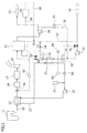
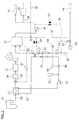
- the heat recovery and utilization system of the present embodiment includes a boiler 11 for electricity generation, a heat recovery unit 13 for recovery of heat from exhaust gas of this boiler, a dust collector unit 14 for removing smoke dust from exhaust gas after heat recovery, a desulfurization unit 15 for removing sulfur oxides from exhaust gas after removal of smoke dust, and a smokestack 17 for emitting exhaust gas into the atmosphere after desulfurization.
- An exhaust gas passage 12 in which boiler exhaust gas flows is provided in each section between the boiler 11, the heat recovery unit 13, the desulfurization unit 15, and the smokestack 17.
- this system includes a steam turbine which is operated by steam from the boiler 11 and a power generator for generating electricity with driving power from the steam turbine.
- it may also include a condenser for condensation of exhaust gas from a steam turbine by cooling and a heater for heating this condensate water and supplying it to the boiler 11.
- the heater also may include a first heater for heating with low-pressure extracted steam from the steam turbine and a second heater for heating with highpressure extracted steam from the steam turbine.
- the exhaust gas passage 12 may include an air preheater for preheating air supplied to the boiler 11 by using exhaust gas as a heat source between the boiler 11 and the heat recovery unit 13.
- the dust collector unit 14 may be provided between the boiler 11 (air preheater if the air preheater is provided) and the heat recovery unit 13, different from that shown in the figure.
- the heat recovery unit 13 contains a heat transfer pipe in which a heat medium flows within the passage of the boiler exhaust gas to recover heat from the boiler exhaust gas.
- this system includes a heat exchanger 21 for exchanging heat between the aforementioned heat medium and supply water for the local area heat supply facility, a heat medium circulation pipe 22 in which heat medium circulates between the heat exchanger 21 and the heat recovery unit 13, and a supply water pipe 32 in which the supply water for the local area heat supply facility flows so as to pass through the heat exchanger 21.
- the heat medium circulation pipe 22 is provided with a recirculation pump 23 for pressure-feeding heat medium and a heat medium tank 25 for supplying heat medium to this circulation pipe.
- the supply water pipe 33 contains a low temperature water pump 33 for pressure-feeding supply water (low temperature water 41) to the heat exchanger side, a heat accumulator 31 which stores supply water (high temperature water) heated by the heat exchanger 21 to accumulate heat, and a high temperature pump 34 for pressure-feeding high temperature water 43 from the heat accumulator 31 to a local area.
- the heat accumulator 31 has a high temperature water inlet which is supplied with the aforementioned high temperature water for heat accumulation and a low temperature water inlet which is supplied with supply water whose temperature is lower than a predetermined temperature.
- the low temperature water inlet of this heat accumulator 31 is connected to a low temperature water bypass pipe 37 which feeds supply water (low temperature water 41) to the heat accumulator 31 without heating with the heat exchanger 21.
- a startup drain pipe 35 which feeds supply water to the low temperature water bypass pipe 37 after passing the heat exchanger 21 is provided on the downstream side of the supply water pipe 32 with respect to the heat exchanger 21.
- a startup water supply pipe 36 which feeds high temperature water to the heat exchanger 21 is provided from the downstream side of the high temperature water pump 34 in the supply water pipe 32.
- a valve 51 which controls the amount of supply water (low temperature water) to the heat exchanger 21 is provided upstream of the low temperature water pump 33, a supply water amount adjusting valve 52 which controls the amount of the low temperature water 41 for the local area heat supply facility is provided between the low temperature water pump 33 and the heat exchanger 21, and a valve 53 which controls the amount of supply water to the high temperature water inlet of the heat accumulator 31 is provided between a connection point of the startup drain pipe 35 and the heat accumulator 31.
- the startup drain pipe 35 is provided with a valve 54 which controls supply of the supply water to the low temperature water inlet of the heat accumulator 31.
- the startup supply pipe 36 is provided with a valve 55 which controls supply of high temperature water from the heat exchanger 31 to the heat exchanger 21.
- the exhaust gas passage 12 is provided with an exhaust gas thermometer 56 for measuring temperature of exhaust gas between the heat recovery unit 13 and the desulfurization unit 15, and a remote monitoring control unit 57 which monitors and controls temperature of the exhaust gas thermometer.
- the heat medium circulation pipe 22 is provided with a heat medium thermometer 58 which measures temperature of heat medium and a remote monitoring control unit 59 which monitors and controls temperature of the heat medium thermometer downward of the heat exchanger 21.
- the supply water pipe 32 is provided with a supply water thermometer 60 for measuring temperature of supply water (high temperature water) and a remote monitoring control unit 61 which monitors and controls temperature of the supply water thermometer downward of the heat exchanger 21.
- This system is connected to these remote monitoring control units communicably and includes a central monitoring control unit 50 which controls the amount of supply water of the startup supply water valve 52.
- the valve 51 and the valve 53 are closed and then, the valve 54 and the valve 55 are opened so as to supply high temperature water having a temperature of 75 to 100°C for example, stored in the heat accumulator 31 to the heat exchanger 21 with the high temperature pump 34.
- the heat exchanger 21 is capable of heating it up to at least 70°C, preferably 70 to 90°C to warm up the heat recovery unit 13.
- boiler 11 is started and both a steam turbine (not shown) and a power generator (not shown) are driven with generated steam to generate power.
- exhaust gas having a very high temperature is discharged into the exhaust gas passage 12.
- boiler exhaust gas is introduced into the heat recovery unit 13 in such a condition that it has a temperature of 120 to 160°C, for example.
- the heat exchanger 13 exchanges heat with the heat medium heated up to a predetermined temperature and after the temperature of the heat medium is reduced to 80 to 110°C, the heat medium is introduced into the desulfurization unit 15. Then, the boiler exhaust gas after desulfurization is discharged into the atmosphere through the smokestack 17.
- the temperature of high temperature water used in heating the heat medium in the heat exchanger 21 decreases to 30 to 50°C, for example.
- this water is introduced to the low temperature inlet of the heat accumulator 31 via the startup drain pipe 35 and the low temperature bypass pipe 37.
- High temperature water is supplied to the heat exchanger 21 from the heat accumulator 31 so as to warm up the heat recovery unit 13 in the above-described manner and at the same time, the high temperature water 43 may be supplied for heating and the like in a local area as a local heat supply facility.
- the low temperature water 41 used for heating and the like is collected to the low temperature inlet of the heat accumulator 31 via the low temperature bypass pipe 37.
- this system is operated normally.
- the valve 51 and the valve 53 are opened, and then, the valve 54 and the valve 55 are closed so as to introduce part of the low temperature water 41 having a temperature of 30 to 50°C, for example, as supply water for local area heat supply facility, to the heat exchanger 21 with the low temperature water pump 33.
- the heat medium which is introduced to the heat exchanger 21 upon normal operation is heated up to 100 to 120°C, for example, with the boiler exhaust gas in the heat recovery unit 13s.
- the heat exchanger 21 is capable of heating the low temperature water 41 having such a high temperature up to 75 to 100°C, for example.
- the heated supply water is introduced to the high temperature inlet of the heat accumulator 31.
- the heated supply water is supplied to a local area as the high temperature water 43 for heating and the like from the heat accumulator 31 by means of the high temperature pump 34 via the supply water pipe 32.
- the heat medium which has heated the low temperature water 41 in the heat exchanger 21 decreases to 70 to 90°C, for example, it is reintroduced to the heat recovery unit 13 via the heat medium circulation pipe 22 and heated up to a predetermined temperature.
- fresh heat medium can be supplied to the heat medium circulation pipe 22 from the heat medium tank 25.
- the heat medium is not restricted to any particular one, it is preferable to use boiler supply water or pure water (deionized water) containing deoxidant.
- the temperature of the heat medium is measured and monitored by the heat medium thermometer 58 and the remote monitoring control unit 59, and the central monitoring control unit 50 controls the supply water amount adjusting valve 52 so as to control the amount of the low temperature water 41 supplied to the heat exchanger 21. That is, if a temperature measured by the heat medium thermometer 58 is lower than the predetermined temperature, a flow rate of the low temperature water 41 is decreased with the supply water amount adjusting valve 52 to decrease the heat exchange amount in the heat exchanger 21, thereby keeping the temperature of the heat medium at a predetermined temperature.
- This supply water adjusting valve 52 is usable even upon startup operation.
- the flow rate of the high temperature water supplied to the heat exchanger 21 can be controlled with the supply water adjusting valve 52.
- the high temperature water stored in the heat accumulator 31 is efficiently usable.
- the temperature of boiler exhaust gas downward of the heat recovery unit 13 in the exhaust gas passage 12 is kept at 80°C or more, for example.
- the temperature of exhaust gas downward of the heat recovery unit 13 is measured and monitored by the exhaust gas thermometer 56 and the remote monitoring control unit 57 located there. If a temperature measured by the exhaust gas thermometer 56 is lower than the predetermined temperature, the supply water amount adjusting valve 52 is controlled by the central monitoring control unit 50 so as to decrease the flow rate of the low temperature water 41 supplied to the heat exchanger 21. Consequently, the heat exchange amount in the heat exchanger 21 is decreased, thereby keeping the temperature of the boiler exhaust gas at a predetermined temperature.
- temperature control of the boiler exhaust gas downward of the heat recovery unit 13 is performed by flow rate control of the low temperature water 41 in the heat exchanger 21.
- no bypass pipe for the heat medium or control valve for the bypass flow rate provided conventionally within the heat medium circulation pipe, is required.
- a dryer 45 may be provided downward of the high temperature pump 34 in the supply water pipe 32.
- the dryer 45 is an apparatus which dries biomass such as thinnings, chips, chaff, pulp, raw garbage, and sludge.
- the dryer 45 is provided with a dryer drain pipe 38 which brings back supply water discharged from the dryer 45 to the low temperature inlet of the heat accumulator 31 and a valve 39 which controls supply of the high temperature water to the dryer 45.
- Heat balance was simulated using a system illustrated in Figs. 1 and 2 .
- the temperature of boiler exhaust gas when it was introduced into the heat recovery unit 13 was set to 130°C
- the temperature of heat medium in the heat medium circulation pipe 22 was initially set to 35°C
- the temperature of the low temperature water 41 for a local area heat supply facility was set to 40°C
- the temperature of high temperature water stored in the heat accumulator 31 was initially set to 85°C.
- the flow rate of the boiler exhaust gas was set to 1,200,000 Nm 3 /h
- the flow rate of heat medium in the heat medium circulation pipe 22 was set to 510 m 3 /h
- the volume of high temperature water stored in the heat accumulator 31 was set to 100 m 3 .
Landscapes
- Engineering & Computer Science (AREA)
- Mechanical Engineering (AREA)
- General Engineering & Computer Science (AREA)
- Chemical & Material Sciences (AREA)
- Combustion & Propulsion (AREA)
- Physics & Mathematics (AREA)
- Thermal Sciences (AREA)
- Air Supply (AREA)
- Heat-Pump Type And Storage Water Heaters (AREA)
- Engine Equipment That Uses Special Cycles (AREA)
- Chimneys And Flues (AREA)
Abstract
Description
- The present invention relates to a heat recovery and utilization system for recovery of heat from boiler exhaust gas from a power plant.
- Japanese Patent Application Publication No.
2001-239129 2006-308269 2001-239129 2006-308269 -
- Patent Literature 1: Japanese Patent Application Publication No.
2001-239129 - Patent Literature 2: Japanese Patent Application Publication No.
2006-308269 - As a utilization method of heat recovered from boiler exhaust gas with the heat recovery unit, as described above, a method of heating boiler supply water or preheating air has been known and although this has improved thermal efficiency of an entire power plant, further improvement of thermal efficiency has been demanded.
- When a heat recovery unit is provided as described above, it is necessary to warm up the heat recovery unit at the time of startup of boiler exhaust gas treatment line. The warm-up requires utilization of steam from a different boiler from a boiler of the treatment line and additional equipment such as a heat exchanger, a drain collector, and therefore accompanies a problem that construction cost and operation cost are incurred. In addition, after the treatment line is stopped, application destination of the heat recovered from the boiler exhaust gas disappears, so that efficient utilization of the recovered heat is disabled.
- Accordingly, in view of the above-stated problems, an object of the present invention is to provide a heat recovery and utilization system capable of efficient utilization of heat recovered from boiler exhaust gas with a heat recovery unit without any complicated equipment or high operation cost.
- To achieve the above-described object, the present invention provides a heat recovery and utilization system including: a boiler for electricity generation; a heat recovery unit for recovering heat from exhaust gas of the boiler; a heat exchanger for using heat recovered with the heat recovery unit as a heat source for equipment other than equipment for electricity generation; and a heat accumulator for accumulating a heat source for the equipment other than for electricity generation, wherein the heat exchanger preheats the heat recovery unit with the heat accumulated in the heat accumulator.
- Preferably, the equipment other than for electricity generation is a local area heat supply facility and in this case, supply water to the local area heat supply facility is heated with heat recovered by the heat recovery unit. Preferably, the equipment other than for electricity generation is biomass drying equipment and heat medium in the biomass drying equipment is heated with heat recovered by the heat recovery unit. The equipment other than for electricity generation may be provided together with both the local area heat supply facility and the biomass drying equipment.
- Preferably, the heat recovery and utilization system of the present invention includes a heat medium circulation line in which heat medium circulates between the heat recovery unit and the heat exchanger to exchange the heat recovered by the heat recovery unit with the heat exchanger. Preferably, the heat recovery and utilization system of the present invention further includes a control unit for controlling an amount of heat recovered by the heat recovery unit, which is used as heat source for the equipment other than for electricity generation, based on temperature of boiler exhaust gas after heat recovery by the heat recovery unit.
- According to the present invention, by providing the heat exchanger which uses heat recovered by the heat recovery unit for heat source for other equipment than for electricity generation, for example, a heat source for supply water to a local area heat supply facility or heat source for biomass drying equipment, the heat recovered by the heat recovery unit can be used efficiently without any limitation of a conventional power plant equipment. A heat accumulator which accumulates a heat source for equipment other than for electricity generation is used and the heat exchanger preheats the heat recovery unit using the heat source accumulated in the heat accumulator. As a result, the heat recovery unit can be preheated without using steam as conventionally, and furthermore, it is not necessary to provide such equipment as the heat exchanger and the drain collector for preheating the heat recovery unit with steam. Accordingly, the present invention provides a heat recovery and utilization system capable of efficiently utilizing heat recovered by the heat recovery unit from boiler exhaust gas without any complicated equipment or high operation cost.
-
- [
Fig. 1] Fig. 1 is a schematic view illustrating an embodiment of a heat recovery and utilization system of the present invention for describing an operation thereof at the time of startup. - [
Fig. 2] Fig. 2 is a schematic view illustrating an embodiment of a heat recovery and utilization system of the present invention for describing an operation thereof at the time of ordinary operation. - Hereinafter, an embodiment of the heat recovery and utilization system of the present invention will be described with reference to the accompanying drawings. The present invention is not limited to this embodiment.
- As shown in
Fig. 1 , the heat recovery and utilization system of the present embodiment includes aboiler 11 for electricity generation, aheat recovery unit 13 for recovery of heat from exhaust gas of this boiler, adust collector unit 14 for removing smoke dust from exhaust gas after heat recovery, adesulfurization unit 15 for removing sulfur oxides from exhaust gas after removal of smoke dust, and asmokestack 17 for emitting exhaust gas into the atmosphere after desulfurization. Anexhaust gas passage 12 in which boiler exhaust gas flows is provided in each section between theboiler 11, theheat recovery unit 13, thedesulfurization unit 15, and thesmokestack 17. - Although not shown, this system includes a steam turbine which is operated by steam from the
boiler 11 and a power generator for generating electricity with driving power from the steam turbine. In addition, it may also include a condenser for condensation of exhaust gas from a steam turbine by cooling and a heater for heating this condensate water and supplying it to theboiler 11. The heater also may include a first heater for heating with low-pressure extracted steam from the steam turbine and a second heater for heating with highpressure extracted steam from the steam turbine. - Although not shown, the
exhaust gas passage 12 may include an air preheater for preheating air supplied to theboiler 11 by using exhaust gas as a heat source between theboiler 11 and theheat recovery unit 13. Thedust collector unit 14 may be provided between the boiler 11 (air preheater if the air preheater is provided) and theheat recovery unit 13, different from that shown in the figure. - The
heat recovery unit 13 contains a heat transfer pipe in which a heat medium flows within the passage of the boiler exhaust gas to recover heat from the boiler exhaust gas. To utilize recovered heat as a heat source for a local area heat supply facility, this system includes aheat exchanger 21 for exchanging heat between the aforementioned heat medium and supply water for the local area heat supply facility, a heat medium circulation pipe 22 in which heat medium circulates between theheat exchanger 21 and theheat recovery unit 13, and asupply water pipe 32 in which the supply water for the local area heat supply facility flows so as to pass through theheat exchanger 21. - The heat medium circulation pipe 22 is provided with a
recirculation pump 23 for pressure-feeding heat medium and aheat medium tank 25 for supplying heat medium to this circulation pipe. Thesupply water pipe 33 contains a lowtemperature water pump 33 for pressure-feeding supply water (low temperature water 41) to the heat exchanger side, aheat accumulator 31 which stores supply water (high temperature water) heated by theheat exchanger 21 to accumulate heat, and ahigh temperature pump 34 for pressure-feedinghigh temperature water 43 from theheat accumulator 31 to a local area. - The
heat accumulator 31 has a high temperature water inlet which is supplied with the aforementioned high temperature water for heat accumulation and a low temperature water inlet which is supplied with supply water whose temperature is lower than a predetermined temperature. The low temperature water inlet of thisheat accumulator 31 is connected to a low temperaturewater bypass pipe 37 which feeds supply water (low temperature water 41) to theheat accumulator 31 without heating with theheat exchanger 21. Then, astartup drain pipe 35 which feeds supply water to the low temperaturewater bypass pipe 37 after passing theheat exchanger 21 is provided on the downstream side of thesupply water pipe 32 with respect to theheat exchanger 21. Additionally, a startupwater supply pipe 36 which feeds high temperature water to theheat exchanger 21 is provided from the downstream side of the hightemperature water pump 34 in thesupply water pipe 32. - In the
supply water pipe 32, avalve 51 which controls the amount of supply water (low temperature water) to theheat exchanger 21 is provided upstream of the lowtemperature water pump 33, a supply wateramount adjusting valve 52 which controls the amount of thelow temperature water 41 for the local area heat supply facility is provided between the lowtemperature water pump 33 and theheat exchanger 21, and avalve 53 which controls the amount of supply water to the high temperature water inlet of theheat accumulator 31 is provided between a connection point of thestartup drain pipe 35 and theheat accumulator 31. Thestartup drain pipe 35 is provided with avalve 54 which controls supply of the supply water to the low temperature water inlet of theheat accumulator 31. Thestartup supply pipe 36 is provided with avalve 55 which controls supply of high temperature water from theheat exchanger 31 to theheat exchanger 21. - The
exhaust gas passage 12 is provided with anexhaust gas thermometer 56 for measuring temperature of exhaust gas between theheat recovery unit 13 and thedesulfurization unit 15, and a remotemonitoring control unit 57 which monitors and controls temperature of the exhaust gas thermometer. The heat medium circulation pipe 22 is provided with aheat medium thermometer 58 which measures temperature of heat medium and a remotemonitoring control unit 59 which monitors and controls temperature of the heat medium thermometer downward of theheat exchanger 21. Thesupply water pipe 32 is provided with asupply water thermometer 60 for measuring temperature of supply water (high temperature water) and a remotemonitoring control unit 61 which monitors and controls temperature of the supply water thermometer downward of theheat exchanger 21. This system is connected to these remote monitoring control units communicably and includes a centralmonitoring control unit 50 which controls the amount of supply water of the startupsupply water valve 52. - With such a configuration, at the time of startup of this system, first, as shown in
Fig. 1 , thevalve 51 and thevalve 53 are closed and then, thevalve 54 and thevalve 55 are opened so as to supply high temperature water having a temperature of 75 to 100°C for example, stored in theheat accumulator 31 to theheat exchanger 21 with thehigh temperature pump 34. As a result, although heat medium contained in the heat medium circulation pipe 22 before startup has as low a temperature as 20 to 40°C, for example, theheat exchanger 21 is capable of heating it up to at least 70°C, preferably 70 to 90°C to warm up theheat recovery unit 13. - Next, the
boiler 11 is started and both a steam turbine (not shown) and a power generator (not shown) are driven with generated steam to generate power. At the same time, exhaust gas having a very high temperature is discharged into theexhaust gas passage 12. After passing through an air preheater (not shown) as required, boiler exhaust gas is introduced into theheat recovery unit 13 in such a condition that it has a temperature of 120 to 160°C, for example. Theheat exchanger 13 exchanges heat with the heat medium heated up to a predetermined temperature and after the temperature of the heat medium is reduced to 80 to 110°C, the heat medium is introduced into thedesulfurization unit 15. Then, the boiler exhaust gas after desulfurization is discharged into the atmosphere through thesmokestack 17. - If the exhaust gas temperature decreases too extremely in the
heat recovery unit 13 before it is introduced into thedesulfurization unit 15, corrosive constituents (e.g., sulfur compounds such as sulfuric acid) in the exhaust gas reaches a dew point, and thereby a problem in that apparatuses and devices disposed downward of theheat recovery unit 13 corrode may occur. Thus, by heating the heat medium in theheat exchanger 21 preliminarily to warm up theheat recovery unit 13 up to a predetermined temperature, the temperature of boiler exhaust gas can be kept at the predetermined temperature. Although conventionally steam has been produced in a power plant so as to warm up theheat recovery unit 13, the present embodiment requires no steam and further no apparatus or device such as a heat exchanger, a drain collecting unit for warming heat medium in theheat recovery unit 13 with this steam is also unnecessary. - On the other hand, the temperature of high temperature water used in heating the heat medium in the
heat exchanger 21 decreases to 30 to 50°C, for example. Thus, this water is introduced to the low temperature inlet of theheat accumulator 31 via thestartup drain pipe 35 and the lowtemperature bypass pipe 37. High temperature water is supplied to theheat exchanger 21 from theheat accumulator 31 so as to warm up theheat recovery unit 13 in the above-described manner and at the same time, thehigh temperature water 43 may be supplied for heating and the like in a local area as a local heat supply facility. Thelow temperature water 41 used for heating and the like is collected to the low temperature inlet of theheat accumulator 31 via the lowtemperature bypass pipe 37. - After the warm-up of the
heat recovery unit 13 is completed, this system is operated normally. As shown inFig. 2 , thevalve 51 and thevalve 53 are opened, and then, thevalve 54 and thevalve 55 are closed so as to introduce part of thelow temperature water 41 having a temperature of 30 to 50°C, for example, as supply water for local area heat supply facility, to theheat exchanger 21 with the lowtemperature water pump 33. The heat medium which is introduced to theheat exchanger 21 upon normal operation is heated up to 100 to 120°C, for example, with the boiler exhaust gas in the heat recovery unit 13s. Thus, theheat exchanger 21 is capable of heating thelow temperature water 41 having such a high temperature up to 75 to 100°C, for example. The heated supply water is introduced to the high temperature inlet of theheat accumulator 31. - The heated supply water is supplied to a local area as the
high temperature water 43 for heating and the like from theheat accumulator 31 by means of thehigh temperature pump 34 via thesupply water pipe 32. Although the heat medium which has heated thelow temperature water 41 in theheat exchanger 21 decreases to 70 to 90°C, for example, it is reintroduced to theheat recovery unit 13 via the heat medium circulation pipe 22 and heated up to a predetermined temperature. - Because the heat medium is reduced or deteriorated due to cyclic use, fresh heat medium can be supplied to the heat medium circulation pipe 22 from the
heat medium tank 25. Although the heat medium is not restricted to any particular one, it is preferable to use boiler supply water or pure water (deionized water) containing deoxidant. - Upon normal operation also, it is preferable to keep the temperature of the heat medium downward of the
heat exchanger 21 in the heat medium calculation pipe 22 at 70° or more, for example. Thus, the temperature of the heat medium is measured and monitored by theheat medium thermometer 58 and the remotemonitoring control unit 59, and the centralmonitoring control unit 50 controls the supply wateramount adjusting valve 52 so as to control the amount of thelow temperature water 41 supplied to theheat exchanger 21. That is, if a temperature measured by theheat medium thermometer 58 is lower than the predetermined temperature, a flow rate of thelow temperature water 41 is decreased with the supply wateramount adjusting valve 52 to decrease the heat exchange amount in theheat exchanger 21, thereby keeping the temperature of the heat medium at a predetermined temperature. - This supply
water adjusting valve 52 is usable even upon startup operation. In correspondence with an increase in the temperature of the heat medium measured by theheat medium thermometer 58 from a low temperature up to a predetermined temperature, the flow rate of the high temperature water supplied to theheat exchanger 21 can be controlled with the supplywater adjusting valve 52. As a result, the high temperature water stored in theheat accumulator 31 is efficiently usable. - In addition, preferably, the temperature of boiler exhaust gas downward of the
heat recovery unit 13 in theexhaust gas passage 12 is kept at 80°C or more, for example. Thus, the temperature of exhaust gas downward of theheat recovery unit 13 is measured and monitored by theexhaust gas thermometer 56 and the remotemonitoring control unit 57 located there. If a temperature measured by theexhaust gas thermometer 56 is lower than the predetermined temperature, the supply wateramount adjusting valve 52 is controlled by the centralmonitoring control unit 50 so as to decrease the flow rate of thelow temperature water 41 supplied to theheat exchanger 21. Consequently, the heat exchange amount in theheat exchanger 21 is decreased, thereby keeping the temperature of the boiler exhaust gas at a predetermined temperature. - In the present embodiment, temperature control of the boiler exhaust gas downward of the
heat recovery unit 13 is performed by flow rate control of thelow temperature water 41 in theheat exchanger 21. Thus, no bypass pipe for the heat medium or control valve for the bypass flow rate, provided conventionally within the heat medium circulation pipe, is required. - According to the present invention, as shown in
Figs. 1 and2 , as well as the above-described local area heat supply facility, adryer 45 may be provided downward of thehigh temperature pump 34 in thesupply water pipe 32. Thedryer 45 is an apparatus which dries biomass such as thinnings, chips, chaff, pulp, raw garbage, and sludge. Thedryer 45 is provided with adryer drain pipe 38 which brings back supply water discharged from thedryer 45 to the low temperature inlet of theheat accumulator 31 and avalve 39 which controls supply of the high temperature water to thedryer 45. - With this configuration, high temperature water having a predetermined temperature is supplied to the
dryer 45 as well as local area, where it can be used as a heat source for drying biomass generated there. Although the drawings show a case in which both the local area heat supply facility and the dryer are provided, the present invention may be applied to a case in which only the dryer is provided. - Heat balance was simulated using a system illustrated in
Figs. 1 and2 . The temperature of boiler exhaust gas when it was introduced into theheat recovery unit 13 was set to 130°C, the temperature of heat medium in the heat medium circulation pipe 22 was initially set to 35°C, the temperature of thelow temperature water 41 for a local area heat supply facility was set to 40°C, and the temperature of high temperature water stored in theheat accumulator 31 was initially set to 85°C. Then, the flow rate of the boiler exhaust gas was set to 1,200,000 Nm3/h, the flow rate of heat medium in the heat medium circulation pipe 22 was set to 510 m3/h, and the volume of high temperature water stored in theheat accumulator 31 was set to 100 m3. - Upon startup of the system, high temperature water from the
heat accumulator 31 was used. As a result, heat medium having a temperature of 70°C could be supplied to theheat recovery unit 13. Next, the system was changed to normal operation. To keep the temperature of boiler exhaust gas downward of theheat recovery unit 13 at 85°C, heat medium having a temperature of 75°C was supplied to theheat recovery unit 13. As a result, the heat medium was heated to 110°C by way of heat exchange with boiler exhaust gas. By introducing heat medium having a temperature of 110°C to theheat exchanger 21, low temperature water whose flow rate was 400 m3/h and having a temperature of 40°C could be heated up to 85°C which was sufficient as the high temperature water for a local area heat supply facility. -
- 11:
- boiler
- 13:
- heat recovery unit
- 14:
- dust collector
- 15:
- desulfurization unit
- 17:
- smokestack
- 21:
- heat exchanger
- 22:
- heat medium circulation pipe
- 23:
- recirculation pump
- 25:
- heat medium tank
- 31:
- heat accumulator
- 32:
- supply water pipe
- 33:
- low temperature pump
- 34:
- high temperature pump
- 35:
- startup drain pipe
- 36:
- startup supply pipe
- 37:
- low temperature water bypass pipe
- 38:
- dryer drain pipe
- 39:
- valve
- 41:
- low temperature water
- 43:
- high temperature water
- 45:
- dryer
- 50:
- central monitoring control unit
- 51, 53, 54, 55:
- valve
- 52:
- supply water adjusting valve
- 56:
- exhaust gas thermometer
- 57, 59, 61:
- remote monitoring control unit
- 58:
- heat medium thermometer
- 60:
- supply water thermometer
Claims (5)
- A heat recovery and utilization system comprising:a boiler for electricity generation;a heat recovery unit for recovering heat from exhaust gas of the boiler;a heat exchanger for using heat recovered with the heat recovery unit as heat source for equipment other than equipment for electricity generation; anda heat accumulator for accumulating heat source of the equipment other than equipment for electricity generation,wherein the heat exchanger preheats the heat recovery unit with the heat source accumulated in the heat accumulator.
- The heat recovery and utilization system according to claim 1, wherein the equipment other than for electricity generation is local area heat supply facility and supply water to the local area heat supply facility is heated with heat recovered by the heat recovery unit.
- The heat recovery and utilization system according to claim 1, wherein the equipment other than for electricity generation is biomass drying equipment and heat medium in the biomass drying equipment is heated with heat recovered by the heat recovery unit.
- The heat recovery and utilization system according to any one of claims 1 to 3 further comprising a heat medium circulation line in which heat medium circulates between the heat recovery unit and the heat exchanger to exchange heat recovered by the heat recovery unit with the heat exchanger.
- The heat recovery and utilization system according to any one of claims 1 to 4 further comprising a control unit for controlling a heat exchange amount with heat recovered by the heat recovery unit as heat source for the equipment other than for electricity generation based on temperature of boiler exhaust gas after heat recovery by the heat recovery unit.
Priority Applications (2)
| Application Number | Priority Date | Filing Date | Title |
|---|---|---|---|
| RSP20190974 RS59189B1 (en) | 2010-12-27 | 2011-03-04 | Heat recovery and utilization system |
| PL11853289T PL2660516T3 (en) | 2010-12-27 | 2011-03-04 | Heat recovery and utilization system |
Applications Claiming Priority (2)
| Application Number | Priority Date | Filing Date | Title |
|---|---|---|---|
| JP2010290057A JP5636955B2 (en) | 2010-12-27 | 2010-12-27 | Heat recovery system |
| PCT/JP2011/055020 WO2012090517A1 (en) | 2010-12-27 | 2011-03-04 | Heat recovery and utilization system |
Publications (3)
| Publication Number | Publication Date |
|---|---|
| EP2660516A1 true EP2660516A1 (en) | 2013-11-06 |
| EP2660516A4 EP2660516A4 (en) | 2017-03-29 |
| EP2660516B1 EP2660516B1 (en) | 2019-06-19 |
Family
ID=46382644
Family Applications (1)
| Application Number | Title | Priority Date | Filing Date |
|---|---|---|---|
| EP11853289.4A Active EP2660516B1 (en) | 2010-12-27 | 2011-03-04 | Heat recovery and utilization system |
Country Status (9)
| Country | Link |
|---|---|
| US (1) | US9803853B2 (en) |
| EP (1) | EP2660516B1 (en) |
| JP (1) | JP5636955B2 (en) |
| KR (1) | KR101473601B1 (en) |
| CN (1) | CN103249999B (en) |
| ES (1) | ES2732296T3 (en) |
| PL (1) | PL2660516T3 (en) |
| RS (1) | RS59189B1 (en) |
| WO (1) | WO2012090517A1 (en) |
Families Citing this family (10)
| Publication number | Priority date | Publication date | Assignee | Title |
|---|---|---|---|---|
| JP5461666B1 (en) * | 2012-11-15 | 2014-04-02 | 三井造船株式会社 | Thermal storage power generation apparatus and control method thereof |
| JP6214253B2 (en) * | 2013-07-12 | 2017-10-18 | 日立造船株式会社 | Boiler system |
| CN103742891A (en) * | 2014-01-09 | 2014-04-23 | 程礼华 | Multi-unit combined power generation process and multi-unit combined power generation device |
| CN204372959U (en) * | 2014-03-27 | 2015-06-03 | 黑龙江国德节能服务有限公司 | Gas fired-boiler smoke gas treatment system |
| US10378763B2 (en) | 2015-12-03 | 2019-08-13 | General Electric Company | Method and apparatus to facilitate heating feedwater in a power generation system |
| CN107975393A (en) * | 2017-12-18 | 2018-05-01 | 湖北松源矸石发电有限公司 | A kind of thermal power generation system that there is fume afterheat and utilize |
| CN109869786B (en) * | 2019-02-02 | 2023-07-18 | 华电电力科学研究院有限公司 | Steam extraction and heat supply integrated system for power peak regulation of combined cycle unit and operation method of steam extraction and heat supply integrated system |
| JP7367040B2 (en) * | 2019-09-18 | 2023-10-23 | 株式会社日立産機システム | heat recovery equipment |
| US12455098B2 (en) | 2022-04-12 | 2025-10-28 | The Cleaver-Brooks Company, Inc. | Thermal efficiency system and method for boiler plant |
| CN115371114B (en) * | 2022-07-08 | 2025-08-12 | 国家能源集团科学技术研究院有限公司 | Condensate water waste heat utilization system of gas-steam combined cycle cogeneration unit |
Family Cites Families (19)
| Publication number | Priority date | Publication date | Assignee | Title |
|---|---|---|---|---|
| CH552771A (en) * | 1972-06-12 | 1974-08-15 | Sulzer Ag | FORCED FLOW STEAM GENERATOR. |
| US3974642A (en) * | 1973-01-26 | 1976-08-17 | Fives-Cail Babcock Societe Anonyme | Hybrid cycle power plant with heat accumulator for storing heat exchange fluid transferring heat between cycles |
| US3863708A (en) * | 1974-01-07 | 1975-02-04 | Amax Inc | Modulatable heat exchanger with restraint to avoid condensation |
| US4094148A (en) | 1977-03-14 | 1978-06-13 | Stone & Webster Engineering Corporation | Thermal storage with molten salt for peaking power |
| JPH0823290B2 (en) * | 1987-04-14 | 1996-03-06 | ヤンマーディーゼル株式会社 | Exhaust temperature control device for internal combustion engine |
| GB9319365D0 (en) | 1993-09-18 | 1993-11-03 | Vert Investments Ltd | Vitrification & power generation system |
| JP3063622B2 (en) * | 1996-05-28 | 2000-07-12 | 株式会社日立製作所 | Waste power generation system and waste treatment system |
| JP4725985B2 (en) | 2000-03-03 | 2011-07-13 | バブコック日立株式会社 | Operation method of flue gas treatment equipment |
| JP3977606B2 (en) * | 2001-04-17 | 2007-09-19 | 東京瓦斯株式会社 | Waste heat recovery control method and apparatus |
| US7972582B2 (en) * | 2001-12-04 | 2011-07-05 | Ebara Corporation | Method and apparatus for treating exhaust gas |
| CA2498263C (en) * | 2002-09-09 | 2011-05-03 | Babcock-Hitachi Kabushiki Kaisha | Exhaust smoke-processing system |
| JP2005036747A (en) * | 2003-07-17 | 2005-02-10 | Ishikawajima Harima Heavy Ind Co Ltd | Engine warm-up method and warm-up device |
| FI121637B (en) | 2004-07-23 | 2011-02-15 | Foster Wheeler Energia Oy | Method and apparatus for protecting a heat exchanger |
| JP4959156B2 (en) | 2004-11-29 | 2012-06-20 | 三菱重工業株式会社 | Heat recovery equipment |
| PL1816397T3 (en) * | 2006-02-02 | 2015-08-31 | Fritz Egger Gmbh & Co Og | Method and device for heat recovery, from humid exhaust air |
| EA016107B1 (en) * | 2007-02-20 | 2012-02-28 | Магальди Ричерке Э Бреветти С.Р.Л. | Plant and method for dry extracting / cooling heavy ashes and for controlling the combustion of high unburnt content residues |
| US9121606B2 (en) * | 2008-02-19 | 2015-09-01 | Srivats Srinivasachar | Method of manufacturing carbon-rich product and co-products |
| JP2010151432A (en) * | 2008-12-26 | 2010-07-08 | Kobelco Eco-Solutions Co Ltd | Incineration exhaust heat utilization system for utilizing exhaust heat of waste incinerator |
| CN101813431B (en) | 2010-03-24 | 2011-11-02 | 浙江西子联合工程有限公司 | Temperature-control variable-pressure heat accumulator control system and control method thereof |
-
2010
- 2010-12-27 JP JP2010290057A patent/JP5636955B2/en not_active Expired - Fee Related
-
2011
- 2011-03-04 ES ES11853289T patent/ES2732296T3/en active Active
- 2011-03-04 CN CN201180058447.9A patent/CN103249999B/en not_active Expired - Fee Related
- 2011-03-04 RS RSP20190974 patent/RS59189B1/en unknown
- 2011-03-04 PL PL11853289T patent/PL2660516T3/en unknown
- 2011-03-04 WO PCT/JP2011/055020 patent/WO2012090517A1/en not_active Ceased
- 2011-03-04 KR KR1020137016130A patent/KR101473601B1/en not_active Expired - Fee Related
- 2011-03-04 US US13/989,680 patent/US9803853B2/en not_active Expired - Fee Related
- 2011-03-04 EP EP11853289.4A patent/EP2660516B1/en active Active
Also Published As
| Publication number | Publication date |
|---|---|
| CN103249999A (en) | 2013-08-14 |
| WO2012090517A1 (en) | 2012-07-05 |
| RS59189B1 (en) | 2019-10-31 |
| PL2660516T3 (en) | 2019-09-30 |
| KR20130087049A (en) | 2013-08-05 |
| JP5636955B2 (en) | 2014-12-10 |
| KR101473601B1 (en) | 2014-12-16 |
| EP2660516A4 (en) | 2017-03-29 |
| US9803853B2 (en) | 2017-10-31 |
| JP2012137247A (en) | 2012-07-19 |
| ES2732296T3 (en) | 2019-11-21 |
| US20130247845A1 (en) | 2013-09-26 |
| CN103249999B (en) | 2015-08-05 |
| EP2660516B1 (en) | 2019-06-19 |
Similar Documents
| Publication | Publication Date | Title |
|---|---|---|
| EP2660516B1 (en) | Heat recovery and utilization system | |
| US9453432B2 (en) | Power generation system | |
| EP2481895B1 (en) | Thermal power plant with carbon dioxide capture scrubbing equipment | |
| EP2375012B1 (en) | Boiler apparatus | |
| RU2688078C2 (en) | Coaling welded electric installation with oxy-ignition with heat integrating | |
| CN108443906B (en) | Flue gas waste heat utilization system and method based on multi-energy level and recirculated heating cold air | |
| JP2014009877A (en) | Flue gas treatment equipment and method | |
| KR101674705B1 (en) | Method for generating power from exhaust heat and system for generating power from exhaust heat | |
| US10147989B2 (en) | System for generating power from fuel cell waste heat | |
| JP2014009624A (en) | Waste heat utilization method, waste heat utilization system and treatment method of boiler exhaust gas | |
| EP2640936B1 (en) | Combined cycle plant for energy production and method for operating said plant | |
| CN210532424U (en) | Low-temperature waste heat utilization system | |
| JP4486391B2 (en) | Equipment for effective use of surplus steam | |
| WO2012137010A2 (en) | Biomass plant | |
| JP2007085294A (en) | Steam turbine plant and its operating method | |
| CN210688281U (en) | Flue gas treatment system | |
| CN116857823A (en) | System for recovering flue gas hydrothermal resources after desulfurization by combining flash evaporation with second-class heat pump | |
| CN104093944B (en) | For the combined cycle equipment of generating and for the method operating described equipment | |
| JP2014009835A (en) | Exhaust gas treatment apparatus | |
| JP2015075299A (en) | Waste treatment facility | |
| SE534557C2 (en) | Method of operation of a heating and power plant and heating and power plant | |
| JP5918810B2 (en) | Waste treatment facility and heat retention method for dust collector | |
| EP3394402B1 (en) | Condensing heat recovery steam generator | |
| NZ260810A (en) | Method for controlling geothermal power plant brine and steam flow through control valve based on predetermined parameter maximum quantities | |
| CN117308166A (en) | An integrated waste heat recovery heating system |
Legal Events
| Date | Code | Title | Description |
|---|---|---|---|
| PUAI | Public reference made under article 153(3) epc to a published international application that has entered the european phase |
Free format text: ORIGINAL CODE: 0009012 |
|
| 17P | Request for examination filed |
Effective date: 20130626 |
|
| AK | Designated contracting states |
Kind code of ref document: A1 Designated state(s): AL AT BE BG CH CY CZ DE DK EE ES FI FR GB GR HR HU IE IS IT LI LT LU LV MC MK MT NL NO PL PT RO RS SE SI SK SM TR |
|
| DAX | Request for extension of the european patent (deleted) | ||
| RAP1 | Party data changed (applicant data changed or rights of an application transferred) |
Owner name: MITSUBISHI HITACHI POWER SYSTEMS, LTD. |
|
| RA4 | Supplementary search report drawn up and despatched (corrected) |
Effective date: 20170301 |
|
| RIC1 | Information provided on ipc code assigned before grant |
Ipc: F23G 5/46 20060101ALI20170223BHEP Ipc: F23J 15/08 20060101ALI20170223BHEP Ipc: F02G 5/04 20060101ALI20170223BHEP Ipc: F23J 15/06 20060101AFI20170223BHEP Ipc: F01P 3/20 20060101ALI20170223BHEP Ipc: F01P 7/16 20060101ALI20170223BHEP |
|
| STAA | Information on the status of an ep patent application or granted ep patent |
Free format text: STATUS: EXAMINATION IS IN PROGRESS |
|
| 17Q | First examination report despatched |
Effective date: 20180531 |
|
| GRAP | Despatch of communication of intention to grant a patent |
Free format text: ORIGINAL CODE: EPIDOSNIGR1 |
|
| STAA | Information on the status of an ep patent application or granted ep patent |
Free format text: STATUS: GRANT OF PATENT IS INTENDED |
|
| INTG | Intention to grant announced |
Effective date: 20190109 |
|
| GRAS | Grant fee paid |
Free format text: ORIGINAL CODE: EPIDOSNIGR3 |
|
| GRAA | (expected) grant |
Free format text: ORIGINAL CODE: 0009210 |
|
| STAA | Information on the status of an ep patent application or granted ep patent |
Free format text: STATUS: THE PATENT HAS BEEN GRANTED |
|
| AK | Designated contracting states |
Kind code of ref document: B1 Designated state(s): AL AT BE BG CH CY CZ DE DK EE ES FI FR GB GR HR HU IE IS IT LI LT LU LV MC MK MT NL NO PL PT RO RS SE SI SK SM TR |
|
| REG | Reference to a national code |
Ref country code: GB Ref legal event code: FG4D |
|
| REG | Reference to a national code |
Ref country code: CH Ref legal event code: EP |
|
| REG | Reference to a national code |
Ref country code: IE Ref legal event code: FG4D |
|
| REG | Reference to a national code |
Ref country code: DE Ref legal event code: R096 Ref document number: 602011059926 Country of ref document: DE |
|
| REG | Reference to a national code |
Ref country code: AT Ref legal event code: REF Ref document number: 1146008 Country of ref document: AT Kind code of ref document: T Effective date: 20190715 |
|
| REG | Reference to a national code |
Ref country code: NL Ref legal event code: MP Effective date: 20190619 |
|
| PG25 | Lapsed in a contracting state [announced via postgrant information from national office to epo] |
Ref country code: AL Free format text: LAPSE BECAUSE OF FAILURE TO SUBMIT A TRANSLATION OF THE DESCRIPTION OR TO PAY THE FEE WITHIN THE PRESCRIBED TIME-LIMIT Effective date: 20190619 Ref country code: LT Free format text: LAPSE BECAUSE OF FAILURE TO SUBMIT A TRANSLATION OF THE DESCRIPTION OR TO PAY THE FEE WITHIN THE PRESCRIBED TIME-LIMIT Effective date: 20190619 Ref country code: HR Free format text: LAPSE BECAUSE OF FAILURE TO SUBMIT A TRANSLATION OF THE DESCRIPTION OR TO PAY THE FEE WITHIN THE PRESCRIBED TIME-LIMIT Effective date: 20190619 Ref country code: NO Free format text: LAPSE BECAUSE OF FAILURE TO SUBMIT A TRANSLATION OF THE DESCRIPTION OR TO PAY THE FEE WITHIN THE PRESCRIBED TIME-LIMIT Effective date: 20190919 Ref country code: SE Free format text: LAPSE BECAUSE OF FAILURE TO SUBMIT A TRANSLATION OF THE DESCRIPTION OR TO PAY THE FEE WITHIN THE PRESCRIBED TIME-LIMIT Effective date: 20190619 Ref country code: FI Free format text: LAPSE BECAUSE OF FAILURE TO SUBMIT A TRANSLATION OF THE DESCRIPTION OR TO PAY THE FEE WITHIN THE PRESCRIBED TIME-LIMIT Effective date: 20190619 |
|
| REG | Reference to a national code |
Ref country code: LT Ref legal event code: MG4D |
|
| REG | Reference to a national code |
Ref country code: ES Ref legal event code: FG2A Ref document number: 2732296 Country of ref document: ES Kind code of ref document: T3 Effective date: 20191121 |
|
| PG25 | Lapsed in a contracting state [announced via postgrant information from national office to epo] |
Ref country code: LV Free format text: LAPSE BECAUSE OF FAILURE TO SUBMIT A TRANSLATION OF THE DESCRIPTION OR TO PAY THE FEE WITHIN THE PRESCRIBED TIME-LIMIT Effective date: 20190619 Ref country code: BG Free format text: LAPSE BECAUSE OF FAILURE TO SUBMIT A TRANSLATION OF THE DESCRIPTION OR TO PAY THE FEE WITHIN THE PRESCRIBED TIME-LIMIT Effective date: 20190919 Ref country code: GR Free format text: LAPSE BECAUSE OF FAILURE TO SUBMIT A TRANSLATION OF THE DESCRIPTION OR TO PAY THE FEE WITHIN THE PRESCRIBED TIME-LIMIT Effective date: 20190920 |
|
| REG | Reference to a national code |
Ref country code: AT Ref legal event code: MK05 Ref document number: 1146008 Country of ref document: AT Kind code of ref document: T Effective date: 20190619 |
|
| PG25 | Lapsed in a contracting state [announced via postgrant information from national office to epo] |
Ref country code: SK Free format text: LAPSE BECAUSE OF FAILURE TO SUBMIT A TRANSLATION OF THE DESCRIPTION OR TO PAY THE FEE WITHIN THE PRESCRIBED TIME-LIMIT Effective date: 20190619 Ref country code: RO Free format text: LAPSE BECAUSE OF FAILURE TO SUBMIT A TRANSLATION OF THE DESCRIPTION OR TO PAY THE FEE WITHIN THE PRESCRIBED TIME-LIMIT Effective date: 20190619 Ref country code: CZ Free format text: LAPSE BECAUSE OF FAILURE TO SUBMIT A TRANSLATION OF THE DESCRIPTION OR TO PAY THE FEE WITHIN THE PRESCRIBED TIME-LIMIT Effective date: 20190619 Ref country code: NL Free format text: LAPSE BECAUSE OF FAILURE TO SUBMIT A TRANSLATION OF THE DESCRIPTION OR TO PAY THE FEE WITHIN THE PRESCRIBED TIME-LIMIT Effective date: 20190619 Ref country code: EE Free format text: LAPSE BECAUSE OF FAILURE TO SUBMIT A TRANSLATION OF THE DESCRIPTION OR TO PAY THE FEE WITHIN THE PRESCRIBED TIME-LIMIT Effective date: 20190619 Ref country code: PT Free format text: LAPSE BECAUSE OF FAILURE TO SUBMIT A TRANSLATION OF THE DESCRIPTION OR TO PAY THE FEE WITHIN THE PRESCRIBED TIME-LIMIT Effective date: 20191021 Ref country code: AT Free format text: LAPSE BECAUSE OF FAILURE TO SUBMIT A TRANSLATION OF THE DESCRIPTION OR TO PAY THE FEE WITHIN THE PRESCRIBED TIME-LIMIT Effective date: 20190619 |
|
| PG25 | Lapsed in a contracting state [announced via postgrant information from national office to epo] |
Ref country code: SM Free format text: LAPSE BECAUSE OF FAILURE TO SUBMIT A TRANSLATION OF THE DESCRIPTION OR TO PAY THE FEE WITHIN THE PRESCRIBED TIME-LIMIT Effective date: 20190619 Ref country code: IS Free format text: LAPSE BECAUSE OF FAILURE TO SUBMIT A TRANSLATION OF THE DESCRIPTION OR TO PAY THE FEE WITHIN THE PRESCRIBED TIME-LIMIT Effective date: 20191019 |
|
| PG25 | Lapsed in a contracting state [announced via postgrant information from national office to epo] |
Ref country code: TR Free format text: LAPSE BECAUSE OF FAILURE TO SUBMIT A TRANSLATION OF THE DESCRIPTION OR TO PAY THE FEE WITHIN THE PRESCRIBED TIME-LIMIT Effective date: 20190619 |
|
| PG25 | Lapsed in a contracting state [announced via postgrant information from national office to epo] |
Ref country code: DK Free format text: LAPSE BECAUSE OF FAILURE TO SUBMIT A TRANSLATION OF THE DESCRIPTION OR TO PAY THE FEE WITHIN THE PRESCRIBED TIME-LIMIT Effective date: 20190619 |
|
| PG25 | Lapsed in a contracting state [announced via postgrant information from national office to epo] |
Ref country code: IS Free format text: LAPSE BECAUSE OF FAILURE TO SUBMIT A TRANSLATION OF THE DESCRIPTION OR TO PAY THE FEE WITHIN THE PRESCRIBED TIME-LIMIT Effective date: 20200224 |
|
| REG | Reference to a national code |
Ref country code: DE Ref legal event code: R097 Ref document number: 602011059926 Country of ref document: DE |
|
| PLBE | No opposition filed within time limit |
Free format text: ORIGINAL CODE: 0009261 |
|
| STAA | Information on the status of an ep patent application or granted ep patent |
Free format text: STATUS: NO OPPOSITION FILED WITHIN TIME LIMIT |
|
| PG2D | Information on lapse in contracting state deleted |
Ref country code: IS |
|
| 26N | No opposition filed |
Effective date: 20200603 |
|
| PG25 | Lapsed in a contracting state [announced via postgrant information from national office to epo] |
Ref country code: SI Free format text: LAPSE BECAUSE OF FAILURE TO SUBMIT A TRANSLATION OF THE DESCRIPTION OR TO PAY THE FEE WITHIN THE PRESCRIBED TIME-LIMIT Effective date: 20190619 |
|
| PG25 | Lapsed in a contracting state [announced via postgrant information from national office to epo] |
Ref country code: MC Free format text: LAPSE BECAUSE OF FAILURE TO SUBMIT A TRANSLATION OF THE DESCRIPTION OR TO PAY THE FEE WITHIN THE PRESCRIBED TIME-LIMIT Effective date: 20190619 |
|
| REG | Reference to a national code |
Ref country code: CH Ref legal event code: PL |
|
| REG | Reference to a national code |
Ref country code: DE Ref legal event code: R082 Ref document number: 602011059926 Country of ref document: DE Representative=s name: VOSSIUS & PARTNER PATENTANWAELTE RECHTSANWAELT, DE Ref country code: DE Ref legal event code: R081 Ref document number: 602011059926 Country of ref document: DE Owner name: MITSUBISHI POWER, LTD., JP Free format text: FORMER OWNER: MITSUBISHI HITACHI POWER SYSTEMS, LTD., YOKOHAMA-SHI, KANAGAWA, JP |
|
| REG | Reference to a national code |
Ref country code: BE Ref legal event code: MM Effective date: 20200331 |
|
| PG25 | Lapsed in a contracting state [announced via postgrant information from national office to epo] |
Ref country code: LU Free format text: LAPSE BECAUSE OF NON-PAYMENT OF DUE FEES Effective date: 20200304 |
|
| PG25 | Lapsed in a contracting state [announced via postgrant information from national office to epo] |
Ref country code: LI Free format text: LAPSE BECAUSE OF NON-PAYMENT OF DUE FEES Effective date: 20200331 Ref country code: IE Free format text: LAPSE BECAUSE OF NON-PAYMENT OF DUE FEES Effective date: 20200304 Ref country code: CH Free format text: LAPSE BECAUSE OF NON-PAYMENT OF DUE FEES Effective date: 20200331 |
|
| PG25 | Lapsed in a contracting state [announced via postgrant information from national office to epo] |
Ref country code: BE Free format text: LAPSE BECAUSE OF NON-PAYMENT OF DUE FEES Effective date: 20200331 |
|
| GBPC | Gb: european patent ceased through non-payment of renewal fee |
Effective date: 20200304 |
|
| REG | Reference to a national code |
Ref country code: ES Ref legal event code: PC2A Owner name: MITSUBISHI POWER, LTD. Effective date: 20210421 |
|
| PG25 | Lapsed in a contracting state [announced via postgrant information from national office to epo] |
Ref country code: GB Free format text: LAPSE BECAUSE OF NON-PAYMENT OF DUE FEES Effective date: 20200304 |
|
| PGFP | Annual fee paid to national office [announced via postgrant information from national office to epo] |
Ref country code: IT Payment date: 20210211 Year of fee payment: 11 |
|
| PGFP | Annual fee paid to national office [announced via postgrant information from national office to epo] |
Ref country code: PL Payment date: 20210212 Year of fee payment: 11 Ref country code: DE Payment date: 20210216 Year of fee payment: 11 Ref country code: RS Payment date: 20210211 Year of fee payment: 11 |
|
| PGFP | Annual fee paid to national office [announced via postgrant information from national office to epo] |
Ref country code: ES Payment date: 20210407 Year of fee payment: 11 |
|
| PG25 | Lapsed in a contracting state [announced via postgrant information from national office to epo] |
Ref country code: MT Free format text: LAPSE BECAUSE OF FAILURE TO SUBMIT A TRANSLATION OF THE DESCRIPTION OR TO PAY THE FEE WITHIN THE PRESCRIBED TIME-LIMIT Effective date: 20190619 Ref country code: CY Free format text: LAPSE BECAUSE OF FAILURE TO SUBMIT A TRANSLATION OF THE DESCRIPTION OR TO PAY THE FEE WITHIN THE PRESCRIBED TIME-LIMIT Effective date: 20190619 |
|
| PG25 | Lapsed in a contracting state [announced via postgrant information from national office to epo] |
Ref country code: MK Free format text: LAPSE BECAUSE OF FAILURE TO SUBMIT A TRANSLATION OF THE DESCRIPTION OR TO PAY THE FEE WITHIN THE PRESCRIBED TIME-LIMIT Effective date: 20190619 |
|
| PG25 | Lapsed in a contracting state [announced via postgrant information from national office to epo] |
Ref country code: FR Free format text: LAPSE BECAUSE OF NON-PAYMENT OF DUE FEES Effective date: 20200331 |
|
| REG | Reference to a national code |
Ref country code: DE Ref legal event code: R119 Ref document number: 602011059926 Country of ref document: DE |
|
| PG25 | Lapsed in a contracting state [announced via postgrant information from national office to epo] |
Ref country code: RS Free format text: LAPSE BECAUSE OF NON-PAYMENT OF DUE FEES Effective date: 20220304 |
|
| PG25 | Lapsed in a contracting state [announced via postgrant information from national office to epo] |
Ref country code: DE Free format text: LAPSE BECAUSE OF NON-PAYMENT OF DUE FEES Effective date: 20221001 |
|
| REG | Reference to a national code |
Ref country code: ES Ref legal event code: FD2A Effective date: 20230428 |
|
| PG25 | Lapsed in a contracting state [announced via postgrant information from national office to epo] |
Ref country code: IT Free format text: LAPSE BECAUSE OF NON-PAYMENT OF DUE FEES Effective date: 20220304 |
|
| PG25 | Lapsed in a contracting state [announced via postgrant information from national office to epo] |
Ref country code: ES Free format text: LAPSE BECAUSE OF NON-PAYMENT OF DUE FEES Effective date: 20220305 |
|
| PG25 | Lapsed in a contracting state [announced via postgrant information from national office to epo] |
Ref country code: PL Free format text: LAPSE BECAUSE OF NON-PAYMENT OF DUE FEES Effective date: 20220304 |