EP2660506A2 - Vehicle headlamp - Google Patents
Vehicle headlamp Download PDFInfo
- Publication number
- EP2660506A2 EP2660506A2 EP13165060.8A EP13165060A EP2660506A2 EP 2660506 A2 EP2660506 A2 EP 2660506A2 EP 13165060 A EP13165060 A EP 13165060A EP 2660506 A2 EP2660506 A2 EP 2660506A2
- Authority
- EP
- European Patent Office
- Prior art keywords
- light
- light source
- high beam
- light distribution
- projection lens
- Prior art date
- Legal status (The legal status is an assumption and is not a legal conclusion. Google has not performed a legal analysis and makes no representation as to the accuracy of the status listed.)
- Granted
Links
- 238000009826 distribution Methods 0.000 claims abstract description 53
- 239000002184 metal Substances 0.000 claims description 2
- 230000003287 optical effect Effects 0.000 description 10
- 230000036544 posture Effects 0.000 description 6
- 239000000470 constituent Substances 0.000 description 4
- 230000004438 eyesight Effects 0.000 description 4
- 230000004313 glare Effects 0.000 description 4
- 208000024335 physical disease Diseases 0.000 description 4
- 230000035807 sensation Effects 0.000 description 4
- 238000005286 illumination Methods 0.000 description 3
- 238000005452 bending Methods 0.000 description 2
- 238000005520 cutting process Methods 0.000 description 2
- 238000010586 diagram Methods 0.000 description 2
- 238000003825 pressing Methods 0.000 description 2
- 230000003245 working effect Effects 0.000 description 2
- 238000010276 construction Methods 0.000 description 1
- 230000006870 function Effects 0.000 description 1
- 238000004519 manufacturing process Methods 0.000 description 1
- 239000000463 material Substances 0.000 description 1
- 229910001507 metal halide Inorganic materials 0.000 description 1
- 150000005309 metal halides Chemical class 0.000 description 1
- 230000002265 prevention Effects 0.000 description 1
- 238000004080 punching Methods 0.000 description 1
Images




Classifications
-
- F—MECHANICAL ENGINEERING; LIGHTING; HEATING; WEAPONS; BLASTING
- F21—LIGHTING
- F21S—NON-PORTABLE LIGHTING DEVICES; SYSTEMS THEREOF; VEHICLE LIGHTING DEVICES SPECIALLY ADAPTED FOR VEHICLE EXTERIORS
- F21S41/00—Illuminating devices specially adapted for vehicle exteriors, e.g. headlamps
- F21S41/60—Illuminating devices specially adapted for vehicle exteriors, e.g. headlamps characterised by a variable light distribution
- F21S41/68—Illuminating devices specially adapted for vehicle exteriors, e.g. headlamps characterised by a variable light distribution by acting on screens
- F21S41/683—Illuminating devices specially adapted for vehicle exteriors, e.g. headlamps characterised by a variable light distribution by acting on screens by moving screens
- F21S41/689—Flaps, i.e. screens pivoting around one of their edges
-
- F—MECHANICAL ENGINEERING; LIGHTING; HEATING; WEAPONS; BLASTING
- F21—LIGHTING
- F21S—NON-PORTABLE LIGHTING DEVICES; SYSTEMS THEREOF; VEHICLE LIGHTING DEVICES SPECIALLY ADAPTED FOR VEHICLE EXTERIORS
- F21S41/00—Illuminating devices specially adapted for vehicle exteriors, e.g. headlamps
- F21S41/10—Illuminating devices specially adapted for vehicle exteriors, e.g. headlamps characterised by the light source
- F21S41/14—Illuminating devices specially adapted for vehicle exteriors, e.g. headlamps characterised by the light source characterised by the type of light source
- F21S41/17—Discharge light sources
- F21S41/172—High-intensity discharge light sources
-
- F—MECHANICAL ENGINEERING; LIGHTING; HEATING; WEAPONS; BLASTING
- F21—LIGHTING
- F21S—NON-PORTABLE LIGHTING DEVICES; SYSTEMS THEREOF; VEHICLE LIGHTING DEVICES SPECIALLY ADAPTED FOR VEHICLE EXTERIORS
- F21S41/00—Illuminating devices specially adapted for vehicle exteriors, e.g. headlamps
- F21S41/20—Illuminating devices specially adapted for vehicle exteriors, e.g. headlamps characterised by refractors, transparent cover plates, light guides or filters
- F21S41/25—Projection lenses
- F21S41/255—Lenses with a front view of circular or truncated circular outline
-
- F—MECHANICAL ENGINEERING; LIGHTING; HEATING; WEAPONS; BLASTING
- F21—LIGHTING
- F21S—NON-PORTABLE LIGHTING DEVICES; SYSTEMS THEREOF; VEHICLE LIGHTING DEVICES SPECIALLY ADAPTED FOR VEHICLE EXTERIORS
- F21S41/00—Illuminating devices specially adapted for vehicle exteriors, e.g. headlamps
- F21S41/40—Illuminating devices specially adapted for vehicle exteriors, e.g. headlamps characterised by screens, non-reflecting members, light-shielding members or fixed shades
- F21S41/43—Illuminating devices specially adapted for vehicle exteriors, e.g. headlamps characterised by screens, non-reflecting members, light-shielding members or fixed shades characterised by the shape thereof
-
- F—MECHANICAL ENGINEERING; LIGHTING; HEATING; WEAPONS; BLASTING
- F21—LIGHTING
- F21S—NON-PORTABLE LIGHTING DEVICES; SYSTEMS THEREOF; VEHICLE LIGHTING DEVICES SPECIALLY ADAPTED FOR VEHICLE EXTERIORS
- F21S41/00—Illuminating devices specially adapted for vehicle exteriors, e.g. headlamps
- F21S41/40—Illuminating devices specially adapted for vehicle exteriors, e.g. headlamps characterised by screens, non-reflecting members, light-shielding members or fixed shades
- F21S41/47—Attachment thereof
-
- F—MECHANICAL ENGINEERING; LIGHTING; HEATING; WEAPONS; BLASTING
- F21—LIGHTING
- F21S—NON-PORTABLE LIGHTING DEVICES; SYSTEMS THEREOF; VEHICLE LIGHTING DEVICES SPECIALLY ADAPTED FOR VEHICLE EXTERIORS
- F21S41/00—Illuminating devices specially adapted for vehicle exteriors, e.g. headlamps
- F21S41/60—Illuminating devices specially adapted for vehicle exteriors, e.g. headlamps characterised by a variable light distribution
- F21S41/68—Illuminating devices specially adapted for vehicle exteriors, e.g. headlamps characterised by a variable light distribution by acting on screens
- F21S41/683—Illuminating devices specially adapted for vehicle exteriors, e.g. headlamps characterised by a variable light distribution by acting on screens by moving screens
- F21S41/686—Blades, i.e. screens moving in a vertical plane
-
- F—MECHANICAL ENGINEERING; LIGHTING; HEATING; WEAPONS; BLASTING
- F21—LIGHTING
- F21W—INDEXING SCHEME ASSOCIATED WITH SUBCLASSES F21K, F21L, F21S and F21V, RELATING TO USES OR APPLICATIONS OF LIGHTING DEVICES OR SYSTEMS
- F21W2102/00—Exterior vehicle lighting devices for illuminating purposes
- F21W2102/10—Arrangement or contour of the emitted light
- F21W2102/13—Arrangement or contour of the emitted light for high-beam region or low-beam region
- F21W2102/135—Arrangement or contour of the emitted light for high-beam region or low-beam region the light having cut-off lines, i.e. clear borderlines between emitted regions and dark regions
- F21W2102/14—Arrangement or contour of the emitted light for high-beam region or low-beam region the light having cut-off lines, i.e. clear borderlines between emitted regions and dark regions having vertical cut-off lines; specially adapted for adaptive high beams, i.e. wherein the beam is broader but avoids glaring other road users
Definitions
- the present invention relates to a vehicle headlamp.
- a vehicle headlamp which enables the switching of beam patterns or light distribution patterns thereof in order to attain both an increase in forward visibility of a driver of a vehicle and prevention of drivers of a preceding vehicle and an oncoming vehicle (hereinafter, both the vehicles being also referred to as a forward traveling vehicle) from being dazzled by the glare of the headlamps of the vehicle between a high beam light distribution pattern for illuminating the whole of an illumination area lying above a cut-off line of the headlamp and a partially cut off high beam light distribution pattern in which a portion of an illumination area which corresponds to the forward traveling vehicle is cut off (refer to JP-A-2010-162960 ).
- An object of the invention is to provide a vehicle headlamp which can reduce the risk of a driver feeling a sensation of physical disorder when he or she switches the high beam light distribution patterns.
- One or more embodiments of the present invention provides a vehicle headlamp including a light source, a projection lens that is disposed in front of the light source and which projects light from the light source to the front, a first shield member that is disposed near a rear focal point of the projection lens and which can switch light distribution patterns between at least one of a right high beam light distribution pattern and a left high beam light distribution pattern in both of which light from the light source is partially cut off and at least one of a normal high beam light distribution pattern in which no part of light from the light source is cut off and a low beam pattern, and a second shield member that is disposed in a forward position or rearward position away from the rear focal point of the projection lens and which cuts off light of a high beam which illuminates an upper area.
- the vehicle headlamp of the invention includes a base plate which holds the first shield member, and the second shield member is fixed to the base plate.
- the vehicle headlamp of the invention includes a lens holder which holds the projection lens, and the second shield member is fixed to the lens holder.
- the second shield member is made up of a metal member and is attached to the lens holder while being deflected.
- the light of the high beam which illuminates the upper area is cut off by the second shield member.
- the second shield member is disposed by the predetermined distance forwards or rearwards away from the rear focal point of the projection lens, and therefore, a boundary between the illuminated area and the unilluminated area blurs in the upper area of the high beam. Consequently, the sensation of physical disorder is reduced which is felt by the driver on the upper area of the high beam when the respective light distribution patterns of the high beams are switched over.
- Fig. 1 is a vertical sectional view illustrating a first embodiment of a vehicle lamp according to the invention
- Fig. 2 is an exploded perspective view of the vehicle lamp shown in Fig. 1
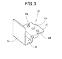
- Fig. 3 is a perspective view of a second shade unit shown in Fig. 1
- Fig. 4 shows exemplary diagrams showing light distribution patterns which are formed by the vehicle lamp shown in Fig. 1 .
- a vehicle lamp 1A of this embodiment is used as a vehicle headlamp. As shown in Fig. 1 , the vehicle lamp 1A includes a lamp body 100 and a transparent cover 101 which covers an opening portion in the lamp body 100. A lamp compartment S is defined by the lamp body 100 and the transparent cover 101, and constituent members, which will be described later, are accommodated in an interior of the lamp compartment S.
- the vehicle lamp 1A includes a light source bulb 10 having an optical axis Ax which extends in a front-to-rear direction of a vehicle which has a light source 11, a projection lens 30 that is disposed in front of the light source 11 and which project light from the light source 11 to a front side of the vehicle lamp 1A, a reflector 20 which reflects light from the light source 11 towards the optical axis Ax, a holder unit 25 which supports fixedly the projection lens 30 and the reflector 20, a first shade unit 40 (an example of a first shield member) and a second shade unit 50 (an example of a second shield member) which are both configured to cut off partially light from the light source 11 (light reflected by the reflector 20).
- a first shade unit 40 an example of a first shield member
- a second shade unit 50 an example of a second shield member
- the light source bulb 10 is disposed so that the light source 11 thereof is directed to face the interior of the lamp compartment S and is configured as a discharge bulb such as a metal halide bulb.
- a bulb socket 15 is attached integrally to a side of the light source bulb 10 which lies to face a rear side of the vehicle lamp 1A.
- the light source 11 of the light source bulb 10 is disposed further rearwards than a rear focal point F2 of the projection lens 30.
- the projection lens 30 is formed into a plano convex aspherical lens having a convex surface on a side facing the front side and a flat surface on a side facing the rear side of the vehicle lamp 1A and is disposed on the optical axis Ax.
- This projection lens 30 projects a light source image formed on the rear focal point F2 thereof on to an imaginary vertical screen disposed ahead of the vehicle lamp 1A as a reverted image.
- the reflector 20 has a bulb socket attaching portion 21 to which the bulb socket 15 of the light source bulb 10 can be attached and a reflection surface portion 22 which is provided integrally with the bulb socket attaching portion 21 on a side of the bulb attaching portion 21 which lies to face the vehicle lamp 1A.
- the light source 11 of the light source bulb 10 projects to the front side of the vehicle lamp 1A so that a light emitting portion thereof is substantially superposed on the optical axis Ax of the vehicle lamp 1A.
- the reflection surface portion 22 is provided so as to cover the light source 11 from above and sides and partially from below.
- An inner surface 22A of the reflection surface portion 22 which faces the light source 11 is formed into a smooth curved surface having a substantially elliptic cross section and functions as a reflection surface which reflects part of light from the light source 11 so as to cause the light reflected to converge towards near the rear focal point F2 of the projection lens 30.
- a first focal point F1 of the inner surface 22A of the reflection surface portion 22 coincides substantially with the position of a light emitting center of the light source in such a state that the projection lens 30, the holder unit 25, the reflector 20, and the first and second shade units 40, 50 are built in the lamp compartment S.
- a second focal point F2 of the inner surface 22A of the reflection surface portion 22 coincides substantially with the rear focal point of the projection lens 30 (hereinafter, the rear focal point of the projection lens 30 will also be referred to as the rear focal point F2).
- a material which can reflect, for example, incident light with high efficiency is deposited on the inner surface 22A of the reflection surface portion 22.
- the holder unit 25 has a holder main body 26 which is attached to the front of the reflector 20, a lens holder 29 that is disposed on a side of the reflector 20 which faces the front side of the vehicle lamp 1A and which holds the projection lens 30, and first and second connecting pieces 27, 28 which connect the lens holder 29 and the holder main body 26 together with a frame 41, which will be described later, of the first shade unit 40 held therebetween.
- a substantially flange-shaped fixing portion 26A is provided on the holder main body 26, and this fixing portion 26A fixedly supports the frame 41 (an example of a base plate) of the first shade unit 40.
- the lens holder 29 has a substantially cylindrical shape and is formed slightly larger than an outside diameter of the projection lens 30. The lens holder 29 fixedly supports the projection lens 30 in a predetermined position on a front end portion of the vehicle lamp 1A.
- the first connecting piece 27 is made up of a pair of plate-shaped members which are each provided integrally on an upper side of the lens holder 29 so as to extend from an upper side of a rear end portion of the lens holder 29 towards the rear of the vehicle lamp 1A.
- the second connecting piece 28 is made up of a pair of plate-shaped members which are each provided integrally on a lower side of the lens holder 29 so as to extend from a lower side of the rear end portion of the lens holder 29 towards the rear of the vehicle lamp 1A. Additionally, an extending portion 28A is formed on each of the pair of second connecting pieces 28 at a proximal end portion thereof which faces the lens holder 29 so as to extend in a radial direction of the lens holder 29.
- the first shade unit 40 is disposed near the rear focal point of the projection lens 30 and cuts off part of light from the light source 11 (refer to Fig. 1 ).
- the first shade unit 40 includes the frame 41 having a plate-like shape which is fixedly supported on the fixing portion 26A of the holder main body 26, two gear units 42, 42 individually connected to actuators 46 such as motors, and two shield plate portions 43a (for a low beam), 43b (for a high beam) that individually mesh with the corresponding gear units 42, 42 and which are rotatably held on the frame 41.
- a first through hole 44 is provided in an upper portion of the frame 41 for passage of light from the light source 11. Light from the light source 11 passes through the first through hole 44 to enter the projection lens 30.
- a second through hole 45 is also formed in a lower portion of the frame 41.
- a bridge portion 47 is formed between the first and second through holes 44, 45, and this bridge portion 47 bridges left and right end portions in a straight-line fashion.
- a support plate 48 (an example of a base plate) is provided at a substantially central lower end portion of the bridge portion 47 so as to extend to the rear of the vehicle lamp 1 (refer to Fig. 1 ).
- the two shield plate portions 43a, 43b of the first shade unit 40 are each rotated independently so as to overlap partially the first through hole 44 when viewed from the optical axis Ax, whereby the vehicle lamp 1A switches its light distribution patterns between at least one of a right high beam light distribution pattern and a left high beam light distribution pattern in both of which light from the light source 11 is partially cut off and at least one of a normal high beam light distribution pattern in which no light from the light source 11 is cut off and a low beam light distribution pattern.
- the second shade unit 50 is formed an integral unit by bending a metallic narrow elongated plate by using a press and has a shield plate portion (an example of a second shield member) 51, an attaching plate 52, and a connecting portion 53 which connects the first shield plate portion 51 and the attaching portion 52.
- the shield plate portion 51 has a rectangular plate shape and is provided so as to be normal to the optical axis Ax.
- the attaching portion 52 has a rectangular shape and is provided so that surfaces of the attaching portion 52 follow a horizontal direction.
- three through holes 52A are provided in a substantially central portion of the attaching portion 52.
- a middle portion of the attaching portion 52 is bent so as to be formed in a substantially L shape when viewed from a side thereof and is connected to the shield plate portion 51 and the attaching portion 52 along longitudinal edge portions thereof.
- the shield plate portion 51 of the second shade unit 50 cuts off a lower area of light from the light source 11 within the vehicle lamp 1A in a position which deviates from the second focal point F2 of the projection lens 30, as a result of which light of a high beam which illuminates an upper area of, for example, an imaginary vertical screen is cut off.
- Fig. 4 shows light distribution patterns which are supposed to be projected on to the imaginary vertical screen which is disposed in a position laid 25 m ahead of the vehicle lamp 1A.
- the imaginary vertical screen is specified by an original point O through which an optical axis passes, an H axis (an axis of abscissas) which specifies a horizontal direction and a V axis (an axis of ordinates) which specifies a vertical direction.
- the vehicle lamp 1A of this embodiment can form four light distribution patterns shown at (a) to (d) in Fig. 4 .
- Fig. 4(a) shows a normal low beam light distribution pattern LoC.
- This light distribution pattern is obtained by setting the first shade unit 40 of the vehicle lamp 1A in a low beam shining mode by a predetermined control unit.
- the low beam shield plate portion 43a takes a light cutting off posture (a posture in which it is laid horizontally as shown in Fig. 2 ) and the partially high beam shield plate portion 43b takes a retracted posture (a posture in which it is rotated slightly downwards from its horizontal position as shown in Fig. 2 ), as a result of which the low beam shield plate portion 43a partially overlaps a lower portion of the first through hole 44 in the frame 41, whereby light from the light source 11 is partially cut off by the overlapping portion to thereby obtain the light distribution pattern LoC.
- Fig. 4(b) shows a normal high beam light distribution pattern HiC.
- This light distribution pattern HiC is obtained by setting the first shade unit 40 of the vehicle lamp 1A in a high beam shining mode by the predetermined control unit. Namely, in the first shade unit 40, both the low beam shield plate portion 43a and the high beam shield plate portion 43b take the retracted postures, whereby they do not overlap the first through hole 44 in the frame 41, as a result of which light from the light source is not cut off by the shield plate portions 43a, 43b. On the other hand, the light which passes through the first through hole 44 is partially cut off by the shield plate portion 51 of the second shade unit 50.
- Fig. 4(c) shows a left high beam light distribution pattern HiCL
- Fig. 4(d) shows a right high beam light distribution pattern HiCR.
- this light distribution pattern HiCL areas of an H-V area other than an upper right-hand side area are illuminated, and hence, this light distribution pattern is one which is suitable for such a case that a preceding vehicle and a pedestrian do not exist on a lane where the subject vehicle is running while neither an oncoming vehicle nor a pedestrian exists on a lane for opposite traffic.
- this light distribution pattern is one which is suitable for such a case that neither a preceding vehicle nor a pedestrian exists on the subject vehicle's lane while an oncoming vehicle and a pedestrian exist on the opposite traffic's lane.
- the light distribution pattern HiCL With this light distribution pattern HiCR, the forward vision of the driver of the subject vehicle is ensured while the driver of the oncoming vehicle and the pedestrian on the opposite traffic's lane are both prevented from being dazzled by the glare of the headlamps of the subject vehicle.
- These light distribution patterns HiCL, HiCR are obtained by setting the first shade unit 40 of the vehicle lamp 1A is set in a right or left high beam shining mode by the predetermined control unit. Namely, in the first shade unit 40, of the two shield plate portions 43a, 43b, only the partial high beam shield plate portion 43 takes the light cutting off posture, in which the partial high beam shield plate portion 43b overlaps either of a left-hand side portion and a right-hand side portion of the lower portion of the first through hole 44 in the frame 41, whereby light from the light source 11 is partially cut off by the overlapping portion.
- part of light from the light source 11A passes through the first through hole 44 without being cut off by the shield plate portion 43 of the first shade unit 40.
- part of the light having passed so through the first through hole 44 travels towards an upper area, and part of the light illuminating the upper area is then cut off by the shield plate portion 51 of the second shade unit 50.
- the shield plate portion 51 of the second shade unit 50 is disposed in the position which is offset towards the front of the vehicle lamp 1A from the second focal point F2 of the projection lens 30, the upper left-hand side area FL (refer to Fig. 4(c) ) of the high beam or the upper right-hand side area FR (refer to Fig. 4(d) ) of the high beam is left unilluminated or cut off in such a state that the boundary between the illuminated area and the unilluminated area blurs.
- the vehicle lamp 1A that has been described heretofore is intended to be fitted in a left front or right front position of the vehicle and that the construction of the vehicle lamp 1A substantially remains the same whether it is disposed in the left front or right front position of the vehicle.
- the shapes of the shield plate portions 43a, 43b should be designed so as to form the left high beam light distribution pattern HiCL, whereas when the vehicle lamp 1A is such as to be disposed in the right front position of the vehicle, the shapes of the shield plate portions 43a, 43b should be designed so as to form the right high beam light distribution pattern HiCR.
- the shield plate portion 51 of the second shade unit 50 is disposed in the position which is spaced forwards by the predetermined distance away from the rear focal point F2 of the projection lens 30, and therefore, the boundary between the illuminated area and the unilluminated area blurs. Consequently, it becomes possible to reduce the risk of the driver feeling the sensation of physical disorder on the substantially upper area of the high beam when the high beam light distribution patterns are switched over.
- FIG. 5 is a perspective view illustrating a second embodiment of a vehicle lamp according to the invention.
- a second shade unit 60 of a vehicle lamp 1B of this embodiment is formed into an integral unit by bending a thin metallic plate by pressing and has a shield plate portion (an example of a second shield member) 61 which cuts off part of light from a light source 11, an attaching portion 62, and a connecting portion 63 which connects the shield plate portion 61 and the attaching portion 62 together.
- the shield plate portion 61 has a rectangular plate-like shape and is provided so as to be normal to an optical axis Ax.
- the attaching portion 62 is provided so that surfaces thereof become normal to the optical axis Ax.
- two through holes 62A are provided in each of left and right end portions of the attaching portion 62.
- the connecting portion 63 is provided so as to extend to the rear of the vehicle lamp 1B from an upper edge portion of a substantially central portion of the attaching portion 62 to connect to a proximal end portion of the shield plate portion 61.
- the second shade unit 60 of this embodiment is fixed to extending portions 28A of two connecting pieces 28, 28 of a lens holder 29 by inserting bolts (not shown) through the through holes 62A in the attaching portion 62 and tightening nuts on the bolts. Then, the shield plate portion 61 of the second shade unit 60 is fixedly supported in a position which is spaced by a predetermined distance forwards towards the front of the vehicle lamp 1B away from a rear focal point F2 of a projection lens 30.
- the second shade unit (the example of the second shield member) 60 is fixed to the lens holder 29, it is possible to realize an increase in working efficiency.
- Fig. 6 is a perspective view illustrating the vehicle lamp according to the third embodiment of the invention.
- a plurality of (four in this embodiment) rectangular through holes 29A are provided circumferentially at substantially equal intervals in an outer circumferential surface of a lens holder 29 of this embodiment.
- a second shade unit 70 is formed integrally by punching out a metallic piece having a desired shape from a thin metallic plate by pressing, and thereafter, the metallic piece so punched out is curved or bent.
- the second shade unit 70 so formed has a shied plate portion (an example of a second shield member) 71 which partially cuts off light from a light source 11, an attaching portion 72, and a connecting portion 73 which connects the shield plate portion 71 and the attaching portion 72 together.
- the shield plate portion 71 has a rectangular plate-like shape and is provided so that surfaces thereof become vertical to an optical axis Ax.
- An elastic force acts in the rounded second shade unit 70 in a direction in which the rounded second shade 70 is expanded diametrically.
- Rectangular fitting projecting portions (four in this embodiment) 72A are provided circumferentially at equal intervals on an outer circumferential surface of the attaching portion 72.
- the connecting portion 73 is provided so as to extend towards the rear of a vehicle lamp 1C from a lower end face portion of the attaching portion 72A of the attaching portion 72 to connect to a proximal end portion of the shield plate portion 71.
- the second shade unit 70 In attachment of the second shade unit 70, the second shade unit 70 is inserted in the lens holder 29 in such a state that the fitting projecting portions 72A on the attaching portion 72 coincide with the through holes 29A in the lens holder 29 in the circumferential direction, so that the fitting projecting portions 72A on the attaching portion 72 are fitted in the corresponding through holes 29A in the lens holder 29.
- the second shade unit 70 of this embodiment is attached to the lens holder 29 while being deflected to thereby be pressed against the lens holder 29 by virtue of the elastic force acting therein as a result of the deflection.
- the shield plate portion 71 of the second shade unit 70 is fixedly supported in a position which is spaced by a predetermined distance forwards towards the front of the vehicle lamp 1C away from a rear focal point F2 of a projection lens 30.
- the second shade unit (the example of the second shield member) 70 is made of up of the metallic member and is attached to the lens holder 29 while being deflected. Therefore, the necessity of fixing the second shade unit 70 to the lens holder 29 with bolts is obviated, improving the working efficiency. In addition, a reduction in production costs can be realized.
- the shield plate portion of the second shade unit may be provided in a position which is spaced rearwards towards the rear of the vehicle lamp by the predetermined distance away from the rear focal point of the projection lens, as long as the second shade unit deviates from the rear focal point of the projection lens.
Landscapes
- Engineering & Computer Science (AREA)
- General Engineering & Computer Science (AREA)
- Non-Portable Lighting Devices Or Systems Thereof (AREA)
Abstract
Description
- The present invention relates to a vehicle headlamp.
- In vehicle headlamps, there is known a vehicle headlamp which enables the switching of beam patterns or light distribution patterns thereof in order to attain both an increase in forward visibility of a driver of a vehicle and prevention of drivers of a preceding vehicle and an oncoming vehicle (hereinafter, both the vehicles being also referred to as a forward traveling vehicle) from being dazzled by the glare of the headlamps of the vehicle between a high beam light distribution pattern for illuminating the whole of an illumination area lying above a cut-off line of the headlamp and a partially cut off high beam light distribution pattern in which a portion of an illumination area which corresponds to the forward traveling vehicle is cut off (refer to
JP-A-2010-162960 - However, the results of visibility tests carried out in various kinds of road environments by the inventor have found out that when a right high beam light distribution pattern in which a left portion of the high beam is cut off, a left high beam light distribution pattern in which a right portion of the high beam is cut off and a normal high beam light distribution pattern in which no portion of the high beam is cut off are switched over in the environments where with a few street lights the forward vision of a vehicle is poorly lit, drivers participating the tests felt a sensation of physical disorder about near an upper portion of the illumination area of the high beam.
- An object of the invention is to provide a vehicle headlamp which can reduce the risk of a driver feeling a sensation of physical disorder when he or she switches the high beam light distribution patterns.
- One or more embodiments of the present invention provides a vehicle headlamp including a light source, a projection lens that is disposed in front of the light source and which projects light from the light source to the front, a first shield member that is disposed near a rear focal point of the projection lens and which can switch light distribution patterns between at least one of a right high beam light distribution pattern and a left high beam light distribution pattern in both of which light from the light source is partially cut off and at least one of a normal high beam light distribution pattern in which no part of light from the light source is cut off and a low beam pattern, and a second shield member that is disposed in a forward position or rearward position away from the rear focal point of the projection lens and which cuts off light of a high beam which illuminates an upper area.
- In addition, the vehicle headlamp of the invention includes a base plate which holds the first shield member, and the second shield member is fixed to the base plate.
- Additionally, the vehicle headlamp of the invention includes a lens holder which holds the projection lens, and the second shield member is fixed to the lens holder.
- Further, in the vehicle headlamp of the invention, the second shield member is made up of a metal member and is attached to the lens holder while being deflected.
- According to the vehicle headlamp of the invention, the light of the high beam which illuminates the upper area is cut off by the second shield member. In addition, the second shield member is disposed by the predetermined distance forwards or rearwards away from the rear focal point of the projection lens, and therefore, a boundary between the illuminated area and the unilluminated area blurs in the upper area of the high beam. Consequently, the sensation of physical disorder is reduced which is felt by the driver on the upper area of the high beam when the respective light distribution patterns of the high beams are switched over.
-
-
Fig. 1 is a vertical sectional view illustrating a first embodiment of a vehicle lamp according to the invention. -
Fig. 2 is an exploded perspective view of the vehicle lamp shown inFig. 1 . -
Fig. 3 is a perspective view of a second shade unit shown inFig. 1 . -
Fig. 4 shows exemplary diagrams showing light distribution patterns which are formed by the vehicle lamp shown inFig. 1 . -
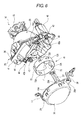
Fig. 5 is a perspective view illustrating a second embodiment of a vehicle lamp according to the embodiment. -
Fig. 6 is a perspective view illustrating a third embodiment of a vehicle lamp according to the invention. - Hereinafter, embodiments of the present invention will be described in detail with reference to the drawings. It should be noted that in each of the drawings used in the description below, in order to show constituent members in recognizable sizes, the reduction scale is changed as required. In embodiments of the invention, numerous specific details are set forth in order to provide a more thorough understanding of the invention. However, it will be apparent to one of ordinary skill in the art that the invention may be practiced without these specific details. In other instances, well-known features have not been described in detail to avoid obscuring the invention.
- Firstly, referring to
Figs. 1 to 4 , a vehicle lamp according to a first embodiment of the invention will be described.Fig. 1 is a vertical sectional view illustrating a first embodiment of a vehicle lamp according to the invention,Fig. 2 is an exploded perspective view of the vehicle lamp shown inFig. 1 ,Fig. 3 is a perspective view of a second shade unit shown inFig. 1 , andFig. 4 shows exemplary diagrams showing light distribution patterns which are formed by the vehicle lamp shown inFig. 1 . - A
vehicle lamp 1A of this embodiment is used as a vehicle headlamp. As shown inFig. 1 , thevehicle lamp 1A includes alamp body 100 and atransparent cover 101 which covers an opening portion in thelamp body 100. A lamp compartment S is defined by thelamp body 100 and thetransparent cover 101, and constituent members, which will be described later, are accommodated in an interior of the lamp compartment S. - As shown in
Figs. 1 and2 , thevehicle lamp 1A includes alight source bulb 10 having an optical axis Ax which extends in a front-to-rear direction of a vehicle which has alight source 11, aprojection lens 30 that is disposed in front of thelight source 11 and which project light from thelight source 11 to a front side of thevehicle lamp 1A, areflector 20 which reflects light from thelight source 11 towards the optical axis Ax, aholder unit 25 which supports fixedly theprojection lens 30 and thereflector 20, a first shade unit 40 (an example of a first shield member) and a second shade unit 50 (an example of a second shield member) which are both configured to cut off partially light from the light source 11 (light reflected by the reflector 20). - The
light source bulb 10 is disposed so that thelight source 11 thereof is directed to face the interior of the lamp compartment S and is configured as a discharge bulb such as a metal halide bulb. Abulb socket 15 is attached integrally to a side of thelight source bulb 10 which lies to face a rear side of thevehicle lamp 1A. Thelight source 11 of thelight source bulb 10 is disposed further rearwards than a rear focal point F2 of theprojection lens 30. - The
projection lens 30 is formed into a plano convex aspherical lens having a convex surface on a side facing the front side and a flat surface on a side facing the rear side of thevehicle lamp 1A and is disposed on the optical axis Ax. Thisprojection lens 30 projects a light source image formed on the rear focal point F2 thereof on to an imaginary vertical screen disposed ahead of thevehicle lamp 1A as a reverted image. - The
reflector 20 has a bulbsocket attaching portion 21 to which thebulb socket 15 of thelight source bulb 10 can be attached and areflection surface portion 22 which is provided integrally with the bulbsocket attaching portion 21 on a side of thebulb attaching portion 21 which lies to face thevehicle lamp 1A. As shown inFig. 1 , when thebulb socket 15 is attached to the bulbsocket attaching portion 21, thelight source 11 of thelight source bulb 10 projects to the front side of thevehicle lamp 1A so that a light emitting portion thereof is substantially superposed on the optical axis Ax of thevehicle lamp 1A. - The
reflection surface portion 22 is provided so as to cover thelight source 11 from above and sides and partially from below. Aninner surface 22A of thereflection surface portion 22 which faces thelight source 11 is formed into a smooth curved surface having a substantially elliptic cross section and functions as a reflection surface which reflects part of light from thelight source 11 so as to cause the light reflected to converge towards near the rear focal point F2 of theprojection lens 30. Namely, a first focal point F1 of theinner surface 22A of thereflection surface portion 22 coincides substantially with the position of a light emitting center of the light source in such a state that theprojection lens 30, theholder unit 25, thereflector 20, and the first andsecond shade units inner surface 22A of thereflection surface portion 22 coincides substantially with the rear focal point of the projection lens 30 (hereinafter, the rear focal point of theprojection lens 30 will also be referred to as the rear focal point F2). - Additionally, a material which can reflect, for example, incident light with high efficiency is deposited on the
inner surface 22A of thereflection surface portion 22. - The
holder unit 25 has a holdermain body 26 which is attached to the front of thereflector 20, alens holder 29 that is disposed on a side of thereflector 20 which faces the front side of thevehicle lamp 1A and which holds theprojection lens 30, and first and second connectingpieces lens holder 29 and the holdermain body 26 together with aframe 41, which will be described later, of thefirst shade unit 40 held therebetween. - A substantially flange-
shaped fixing portion 26A is provided on the holdermain body 26, and thisfixing portion 26A fixedly supports the frame 41 (an example of a base plate) of thefirst shade unit 40. Thelens holder 29 has a substantially cylindrical shape and is formed slightly larger than an outside diameter of theprojection lens 30. Thelens holder 29 fixedly supports theprojection lens 30 in a predetermined position on a front end portion of thevehicle lamp 1A. - The first connecting
piece 27 is made up of a pair of plate-shaped members which are each provided integrally on an upper side of thelens holder 29 so as to extend from an upper side of a rear end portion of thelens holder 29 towards the rear of thevehicle lamp 1A. The second connectingpiece 28 is made up of a pair of plate-shaped members which are each provided integrally on a lower side of thelens holder 29 so as to extend from a lower side of the rear end portion of thelens holder 29 towards the rear of thevehicle lamp 1A. Additionally, an extendingportion 28A is formed on each of the pair of second connectingpieces 28 at a proximal end portion thereof which faces thelens holder 29 so as to extend in a radial direction of thelens holder 29. - The
first shade unit 40 is disposed near the rear focal point of theprojection lens 30 and cuts off part of light from the light source 11 (refer toFig. 1 ). As shown inFig. 2 , thefirst shade unit 40 includes theframe 41 having a plate-like shape which is fixedly supported on thefixing portion 26A of the holdermain body 26, twogear units actuators 46 such as motors, and twoshield plate portions 43a (for a low beam), 43b (for a high beam) that individually mesh with thecorresponding gear units frame 41. A first throughhole 44 is provided in an upper portion of theframe 41 for passage of light from thelight source 11. Light from thelight source 11 passes through the first throughhole 44 to enter theprojection lens 30. - In addition, a second through
hole 45 is also formed in a lower portion of theframe 41. Abridge portion 47 is formed between the first and second throughholes bridge portion 47 bridges left and right end portions in a straight-line fashion. A support plate 48 (an example of a base plate) is provided at a substantially central lower end portion of thebridge portion 47 so as to extend to the rear of the vehicle lamp 1 (refer toFig. 1 ). - The two
shield plate portions first shade unit 40 are each rotated independently so as to overlap partially the first throughhole 44 when viewed from the optical axis Ax, whereby thevehicle lamp 1A switches its light distribution patterns between at least one of a right high beam light distribution pattern and a left high beam light distribution pattern in both of which light from thelight source 11 is partially cut off and at least one of a normal high beam light distribution pattern in which no light from thelight source 11 is cut off and a low beam light distribution pattern. - As shown in
Fig. 3 , thesecond shade unit 50 is formed an integral unit by bending a metallic narrow elongated plate by using a press and has a shield plate portion (an example of a second shield member) 51, an attachingplate 52, and a connectingportion 53 which connects the firstshield plate portion 51 and the attachingportion 52. Theshield plate portion 51 has a rectangular plate shape and is provided so as to be normal to the optical axis Ax. The attachingportion 52 has a rectangular shape and is provided so that surfaces of the attachingportion 52 follow a horizontal direction. In addition, three throughholes 52A are provided in a substantially central portion of the attachingportion 52. A middle portion of the attachingportion 52 is bent so as to be formed in a substantially L shape when viewed from a side thereof and is connected to theshield plate portion 51 and the attachingportion 52 along longitudinal edge portions thereof. - As shown in
Fig. 1 ,bolts 52B are inserted through the throughholes 52A in the attachingportion 52 and nuts are tightened on thebolts 52B, whereby thesecond shade unit 50 is fixed to thesupport plate 48 of theframe 41. Because of this, theshield plate portion 51 of thesecond shade unit 50 is fixedly supported in a position which is spaced by a predetermined distance forwards towards the front of the vehicle lamp 1 away from the rear focal point F2 of theprojection lens 30. Theshield plate portion 51 of thesecond shade unit 50 cuts off a lower area of light from thelight source 11 within thevehicle lamp 1A in a position which deviates from the second focal point F2 of theprojection lens 30, as a result of which light of a high beam which illuminates an upper area of, for example, an imaginary vertical screen is cut off. - Next, referring to
Fig. 4 , light distribution patterns will be described which can be illuminated or formed by thevehicle lamp 1A of this embodiment. - It should be noted that
Fig. 4 shows light distribution patterns which are supposed to be projected on to the imaginary vertical screen which is disposed in a position laid 25 m ahead of thevehicle lamp 1A. The imaginary vertical screen is specified by an original point O through which an optical axis passes, an H axis (an axis of abscissas) which specifies a horizontal direction and a V axis (an axis of ordinates) which specifies a vertical direction. - The
vehicle lamp 1A of this embodiment can form four light distribution patterns shown at (a) to (d) inFig. 4 . -
Fig. 4(a) shows a normal low beam light distribution pattern LoC. In this light distribution pattern LoC, there is no such situation that the driver of a forward traveling vehicle or a pedestrian is dazzled by the glare of thevehicle lamp 1A while the vehicle is driven in an urban area. This light distribution pattern is obtained by setting thefirst shade unit 40 of thevehicle lamp 1A in a low beam shining mode by a predetermined control unit. Namely, in thefirst shade unit 40, the low beamshield plate portion 43a takes a light cutting off posture (a posture in which it is laid horizontally as shown inFig. 2 ) and the partially high beamshield plate portion 43b takes a retracted posture (a posture in which it is rotated slightly downwards from its horizontal position as shown inFig. 2 ), as a result of which the low beamshield plate portion 43a partially overlaps a lower portion of the first throughhole 44 in theframe 41, whereby light from thelight source 11 is partially cut off by the overlapping portion to thereby obtain the light distribution pattern LoC. -
Fig. 4(b) shows a normal high beam light distribution pattern HiC. In this light distribution pattern HiC, the forward vision of the driver of the subject vehicle can be ensured to a maximum extent. This light distribution pattern HiC is obtained by setting thefirst shade unit 40 of thevehicle lamp 1A in a high beam shining mode by the predetermined control unit. Namely, in thefirst shade unit 40, both the low beamshield plate portion 43a and the high beamshield plate portion 43b take the retracted postures, whereby they do not overlap the first throughhole 44 in theframe 41, as a result of which light from the light source is not cut off by theshield plate portions hole 44 is partially cut off by theshield plate portion 51 of thesecond shade unit 50. As this occurs, since theshield plate portion 51 of thesecond shade unit 50 deviates towards the front of thevehicle lamp 1A from the rear focal point F2 of theprojection lens 30, an upper area FA of a high beam shone is cut off in such a state that a boundary between an illuminated area and an unilluminated area blurs. -
Fig. 4(c) shows a left high beam light distribution pattern HiCL, andFig. 4(d) shows a right high beam light distribution pattern HiCR. In this light distribution pattern HiCL, areas of an H-V area other than an upper right-hand side area are illuminated, and hence, this light distribution pattern is one which is suitable for such a case that a preceding vehicle and a pedestrian do not exist on a lane where the subject vehicle is running while neither an oncoming vehicle nor a pedestrian exists on a lane for opposite traffic. Thus, with this light distribution pattern HiCL, the forward vision of the driver of the subject vehicle is ensured while the driver of the oncoming vehicle and the pedestrian on the opposite traffic's lane are both prevented from being dazzled by the glare of the headlamps of the subject vehicle. - On the other hand, in the light distribution pattern HiCR, areas of the H-V area other than an upper left-hand side area are illuminated, and hence, this light distribution pattern is one which is suitable for such a case that neither a preceding vehicle nor a pedestrian exists on the subject vehicle's lane while an oncoming vehicle and a pedestrian exist on the opposite traffic's lane. As with the light distribution pattern HiCL, with this light distribution pattern HiCR, the forward vision of the driver of the subject vehicle is ensured while the driver of the oncoming vehicle and the pedestrian on the opposite traffic's lane are both prevented from being dazzled by the glare of the headlamps of the subject vehicle.
- These light distribution patterns HiCL, HiCR are obtained by setting the
first shade unit 40 of thevehicle lamp 1A is set in a right or left high beam shining mode by the predetermined control unit. Namely, in thefirst shade unit 40, of the twoshield plate portions shield plate portion 43b overlaps either of a left-hand side portion and a right-hand side portion of the lower portion of the first throughhole 44 in theframe 41, whereby light from thelight source 11 is partially cut off by the overlapping portion. Here, part of light from the light source 11A passes through the first throughhole 44 without being cut off by the shield plate portion 43 of thefirst shade unit 40. Then, part of the light having passed so through the first throughhole 44 travels towards an upper area, and part of the light illuminating the upper area is then cut off by theshield plate portion 51 of thesecond shade unit 50. As this occurs, since theshield plate portion 51 of thesecond shade unit 50 is disposed in the position which is offset towards the front of thevehicle lamp 1A from the second focal point F2 of theprojection lens 30, the upper left-hand side area FL (refer toFig. 4(c) ) of the high beam or the upper right-hand side area FR (refer toFig. 4(d) ) of the high beam is left unilluminated or cut off in such a state that the boundary between the illuminated area and the unilluminated area blurs. - It should be noted that the
vehicle lamp 1A that has been described heretofore is intended to be fitted in a left front or right front position of the vehicle and that the construction of thevehicle lamp 1A substantially remains the same whether it is disposed in the left front or right front position of the vehicle. When thevehicle lamp 1A is such as to be disposed in the left front position of the vehicle, the shapes of theshield plate portions vehicle lamp 1A is such as to be disposed in the right front position of the vehicle, the shapes of theshield plate portions - Thus, according to the
vehicle lamp 1A of this embodiment, in the normal high beam light distribution HiC, the left high beam light distribution pattern HiCL and the right high beam light distribution pattern HiCR, the light of the high beam which illuminates the upper area is cut off by thesecond shade unit 50. In addition, theshield plate portion 51 of thesecond shade unit 50 is disposed in the position which is spaced forwards by the predetermined distance away from the rear focal point F2 of theprojection lens 30, and therefore, the boundary between the illuminated area and the unilluminated area blurs. Consequently, it becomes possible to reduce the risk of the driver feeling the sensation of physical disorder on the substantially upper area of the high beam when the high beam light distribution patterns are switched over. - Next, a vehicle lamp according to a second embodiment of the invention will be described by reference to
Fig. 5. Fig. 5 is a perspective view illustrating a second embodiment of a vehicle lamp according to the invention. - It should be noted that like reference numerals will be given to constituent portions like to those of the first embodiment, and the description thereof will be omitted or made briefly.
- As shown in
Fig. 5 , asecond shade unit 60 of avehicle lamp 1B of this embodiment is formed into an integral unit by bending a thin metallic plate by pressing and has a shield plate portion (an example of a second shield member) 61 which cuts off part of light from alight source 11, an attachingportion 62, and a connectingportion 63 which connects theshield plate portion 61 and the attachingportion 62 together. Theshield plate portion 61 has a rectangular plate-like shape and is provided so as to be normal to an optical axis Ax. The attachingportion 62 is provided so that surfaces thereof become normal to the optical axis Ax. In addition, two throughholes 62A are provided in each of left and right end portions of the attachingportion 62. The connectingportion 63 is provided so as to extend to the rear of thevehicle lamp 1B from an upper edge portion of a substantially central portion of the attachingportion 62 to connect to a proximal end portion of theshield plate portion 61. - The
second shade unit 60 of this embodiment is fixed to extendingportions 28A of two connectingpieces lens holder 29 by inserting bolts (not shown) through the throughholes 62A in the attachingportion 62 and tightening nuts on the bolts. Then, theshield plate portion 61 of thesecond shade unit 60 is fixedly supported in a position which is spaced by a predetermined distance forwards towards the front of thevehicle lamp 1B away from a rear focal point F2 of aprojection lens 30. - The other configurations are similar to those of the first embodiment.
- Thus, as has been described above, according to the
vehicle lamp 1B of this embodiment, since the second shade unit (the example of the second shield member) 60 is fixed to thelens holder 29, it is possible to realize an increase in working efficiency. - The other working effects are similar to those of the first embodiment.
- Further, a vehicle lamp according to a third embodiment of the invention will be described by reference to
Fig. 6. Fig. 6 is a perspective view illustrating the vehicle lamp according to the third embodiment of the invention. - It should be noted that like reference numerals will be given to constituent portions like to those of the first embodiment, and the description thereof will be omitted or made briefly.
- A plurality of (four in this embodiment) rectangular through
holes 29A are provided circumferentially at substantially equal intervals in an outer circumferential surface of alens holder 29 of this embodiment. In addition, as shown inFig. 6 , asecond shade unit 70 is formed integrally by punching out a metallic piece having a desired shape from a thin metallic plate by pressing, and thereafter, the metallic piece so punched out is curved or bent. As shown inFig. 6 , thesecond shade unit 70 so formed has a shied plate portion (an example of a second shield member) 71 which partially cuts off light from alight source 11, an attachingportion 72, and a connectingportion 73 which connects theshield plate portion 71 and the attachingportion 72 together. Theshield plate portion 71 has a rectangular plate-like shape and is provided so that surfaces thereof become vertical to an optical axis Ax. An elastic force acts in the roundedsecond shade unit 70 in a direction in which the roundedsecond shade 70 is expanded diametrically. Rectangular fitting projecting portions (four in this embodiment) 72A are provided circumferentially at equal intervals on an outer circumferential surface of the attachingportion 72. The connectingportion 73 is provided so as to extend towards the rear of a vehicle lamp 1C from a lower end face portion of the attachingportion 72A of the attachingportion 72 to connect to a proximal end portion of theshield plate portion 71. - In attachment of the
second shade unit 70, thesecond shade unit 70 is inserted in thelens holder 29 in such a state that the fitting projectingportions 72A on the attachingportion 72 coincide with the throughholes 29A in thelens holder 29 in the circumferential direction, so that the fitting projectingportions 72A on the attachingportion 72 are fitted in the corresponding throughholes 29A in thelens holder 29. By dosing so, thesecond shade unit 70 of this embodiment is attached to thelens holder 29 while being deflected to thereby be pressed against thelens holder 29 by virtue of the elastic force acting therein as a result of the deflection. Additionally, theshield plate portion 71 of thesecond shade unit 70 is fixedly supported in a position which is spaced by a predetermined distance forwards towards the front of the vehicle lamp 1C away from a rear focal point F2 of aprojection lens 30. - The other configurations are similar to those of the first embodiment.
- Thus, according to the vehicle lamp 1C of this embodiment, the second shade unit (the example of the second shield member) 70 is made of up of the metallic member and is attached to the
lens holder 29 while being deflected. Therefore, the necessity of fixing thesecond shade unit 70 to thelens holder 29 with bolts is obviated, improving the working efficiency. In addition, a reduction in production costs can be realized. - The other working effects are similar to those of the first embodiment.
- It should be noted that the invention is not limited to the embodiments that have been illustrated heretofore and hence can be modified as required without departing from the spirit and scope of the invention.
- For example, in the embodiments, while the shield plate portion of the second shade unit is provided in the position which is spaced forwards towards the front of the vehicle lamp by the predetermined distance from the rear focal point of the projection lens, the shield plate portion of the second shade unit may be provided in a position which is spaced rearwards towards the rear of the vehicle lamp by the predetermined distance away from the rear focal point of the projection lens, as long as the second shade unit deviates from the rear focal point of the projection lens.
Claims (4)
- A vehicle headlamp comprising:a light source;a projection lens that is disposed in front of the light source and which projects light from the light source to the front;a first shield member that is disposed near a rear focal point of the projection lens and which can switch light distribution patterns between at least one of a right high beam light distribution pattern and a left high beam light distribution pattern in both of which light from the light source is partially cut off and at least one of a normal high beam light distribution pattern in which no part of light from the light source is cut off and a low beam pattern; anda second shield member that is disposed in a forward position or rearward position away from the rear focal point of the projection lens and which cuts off light of a high beam which illuminates an upper area.
- The vehicle headlamp according to Claim 1, comprising:a base plate which holds the first shield member, whereinthe second shield member is fixed to the base plate.
- The vehicle headlamp according to Claim 1, comprising:a lens holder which holds the projection lens, whereinthe second shield member is fixed to the lens holder.
- The vehicle lamp according to Claim 3, wherein
the second shield member is made up of a metal member and is attached to the lens holder while being deflected.
Applications Claiming Priority (1)
| Application Number | Priority Date | Filing Date | Title |
|---|---|---|---|
| JP2012105263A JP6059884B2 (en) | 2012-05-02 | 2012-05-02 | Vehicle headlamp |
Publications (3)
| Publication Number | Publication Date |
|---|---|
| EP2660506A2 true EP2660506A2 (en) | 2013-11-06 |
| EP2660506A3 EP2660506A3 (en) | 2018-03-28 |
| EP2660506B1 EP2660506B1 (en) | 2020-01-15 |
Family
ID=48182774
Family Applications (1)
| Application Number | Title | Priority Date | Filing Date |
|---|---|---|---|
| EP13165060.8A Active EP2660506B1 (en) | 2012-05-02 | 2013-04-24 | Vehicle headlamp |
Country Status (3)
| Country | Link |
|---|---|
| EP (1) | EP2660506B1 (en) |
| JP (1) | JP6059884B2 (en) |
| CN (1) | CN103381771B (en) |
Cited By (3)
| Publication number | Priority date | Publication date | Assignee | Title |
|---|---|---|---|---|
| CN105927913A (en) * | 2016-04-26 | 2016-09-07 | 华定谟 | High beam for automobile |
| CN106813186A (en) * | 2017-04-10 | 2017-06-09 | 海纳川海拉(三河)车灯有限公司 | Automobile-used LED dipped beam module and its application method |
| CN111981434A (en) * | 2018-05-31 | 2020-11-24 | 亳州易泽信息科技有限公司 | Transmission method of automobile hood for weakening influence of high beam during meeting |
Families Citing this family (7)
| Publication number | Priority date | Publication date | Assignee | Title |
|---|---|---|---|---|
| CN104390184A (en) * | 2014-09-30 | 2015-03-04 | 广东斯科电气股份有限公司 | Automobile LED (Light Emitting Diode) headlamp |
| CN104390186B (en) * | 2014-11-13 | 2016-10-12 | 宁波市鄞州雅佳达车业有限公司 | A kind of steering indicating light |
| CN104456352B (en) * | 2014-11-13 | 2017-02-15 | 宁波市鄞州雅佳达车业有限公司 | Steering lamp |
| CN106051585B (en) * | 2016-08-16 | 2018-04-27 | 常州星宇车灯股份有限公司 | The double optical lens modules of light collecting LED |
| CN106322277B (en) * | 2016-09-29 | 2019-04-30 | 北京汽车股份有限公司 | Headlight for vehicle and the vehicle with it |
| US11221122B2 (en) * | 2020-03-27 | 2022-01-11 | Nichia Corporation | Lighting device and headlight having a reflector, lenses and light-shielding members |
| US12072075B2 (en) | 2020-04-17 | 2024-08-27 | Hasco Vision Technology Co., Ltd. | Primary optical structure, high-beam lighting device, anti-glare high-beam lamp and vehicle |
Citations (1)
| Publication number | Priority date | Publication date | Assignee | Title |
|---|---|---|---|---|
| JP2010162960A (en) | 2009-01-13 | 2010-07-29 | Koito Mfg Co Ltd | Vehicle headlight device |
Family Cites Families (15)
| Publication number | Priority date | Publication date | Assignee | Title |
|---|---|---|---|---|
| JP4061233B2 (en) * | 2003-04-23 | 2008-03-12 | 株式会社小糸製作所 | Vehicle headlamp |
| JP4579154B2 (en) * | 2005-12-28 | 2010-11-10 | 株式会社小糸製作所 | Vehicle headlamp |
| JP4863502B2 (en) * | 2007-05-21 | 2012-01-25 | スタンレー電気株式会社 | Vehicle headlamp |
| CN201180925Y (en) * | 2008-02-19 | 2009-01-14 | 帝宝工业股份有限公司 | Car lamp apparatus capable of switching far and near lamp |
| JP5260098B2 (en) * | 2008-03-21 | 2013-08-14 | 株式会社小糸製作所 | Vehicle headlamp device |
| CN101585340A (en) * | 2008-05-23 | 2009-11-25 | 孙少珍 | Projection lamp for vehicle |
| CN201255337Y (en) * | 2008-05-23 | 2009-06-10 | 孙少珍 | Projection lamp for vehicle |
| JP2010000957A (en) * | 2008-06-20 | 2010-01-07 | Koito Mfg Co Ltd | Headlight device for vehicle |
| JP5107821B2 (en) * | 2008-08-07 | 2012-12-26 | 株式会社小糸製作所 | Vehicle headlamp device |
| CN201373339Y (en) * | 2009-03-16 | 2009-12-30 | 堤维西交通工业股份有限公司 | High and low beam switching device |
| JP2010257909A (en) * | 2009-04-28 | 2010-11-11 | Koito Mfg Co Ltd | Vehicle headlamp device |
| JP5468855B2 (en) * | 2009-09-16 | 2014-04-09 | 株式会社小糸製作所 | Vehicle headlamp lamp unit |
| JP5476074B2 (en) * | 2009-09-18 | 2014-04-23 | 株式会社小糸製作所 | Vehicle headlamp |
| JP5398507B2 (en) * | 2009-12-16 | 2014-01-29 | 株式会社小糸製作所 | Vehicle headlamp device |
| JP5539796B2 (en) * | 2010-06-24 | 2014-07-02 | 株式会社小糸製作所 | Vehicle headlight system |
-
2012
- 2012-05-02 JP JP2012105263A patent/JP6059884B2/en not_active Expired - Fee Related
-
2013
- 2013-04-24 EP EP13165060.8A patent/EP2660506B1/en active Active
- 2013-04-26 CN CN201310150327.2A patent/CN103381771B/en not_active Expired - Fee Related
Patent Citations (1)
| Publication number | Priority date | Publication date | Assignee | Title |
|---|---|---|---|---|
| JP2010162960A (en) | 2009-01-13 | 2010-07-29 | Koito Mfg Co Ltd | Vehicle headlight device |
Cited By (4)
| Publication number | Priority date | Publication date | Assignee | Title |
|---|---|---|---|---|
| CN105927913A (en) * | 2016-04-26 | 2016-09-07 | 华定谟 | High beam for automobile |
| CN106813186A (en) * | 2017-04-10 | 2017-06-09 | 海纳川海拉(三河)车灯有限公司 | Automobile-used LED dipped beam module and its application method |
| CN111981434A (en) * | 2018-05-31 | 2020-11-24 | 亳州易泽信息科技有限公司 | Transmission method of automobile hood for weakening influence of high beam during meeting |
| CN111981434B (en) * | 2018-05-31 | 2021-11-30 | 亳州易泽信息科技有限公司 | Transmission method of automobile hood for weakening influence of high beam during meeting |
Also Published As
| Publication number | Publication date |
|---|---|
| EP2660506A3 (en) | 2018-03-28 |
| CN103381771B (en) | 2015-11-18 |
| EP2660506B1 (en) | 2020-01-15 |
| JP6059884B2 (en) | 2017-01-11 |
| CN103381771A (en) | 2013-11-06 |
| JP2013235650A (en) | 2013-11-21 |
Similar Documents
| Publication | Publication Date | Title |
|---|---|---|
| EP2660506B1 (en) | Vehicle headlamp | |
| CN103574460B (en) | Vehicle headlamp | |
| JP5053890B2 (en) | Vehicle lamp | |
| EP2455656B1 (en) | Vehicle headlamp | |
| JP6677539B2 (en) | Lighting device with optical waveguide | |
| CN102374468A (en) | Vehicle headlamp | |
| JP2009179113A (en) | Vehicle headlamp device and control method thereof | |
| CN114877286A (en) | Lighting device for a motor vehicle comprising a light guide | |
| US20120140503A1 (en) | Head Lamp for Vehicle | |
| JP2000021227A (en) | Vehicle headlights | |
| JP2013097874A (en) | Vehicle lighting fixture | |
| CN102099618B (en) | Projector modules for headlights | |
| JP2013127963A (en) | Lighting module for generating interlacing of light strip | |
| JP3553471B2 (en) | Vehicle headlights | |
| JPH1186606A (en) | Vehicle headlights | |
| US7287887B2 (en) | Vehicle headlamp | |
| US20160069528A1 (en) | Lighting module for motor vehicle headlight, headlight equipped with such modules, and headlight assembly | |
| EP2230128A1 (en) | Automotive headlamp apparatus for controlling light distribution pattern | |
| CN107448867B (en) | ADB module | |
| JP2002109915A (en) | Vehicle headlights | |
| CN109210484B (en) | Lighting device for a motor vehicle | |
| JPH05266701A (en) | Vehicle headlight device | |
| JPH11144501A (en) | Vehicle headlights | |
| JP5723418B2 (en) | Vehicle headlamp | |
| JP5869807B2 (en) | Projector type headlamp |
Legal Events
| Date | Code | Title | Description |
|---|---|---|---|
| PUAI | Public reference made under article 153(3) epc to a published international application that has entered the european phase |
Free format text: ORIGINAL CODE: 0009012 |
|
| 17P | Request for examination filed |
Effective date: 20130424 |
|
| AK | Designated contracting states |
Kind code of ref document: A2 Designated state(s): AL AT BE BG CH CY CZ DE DK EE ES FI FR GB GR HR HU IE IS IT LI LT LU LV MC MK MT NL NO PL PT RO RS SE SI SK SM TR |
|
| AX | Request for extension of the european patent |
Extension state: BA ME |
|
| PUAL | Search report despatched |
Free format text: ORIGINAL CODE: 0009013 |
|
| AK | Designated contracting states |
Kind code of ref document: A3 Designated state(s): AL AT BE BG CH CY CZ DE DK EE ES FI FR GB GR HR HU IE IS IT LI LT LU LV MC MK MT NL NO PL PT RO RS SE SI SK SM TR |
|
| AX | Request for extension of the european patent |
Extension state: BA ME |
|
| RIC1 | Information provided on ipc code assigned before grant |
Ipc: F21S 8/10 00000000AFI20180220BHEP |
|
| RIC1 | Information provided on ipc code assigned before grant |
Ipc: F21S 8/10 20181130AFI20180220BHEP |
|
| RIC1 | Information provided on ipc code assigned before grant |
Ipc: F21S 8/10 20060101AFI20180220BHEP |
|
| REG | Reference to a national code |
Ref country code: DE Ref legal event code: R079 Ref document number: 602013065051 Country of ref document: DE Free format text: PREVIOUS MAIN CLASS: F21S0008100000 Ipc: F21S0041686000 |
|
| GRAP | Despatch of communication of intention to grant a patent |
Free format text: ORIGINAL CODE: EPIDOSNIGR1 |
|
| STAA | Information on the status of an ep patent application or granted ep patent |
Free format text: STATUS: GRANT OF PATENT IS INTENDED |
|
| RIC1 | Information provided on ipc code assigned before grant |
Ipc: F21W 102/14 20180101ALI20190709BHEP Ipc: F21S 41/172 20180101ALI20190709BHEP Ipc: F21S 41/689 20180101ALI20190709BHEP Ipc: F21S 41/255 20180101ALI20190709BHEP Ipc: F21S 41/43 20180101ALI20190709BHEP Ipc: F21S 41/686 20180101AFI20190709BHEP Ipc: F21S 41/47 20180101ALI20190709BHEP |
|
| INTG | Intention to grant announced |
Effective date: 20190814 |
|
| GRAS | Grant fee paid |
Free format text: ORIGINAL CODE: EPIDOSNIGR3 |
|
| GRAA | (expected) grant |
Free format text: ORIGINAL CODE: 0009210 |
|
| STAA | Information on the status of an ep patent application or granted ep patent |
Free format text: STATUS: THE PATENT HAS BEEN GRANTED |
|
| AK | Designated contracting states |
Kind code of ref document: B1 Designated state(s): AL AT BE BG CH CY CZ DE DK EE ES FI FR GB GR HR HU IE IS IT LI LT LU LV MC MK MT NL NO PL PT RO RS SE SI SK SM TR |
|
| REG | Reference to a national code |
Ref country code: CH Ref legal event code: EP Ref country code: GB Ref legal event code: FG4D |
|
| REG | Reference to a national code |
Ref country code: IE Ref legal event code: FG4D |
|
| REG | Reference to a national code |
Ref country code: DE Ref legal event code: R096 Ref document number: 602013065051 Country of ref document: DE |
|
| REG | Reference to a national code |
Ref country code: AT Ref legal event code: REF Ref document number: 1225465 Country of ref document: AT Kind code of ref document: T Effective date: 20200215 |
|
| REG | Reference to a national code |
Ref country code: NL Ref legal event code: MP Effective date: 20200115 |
|
| REG | Reference to a national code |
Ref country code: LT Ref legal event code: MG4D |
|
| PG25 | Lapsed in a contracting state [announced via postgrant information from national office to epo] |
Ref country code: NL Free format text: LAPSE BECAUSE OF FAILURE TO SUBMIT A TRANSLATION OF THE DESCRIPTION OR TO PAY THE FEE WITHIN THE PRESCRIBED TIME-LIMIT Effective date: 20200115 Ref country code: RS Free format text: LAPSE BECAUSE OF FAILURE TO SUBMIT A TRANSLATION OF THE DESCRIPTION OR TO PAY THE FEE WITHIN THE PRESCRIBED TIME-LIMIT Effective date: 20200115 Ref country code: NO Free format text: LAPSE BECAUSE OF FAILURE TO SUBMIT A TRANSLATION OF THE DESCRIPTION OR TO PAY THE FEE WITHIN THE PRESCRIBED TIME-LIMIT Effective date: 20200415 Ref country code: FI Free format text: LAPSE BECAUSE OF FAILURE TO SUBMIT A TRANSLATION OF THE DESCRIPTION OR TO PAY THE FEE WITHIN THE PRESCRIBED TIME-LIMIT Effective date: 20200115 Ref country code: PT Free format text: LAPSE BECAUSE OF FAILURE TO SUBMIT A TRANSLATION OF THE DESCRIPTION OR TO PAY THE FEE WITHIN THE PRESCRIBED TIME-LIMIT Effective date: 20200607 |
|
| PG25 | Lapsed in a contracting state [announced via postgrant information from national office to epo] |
Ref country code: LV Free format text: LAPSE BECAUSE OF FAILURE TO SUBMIT A TRANSLATION OF THE DESCRIPTION OR TO PAY THE FEE WITHIN THE PRESCRIBED TIME-LIMIT Effective date: 20200115 Ref country code: SE Free format text: LAPSE BECAUSE OF FAILURE TO SUBMIT A TRANSLATION OF THE DESCRIPTION OR TO PAY THE FEE WITHIN THE PRESCRIBED TIME-LIMIT Effective date: 20200115 Ref country code: HR Free format text: LAPSE BECAUSE OF FAILURE TO SUBMIT A TRANSLATION OF THE DESCRIPTION OR TO PAY THE FEE WITHIN THE PRESCRIBED TIME-LIMIT Effective date: 20200115 Ref country code: BG Free format text: LAPSE BECAUSE OF FAILURE TO SUBMIT A TRANSLATION OF THE DESCRIPTION OR TO PAY THE FEE WITHIN THE PRESCRIBED TIME-LIMIT Effective date: 20200415 Ref country code: IS Free format text: LAPSE BECAUSE OF FAILURE TO SUBMIT A TRANSLATION OF THE DESCRIPTION OR TO PAY THE FEE WITHIN THE PRESCRIBED TIME-LIMIT Effective date: 20200515 Ref country code: GR Free format text: LAPSE BECAUSE OF FAILURE TO SUBMIT A TRANSLATION OF THE DESCRIPTION OR TO PAY THE FEE WITHIN THE PRESCRIBED TIME-LIMIT Effective date: 20200416 |
|
| REG | Reference to a national code |
Ref country code: DE Ref legal event code: R097 Ref document number: 602013065051 Country of ref document: DE |
|
| PG25 | Lapsed in a contracting state [announced via postgrant information from national office to epo] |
Ref country code: SK Free format text: LAPSE BECAUSE OF FAILURE TO SUBMIT A TRANSLATION OF THE DESCRIPTION OR TO PAY THE FEE WITHIN THE PRESCRIBED TIME-LIMIT Effective date: 20200115 Ref country code: RO Free format text: LAPSE BECAUSE OF FAILURE TO SUBMIT A TRANSLATION OF THE DESCRIPTION OR TO PAY THE FEE WITHIN THE PRESCRIBED TIME-LIMIT Effective date: 20200115 Ref country code: LT Free format text: LAPSE BECAUSE OF FAILURE TO SUBMIT A TRANSLATION OF THE DESCRIPTION OR TO PAY THE FEE WITHIN THE PRESCRIBED TIME-LIMIT Effective date: 20200115 Ref country code: DK Free format text: LAPSE BECAUSE OF FAILURE TO SUBMIT A TRANSLATION OF THE DESCRIPTION OR TO PAY THE FEE WITHIN THE PRESCRIBED TIME-LIMIT Effective date: 20200115 Ref country code: ES Free format text: LAPSE BECAUSE OF FAILURE TO SUBMIT A TRANSLATION OF THE DESCRIPTION OR TO PAY THE FEE WITHIN THE PRESCRIBED TIME-LIMIT Effective date: 20200115 Ref country code: EE Free format text: LAPSE BECAUSE OF FAILURE TO SUBMIT A TRANSLATION OF THE DESCRIPTION OR TO PAY THE FEE WITHIN THE PRESCRIBED TIME-LIMIT Effective date: 20200115 Ref country code: CZ Free format text: LAPSE BECAUSE OF FAILURE TO SUBMIT A TRANSLATION OF THE DESCRIPTION OR TO PAY THE FEE WITHIN THE PRESCRIBED TIME-LIMIT Effective date: 20200115 Ref country code: SM Free format text: LAPSE BECAUSE OF FAILURE TO SUBMIT A TRANSLATION OF THE DESCRIPTION OR TO PAY THE FEE WITHIN THE PRESCRIBED TIME-LIMIT Effective date: 20200115 |
|
| REG | Reference to a national code |
Ref country code: DE Ref legal event code: R119 Ref document number: 602013065051 Country of ref document: DE |
|
| REG | Reference to a national code |
Ref country code: AT Ref legal event code: MK05 Ref document number: 1225465 Country of ref document: AT Kind code of ref document: T Effective date: 20200115 |
|
| PLBE | No opposition filed within time limit |
Free format text: ORIGINAL CODE: 0009261 |
|
| STAA | Information on the status of an ep patent application or granted ep patent |
Free format text: STATUS: NO OPPOSITION FILED WITHIN TIME LIMIT |
|
| PG25 | Lapsed in a contracting state [announced via postgrant information from national office to epo] |
Ref country code: MC Free format text: LAPSE BECAUSE OF FAILURE TO SUBMIT A TRANSLATION OF THE DESCRIPTION OR TO PAY THE FEE WITHIN THE PRESCRIBED TIME-LIMIT Effective date: 20200115 |
|
| REG | Reference to a national code |
Ref country code: CH Ref legal event code: PL |
|
| 26N | No opposition filed |
Effective date: 20201016 |
|
| PG25 | Lapsed in a contracting state [announced via postgrant information from national office to epo] |
Ref country code: CH Free format text: LAPSE BECAUSE OF NON-PAYMENT OF DUE FEES Effective date: 20200430 Ref country code: DE Free format text: LAPSE BECAUSE OF NON-PAYMENT OF DUE FEES Effective date: 20201103 Ref country code: IT Free format text: LAPSE BECAUSE OF FAILURE TO SUBMIT A TRANSLATION OF THE DESCRIPTION OR TO PAY THE FEE WITHIN THE PRESCRIBED TIME-LIMIT Effective date: 20200115 Ref country code: LI Free format text: LAPSE BECAUSE OF NON-PAYMENT OF DUE FEES Effective date: 20200430 Ref country code: LU Free format text: LAPSE BECAUSE OF NON-PAYMENT OF DUE FEES Effective date: 20200424 Ref country code: AT Free format text: LAPSE BECAUSE OF FAILURE TO SUBMIT A TRANSLATION OF THE DESCRIPTION OR TO PAY THE FEE WITHIN THE PRESCRIBED TIME-LIMIT Effective date: 20200115 Ref country code: FR Free format text: LAPSE BECAUSE OF NON-PAYMENT OF DUE FEES Effective date: 20200430 |
|
| REG | Reference to a national code |
Ref country code: BE Ref legal event code: MM Effective date: 20200430 |
|
| PG25 | Lapsed in a contracting state [announced via postgrant information from national office to epo] |
Ref country code: SI Free format text: LAPSE BECAUSE OF FAILURE TO SUBMIT A TRANSLATION OF THE DESCRIPTION OR TO PAY THE FEE WITHIN THE PRESCRIBED TIME-LIMIT Effective date: 20200115 Ref country code: BE Free format text: LAPSE BECAUSE OF NON-PAYMENT OF DUE FEES Effective date: 20200430 Ref country code: PL Free format text: LAPSE BECAUSE OF FAILURE TO SUBMIT A TRANSLATION OF THE DESCRIPTION OR TO PAY THE FEE WITHIN THE PRESCRIBED TIME-LIMIT Effective date: 20200115 |
|
| GBPC | Gb: european patent ceased through non-payment of renewal fee |
Effective date: 20200424 |
|
| PG25 | Lapsed in a contracting state [announced via postgrant information from national office to epo] |
Ref country code: IE Free format text: LAPSE BECAUSE OF NON-PAYMENT OF DUE FEES Effective date: 20200424 Ref country code: GB Free format text: LAPSE BECAUSE OF NON-PAYMENT OF DUE FEES Effective date: 20200424 |
|
| PG25 | Lapsed in a contracting state [announced via postgrant information from national office to epo] |
Ref country code: TR Free format text: LAPSE BECAUSE OF FAILURE TO SUBMIT A TRANSLATION OF THE DESCRIPTION OR TO PAY THE FEE WITHIN THE PRESCRIBED TIME-LIMIT Effective date: 20200115 Ref country code: MT Free format text: LAPSE BECAUSE OF FAILURE TO SUBMIT A TRANSLATION OF THE DESCRIPTION OR TO PAY THE FEE WITHIN THE PRESCRIBED TIME-LIMIT Effective date: 20200115 Ref country code: CY Free format text: LAPSE BECAUSE OF FAILURE TO SUBMIT A TRANSLATION OF THE DESCRIPTION OR TO PAY THE FEE WITHIN THE PRESCRIBED TIME-LIMIT Effective date: 20200115 |
|
| PG25 | Lapsed in a contracting state [announced via postgrant information from national office to epo] |
Ref country code: MK Free format text: LAPSE BECAUSE OF FAILURE TO SUBMIT A TRANSLATION OF THE DESCRIPTION OR TO PAY THE FEE WITHIN THE PRESCRIBED TIME-LIMIT Effective date: 20200115 Ref country code: AL Free format text: LAPSE BECAUSE OF FAILURE TO SUBMIT A TRANSLATION OF THE DESCRIPTION OR TO PAY THE FEE WITHIN THE PRESCRIBED TIME-LIMIT Effective date: 20200115 |