EP2660369A1 - Composite spinneret and method of manufacturing composite fiber - Google Patents
Composite spinneret and method of manufacturing composite fiber Download PDFInfo
- Publication number
- EP2660369A1 EP2660369A1 EP11853367.8A EP11853367A EP2660369A1 EP 2660369 A1 EP2660369 A1 EP 2660369A1 EP 11853367 A EP11853367 A EP 11853367A EP 2660369 A1 EP2660369 A1 EP 2660369A1
- Authority
- EP
- European Patent Office
- Prior art keywords
- discharge holes
- component discharge
- island component
- hole
- polymer
- Prior art date
- Legal status (The legal status is an assumption and is not a legal conclusion. Google has not performed a legal analysis and makes no representation as to the accuracy of the status listed.)
- Granted
Links
- 239000002131 composite material Substances 0.000 title claims abstract description 300
- 239000000835 fiber Substances 0.000 title claims abstract description 219
- 238000004519 manufacturing process Methods 0.000 title claims abstract description 46
- 229920000642 polymer Polymers 0.000 claims abstract description 481
- 238000009826 distribution Methods 0.000 claims abstract description 424
- 238000009987 spinning Methods 0.000 claims abstract description 141
- 238000012856 packing Methods 0.000 claims abstract description 70
- 238000007599 discharging Methods 0.000 claims abstract description 20
- 238000011144 upstream manufacturing Methods 0.000 claims description 22
- 238000002074 melt spinning Methods 0.000 claims description 11
- 238000005304 joining Methods 0.000 abstract description 62
- 230000001965 increasing effect Effects 0.000 abstract description 58
- 239000000306 component Substances 0.000 description 903
- 238000000034 method Methods 0.000 description 36
- 238000012545 processing Methods 0.000 description 23
- 229920001410 Microfiber Polymers 0.000 description 21
- 238000001816 cooling Methods 0.000 description 18
- 238000010030 laminating Methods 0.000 description 15
- 229920000139 polyethylene terephthalate Polymers 0.000 description 14
- 239000005020 polyethylene terephthalate Substances 0.000 description 14
- 238000004891 communication Methods 0.000 description 13
- 230000000052 comparative effect Effects 0.000 description 13
- 238000005516 engineering process Methods 0.000 description 11
- 230000002829 reductive effect Effects 0.000 description 10
- 238000005530 etching Methods 0.000 description 9
- RKTYLMNFRDHKIL-UHFFFAOYSA-N copper;5,10,15,20-tetraphenylporphyrin-22,24-diide Chemical compound [Cu+2].C1=CC(C(=C2C=CC([N-]2)=C(C=2C=CC=CC=2)C=2C=CC(N=2)=C(C=2C=CC=CC=2)C2=CC=C3[N-]2)C=2C=CC=CC=2)=NC1=C3C1=CC=CC=C1 RKTYLMNFRDHKIL-UHFFFAOYSA-N 0.000 description 8
- 230000000694 effects Effects 0.000 description 8
- 239000011295 pitch Substances 0.000 description 8
- 230000000670 limiting effect Effects 0.000 description 7
- HEMHJVSKTPXQMS-UHFFFAOYSA-M Sodium hydroxide Chemical compound [OH-].[Na+] HEMHJVSKTPXQMS-UHFFFAOYSA-M 0.000 description 6
- 238000005452 bending Methods 0.000 description 6
- 230000008901 benefit Effects 0.000 description 6
- 230000003247 decreasing effect Effects 0.000 description 6
- 239000012770 industrial material Substances 0.000 description 6
- -1 polyethylene Polymers 0.000 description 6
- 238000010438 heat treatment Methods 0.000 description 5
- 238000003780 insertion Methods 0.000 description 5
- 230000037431 insertion Effects 0.000 description 5
- 239000000463 material Substances 0.000 description 5
- 239000000155 melt Substances 0.000 description 5
- 239000003921 oil Substances 0.000 description 5
- 239000000243 solution Substances 0.000 description 5
- 239000004952 Polyamide Substances 0.000 description 4
- 229910045601 alloy Inorganic materials 0.000 description 4
- 239000000956 alloy Substances 0.000 description 4
- 239000007864 aqueous solution Substances 0.000 description 4
- 238000002844 melting Methods 0.000 description 4
- 230000008018 melting Effects 0.000 description 4
- 229920002647 polyamide Polymers 0.000 description 4
- 239000004753 textile Substances 0.000 description 4
- 230000002159 abnormal effect Effects 0.000 description 3
- 238000005299 abrasion Methods 0.000 description 3
- 239000003795 chemical substances by application Substances 0.000 description 3
- 239000008358 core component Substances 0.000 description 3
- 238000004043 dyeing Methods 0.000 description 3
- 239000004744 fabric Substances 0.000 description 3
- 238000011835 investigation Methods 0.000 description 3
- 230000014759 maintenance of location Effects 0.000 description 3
- 230000007246 mechanism Effects 0.000 description 3
- 229910052751 metal Inorganic materials 0.000 description 3
- 239000002184 metal Substances 0.000 description 3
- 239000002121 nanofiber Substances 0.000 description 3
- 229920000728 polyester Polymers 0.000 description 3
- 238000003672 processing method Methods 0.000 description 3
- 239000000523 sample Substances 0.000 description 3
- 239000004698 Polyethylene Substances 0.000 description 2
- 239000004734 Polyphenylene sulfide Substances 0.000 description 2
- GWEVSGVZZGPLCZ-UHFFFAOYSA-N Titan oxide Chemical compound O=[Ti]=O GWEVSGVZZGPLCZ-UHFFFAOYSA-N 0.000 description 2
- 239000003513 alkali Substances 0.000 description 2
- 238000004364 calculation method Methods 0.000 description 2
- 230000008859 change Effects 0.000 description 2
- 238000007334 copolymerization reaction Methods 0.000 description 2
- 238000002788 crimping Methods 0.000 description 2
- 230000002950 deficient Effects 0.000 description 2
- 229910003460 diamond Inorganic materials 0.000 description 2
- 239000010432 diamond Substances 0.000 description 2
- 239000003822 epoxy resin Substances 0.000 description 2
- 238000011156 evaluation Methods 0.000 description 2
- 230000001747 exhibiting effect Effects 0.000 description 2
- 239000012520 frozen sample Substances 0.000 description 2
- 230000009477 glass transition Effects 0.000 description 2
- 238000004898 kneading Methods 0.000 description 2
- 238000003754 machining Methods 0.000 description 2
- 238000005259 measurement Methods 0.000 description 2
- 230000036961 partial effect Effects 0.000 description 2
- 239000002245 particle Substances 0.000 description 2
- 229920000647 polyepoxide Polymers 0.000 description 2
- 229920000573 polyethylene Polymers 0.000 description 2
- 229920000098 polyolefin Polymers 0.000 description 2
- 229920000069 polyphenylene sulfide Polymers 0.000 description 2
- 230000002265 prevention Effects 0.000 description 2
- 239000000126 substance Substances 0.000 description 2
- 239000000758 substrate Substances 0.000 description 2
- XLYOFNOQVPJJNP-UHFFFAOYSA-N water Substances O XLYOFNOQVPJJNP-UHFFFAOYSA-N 0.000 description 2
- 238000003466 welding Methods 0.000 description 2
- ISPYQTSUDJAMAB-UHFFFAOYSA-N 2-chlorophenol Chemical compound OC1=CC=CC=C1Cl ISPYQTSUDJAMAB-UHFFFAOYSA-N 0.000 description 1
- 241000251468 Actinopterygii Species 0.000 description 1
- 229910000838 Al alloy Inorganic materials 0.000 description 1
- 239000005995 Aluminium silicate Substances 0.000 description 1
- 229920000742 Cotton Polymers 0.000 description 1
- 239000004743 Polypropylene Substances 0.000 description 1
- 239000004793 Polystyrene Substances 0.000 description 1
- VYPSYNLAJGMNEJ-UHFFFAOYSA-N Silicium dioxide Chemical compound O=[Si]=O VYPSYNLAJGMNEJ-UHFFFAOYSA-N 0.000 description 1
- 238000010521 absorption reaction Methods 0.000 description 1
- 230000009471 action Effects 0.000 description 1
- 239000000654 additive Substances 0.000 description 1
- 238000005273 aeration Methods 0.000 description 1
- 238000004220 aggregation Methods 0.000 description 1
- 230000002776 aggregation Effects 0.000 description 1
- 239000012773 agricultural material Substances 0.000 description 1
- 235000012211 aluminium silicate Nutrition 0.000 description 1
- 239000003963 antioxidant agent Substances 0.000 description 1
- 230000005540 biological transmission Effects 0.000 description 1
- 238000007664 blowing Methods 0.000 description 1
- 239000003518 caustics Substances 0.000 description 1
- 238000006243 chemical reaction Methods 0.000 description 1
- 238000005260 corrosion Methods 0.000 description 1
- 239000002781 deodorant agent Substances 0.000 description 1
- 238000013461 design Methods 0.000 description 1
- 238000011161 development Methods 0.000 description 1
- 238000009792 diffusion process Methods 0.000 description 1
- 239000006185 dispersion Substances 0.000 description 1
- 238000005553 drilling Methods 0.000 description 1
- 238000001035 drying Methods 0.000 description 1
- 239000000428 dust Substances 0.000 description 1
- 229920001971 elastomer Polymers 0.000 description 1
- 230000002708 enhancing effect Effects 0.000 description 1
- 239000012530 fluid Substances 0.000 description 1
- 238000001891 gel spinning Methods 0.000 description 1
- 239000011521 glass Substances 0.000 description 1
- 230000005484 gravity Effects 0.000 description 1
- 229920006158 high molecular weight polymer Polymers 0.000 description 1
- 230000007062 hydrolysis Effects 0.000 description 1
- 238000006460 hydrolysis reaction Methods 0.000 description 1
- NLYAJNPCOHFWQQ-UHFFFAOYSA-N kaolin Chemical compound O.O.O=[Al]O[Si](=O)O[Si](=O)O[Al]=O NLYAJNPCOHFWQQ-UHFFFAOYSA-N 0.000 description 1
- 238000009940 knitting Methods 0.000 description 1
- 239000007788 liquid Substances 0.000 description 1
- 230000007774 longterm Effects 0.000 description 1
- 230000000873 masking effect Effects 0.000 description 1
- 238000002156 mixing Methods 0.000 description 1
- 239000003607 modifier Substances 0.000 description 1
- 239000012299 nitrogen atmosphere Substances 0.000 description 1
- 239000004745 nonwoven fabric Substances 0.000 description 1
- 150000002894 organic compounds Chemical class 0.000 description 1
- 239000000123 paper Substances 0.000 description 1
- 230000000704 physical effect Effects 0.000 description 1
- 239000000049 pigment Substances 0.000 description 1
- 238000005498 polishing Methods 0.000 description 1
- 229920006149 polyester-amide block copolymer Polymers 0.000 description 1
- 239000004626 polylactic acid Substances 0.000 description 1
- 229920001155 polypropylene Polymers 0.000 description 1
- 229920002223 polystyrene Polymers 0.000 description 1
- 238000001556 precipitation Methods 0.000 description 1
- 238000002360 preparation method Methods 0.000 description 1
- 230000009467 reduction Effects 0.000 description 1
- 230000003014 reinforcing effect Effects 0.000 description 1
- 229920005989 resin Polymers 0.000 description 1
- 239000011347 resin Substances 0.000 description 1
- 229910052814 silicon oxide Inorganic materials 0.000 description 1
- 239000002904 solvent Substances 0.000 description 1
- 239000003381 stabilizer Substances 0.000 description 1
- 230000002123 temporal effect Effects 0.000 description 1
- 238000005979 thermal decomposition reaction Methods 0.000 description 1
- 229920001169 thermoplastic Polymers 0.000 description 1
- 239000004408 titanium dioxide Substances 0.000 description 1
- 238000007514 turning Methods 0.000 description 1
- 238000009827 uniform distribution Methods 0.000 description 1
- 238000001291 vacuum drying Methods 0.000 description 1
- 238000009941 weaving Methods 0.000 description 1
- 238000002166 wet spinning Methods 0.000 description 1
- 238000004804 winding Methods 0.000 description 1
- 239000002759 woven fabric Substances 0.000 description 1
Images


Classifications
-
- D—TEXTILES; PAPER
- D01—NATURAL OR MAN-MADE THREADS OR FIBRES; SPINNING
- D01D—MECHANICAL METHODS OR APPARATUS IN THE MANUFACTURE OF ARTIFICIAL FILAMENTS, THREADS, FIBRES, BRISTLES OR RIBBONS
- D01D5/00—Formation of filaments, threads, or the like
- D01D5/28—Formation of filaments, threads, or the like while mixing different spinning solutions or melts during the spinning operation; Spinnerette packs therefor
- D01D5/30—Conjugate filaments; Spinnerette packs therefor
- D01D5/36—Matrix structure; Spinnerette packs therefor
-
- D—TEXTILES; PAPER
- D01—NATURAL OR MAN-MADE THREADS OR FIBRES; SPINNING
- D01D—MECHANICAL METHODS OR APPARATUS IN THE MANUFACTURE OF ARTIFICIAL FILAMENTS, THREADS, FIBRES, BRISTLES OR RIBBONS
- D01D4/00—Spinnerette packs; Cleaning thereof
- D01D4/06—Distributing spinning solution or melt to spinning nozzles
Definitions
- the present invention relates to a composite spinneret and a method of manufacturing a composite fiber.
- Fibers using a thermoplastic polymer such as polyester or polyamide are excellent in mechanical characteristics and dimensional stability, and therefore, the fibers have a variety of uses and many fibers provided with various functionalities are developed.
- the composite fiber includes a core-sheath type fiber, a side-by-side type fiber and an islands-in-the-sea fiber which are attained by using the composite spinneret, and an alloy type fiber which is attained by melt-kneading polymers with each other.
- the core-sheath type enables to provide sensitive effects such as textures and bulkiness or mechanical properties such as strength, elastic modulus and abrasion resistance which cannot be achieved by fibers of a single component only since a core component is covered with a sheath component.
- a side-by-side type enables to exhibit a crimping property which cannot be obtained by fibers of a single component only and provide a stretching property and the like.
- ultrafine fibers having a yarn diameter of monofilament of nano-order can be obtained by eluting an easy-to-elute component (sea component) after melt spinning.
- the ultrafine fibers exhibit the soft touch and delicacy unavailable from general fibers, and can be applied to artificial leathers and textiles exhibiting new feelings and senses, and since fiber clearances become compact, the ultrafine fibers can be developed for sports clothing requiring wind-breaking capability and water-repelling capability as high-density woven fabrics.
- the ultrafine fibers have large specific surface areas and high dust collectability, these can be applied to high performance filters or the like, and since ultrafine fibers enter into fine grooves and wipe out dirt, these can also be applied to wiping cloths and precision polishing cloths for precision apparatuses, etc.
- the core-sheath type enables to provide sensitive effects such as textures and bulkiness or mechanical properties such as strength, elastic modulus and abrasion resistance which cannot be achieved by fibers of a single component only since a core component is covered with a sheath component.
- a side-by-side type enables to exhibit a crimping property which cannot be obtained by fibers of a single component only and provide a stretching property and the like.
- a technique of manufacturing a composite fiber by a composite spinneret is generally referred to as a composite spinning method
- a technique of manufacturing a composite fiber by melt-kneading polymers with one another is generally referred to as a polymer alloy method.
- the polymer alloy method can be employed; however, there is a limitation in controlling a fiber diameter, and it is difficult to obtain uniform and homogeneous ultrafine fibers.
- the composite spinning method is supposed to be superior to the polymer alloy method in that a composite polymer stream is precisely controlled by the composite spinneret, and a highly precise form of a yarn cross section can be uniformly and homogeneously formed in the running direction of a yarn.
- a composite spinneret technology in the composite spinning method is extremely important in stably determining the form of the yarn cross section, and various proposals are heretofore made.
- Patent Document 1 discloses a composite spinneret as shown in Fig. 12.
- Fig. 12 (b) is a plan view of the composite spinneret of Patent Document 1
- Fig. 12 (a) is a partially enlarged plan view of Fig. 12 (b) .
- a black circle 1 indicates an island component discharge hole for discharging an island component polymer
- an open circle 4 indicates a sea component discharge hole for discharging a sea component polymer
- reference numerals 5 and 8 indicate a lowermost layer distribution plate and a distribution groove, respectively.
- a description of the drawing may not be given by use of the same reference symbol or numeral.
- Patent Document 1 describes that a plurality of distribution plates are overlaid, and a lowermost layer distribution plate 5, which is provided with distribution grooves 8, island component discharge holes 1 and sea component discharge holes 4, is disposed at the lowest layer of the distribution plates, and an island component polymer of a hard-to-elute component and a sea component polymer of an easy-to-elute component are previously distributed as many streams to the lowermost layer distribution plate 5 by the distribution plate, and then the polymers of both components are discharged from the island component discharge holes 1 and the sea component discharge holes 4, respectively, of the lowermost layer distribution plate 5 to be combined into one immediately after discharging, and thereby, islands-in-the-sea composite fibers can be manufactured.
- Patent Document 1 also describes that a composite fiber, in which an island form has a hexagonal cross section (honeycomb form) and 61 pieces are uniformly distributed, can be manufactured by using this composite spinneret.
- the composite spinneret is generally referred to as a spinneret of a distribution plate system.
- a denier value of the resulting fiber is 0.06 denier (fiber diameter in a trial calculation: about 2.5 ⁇ m) of a micron size and does not reach a nano-order size.
- an island form has a hexagon in cross section by disposing the sea component discharge holes 4 so as to form a hexagon around the island component discharge hole 1 as an arrangement pattern of a hole group; however, another arrangement pattern of a hole group is not presented, and islands-in-the-sea composite fibers having a variety of island forms may not be obtained in some cases.
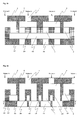
- Fig. 9 and Fig. 10 are a partially enlarged plan view of the composite spinneret of Patent Document 5
- Fig. 23 is a partially enlarged plan view of the composite spinneret of Patent Document 8.
- the lowermost layer distribution plate 5 described in Fig. 9 and Fig. 10 is different in name from an upper layer plate 29 in Fig. 23 ; however, these play the same role.
- the pattern in Patent Document 5 and Patent Document 8 is a pattern in which three or four sea component discharge holes 4 are equally disposed around the island component discharge hole 1 (zigzag alignment), and it appears that islands-in-the-sea composite fibers in which the island component form is polygonal can be obtained at a glance.
- the island component polymer streams may join with one another.
- the problem may not be solved in some cases even when changing spinning conditions such as discharge amounts and a ratio between discharge amounts of the respective component polymers, and in the worst case, the production may become impossible and the productivity may be deteriorate in some cases if not changing the composite spinneret.
- Patent Document 2 discloses a composite spinneret as shown in Fig. 13.
- Fig. 13 is a schematic sectional view of the composite spinneret of Patent Document 2.
- a reference numeral 10 indicates a discharge plate
- a reference numeral 11 indicates a discharge introduction hole
- a reference numeral 43 indicates a multilayer plate
- a reference numeral 44 indicates a dividing plate
- a reference numeral 45 indicates an arrangement plate, respectively.
- the composite spinneret is configured by laminating the multilayer plate 43, the dividing plate 44, the arrangement plate 45 and the discharge plate 10 in turn, a sea component polymer and an island component polymer which are flown from an upstream side are layered, the layered polymer is partially divided, aligned in another order, and divided again to be changed to a sea-island composite stream having many island components, and ultimately the sea-island composite stream is discharge from the discharge introduction hole 11, and thereby, islands-in-the-sea composite fiber can be manufactured.
- ultrafine fibers obtained by dissolving the island component are not changed in an islands-in-the-sea structure even in long term spinning, a shape of island is circular and a thickness thereof is uniform, and a fiber diameter can reach the nano-order size.
- the shape of island of ultrafine fibers obtained by using the composite spinneret of Patent Document 2 is limited to a circular shape or an elliptical shape similar to the circular shape, the ultrafine fibers having a complicated shape such as a polygonal shape of island may not be obtained in some cases.
- Patent Document 2 since a variation of the actual number of islands to the theoretical number of islands ((maximum number of islands - minimum number of islands)/average number of islands) x 100 [%]) is in a range of ⁇ 20%, the number of islands may not be controlled with high precision in some cases.
- types of the sea component polymers which can be used are limited to polyethylene and polystyrene, and a variety of polymers (polymers having different structures such as polyester, polyamide, polyphenylenesulfide, and polyolefin) may not be used in some cases.
- Patent Documents 3 and Document 7 disclose composite spinnerets each is generally known as a pipe system spinneret which manufactures islands-in-the-sea fibers.
- Fig. 14 is a schematic sectional view of the composite spinneret of Patent Documents 3 and 7.
- Fig. 14 is a schematic sectional view of the composite spinneret of Patent Documents 3 and 7.
- a reference numeral 30 indicates a pipe
- a reference numeral 31 indicates a sea component polymer introduction flow path
- a reference numeral 32 indicates an island component polymer introduction flow path
- a reference numeral 33 indicates an upper spinneret plate
- a reference numeral 34 indicates a middle spinneret plate
- a reference numeral 35 indicates a lower spinneret plate
- a reference numeral 40 indicates a distribution chamber for a sea component polymer
- a reference numeral 41 indicates a pipe insertion hole
- a reference numeral 42 indicates a spinneret discharge hole, respectively.
- the spinneret of Patent Document 3 is generally known as a pipe system spinneret, and it is composed of the upper spinneret plate 33 provided with the sea component polymer introduction flow paths 31, the island component polymer introduction flow paths 32 and the pipes 30; the middle spinneret plate 34 provided with the pipe insertion hole 41 with a diameter equal to or larger than an outer diameter of the pipe 30; and the lower spinneret plate 35 provided with the spinneret discharge holes 42.
- the sea component polymer of an easy-to-elute component is guided from the sea component polymer introduction flow paths 31 to the distribution chamber 40 for a sea component polymer to fill the outer circumference of the pipe 30, and on the other hand, the island component polymer of a hard-to-elute component is guided from the island component polymer introduction flow paths 32 to the pipes 30, and discharged from the pipe 30, and thereby, polymers of both components join with each other to form a sea-island composite cross section, and then a composite polymer is discharged from the spinneret discharge hole 42 through the pipe insertion hole 41, and thereby, islands-in-the-sea composite fibers can be manufactured.
- the pipe system spinneret of Patent Document 3 has a large problem that since a pipe thickness is added for manufacturing an island, an area per a pipe is increased. Further, since the pipe 30 is press-fitted in the upper spinneret plate 33 and fixed to the upper spinneret plate 33 by welding for manufacturing a spinneret, a welding clearance is required, and since a hole for insertion of the pipe 30 is disposed, a space between pipes cannot be narrowed because of a problem of strength. Accordingly, the pipes 30 may not be arranged in a close-packed state per a unit area and the hole packing density may not be increased, and thus it may be difficult to manufacture ultrafine fibers with a fiber diameter of nano-order size in some cases.
- the resulting shape of island is limited to a circular shape or an elliptical shape similar to the circular shape, the islands-in-the-sea composite fibers having a complicated shape such as a polygonal shape of island may not be obtained in some cases. Since this spinneret has a low degree of freedom for an arrangement of the pipes 30 and a controllable fiber cross section form is limited, it may be difficult to manufacture fibers in which complicated cross sections are layered in some cases.
- the sea component polymer introduction flow path 31 is disposed at the outer circumference of a pipe group where the pipes 30 are arranged in a close-packed state, it is difficult to supply an adequate sea component polymer to the center of the pipe group, and particularly the island component polymer streams discharged from the pipes 30 at the center of the pipe group may join with one another in some cases.
- the above-mentioned problem becomes more remarkable.
- the spinneret has a problem that the spinneret has a very complicated structure and facility cost is expensive since for example, in order to dispose the sea component polymer introduction flow path 31 in the group of pipes, it is necessary to dispose the sea component polymer introduction flow path 31 by bending the pipe 30 on the way.
- Fig. 18 is a schematic sectional view of the composite spinneret of Patent Document 6.
- a reference numeral 25 indicates a discharge hole
- a reference numeral 55 indicates an upper plate
- a reference numeral 56 indicates a projection, respectively.
- Patent Document 6 describes that the distribution of a polymer can be improved by having the projections 56 around the discharge hole 25 and the island component discharge hole 1 in order to distribute the sea component polymer and the island component polymer uniformly, and narrowing a gap between a bottom surface of the upper spinneret plate 33 and a top surface of the projection 56 formed around the discharge hole 25, and a gap between a bottom surface of the upper plate 29 and a top surface of the projection 56 formed around the island component discharge hole 1 to increase a pressure loss.
- Fig. 15 is a schematic sectional view of the composite spinneret of Patent Document 4.
- a reference numeral 27 indicates a radial groove and a reference numeral 28 indicates a groove on a concentric circle.
- Patent Document 4 describes that by forming the radial grooves 27 around the island component discharge hole 1 and the grooves 28 on a concentric circle around the discharge hole 25, islands-in-the-sea composite fibers can be attained, in which the distribution of the sea component polymer is improved and island component streams are prevented from joining with one another even when a ratio of the sea component polymer is low.
- a composite spinneret which can prevent the island component polymer streams from joining with one another while increasing the hole packing density of the discharge holes for the island component polymer, and thereby, can form various fiber cross sections, particularly heteromorphic cross sections, with high accuracy while maintaining high dimensional stability of the cross section, and a method of manufacturing composite fibers in which melt spinning is performed by a composite spinning machine using the composite spinneret.
- a composite spinneret for discharging composite polymer streams composed of an island component polymer and a sea component polymer, which is composed of one or more distribution plates in which distribution holes and distribution grooves for distributing the polymer components are formed; and a lowermost layer distribution plate positioned to the downstream side of the distribution plate in the direction of the polymer spinning path, and having formed therein a plurality of island component discharge holes and a plurality of sea component discharge holes, wherein the sea component discharge holes are arranged on a virtual circular line C1 with a radius R1 centered on the island component discharge hole, the sea component discharge holes are arranged on a virtual circular line C2 with a radius R2 centered on the island component discharge hole, and the island component discharge holes are arranged on a virtual circular line C4 with a radius R4 centered on the island component discharge hole, and R1, R
- the composite spinneret wherein with respect to a plurality of polymer flow through paths composed of the distribution hole and the distribution groove within the distribution plate, a diameter of the distribution hole in a path in which a length of the polymer flow through path from an upper end of the distribution plate to the lowermost layer distribution plate is comparatively long is larger than a diameter of the distribution hole in a path in which a length of the polymer flow through path is comparatively short.
- the composite spinneret wherein at least a part of the sea component discharge hole is present in a region surrounded with two lines commonly circumscribing the neighboring two island component discharge holes.
- the composite spinneret wherein at least a part of each of at least two of the sea component discharge holes is present in a region surrounded with two lines commonly circumscribing the neighboring two island component discharge holes, and the two sea component discharge holes are located across a line segment connecting centers of the two island component discharge holes.
- the composite spinneret wherein a thickness of a distribution plate having a distribution groove configured therein at the upstream side in the direction of the polymer spinning path is larger than that at the downstream side.
- the composite spinneret wherein a diameter DMIN of a minimum hole formed in the distribution plate or the lowermost layer distribution plate, and a thickness BT of a plate in which the minimum hole is formed satisfy the following expression: BT / DMIN ⁇ 2 wherein DMIN represents a diameter (mm) of a minimum hole formed in the distribution plate or the lowermost layer distribution plate, and BT represents a thickness (mm) of the distribution plate or the lowermost layer distribution plate in which the minimum hole is formed.
- the composite spinneret wherein a thickness of the distribution plate or the lowermost layer distribution plate is 0.1 to 0.5 mm.
- the composite spinneret wherein a hole packing density of the island component discharge hole is 0.5 hole/mm 2 or more.
- melt spinning is performed by a composite spinning machine using the above-mentioned composite spinneret in which flow-path pressure losses at the respective flow paths from the distribution plate to the island component discharge holes of the lowermost layer distribution plate are the same, and flow-path pressure losses at the respective flow paths from the distribution plate to the sea component discharge holes of the lowermost layer distribution plate are the same.
- melt spinning is performed at a ratio of the island component polymer of 50% or more by a composite spinning machine using the composite spinneret.
- the distribution hole refers to a hole which is formed by combining a plurality of distribution plates into one and plays a role of distributing a polymer in the direction of the polymer spinning path.
- the distribution groove refers to a groove which is formed by combining a plurality of distribution plates into one and plays a role of distributing a polymer in the direction perpendicular to the direction of the polymer spinning path.
- the distribution groove may be a long and thin hole (slit), or a long and thin groove may be cut.
- the direction of the polymer spinning path refers to a main direction in which the respective polymer components flow from a metering plate to a spinneret discharge hole of a discharge plate.
- the direction perpendicular to the direction of the polymer spinning path refers a direction perpendicular to the main direction in which the respective polymer components flow from a metering plate to a spinneret discharge hole of a discharge plate.
- the virtual circular line C1 with a radius R1 refers to a virtual circular line C1 in which a center distance between an island component discharge hole as a reference and a sea component discharge hole closest to the island component discharge hole as a reference is a radius R1.
- the virtual circular line C2 with a radius R2 refers to a virtual circular line C2 in which a center distance between an island component discharge hole as a reference and a sea component discharge hole second closest to the island component discharge hole as a reference is a radius R2.
- the virtual circular line C4 with a radius R4" refers to a virtual circular line C4 in which a center distance between an island component discharge hole as a reference and an island component discharge hole closest to the island component discharge hole as a reference is a radius R4.
- the center angle refers to an angle at which two line segments connecting the center of the island component discharge hole as a reference and centers of two sea component discharge holes adjacent to each other in a circumferential direction, which are arranged on the virtual circular line C1, or C2 intersect, or an angle at which two line segments connecting the center of the island component discharge hole as a reference and centers of two island component discharge holes adjacent to each other in a circumferential direction, which are arranged on the virtual circular line C4 intersect.
- the phase angle refers to an angle at which a line segment connecting the center of the island component discharge hole as a reference and the center of the sea component discharge hole arranged on the virtual circular line C1, and a line segment connecting the center of the island component discharge hole as a reference and the center of the sea component discharge hole arranged on the virtual circular line C2 intersect, or an angle at which a line segment connecting the center of the island component discharge hole as a reference and the center of the sea component discharge hole arranged on the virtual circular line C1, and a line segment connecting the center of the island component discharge hole as a reference and the center of the sea component discharge hole arranged on the virtual circular line C2 intersect.
- the polymer flow through path refers to a path formed by communicating the distribution hole formed within the distribution plate with the distribution groove formed within the distribution plate.
- the hole packing density refers to a value determined by dividing the number of island component discharge holes for discharging an island component polymer by a cross section area of the discharge introduction hole.
- the hole packing density is larger, a composite fiber is obtained which is composed of more island component polymers.
- the island-component polymer is uniformly distributed and the island component polymer streams are prevented from joining with one another while increasing the hole packing density of the discharge holes for the island component polymer, and thereby, various fiber cross sections, particularly heteromorphic cross sections, are formed with high accuracy while maintaining high dimensional stability of the cross section.
- FIG. 5 is a schematic sectional view of a composite spinneret used in an embodiment of the present invention
- Fig. 7 is a view taken in the direction of arrows X-X in Fig. 5
- Fig. 1 is a partially enlarged plan view of Fig. 7
- Figs. 2 , 3, 4 and 16 are respectively a partially enlarged plan view of a lowermost layer distribution plate used in another embodiment of the present invention
- Fig. 6 is a schematic sectional view of a composite spinneret, and surroundings of a spin pack and a cooling apparatus, which are used in an embodiment of the present invention
- 17 , 20 , 21, 22 , 31 and 38 are respectively a schematic partially sectional view of a distribution plate and a lowermost layer distribution plate used in an embodiment of the present invention.
- these are conceptual drawings for correctly expressing the essential points of the present invention and are simplified, and the composite spinneret of the present invention is not limited to these, and the number of holes and grooves, and a dimensional ratio of holes and grooves may be changed according to the embodiment.
- a composite spinneret 18 used in an embodiment of the present invention is fitted in a spin pack 15 and fixed in a spin block 16, and a cooling apparatus 17 is configured immediately below the composite spinneret 18.
- Two types or more of polymers introduced into the composite spinneret 18 respectively pass through a metering plate 9, a distribution plate 6 and a lowermost layer distribution plate 5, and are discharged from a spinneret discharge hole 42 of a discharge plate 10 and then cooled by an air stream blown out from the cooling apparatus 17 and provided with a spinning oil, and then the polymers are taken up as islands-in-the-sea composite fibers.
- a metering plate 9 As shown in Fig. 6 , a composite spinneret 18 used in an embodiment of the present invention is fitted in a spin pack 15 and fixed in a spin block 16, and a cooling apparatus 17 is configured immediately below the composite spinneret 18.
- Two types or more of polymers introduced into the composite spinneret 18 respectively pass through a metering plate 9, a
- the annular cooling apparatus 17 which blows an air stream annually-inwardly is employed; however, a cooling apparatus which blows an air stream from one direction may be used.
- a cooling apparatus which blows an air stream from one direction may be used.
- a flow path or the like used in the existing spin pack 15 may be used, and the member does not need to be exclusive.
- the composite spinneret 18 used in an embodiment of the present invention is configured by laminating the metering plate 9, at least one distribution plate 6, the lowermost layer distribution plate 5 and the discharge plate 10 in turn, and particularly the distribution plate 6 and the lowermost layer distribution plate 5 are preferably composed of a thin plate.
- the metering plate 9 and the distribution plate 6, and the lowermost layer distribution plate 5 and the discharge plate 10 are positioned so as to be aligned with a center position (core) of the spin pack 18 by a locating pin, laminated, and then may be fixed by a screw or bolt, or may be metal-joined (diffusion-bonded) by thermocompression bonding.
- the distribution plates 6, and the distribution plate 6 and the lowermost layer distribution plate 5 are preferably metal-joined (diffusion-bonded) with each other by thermocompression bonding since a thin plate is used for these plates.
- a thickness of the thin plate is preferably in a range of 0.01 to 1 mm, and further suitably 0.1 to 0.5 mm.
- the thickness of the thin plate is small, there are advantages that hole diameters, groove widths and hole pitches/groove pitches of processable holes/grooves can be reduced and hence the hole packing density can be increased.
- the hole packing density can be more increased.
- DMIN is taken as a groove width, and when the DMIN and a plate thickness BT of the distribution plate 6 satisfy the expression (3), the hole packing density can be more increased as with the above-mentioned case.
- a type of a polymer capable of being used may be limited in some cases (with a high viscous polymer, a pressure loss is increased and bending occurs). In this case, a whole thickness may be increased by laminating and metal-joining a plurality of thin plates to improve the strength. Further, the strength per a plate is improved by increasing the thickness of the thin plate, and therefore there is an advantage of increasing a type of polymer capable of being used.
- a thickness of the distribution plate having the great number of holes may be reduced, and a thickness of the distribution plate having the smaller number of holes may be increased.
- polymers of the respective components supplied from the metering plate 9 pass through the distribution groove 8 and a distribution hole 7 of the distribution plate 6 formed by laminating at least one plate, and then are discharged from the island component discharge hole 1 for discharging an island component polymer and a sea component discharge hole 4 for discharging a sea component polymer of the lowermost layer distribution plate 5, and thereby, the polymers of the respective components join with each other to form a composite polymer stream. Thereafter, the composite polymer stream passes through a discharge introduction hole 11 and a contracting hole 12 of the discharge plate 10, and is discharged from the spinneret discharge hole 42.
- all of diameters of the island component discharge holes 1 disposed in the lowermost layer distribution plate 5 are preferably the same, and all of diameters of the sea component discharge holes 4 disposed in the lowermost layer distribution plate 5 are preferably the same.
- the diameters of the island component discharge hole 1 and the sea component discharge hole 4 are preferably in a range of 0.03 to 0.8 mm, and further suitably in a range of 0.05 to 0.5 mm.
- the island component polymer streams can be prevented from joining with one another while increasing the hole packing density of the composite spinneret 18, and various fiber cross sections, particularly heteromorphic cross sections, can be formed with high accuracy.
- the island component discharge holes 1 need to be close to one another as much as possible, and in this case, island-component polymer streams join with one another between neighboring island component discharge holes. For example as shown in Fig.
- joining of the island component polymer streams in the case where a cross section of the island component has a circular shape takes place mainly on a line connecting centers of neighboring island component discharge holes 1; however, joining of the island component polymer streams in the case where a cross section of the island component is a heteromorphic cross section having a plurality of edge (corner) portions takes place not only on the line connecting gravity centers of the island component discharge holes 1, but also between neighboring edge portions.
- the sea component discharge holes 4 are arranged on the virtual circular line C1 with a radius R1, centered on the island component discharge hole 1, the sea component discharge holes 4 are arranged on the virtual circular line C2 with a radius R2, centered on the island component discharge hole 1, and the island component discharge holes 1 are arranged on the virtual circular line C4 with a radius R4, centered on the island component discharge hole 1, and these discharge holes are arranged to satisfy the expression (1) and according to any one of the conditions (2) (a) to (2)(d).
- the conditions (2) (a) and (2)(b) indicate an arrangement pattern of the island component discharge holes 1 and the sea component discharge holes 4 by which the island component has a triangle cross section
- the condition (2)(c) indicates an arrangement pattern thereof by which the island component has a hexagonal cross section
- the condition (2) (d) indicates an arrangement pattern thereof by which the island component has a tetragonal cross section.
- both the island component polymer and the sea component polymer are discharged all together toward the discharge introduction hole 11 located the downstream side of the lowermost layer distribution plate 5, flow in the direction of the polymer spinning path while expanding their width in the direction perpendicular to the direction of the polymer spinning path, and join with one another to form a composite polymer.
- an important role of the sea component discharge holes 4a on the virtual circular line C1 is to form a heteromorphic cross section of the island component. This partially suppresses the expansion of width of the'island-component polymer discharged from the island component discharge hole 1 as a reference, that is, the expansion of width of the island-component polymer is suppressed from three point by arranging three sea component discharge holes 4a equally at a center angle of 120 degrees in order to form a triangle cross section of the island-component polymer.
- the sea component discharge holes 4b on the virtual circular line C2 are arranged equally at a center angle of 120 degrees with a phase angle between the discharge hole on the C1 and the discharge hole on the C2 being 60 degrees, the island-component polymer flown out from between the sea component discharge holes 4a is suppressed by the sea component polymer discharged from the sea component discharge hole 4b.
- the sea component discharge holes 4a and the sea component discharge holes 4b have a phase difference and are respectively arranged on the virtual circular line C1 and the virtual circular line C2 having different radii
- the sea component discharge holes 4a arranged on an inner circumference side has a role of forming a side of the triangle cross section
- the sea component discharge holes 4b arranged on an outer circumference side has a role of forming an edge (corner) portion of the triangle cross section.
- these discharge holes have a role of suppressing joining of the island-component polymer stream discharged from the island component discharge hole 1 as a reference to the island-component polymer stream discharged from the island component discharge hole 1a on the virtual circular line C4.
- the radius R4 of the virtual circular line C4 may be reduced to bring the island component discharge hole 1 as a reference closer to the island component discharge hole 1a, and in this case, the present inventors have found that the island-component polymer streams discharged from respective island component discharge holes expand their widths and there is a limiting distance at which the island-component polymer streams join with one another.
- the hole arrangement whereby the island-component polymer streams can be prevented from joining with one another while forming a space to adequately expand the island-component polymer discharged from the island component discharge hole 1 in a space sandwiched between the virtual circular line C1 and the virtual circular line C2 is a key. That is, in order to achieve this, the radius R4, which is a center distance between the island component discharge hole 1 as a reference and the island component discharge hole 1a adjacent to the island component discharge hole 1 as a reference, may be determined to satisfy the expression (1).
- this arrangement is characterized in that the great number of islands can be arranged to increase the island packing density; however, a ratio of the island-component polymer may not be increased to 50% or more in some cases, this arrangement is suitable for achieving composite fibers with fiber diameter of nano-order size such as nano-fibers.
- other arrangement patterns in which the island component has a triangle cross section include the arrangement according to the condition (2)(b).
- three sea component discharge holes 4 are arranged equally at a center angle of 120 degrees on a virtual circular line C1 around the island component discharge hole 1 as a reference, and three island component discharge holes 1 are arranged equally at a center angle of 120 degrees on an outer virtual circular line C4 of the virtual circular line C1 with a phase angle between the discharge hole on the C1 and the discharge hole on the C4 being 0 degree, and three sea component discharge holes 4 are arranged equally at a center angle of 120 degrees on an outer virtual circular line C2 of the virtual circular line C1 with a phase angle between the discharge hole on the C1 and the discharge hole on the C2 being 60 degrees.
- a ratio of the island-component polymer can be large, and fibers can be obtained, in which the island component polymer streams do not join with one another and the island component has a uniform triangle cross section even at an island ratio as high as 70% or more.
- an arrangement pattern in which the island component has a hexagonal cross section includes the arrangement according to the condition (2)(c).
- the arrangement according to the condition (2)(c) six sea component discharge holes 4 are arranged equally at a center angle of 60 degrees on a virtual circular line C1 around the island component discharge hole 1 as a reference, and six island component discharge holes 1 are arranged equally at a center angle of 60 degrees on an outer virtual circular line C4 of the virtual circular line C1 with a phase angle between the discharge hole on the C1 and the discharge hole on the C4 being 30 degree, and six sea component discharge holes 4 are arranged equally at a center angle of 60 degrees on an outer virtual circular line C2 of the virtual circular line C1 with a phase angle between the discharge hole on the C1 and the discharge hole on the C2 being 30 degrees.
- the hole packing density can be large and a ratio of the island-component polymer can be large, and fibers can be obtained, in which the island component polymer streams do not join with one another and the island component has a uniform hexagonal cross section even at an island ratio as high as 70% or more.
- an arrangement pattern in which the island component has a tetragonal cross section includes the arrangement according to the condition (2)(d).
- four sea component discharge holes 4 are arranged equally at a center angle of 90 degrees on a virtual circular line C1 around the island component discharge hole 1 as a reference, and four island component discharge holes 1 are arranged equally at a center angle of 90 degrees on an outer virtual circular line C4 of the virtual circular line C1 with a phase angle between the discharge hole on the C1 and the discharge hole on the C4 being 0 degree, and eight sea component discharge holes 4 are arranged on an outer virtual circular line C2 of the virtual circular line C1 with a phase angle between the discharge hole on the C1 and the discharge hole on the C2 being 22.5 degrees.
- the hole packing density can be large and a ratio of the island-component polymer can be large, and fibers in which the island component has a uniform tetragonal cross section can be obtained even at an island ratio as high as 70% or more.
- a plurality of the distribution plates 6 are provided, and the plural laminated distribution plates 6 are configured in such a way that the number of the distribution holes 7 formed in the distribution plate 6 increases toward the downstream side in the direction of the polymer spinning path, and the distribution groove 8 is formed so as to communicate the distribution hole 7 positioned to the upstream side in the direction of the polymer spinning path with the distribution hole 7 positioned to the downstream side in the direction of the polymer spinning path by alternately laminating a distribution plate 6 in which a distribution hole 7 guiding a polymer in the direction of the polymer spinning path is formed and a distribution plate 6 in which the distribution groove 8 guiding a polymer in the direction perpendicular to the direction of the polymer spinning path is formed.
- the distribution hole 7 is formed on one surface of one distribution plate 6 and the distribution groove 8 is formed on the other surface of one distribution plate 6, and the distribution hole 7 is communicated with the distribution groove 8.
- the distribution hole 7 may be formed through the distribution plate 6, or the distribution groove 8 may be formed through the distribution plate 7.
- a flow through path of a polymer of a sequential branch system in which the distribution groove 8 in communication with a position at the downstream side in the direction of the polymer spinning path is formed per one distribution hole 7 and a plurality (two in Fig. 17 ) of the distribution holes 7 in communication with an end of the distribution groove 8 are formed.
- the lengths of paths from the distribution hole 7 or the distribution groove 8 of the distribution plate 6 positioned at the highest end in the direction of the polymer spinning path to the island component discharge holes 1 of the lowermost layer distribution plate 5 are equal.
- the flow through path of a polymer has a structure in which hole diameters of the distribution holes 7, and widths, depths and lengths of the distribution grooves 8 are equalized in each distribution plate 6 of the laminated plural distribution plates 6.
- a hole diameter of the distribution hole 7 or a width or depth of the distribution groove 8 is increased sequentially to suppress an increase in the flow-path pressure loss.
- the flow through path of a polymer of a sequential branch system of two-way branch is suitable, in which one distribution groove 8 is communicated with two distribution holes 7 at the downstream side in the direction of the polymer spinning path; however, the sequential branch system is not limited to this.
- the distribution groove 8 is communicated with two or more distribution holes 7 (the case of a flow path of a sequential branch system of two-way or more branch)
- this structure has an advantage of eliminating abnormal retention of a polymer, and uniformly distributing and precisely controlling a polymer.
- examples of other structure in which flow-path pressure losses of the flow through paths of the respective polymers are equalized, include structures with respect to a plurality of polymer flow through paths composed of the distribution hole 7 and the distribution groove 8 within the distribution plate 6, a diameter of the distribution hole 6 in a path in which a length of the polymer flow through path from an upper end of the distribution plate 6 to the lowermost layer distribution plate 5 of the distribution plate 6 is comparatively long is larger than a diameter of the distribution hole 6 in a path in which a length of the polymer flow through path is comparatively short, and thereby, it becomes possible to equalize flow-path pressure losses.
- examples of other structure in which flow-path pressure losses of the flow through paths of the respective polymers are equalized, include structures in which a diameter of the island component discharge hole 1 of the lowermost layer distribution plate 5 is adjusted so that flow-path pressure losses are equalized in the respective flow paths of the distribution plate 6 on the upstream side thereof. Specifically, it becomes possible to equalize flow-path pressure losses by increasing a diameter of the island component discharge hole 1 in communication with a flow path having a large flow-path pressure loss, and decreasing a diameter of the island component discharge hole 1 in communication with a flow path having a smaller flow-path pressure loss on the upstream side.
- one distribution groove 8 is communicated with a plurality of the distribution holes 7 on the downstream side in the direction of the polymer spinning path, and communicated with a plurality of the distribution holes 7 on the upstream side in the direction of the polymer spinning path, it becomes possible to equalize flow-path pressure losses by employing, as the structure of equalizing flow-path pressure losses of the flow through paths of the respective polymers, a structure in which a diameter of the distribution hole 7 positioned at an end part of the distribution groove 8 is increased as compared with a central part in order to equalize flow rates of polymers passing through the distribution hole 7 in communication with the central part and the distribution hole 7 in communication with the end part of the distribution groove 8.
- the distribution hole 7 disposed in the distribution plate 6 distributes a polymer mainly in the direction of the polymer spinning path
- the distribution groove 8 distributes a polymer mainly in the direction perpendicular to the direction of the polymer spinning path
- the polymer can be freely and easily distributed in the direction of a fiber cross section, and by using this, the sea component discharge holes 4 can be arranged in an extremely narrow region between neighboring island component discharge holes 1.
- the distribution holes 7 and the distribution grooves 8 are preferably disposed in the distribution plate 6 immediately above the lowermost layer distribution plate 5.
- the distribution hole 7 is communicated with the island component discharge hole 1
- the distribution groove 8 is communicated with the sea component discharge hole 4.
- the distribution groove 8 can be arranged at a position closer to the distribution hole 7, and the sea component discharge hole 4 communicated with the distribution groove 8 can be arranged in a state of being closer to the island component discharge hole 1, and the hole packing density can be increased.
- the distribution plate 6 immediately above the lowermost layer distribution plate 5 when the downstream side of the distribution groove 8 in the direction of the polymer spinning path is communicated with the distribution hole 7 as shown in Fig.
- the distribution plate 6 and the lowermost layer distribution plate 5 of the present invention have a laminate structure of thin plates.
- a shape of the composite spinneret 18 in the present invention is not limited to a circular shape, and may be a tetragonal shape or a polygonal shape. Further, an array of the spinneret discharge hole 42 in the composite spinneret 18 may be appropriately determined according to the number of the islands-in-the-sea composite fibers, the number of line of yarn, and the cooling apparatus 17. With respect to the cooling apparatus 17, for an annular cooling apparatus, the spinneret discharge holes 42 may be arrayed in an annular form over one column or plural columns, and for a cooling apparatus of one way, the spinneret discharge holes 42 may be arrayed in zigzag alignment.
- a cross section of the spinneret discharge hole 42 in the direction perpendicular to the direction of the polymer spinning path is not limited to a circular shape, and may be a cross section other than the circular shape or a hollow cross section. However, a cross section other than the circular shape is employed, a length of the spinneret discharge hole 42 is preferably lengthened in order to ensure the polymer metering capability.
- a cross section in the direction perpendicular to the direction of the polymer spinning path is not limited to a circular shape, and may be a cross section other than the circular shape or a hollow cross section.
- all shapes of the island component discharge holes 1 disposed in the lowermost layer distribution plate 5 are preferably the same.
- the island component discharge hole 1 is previously shaped to a similar shape, and therefore, fibers with a heteromorphic cross section are easily obtained.
- the island component discharge hole 1 has a cross section other than a circular shape
- a cross section in the direction perpendicular to the direction of the polymer spinning path is not limited to a circular shape, and may be a cross section shape other than the circular shape.
- all shapes of the sea component discharge holes 4 disposed in the lowermost layer distribution plate 5 are preferably the same.
- the discharge introduction hole 11 in the present invention can mitigate a difference in flow velocities immediately after the island component polymer stream joins with the sea component polymer stream by providing a certain entrance section from a bottom surface of the lowermost layer distribution plate 5 in the direction of the polymer spinning path to stabilize a composite polymer stream.
- a diameter of the discharge introduction hole 11 is preferably configured to be larger than an outer diameter of a virtual circle 52 of a group of discharge holes of the island component discharge holes 1 and the sea component discharge holes 4 disposed in the lowermost layer distribution plate 5, and is preferably configured in such a way that a ratio of a cross section area of the virtual circle 52 to a cross section area of the discharge introduction hole 11 is as small as possible.
- the contracting hole 12 in the present invention it is possible to inhibit unstable phenomena such as draw resonance of the composite polymer stream and supply the composite polymer stream stably by setting a taper angle ⁇ of a flow path from the discharge introduction hole 11 to the spinneret discharge hole 42 to a range of 50 to 90°.
- a taper angle ⁇ is less than 50°, the unstable phenomena of the composite polymer stream can be inhibited; however, the composite spinneret 18 itself grows in size, and when the taper angle ⁇ is more than 90°, the unstable phenomena of the composite polymer stream may become more remarkable.
- the island component discharge hole 1, the sea component discharge hole 4 and the distribution hole 7 in the present invention preferably have a hole cross section area which is constant in the direction of the polymer spinning path; however, the hole cross section area may gradually decrease or may increase, or may gradually decrease and increase.
- the reason for this is that in the distribution plate 6 and the lowermost layer distribution plate 5 in the present invention, since hole processing is mainly performed by using etching processing, the hole cross section area may not become constant in the direction of the polymer spinning path in some cases in processing minute holes, and in this case, processing conditions and the like may be appropriately made to be proper.
- the number of the lowermost layer distribution plates 5 in the present invention may be one; however, a plurality of the lowermost layer distribution plates 5 may be laminated. In case that one lowermost layer distribution plate 5 cannot achieve the polymer metering capability of the island component discharge holes 1 and the sea component discharge holes 4, and a fiber form varies with time, the metering capability of a polymer can be ensured by laminating a plurality of the lowermost layer distribution plates 5.
- the distribution hole 7 may be disposed to the upstream side of the distribution plate 6, and the distribution groove 8 (downstream side) may be disposed in communication with the distribution hole 7, or the distribution groove 8 may be arranged to the upstream side of the distribution plate 6, and the distribution hole 7 (downstream side) may be disposed in communication with the distribution groove 8.
- the polymer can be distributed by communicating the distribution hole 7 with the distribution groove 8 and repeating the communication once or more.
- a sequential branch system is most preferred; however, as shown in Fig. 38 , a slit system may be employed, in which one distribution groove 8 is configured for a plurality of the distribution holes 7, or a plurality of the distribution grooves 8 are configured for a plurality of the distribution holes 7, or a combined method which is a combination of the sequential branch system and the slit system may be employed.
- polymers of other components employ the same distribution method as described above; however, for the sake of simplicity, only the case of a polymer of one component will be described.
- the sequential branch system has, as described above, an advantage of eliminating abnormal retention of a polymer, and uniformly distributing and precisely controlling a polymer by disposing the distribution hole 7 at an end part of the distribution groove 8.
- the distribution hole 7 is clogged with a polymer in production, the polymer is not distributed to the downstream side, and consequently fibers with a desired composite cross section may not be obtained in some cases.
- the slit system is highly responsible for the problems of clogging in the hole or groove since a plurality of the distribution holes 7 are formed for one distribution groove 8, and the slit system has an advantage of keeping manufacturing costs of the composite spinneret 18 low since one distribution plate 6 can distribute many polymers in the direction perpendicular to the direction of the polymer spinning path to reduce the number of the distribution plate 6.
- abnormal retention of a polymer easily occurs, and this method may be inferior in precise control of polymer distribution to the sequential branch system in some cases.
- a combined method in which the slit system is configured at the upstream side (metering plate 9 side), and the sequential branch system is configured at the downstream side (lowermost layer distribution plate 5 side), and defective polymer distribution due to clogging of the hole or groove is eliminated at the upstream side and metering capability of a polymer is enhanced at the downstream side to distribute the polymer uniformly.
- a method of enhancing metering capability of a polymer in which in the case where a polymer of one component passes through the distribution hole 7 (flow-in side), the distribution groove 8 and the distribution hole 7 (flow-out side), a diameter of a hole close to the distribution hole 7 on the flow-in side is smaller and a diameter of a hole remote to the distribution hole 7 on the flow-in side is larger. That is, a hole diameter is preferably adjusted so as to equalize a flow-path pressure loss of the distribution hole 7 (flow-out side) close to the distribution hole 7 on the flow-in side and a flow-path pressure loss of the distribution hole 7 (flow-out side) remote to the distribution hole 7 on the flow-in side.
- adjustment of the flow-path pressure loss may be performed by adjusting a groove width of the flow path groove 8. Further, as described above, in order to equalize flow-path pressure losses at all the distribution plates 6, dimensions of the distribution hole 7 and the distribution groove 8 may be adjusted; however, diameters of only distribution holes 7 of the distribution plate 6 in contact with the lowermost layer distribution plate 5 may be adjusted so as to equalize all flow-path pressure losses on the upstream side thereof.
- a diameter of the distribution hole 7, a groove width and a groove depth of the distribution groove 8 are increased, and it is particularly preferred that at the upstream side (metering plate 9 side) in the direction of the polymer spinning path, a thickness of the distribution plate 6 constituting the distribution groove 8 is increased, and a groove depth and a groove width of the distribution groove 8 is increased, and a diameter of the distribution hole 7 is increased.
- the distribution groove 8 and the distribution hole 7 in the distribution plate 6 may be appropriately arranged according to desired fiber cross section form, and the method is not particularly limited to the above method.
- the composite spinneret 18 of the present invention may be used in a publicly known composite spinning machine.
- a spinning temperature a temperature at which principally a polymer with a high melting point or high viscosity of two types or more of polymers exhibits flowability is selected.
- a melting point of the polymer is a standard, and the spinning temperature may be set to melting point + 60°C or lower.
- a spinning velocity varies depending on the properties of the polymer and an object of the composite fibers, and can be set to about 500 to 6000 m/min. Particularly, when high mechanical properties are required in industrial material applications, preferably, a high molecular weight polymer is used and spun at a spinning velocity of 500 to 2000 m/min, and thereafter it is stretched at a high ratio.
- a temperature at which a polymer can be softened such as a glass transition temperature of the polymer is used as a standard, and a pre-heating temperature is appropriately set.
- a temperature is preferably set at which fluctuations of a yarn route due to self-extension of a fiber does not occur in a pre-heating process.
- the pre-heating temperature is generally set to about 80 to 95°C.
- a discharge velocity ratio between polymers of the respective components discharged from the island component discharge holes 1 and the sea component discharge holes 4 of the present invention is preferably controlled by a discharge amount, a hole diameter and the number of holes (the discharge velocity refers to a value obtained by dividing a discharge flow rate by a cross section area of the island component discharge hole 1 or the sea component discharge hole 4).
- a ratio thereof (Va/Vb or Vb/Va) is preferably in a range of 0.05 to 20, and more preferably in a range of 0.1 to 10, and when the ratio is in this range, since a polymer discharged from the lowermost layer distribution plate 5, as a laminar flow, is guided to the contracting hole 12 through the discharge introduction hole 11, a cross section form is significantly stabilized and can be maintained accurately.
- a melt viscosity ratio of the polymer used in the present invention is less than 2.0, a composite polymer stream can be stably formed.
- the melt viscosity ratio is 2.0 or more, a composite polymer stream becomes unstable when the island-component polymer joins with the sea component polymer, and uneven thickness of the resulting fiber cross section may occur in a running direction in some cases.
- etching processing is a processing method in which a thin plate is etched (dissolved/chemically cut) with use of a chemical reaction/corrosive action by chemicals such as an etching solution, and in this method, an objective processing shape is subjected to anti-corrosion treatment by masking (required partial surface is partially coated/protected), and an unnecessary portion is removed with a corrosive agent such as an etching solution, and thereby, an objective processing shape can be obtained with significantly high precision.
- the cross section form can be altered by replacing only the distribution plate 6 and the lowermost layer distribution plate 5, and therefore this is a preferable feature recently in the progress of high performance and various kinds of fiber products.
- a method of preparing the distribution plate and the lowermost layer distribution plate it is possible to employ a method of using a turning machine, machining, press, laser machining and the like which are drilling or metal precision processing used in conventional spinneret preparation.
- the processing has a limitation on a lower limit of a thickness of a plate to be processed from the viewpoint of suppressing distortion of the processed materials, it is necessary to consider a thickness of the distribution plate 6 for applying the processing to the composite spinneret of the present invention formed by laminating a plurality of distribution plates.
- the fibers obtained by the composite spinneret of the present invention means fibers formed by combining two types or more of polymers into one, and refer to fibers in which two types or more of polymers exist in the form of islands-in-the-sea or the like at the transverse section of the fiber.
- two types or more of polymers referred to in the present invention includes that two types or more of polymers having different molecular structures such as polyester, polyamide, polyphenylenesulfide, polyolefin, polyethylene, and polypropylene are used; however, this also includes that within a range not impairing the stability of yarn-making, addition amounts of delustering agents such as titanium dioxide; various functional particles such as silicon oxide, kaolin, anticoloring agent, stabilizer, antioxidant agent, deodorant, flame retarder, anti-yarn friction agent, color pigment and surface modifier; and additives or particles of organic compounds are different, and that molecular weights thereof are different, and that copolymerization thereof is performed, and the like.
- delustering agents such as titanium dioxide
- various functional particles such as silicon oxide, kaolin, anticoloring agent, stabilizer, antioxidant agent, deodorant, flame retarder, anti-yarn friction agent, color pigment and surface modifier
- additives or particles of organic compounds are different, and that molecular weights thereof are
- a cross section of a single yarn of fibers obtained by the composite spinneret 18 of the present invention may have a shape such as a triangle shape or a flat shape other than a circular shape in addition to a circular shape, or may be hollow.
- the present invention is an extremely versatile invention, and it is not particularly limited by a single yarn fineness of the composite fibers, nor particularly limited by the number of single yarns of the composite fibers, nor particularly limited by the number of lines of yarns of the composite fibers, and may be one line of yarn or multi lines of two or more lines of yarns.
- the islands-in-the-sea composite fiber obtained by the composite spinneret of the present invention refers to, as shown in Figs. 8 (a), 8(b) and 8(c) , Figs. 32 (a), 32 (b), 32(c) and 32(d) , a fiber in which different two types or more of polymers form an islands-in-the-sea structure (the islands-in-the-sea structure referred to herein is a structure in which an island portion composed of an island component polymer 13 is separated into plural portions by a sea portion composed of a sea component polymer 20) in the cross section perpendicular to the direction of a fiber axis.
- a shape of the cross section of the island portion is not limited, and as shown in Fig. 1 or Fig. 2 , the shape of the cross section of the island portion may be configured by one island component discharge hole 1, or as shown in Fig. 16 , the shape of the cross section of the island portion may be configured by an island component discharge portion 21 formed by aggregation of a plurality of the island component discharge holes 1.
- an islands-in-the-sea composite fiber having a triangle cross section can be obtained.
- FIG. 8 (b) can be obtained by employing an arrangement of the island component discharge hole 1 and the sea component discharge hole 4 as shown in Fig. 3 , and an islands-in-the-sea composite fiber having a tetragonal cross section shown in Fig. 8(c) can be obtained by employing an arrangement as shown in Fig. 4 .
- a heteromorphic cross section although polymers such as polyesters and polyamides obtained by melt spinning generally often have a completely circular cross section.
- the islands-in-the-sea composite fiber refers to a fiber in which different two types or more of polymers form an islands-in-the-sea structure (the islands-in-the-sea structure referred to herein is a structure in which an island portion composed of the island component polymer 13 is separated into plural portions by a sea portion composed of the sea component polymer 20) in the cross section perpendicular to the direction of a fiber axis.
- a shape of the cross section of the island portion is not limited, and the shape of the cross section of the island portion is controlled by a shape of the cross section of the island component discharge hole 1, and the shape of the cross section of the island portion is controlled by a combination of shapes of the cross sections of the island component discharge hole 1 and the discharge hole 25.
- the island part can be star-shaped by forming the island component discharge hole 1 into a circular shape and the discharge hole 25 into a star shape, or forming the island component discharge hole 1 into a star shape and the discharge hole 25 into a circular shape.
- the island portion of the islands-in-the-sea composite fiber is composed of two types of an island-component polymer 13 (c) and an island-component polymer 13 (d), core-sheath type composite fibers can be obtained.
- the core-sheath composite fiber is a composite fiber in which different two types or more of polymers are configured in such a way that a core component is covered with a sheath component in the cross section perpendicular to the direction of a fiber axis.
- multi-core-sheath fibers can be prepared by a method of laminating a distribution plate for discharging a polymer of third component to surround a composite core-sheath component polymer stream obtained at the discharge hole 25 of a lower layer plate 37.
- the fibers become fibers having excellent quality and feeling, and the fibers can be effectively used for industrial material applications since the fibers become fibers having characteristics which a polymer of a single component cannot achieve from the viewpoint of mechanical properties, chemical resistance and heat resistance. Particularly, bending fatigue and abrasion properties are improved as compared with conventional products, and the fibers can be suitably used for not only rubber reinforcing applications such as tire cord or a tire-cap layer material, but also fish net, agricultural materials and screen gauze.
- side-by-side composite fibers when the island portion of the islands-in-the-sea composite fibers is composed of two types of island component polymers, side-by-side composite fibers can be also obtained.
- the side-by-side composite fiber refers to a fiber in which different two types or more of polymers constitute the form of being bonded to one another in the cross section perpendicular to the direction of a fiber axis, and the forms of the cross section are regularly arrayed at one or two types of gaps.
- a method of manufacturing the side-by-side composite fiber a method may be employed, in which in the upper layer plate 29 of the composite spinneret 18, the island component discharge hole 1 for discharging an island component polymer (A) 13 and the island component discharge hole 4 for discharging an island component polymer (B) 14 different from the island component polymer (A) 13 are respectively gathered as a discharge hole group, and the discharge hole groups are brought close to one another, and arrayed symmetrically or unsymmetrically to configure the island component discharge part 21.
- side-by-side composite fibers can be obtained by eluting a sea component polymer.
- two types or more of polymers may be bonded to one another as a multilayer, and it is also suitable to provide three types or more of properties by bonding three types or more of polymers.
- fibers in which a shrinkage property and a dyeing property vary in the direction of a fiber cross section can be obtained.
- a polymer which exhibits the shrinkage property by taking up moisture is arranged to one side, a network of a cloth or the like is changed by taking up moisture, and therefore this becomes a cloth having a function of self-control of aeration property and a function of moisture transmission and water-proof for clothing.
- the number of islands achieved by using the composite spinneret of the present invention can be theoretically from 2 to infinite as far as a space allows; however, a substantially applicable and preferable range is 2 to 10000.
- a range where the superiority of the composite spinneret of the present invention is attained is more preferably 100 to 10000.
- the hole packing density is preferably 0.5 hole/mm 2 or more.
- the hole packing density is 0.5 hole/mm 2 or more, the difference with conventional composite spinneret technology is more apparent.
- a hole packing density of 0.5 to 20 hole/mm 2 can be performed. From the viewpoint of the hole packing density, it is preferably in a range of 1 to 20 hole/mm 2 as the range where the superiority of the composite spinneret of the present invention can be achieved.
- the islands-in-the-sea composite fibers in the present invention by eluting a sea component polymer 20, can prepare highly uniform filament type nanofibers having a circumscribing fiber diameter of 10 to 1000 nm and a fiber diameter CV% of 0 to 30% which represents fiber diameter variation, as highly reduced extremely ultrafine heteromorphic fibers unavailable from spinning of a single component.
- This filament type nanofibers can be suitably used for finish processing an aluminum alloy substrate or a glass substrate used for magnetic recording disks with ultra high precision by forming the fibers into a sheet.
- sheet-like products can be prepared, in which a part of islands are made to join together intentionally to control a fiber diameter distribution freely.
- composite forms which can be manufactured by the composite spinneret 18 of the present invention have been described by way of examples of conventionally known cross section forms; however, since in the composite spinneret 18 of the present invention, the cross section form can be arbitrarily controlled, a free form can be prepared without limiting to the above-mentioned forms.
- Strength of the composite fiber of the present invention is preferably 2 cN/dtex or more, and preferably 5 cN/dtex or more in consideration of mechanical properties required in industrial material applications.
- a practical upper limit of the strength is 20 cN/dtex.
- An elongation is preferably set to 2 to 60% for stretched yarns, and 2 to 25% for an industrial material field in which particularly high strength is required, and 25 to 60% for clothing.
- the composite fiber of the present invention can be formed into multipurpose fiber products such as fiber take-up package, tow, cut fiber, cotton, fiber ball, cord, pile, textile, nonwoven fabric, paper and liquid dispersion.
- Fig. 33 is a schematic sectional view of a composite spinneret used in a first embodiment
- Fig. 34 is a schematic sectional view of a composite spinneret, and surroundings of a spin pack and a cooling apparatus, which are used in a first embodiment
- Fig. 24 is a partially enlarged sectional view of Fig. 33
- Fig. 29 is a view taken in the direction of arrows Y-Y in Fig. 24
- FIG. 27 is a partially enlarged sectional view of a composite spinneret used in a first embodiment.
- Fig. 25 is a partially enlarged sectional view of a composite spinneret used in a second embodiment
- Fig. 26 is a partially enlarged sectional view of a composite spinneret used in a third embodiment
- Fig. 28 is a view taken in the direction of arrows X-X in Fig. 26
- Fig. 30 is a view taken in the direction of arrows Z-Z in Fig. 27 .
- a reference numeral 36 indicates a middle layer plate
- a reference numeral 37 indicates a lower layer plate
- a reference numeral 38 indicates an upper layer projection
- a reference numeral 39 indicates a virtual circumscribed-circle
- a reference numeral 46 indicates a bottom surface of the upper layer projection
- a reference numeral 47 indicates a top surface of the lower layer plate
- a reference numeral 48 indicates a joining chamber
- a reference numeral 49 indicates a virtual inscribed-circle
- a reference numeral 50 indicates an outer circumference end hole, respectively.
- a composite spinneret 18 used in the first embodiment of the present invention is fitted in a spin pack 15 and fixed in a spin block 16, and a cooling apparatus 17 is configured immediately below the composite spinneret 18.
- Two types or more of polymers introduced into the composite spinneret 18 respectively pass through a metering plate 9, a distribution plate 6, an upper layer plate 29, a middle layer plate 36 and a lower layer plate 37, and are discharged from a spinneret discharge plate 42 of a discharge plate 10 and then cooled by an air stream blown out from the cooling apparatus 17 and provided with a spinning oil, and then the polymers are taken up as a multifilament yarn.
- annular cooling apparatus 17 which blows an air stream annually-inwardly is employed; however, a cooling apparatus which blows an air stream from one direction may be used.
- a member disposed to the upstream side of the metering plate 9 a flow path or the like used in the existing spin pack 15 may be used, and the member does not need to be exclusive.
- the composite spinneret 18 used in the first embodiment is configured by laminating the metering plate 9, a plurality of the distribution plates 6, the upper layer plate 29, the middle layer plate 36, the lower layer plate 37 and the discharge plate 10 in turn, and particularly the distribution plates 6, the upper layer plate 29, the middle layer plate 36, the lower layer plate 37 are preferably composed of a thin plate.
- the metering plate 9 and the distribution plate 6, and the upper layer plate 29, the middle layer plate 36, the lower layer plate 37 and the discharge plate 10 are positioned so as to be aligned with a center position (core) of the spin pack 18 by a locating pin, laminated, and then may be fixed by a screw or bolt, or may be metal-joined (diffusion-bonded) by thermocompression bonding.
- the distribution plates 6, the distribution plate 6 and the upper layer plate 29, the upper layer plate 29 and the middle layer plate 36, and the middle layer plate 36 and the lower layer plate 37 are preferably metal-joined (diffusion-bonded) to each other by thermocompression bonding since a thin plate is used for these plates.
- polymers of the respective components supplied from the metering plate 9 pass through a distribution groove 8 and a distribution hole 7 of the distribution plate 6 formed by laminating plural plates, and then are discharged from an island component discharge hole 1 for discharging an island component polymer and a sea component discharge hole 4 for discharging a sea component polymer of the upper layer plate 29 to a joining chamber 48 of the middle layer plate 36, and thereby, the polymers of the respective components join with each other in such a way that the sea component polymer surrounds the outer circumference of the island component polymer to form a core-sheath type islands-in-the-sea composite polymer stream.
- the core-sheath type islands-in-the-sea composite polymer stream passes through a discharge introduction hole 11 and a contracting hole 12 of the discharge plate 10 through a discharge hole 25 of the lower layer plate 37, and is discharged from a spinneret discharge hole 42.
- the number of the sea component discharge holes 4 needs to be equal to or more than the number of the island component discharge holes 1 disposed in the upper layer plate 29, and for example, as shown in Fig. 41 , an array of surrounding one island component discharge hole 1 as a reference with six sea component discharge holes 4 from six directions is conceivable, and in this case, the number of the sea component discharge holes 4 needs to be three times as many as the number of the island component discharge holes 1.
- a mechanism for uniformly supplying/distributing and metering the island component polymer at the island component discharge hole 1 or the upstream side thereof is required. Accordingly, for example as shown in Fig. 18 , it is conceivable to increase a flow-path pressure loss by having a projection 43 around the island component discharge hole 1 as a metering mechanism to narrow a gap; however, in this case, the island component discharge holes 1 cannot be arranged in a state of being close to one another, and therefore the number of the island component discharge holes 1 which can be arranged in the upper layer plate 29 is limited and the hole packing density cannot be increased.
- radial grooves 27 are placed around the island component discharge hole 1
- grooves 28 on a concentric circle are placed around the discharge hole 25 as a distribution mechanism of the sea component polymer, or the like; however, in this case, the island component discharge holes 1 or the discharge holes 25 opposed thereto cannot be arranged in a state of being close to one another, and therefore the number of the island component discharge holes 1 which can be arranged in the upper layer plate 29 is limited and the hole packing density cannot be increased.
- the distribution hole 7 and/or the distribution groove 8 for respectively distributing an island component polymer and a sea component polymer are formed in the distribution plate 6 formed by laminating plural plates, one or more sea component discharge holes 4 communicated with the distribution hole 7 or the distribution groove 8 and the island component discharge holes 1 arranged more than the sea component discharge holes 4 are formed in the upper layer plate 29, the joining chamber 48 communicated with the island component discharge holes 1 and the sea component discharge holes 4 is formed in the a middle layer plate 36, and the discharge hole 25 communicated with the joining chamber 48 is formed at a position opposed to the island component discharge hole 1 in the lower layer plate 37.
- the island component polymer is discharged to the joining chamber 48 where the sea component polymer fills around all the island component discharge holes 1, and therefore the sea component polymer surrounds the outer circumference of the island component polymer immediately after discharge to form a core-sheath type islands-in-the-sea composite polymer stream and the core-sheath type islands-in-the-sea composite polymer stream is guided to the discharge hole 25, the island component polymer streams hardly join with one another.
- the island component discharge holes 1 can be arranged in a state of being close to one another to increase the hole packing density. Moreover, by equalizing flow-path pressure losses of a plurality of flow through paths of a polymer from the distribution plate 6 at a top end in the direction of the polymer spinning path to the island component discharge holes 1 of the upper layer plate 29, island-component polymer streams can be uniformly discharged from all the island component discharge holes 1 disposed in the upper layer plate 29, and can be prevented from joining with one another. As a result of the above, uniform core-sheath type islands-in-the-sea composite polymer streams can be formed, and a highly precise fiber cross section form can be formed.
- etching processing generally used for processing electric/electronic parts is suitable.
- neighboring island component discharge holes 1 can be brought close to one another, and also in the lower layer plate 37, neighboring discharge holes 25 can be brought close to one another, and therefore the hole packing density can be more increased.
- the sea component discharge holes 4 are disposed around the island component discharge hole 1 constituting a hole group.
- the island component discharge holes 1 can be disposed in a state of being close to one another and the hole packing density can be increased.
- the island component discharge holes 1 constituting a hole group are favorably disposed with periodicity, but may be disposed without periodicity.
- the sea component discharge holes 4 disposed around the island component discharge hole 1 are favorably disposed so as to surround all the circumference of the hole group; however, the arrangement pattern is not limited to this. For example, when the hole group is rectangular, the sea component discharge holes 4 may be disposed at only two side surfaces opposed to each other.
- the sea component discharge holes 4 may be disposed in a region where the island component discharge holes 1 disposed in the upper layer plate 29 forms a hole group (in Fig. 30 , a region of a hole group of 5 rows and 4 columns).
- the hole packing density is slightly lower as compared with that of a hole arrangement of the island component discharge holes 1 shown in Fig. 29
- the sea component polymer so as to surround the outer circumference of the island component polymer at all the island component discharge holes 1 in the hole group region.
- the sea component discharge holes 4 are disposed in the hole group region of the island component discharge holes 1 by laminating the distribution plates 6 in which the distribution holes 7 and the distribution grooves 8 are formed, and forming flow paths in communication with the sea component discharge holes 4 in the region of the island component discharge holes 1. Since in the composite spinneret, the flow path is formed by using a plurality of the distribution plates 6, the degree of freedom of a flow path is high, and the required number of the island component discharge holes 1 and the required number of the sea component discharge holes 4 can be disposed at required locations. Therefore, as described above, hole arrangements of the island component discharge holes 1 and the sea component discharge holes 4 may be appropriately determined according to polymer properties, spinning conditions and the like.
- the upper layer plate 29 and the middle layer plate 36 are composed of the same thin plate. Then, the number of thin plates to be laminated can be reduced by previously forming the joining chamber 48, the island component discharge holes 1, and the sea component discharge holes 4 in one thin plate by etching processing, and consequently production cost of the composite spinneret can be reduced.
- processing precision of holes or grooves formed in the thin plate may be deteriorated in the etching processing in some cases, it is preferred that processing precision is checked in advance and a plate thickness, a hole diameter, a groove width and the like are determined.
- the middle layer plate 36 and the lower layer plate 37 may be composed of the same thin plate, and in this case, the composite spinneret has the same feature as in the above description.
- an upper layer projection 38 protruded to the downstream side in the direction of the polymer spinning path from a bottom surface of the upper layer plate 29 is formed at a circumference centered on the island component discharge hole 1, the discharge hole 25 having a virtual circumscribed-circle 39 larger than the outer circumference of the upper layer projection 38 and a virtual inscribed-circle 49 smaller than the outer circumference of the upper layer projection 38 is formed, and a bottom surface 46 of the upper layer projection 38 is disposed at the same level as a top surface 47 of the lower layer plate 37 or to the downstream side of the top surface 47 in the direction of the polymer spinning path, and an outer end hole 50 is formed for supplying a sea component polymer around an end of the upper layer projection 38.
- the bottom surface 46 of the upper layer projection 38 and the top surface 47 of the lower layer plate 37 are in the same plane, these surfaces are preferably diffusion-bonded by metal press-bonding.
- the island component polymer is discharged toward the downstream side in the direction of the polymer spinning path, and the sea component polymer is discharged toward the downstream side in the direction of the polymer spinning path from the outer end hole 50 around the end of the upper layer projection 38, and thereafter the polymers of the respective components join with each other in such a way that the sea component polymer surrounds the outer circumference of the island component polymer to form a core-sheath type composite polymer stream, and the core-sheath type composite polymer stream is guided to the downstream side in the direction of the polymer spinning path.
- a highly precise cross section form of the island-component polymer can be formed; however, by employing the third embodiment, all the island-component polymer stream, the sea component polymer stream and the core-sheath type composite polymer stream can be formed in the same direction, unnecessary collision between the polymer streams can be avoided, and turbulence of the polymer stream can be suppressed, and therefore a more highly precise cross section form of the island-component polymer can be formed, and the cross section form can be maintained with high dimensional stability.
- the strength of the distribution plate can be improved by forming a multilayer of thin plates and press-bonding the resulting multilayer; however, in the third embodiment, the strength of the thin plate is further improved, and bending and defective distribution of a polymer due to bending can be inhibited by joining the bottom surface 46 of the upper layer projection 38 with the top surface 47 of the lower layer plate 37 at the same plane. Further, when a cross section of the island component discharge hole 1 in the direction perpendicular to the direction of the polymer spinning path is a circular shape and a cross section of the discharge hole 25 in the direction perpendicular to the direction of the polymer spinning path is a heteromorphic shape, a shape of the resulting island component cross section can be a heteromorphic shape.
- the island component discharge holes 1 are formed so as to have a circular shape and the discharge holes 25 are formed so as to have a cross-like shape, a shape of the resulting island component cross section becomes a cross shape.
- cross section shapes of the island component discharge hole 1 and the discharge hole 25 may be appropriately determined according to a desired island component cross section shape.
- the island component discharge hole 1 may be formed in a cross shape and the discharge hole 25 may be formed in a circular shape, and in this case, the composite spinneret has the same feature as in the above description.
- core-sheath type composite fibers can be obtained by employing a method in which, as shown in Fig. 33 , the composite spinneret 18 composed of the metering plate 9, the distribution plate 6, the upper layer plate 29, the middle layer plate 36, the lower layer plate 37 and the discharge hole 10 is used and melt spinning is performed.
- Fig. 19 is a partially enlarged plan view of a composite spinneret used in another embodiment of the present invention.
- the composite spinneret 18 used in another embodiment of the present invention is configured by laminating the metering plate 9, at least one distribution plate 6, the lowermost layer distribution plate 5 and the discharge plate 10 in turn, and particularly the distribution plate 6 and the lowermost layer distribution plate 5 are preferably composed of a thin plate. Then, as shown in Fig.
- polymers of the respective components supplied from the metering plate 9 pass through the distribution groove 8 and the distribution hole 7 of the distribution plate 6 formed by laminating at least one plate, and then are discharged from the island component discharge hole 1 for discharging an island component polymer and the sea component discharge hole 4 for discharging a sea component polymer of the lowermost layer distribution plate 5, and thereby, the polymers of the respective components join with each other to form a composite polymer stream. Thereafter, the composite polymer stream passes through the discharge introduction hole 11 and the contracting hole 12 of the discharge plate 10, and is discharged from the spinneret discharge hole 42.
- the island component polymer streams can be prevented from joining with one another while increasing the hole packing density of the composite spinneret 18.
- the island component discharge holes 1 need to be close to one another as much as possible, and in this case, island-component polymer streams join with one another between neighboring island component discharge holes. For example as shown in Fig.
- the respective discharge holes are arranged in such a way that at least a part of sea component discharge holes is present in a region surrounded with neighboring two island component discharge holes with the shortest distance between centers thereof and two lines commonly circumscribing the two island component discharge holes. Specifically, as shown in Fig.
- the respective discharge holes are arranged in such a way that at least a part of the sea component discharge holes 4 is present in a region surrounded with the island component discharge hole 1 as an reference, the island component discharge hole 53a, and two lines 54 commonly circumscribing the two island component discharge holes 1 and 53a.
- both the island component polymer and the sea component polymer are discharged all together toward the discharge introduction hole 11 located downstream side of the lowermost layer distribution plate 5, flow in the direction of the polymer spinning path while expanding their width in the direction perpendicular to the direction of the polymer spinning path, and join with one another to form a composite polymer.
- it is effective to interpose a sea component polymer which physically isolates island-component polymer streams from each other.
- the island component polymer streams from joining with one another when the discharge holes are configured in such a way that at least a part of the sea component discharge holes 2 supplying a sea component polymer is present in a flow path space (in this case, a region surrounded with the island component discharge hole 1 as a reference, the island component discharge hole 53a and two lines 54 commonly circumscribing the two island component discharge holes 1 and 53a) connecting the island component discharge hole 1 as a reference and the island component discharge hole 53a.
- a flow path space in this case, a region surrounded with the island component discharge hole 1 as a reference, the island component discharge hole 53a and two lines 54 commonly circumscribing the two island component discharge holes 1 and 53a
- the island component discharge holes 1 are often composed of one type or two types of intervals.
- the island component discharge holes 1 are composed of two types of intervals.
- One interval is a distance between the center of the island component discharge hole 1 as a reference and the center of the island component discharge hole 53a, and this is a shorter interval.
- the shorter interval is the above-mentioned "shortest distance between centers”.
- the other interval is a distance between the center of the island component discharge hole 1 as a reference and the center of an island component discharge hole 53b, and this is a longer interval.
- the distance between the center of the island component discharge hole 1 as a reference and the center of the island component discharge hole 53a is equal to the distance between the center of the island component discharge hole 1 as a reference and the center of the island component discharge hole 53b.
- directions of repetition of two types of intervals are orthogonal to each other; however, the directions may not be orthogonal to each other.
- the respective discharge holes are preferably arranged in such a way that (i) at least a part of the sea component discharge holes 4 is present in a region surrounded with the island component discharge hole 1 as a reference and the island component discharge hole 53a which are adjacent to each other at a shorter interval, and two lines 54 commonly circumscribing the two island component discharge holes 1 and 53a, and (ii) at least a part of the sea component discharge holes 4 is present in a region surrounded with the island component discharge hole 1 as a reference and the island component discharge hole 53b which are adjacent to each other at a longer interval, and two lines 54 commonly circumscribing the two island component discharge holes 1 and 53b.
- each of at least two of the sea component discharge holes is present in a region surrounded with neighboring two island component discharge holes and two lines commonly circumscribing the two island component discharge holes, and the two sea component discharge holes are arranged across a line segment connecting centers of the neighboring two island component discharge holes.
- each of at least two of the sea component discharge holes 4 is present in a flow path space connecting neighboring two island component discharge holes 1 (the island component discharge hole 1 as a reference and the island component discharge hole 53a, or the island component discharge hole 1 as a reference and the island component discharge hole 53b), and the two sea component discharge holes 4 are arranged across a line segment connecting centers of the neighboring two island component discharge holes 1 (the island component discharge hole 1 as a reference and the island component discharge hole 53a, and the island component discharge hole 1 as a reference and the island component discharge hole 53b).
- the two sea component discharge holes 4 can be placed at a position closest to each other in a state in which the neighboring two island component discharge holes 1 are placed close to a limit level of processing, the island component polymer streams can be prevented from joining with one another while increasing the hole packing density to a limit.
- An arrangement of the two sea component discharge holes 4 is not particularly limited; however, the sea component discharge holes 4 are preferably arranged symmetrically with respect to a line segment A.
- Expansion of the island-component polymer discharged from the island component discharge hole 1 in width is blocked by the sea component polymers discharged from the two sea component discharge holes 4 and the island-component polymer forms a certain shape; however, when the two sea component discharge holes 4 are arranged symmetrically with respect to a line segment A, it is preferred because a shape of the expanded island-component polymer is a clear symmetric shape with respect to a line segment A.
- a plurality of the island component discharge holes 1 for discharging an island component polymer to join together may be gathered to form a hole group (aggregate).
- a plurality of the sea component discharge holes 4 for discharging a sea component polymer to join together may be gathered to form a hole group (aggregate) .
- a region surrounded with a line connecting, in a state of being tangent, the outermost island component discharge hole 1 of the island component discharge holes 1 constituting one hole group in turn is taken as an island component discharge part.
- a region surrounded with a line connecting, in a state of being tangent, the outermost sea component discharge hole 4 of the sea component discharge holes 4 constituting one hole group in turn is taken as a sea component discharge part.
- the hole group of the island component discharge holes 1 is taken as an island component discharge part 21
- the hole group of the island component discharge holes 53a is taken as an island component discharge part 22a
- the hole group of the island component discharge holes 53b is taken as an island component discharge part 22b
- the hole group of the sea component discharge holes 4 is taken as a sea component discharge part 24, and the island component discharge hole 1, the island component discharge hole 53a, the island component discharge hole 53b and the sea component discharge hole 4, which have been described, may be read as the island component discharge part 21, the island component discharge part 22a, the island component discharge part 22b and the sea component discharge part 24, respectively.
- 19 , 35 , 36 and 37 is a lowermost layer distribution plate in which the island component discharge part is composed of one island component discharge hole, and the sea component discharge part is composed of one sea component discharge hole.
- the island component discharge part is composed of one island component discharge hole
- the sea component discharge part is composed of one sea component discharge hole.
- an island-component polymer discharged from the island component discharge hole 1 (2a, 2b) within the island component discharge part 21 (22a, 22b), and a sea component polymer discharged from the sea component discharge hole 4 within the sea component discharge part 24 join with one another immediately after discharge; however, since these streams are discharged with the intention to join together, joining does not make a problem.
- a minimum gap DA between the neighboring two island component discharge holes 1 and a minimum gap DB between the two sea component discharge holes 4 to satisfy a relation of DB/DA ⁇ 0.7, it is possible to prevent stably the island component polymer streams from joining with one another within a range of spinning conditions under which composite fibers can be industrially manufactured regardless of physical properties such as melt viscosity of an island-component polymer or a sea component polymer, and spinning conditions such as discharge amounts and discharge amount ratio of the respective polymers.
- DB/DA > 0.7 the island component polymer streams may join with one another in some cases.
- a lower limit of DB/DA is not particularly limited, and when the lower limit becomes smaller, the island-component polymer streams can be prevented from joining together; however, the minimum gap DA is increased and the hole packing density is decreased, and therefore the lower limit may be set within a practical range.
- the island component discharge holes 1 and the sea component discharge holes 4 may be arranged on the entire surface thereof, or as shown in Fig. 39 , the island component discharge holes 1 and the sea component discharge holes 4 may be arranged in a state of being close-packed locally (a part surrounded with the virtual circle 52 in Fig. 39 ).
- the arrangement of the island component discharge holes 1 and the sea component discharge holes 4 in each virtual circle 52 may be the same in all the virtual circles 52, or may vary among the virtual circles 52.
- Fig. 37 shows that the island component discharge holes 1 and the sea component discharge holes 4 in each virtual circle 52 are arranged as described above, the arrangement of the island component discharge holes 1 and the sea component discharge holes 4 in each virtual circle 52 may be the same in all the virtual circles 52, or may vary among the virtual circles 52.
- Fig. 37 if the island component discharge holes 1 and the sea component discharge holes 4 in each virtual circle 52 are arranged as described above, the arrangement of the island component discharge holes 1 and the sea component discharge holes 4 in each virtual circle 52 may be the same in all
- arrangements of the island component discharge holes 1 and the sea component discharge holes 4 may be partially different (right-half portion and left-half portion in the virtual circle 52 in Fig. 39 ). Also in this case, the island component discharge hole 1 and the sea component discharge hole 4 in each area may be arranged as described above.
- the composite spinneret 18 of another embodiment of the present invention can easily distribute the sea component polymer in the direction of a fiber cross section by using the lowermost layer distribution plate 5 and the distribution groove 8 of the distribution plate 6 immediately above the lowermost layer distribution plate 5, the sea component discharge part 24 or the sea component discharge hole 4 can be easily arranged in an extremely narrow region between neighboring two island component projections 21 or the island component discharge holes 1. Consequently, the hole packing density can be increased by bringing the neighboring two island component projections 21 or the island component discharge holes 1 closer to each other. Further, since an arrangement pattern of the island component discharge holes 1 can be easily changed by overlaying an additional distribution plate 6 immediately below the lowermost layer distribution plate 5, the composite spinneret 18 also has an advantage of reducing a time, cost or the like associated with design change.
- FIG. 35, Fig. 36 and Fig. 37 is a partially enlarged plan view of a composite spinneret used in a fifth embodiment, a sixth embodiment, and a seventh embodiment, respectively, and Fig. 35, Fig. 36 and Fig. 37 are respectively a schematic partial sectional view of a lowermost layer distribution plate.
- the sea component discharge holes 4 are disposed to block fully a flow path space connecting neighboring two island component discharge holes 1 (the island component discharge hole 1 as a reference and the island component discharge hole 53a, and the island component discharge hole 1 as a reference and the island component discharge hole 53b).
- the sea component polymer since the sea component polymer is present in path spaces in which the island component polymer streams are expected to join with one another, the island component polymer streams can be further prevented from joining with one another.
- a distance between the neighboring island component discharge holes 1 cannot be smaller than a size of the sea component discharge hole 4.
- a cross section shape of the sea component discharge hole 4 is a shape different from a circular shape.
- the sea component discharge hole 4 can be arranged even in a location where the sea component discharge hole 4 having a circular shape cross section cannot be arranged without reducing its hole diameter, and therefore the sea component polymer can be locally discharged, the island component polymer streams can be further prevented from joining with one another, and the neighboring island component holes 1 can be brought close to each other to the utmost limit, and the hole packing density can be increased.
- the sea component discharge hole 4 has such a cross section form other than a circular shape
- the cross section shape of the sea component discharge hole 4 is controlled, the island component polymer discharged from the island component discharge hole 1 to be expanded in width can be controlled to have an arbitrary cross section shape.
- the sea component discharge hole 4 is a circular slit surrounding the island component discharge hole 1.
- the sea component discharge hole 4 has such a cross section shape, it is preferred that by arranging the distribution holes 7 having a circular cross section shape to the upstream side of the sea component discharge holes 4 in communication with the sea component discharge holes 4, the metering capability of the sea component polymer is ensured at the distribution hole 7 immediately above the sea component discharge hole 4, and then the sea component polymer is discharged at the sea component discharge hole 4.
- the islands-in-the-sea composite fibers were immersed in a solution in which a sea component of an easy-to-elute component can be eluted to remove the sea component to obtain multifilaments of the island component of a hard-to elute component.
- the easy-to-elute component is copolymerized PET formed by copolymerization of 5-sodium sulfoisophthalic acid and the like, polylactic acid (PLA) or the like
- an alkali aqueous solution such as sodium hydroxide aqueous solution was used. Since the alkali aqueous solution can accelerate the progress of hydrolysis when it is heated to 50°C or more, if a fluid dyeing machine or the like is used for treatment, a large amount can be treated at a time.
- the obtained multifilaments composed of ultrafine fibers were embedded with an epoxy resin, and the embedded sample was frozen by Cryosectioning System FC ⁇ 4E manufactured by Reichert, and the frozen sample was cut by Reichert-Nissei Ultracut N (ultramicrotome) equipped with a diamond knife, and the cut surfaces were photographed at a magnification of 5000 times by using VE-7800 scanning electron microscope (SEM) manufactured by KEYENCE CORPORATION. From the obtained photographs, 150 ultrafine fibers selected at random were sampled, and all circumscribed-circle diameters (fiber diameters) were measured from the photographs using image processing software (WINROOF), and an average fiber diameter and a fiber diameter standard deviation were obtained.
- SEM scanning electron microscope
- the circumscribed-circle refers to a broken line 14 in Fig. 8 (a) .
- the fiber diameter CV% coefficient of variation
- Fiber diameter variation CV % fiber diameter standard deviation / average fiber diameter ⁇ 100
- intersection angle The number of intersections of neighboring two lines was counted, and its intersection angle was measured, and the total sum of the intersection angles was divided by the number of intersections, and the resulting value, of which the first place of decimals was rounded, was taken as an intersection angle per one multifilament. The same calculation was carried out for 150 multifilaments, and the simple average thereof was taken as an intersection angle.
- the islands-in-the-sea composite fibers were circularly knitted, and more than 99% of the easy-to-solve component in the knitted fabric was removed by immersing the composite fiber in a 3 wt% sodium hydroxide aqueous solution (80°C, bath ratio 1:100), and then multifilaments composed of ultrafine fibers were drawn out by releasing knitted fibers, and 1 m of the multifilament was weighed and was multiplied by 10000 to determine fineness. This determination was repeated 10 times, and the second place of decimals of the simple average value was rounded to determine the fineness.
- a polymer in a chip shape was dried to a water content of 200 ppm or less by a vacuum drying machine, and the melt viscosity was measured using Capillograph 1B manufactured by Toyo Seiki Seisaku-sho, Ltd., while stepwisely changing the strain rate.
- the measuring temperature was the same as the spinning temperature, and each Example or Comparative Example describes a melt viscosity at 1216/s. Incidentally, the measurement was started at 5 minutes after charging a sample into a heating furnace, and it was performed in a nitrogen atmosphere.
- the obtained multifilaments composed of ultrafine fibers were embedded with an epoxy resin, and the embedded sample was frozen by Cryosectioning System FC ⁇ 4E manufactured by Reichert, and the frozen sample was cut by Reichert-Nissei Ultracut N (ultramicrotome) equipped with a diamond knife, and the cut surfaces were photographed at a magnification of 5000 times by using VE-7800 scanning electron microscope (SEM) manufactured by KEYENCE CORPORATION.
- SEM scanning electron microscope
- the number of all islands of the obtained fibers was measured using image processing software (WINROOF), and it was assumed that when the number of all islands divided by the number of all discharge holes (sum of the discharge holes disposed in the lowermost layer plate and neighboring discharge holes) was 1, the island component polymer streams do not join with one another (no joining), and when the number of all islands divided by the number of all discharge holes was less than 1, the island component polymer streams joins with one another (joining occurs).
- WINROOF image processing software
- PET Polyethylene terephthalate
- IV intrinsic viscosity
- copolymerized PET melt viscosity: 140 Pa ⁇ s
- IV an IV of 0.58 dl/g as a sea component polymer
- island component discharge holes per one discharge introduction hole were holed at equal intervals in a lowermost distribution plate for island component polymers.
- a ratio between the sea component and the island component was set to 50/50, and the discharged composite polymer streams were cooled/solidified, and then provided with a spinning oil, and wound at a spinning speed of 1500 m/min, to obtain non-stretched fibers of 150 dtex-15 filaments (discharged amount of a single hole 2.25 g/min).
- the wound non-stretched fibers were drawn between rollers heated to 90°C and 130°C by 3.0 times to form islands-in-the-sea composite fibers of 50 dtex-15 filaments, and 99% or more of the sea component was dissolved by the above-mentioned method to obtain 15000 multifilaments.
- a distribution plate having holed distribution holes and a distribution plate having cut distribution grooves are alternately laminated, and at the downstream side of the distribution plate, a lowermost layer distribution plate shown in Fig. 1 is laminated thereon.
- the distribution plate has a thickness of 0.1 mm, and holes and grooves are holed and cut under the conditions of a hole diameter of 0.2 mm, a groove width of 0.3 mm, a groove depth of 0.1 mm and a minimum hole pitch of 0.4 mm.
- the lowermost layer distribution plate has a thickness of 0.1 mm, and island component discharge holes and sea component discharge holes respectively having a hole diameter of 0.2 mm are holed on a virtual circular line C1 with a radius R1 of 0.4 mm, a virtual circular line C2 with a radius R2 of 0.8 mm and a virtual circular line C4 with a radius R4 of 0.693 mm so as to be arranged according to the condition (2)(a).
- the island component had a triangle cross section (three straight line portions, an intersection angle was 60 degree), the island component polymer streams were not joined with one another, fiber diameter variation was 4.6%, the degree of heteromorphy was 1.9, and variation of the degree of heteromorphy was 4.5%, and a fiber diameter of the multifilament was 537 nm.
- Example 2 Using the same composite spinneret as in Example 1 except for changing the arrangement of the island component discharge holes and the sea component discharge holes of the lowermost layer distribution plate to the arrangement of the condition (2) (b) as shown in Fig. 2 , spinning was carried out in the same manner (same polymer, same fineness and same spinning conditions) as in Example 1 except for increasing an island-component polymer ratio (a ratio between the sea component and the island component was 20/80) to obtain 13500 multifilaments.
- an island-component polymer ratio a ratio between the sea component and the island component was 20/80
- island component discharge holes and sea component discharge holes respectively having a hole diameter of 0.2 mm are holed on a virtual circular line C1 with a radius R1 of 0.4 mm, a virtual circular line C2 with a radius R2 of 0. 8 mm and a virtual circular line C4 with a radius R4 of 0.8 mm.
- the island component had a triangle cross section (three straight line portions, an intersection angle was 60 degree), the island component polymer streams were not joined with one another, fiber diameter variation was 5.9%, the degree of heteromorphy was 1.84, and variation of the degree of heteromorphy was 6.3%, and a fiber diameter of the multifilament was 955 nm.
- Example 2 Using the same composite spinneret as in Example 1 except for changing the arrangement of the island component discharge holes and the sea component discharge holes of the lowermost layer distribution plate to the arrangement of the condition (2) (c) as shown in Fig. 3 , spinning was carried out in the same manner (same polymer, same fineness and same spinning conditions) as in Example 1 except for changing a ratio between the sea component and the island component to 20/80 to obtain 15000 multifilaments.
- island component discharge holes and sea component discharge holes respectively having a hole diameter of 0.2 mm are holed on a virtual circular line C1 with a radius R1 of 0.4 mm, a virtual circular line C2 with a radius R2 of 0.8 mm and a virtual circular line C4 with a radius R4 of 0.693 mm.
- the island component had a hexagonal cross section (six straight line portions, an intersection angle was 120 degree), the island component polymer streams were not joined with one another, fiber diameter variation was 5.9%, the degree of heteromorphy was 1.23, and variation of the degree of heteromorphy was 3.9%, and a fiber diameter of the multifilament was 488 nm.
- Example 2 Using the same composite spinneret as in Example 1 except for changing the arrangement of the island component discharge holes and the sea component discharge holes of the lowermost layer distribution plate to the arrangement of the condition (2) (d) as shown in Fig. 4 , spinning was carried out in the same manner (same polymer, same fineness and same spinning conditions) as in Example 1 except for changing a ratio between the sea component and the island component to 30/70 to obtain 13000 multifilaments.
- island component discharge holes and sea component discharge holes respectively having a hole diameter of 0.2 mm are holed on a virtual circular line C1 with a radius R1 of 0.4 mm, a virtual circular line C2 with a radius R2 of 0.894 mm and a virtual circular line C4 with a radius R4 of 0.8 mm.
- the island component had a tetragonal cross section (four straight line portions, an intersection angle was 90 degree), the island component polymer streams were not joined with one another, fiber diameter variation was 5.3%, the degree of heteromorphy was 1.71, and variation of the degree of heteromorphy was 5.6%, and a fiber diameter of the multifilament was 868 nm.
- Example 1 Using the same composite spinneret as in Example 1 except for changing to the arrangement of the island component discharge holes and the sea component discharge holes of the lowermost layer distribution plate as shown in Fig. 9 , spinning was carried out in the same manner (same polymer, same ratio between the sea component and the island component, same fineness and same spinning conditions) as in Example 1 to obtain multifilaments.
- three sea component discharge holes are arranged equally at a center angle of 120 degrees on a virtual circular line C1
- three sea component discharge holes are arranged equally at a center angle of 120 degrees on a virtual circular line C2
- three island component discharge holes are arranged equally at a center angle of 120 degrees on a virtual circular line C4
- these discharge holes are arranged at a phase angle between two discharge holes, one arranged on C1 and the other arranged on C2, of 60 degrees and at a phase angle between two discharge holes, one arranged on C1 and the other arranged on C4, of 30 degrees.
- island component discharge holes and sea component discharge holes respectively having a hole diameter of 0.2 mm are holed on a virtual circular line C1 with a radius R1 of 0.4 mm, a virtual circular line C2 with a radius R2 of 0.8 mm and a virtual circular line C4 with a radius R4 of 0.4 mm, and R4 is out of the range specified by the expression (1).
- R4 is out of the range specified by the expression (1).
- the island component polymer streams were joined with one another, and multifilaments having a triangle cross section could not be obtained.
- Example 2 Using the same composite spinneret as in Example 2 except for changing to the arrangement pattern of the island component discharge holes and the sea component discharge holes of the lowermost layer distribution plate as shown in Fig. 10 , spinning was carried out in the same manner (same polymer, same ratio between the sea component and the island component, same fineness and same spinning conditions) as in Example 2 to obtain multifilaments.
- four sea component discharge holes are arranged equally at a center angle of 90 degrees on a virtual circular line C1
- eight sea component discharge holes are arranged on a virtual circular line C2
- four island component discharge holes are arranged equally at a center angle of 90 degrees on a virtual circular line C4, and these discharge holes are arranged at a phase angle between two discharge holes, one arranged on C1 and the other arranged on C2, of 26.6 degrees and at a phase angle between two discharge holes, one arranged on C1 and the other arranged on C4, of 45 degrees.
- island component discharge holes and sea component discharge holes respectively having a hole diameter of 0.2 mm are holed on a virtual circular line C1 with a radius R1 of 0.4 mm, a virtual circular line C2 with a radius R2 of 0.894 mm and a virtual circular line C4 with a radius R4 of 0.566 mm, and R4 is out of the range specified by the expression (1).
- the island component polymer streams were joined with one another, and fiber diameter variation was 26% and variation of the degree of heteromorphy was 27%, and then multifilaments having a uniform tetragonal cross section could not be obtained.
- Example 2 Using the same composite spinneret as in Example 2 except for changing to the arrangement of the island component discharge holes and the sea component discharge holes of the lowermost layer distribution plate as shown in Fig. 11 , spinning was carried out in the same manner (same polymer, same ratio between the sea component and the island component, same fineness and same spinning conditions) as in Example 2 to obtain multifilaments.
- hole arrangement of Fig. 11 is contrived by the present inventors so that the island component has a parallelogram-shaped cross section as a modified pattern of the tetragonal cross section.
- Island component discharge holes and sea component discharge holes respectively having a hole diameter of 0.2 mm are holed on a virtual circular line C1 with a radius R1 of 0.4 mm, a virtual circular line C2 with a radius R2 of 0.566 mm and a virtual circular line C4 with a radius R4 of 0.8 mm, and R4 is out of the range specified by the expression (1).
- the island component polymer streams were joined with one another, and multifilaments having a parallelogram-shaped cross section could not be obtained.
- Example 3 Using the same composite spinneret as in Example 3 except for changing to the arrangement pattern of the island component discharge holes and the sea component discharge holes of the lowermost layer distribution plate as shown in Fig. 12 , spinning was carried out in the same manner (same polymer, same ratio between the sea component and the island component, same fineness and same spinning conditions) as in Example 3 to obtain multifilaments.
- six sea component discharge holes are arranged equally at a center angle of 60 degrees on a virtual circular line C1
- six sea component discharge holes are arranged equally at a center angle of 60 degrees on a virtual circular line C2
- six island component discharge holes are arranged equally at a center angle of 60 degrees on a virtual circular line C4
- these discharge holes are arranged at a phase angle between two discharge holes, one arranged on C1 and the other arranged on C2, of 30 degrees and at a phase angle between two discharge holes, one arranged on C1 and the other arranged on C4, of 0 degrees.
- island component discharge holes and sea component discharge holes respectively having a hole diameter of 0.2 mm are holed on a virtual circular line C1 with a radius R1 of 0.4 mm, a virtual circular line C2 with a radius R2 of 0.693 mm and a virtual circular line C4 with a radius R4 of 0.8 mm, and R4 is out of the range specified by the expression (1).
- the island component had a hexagonal cross section (six straight line portions, an intersection angle was 120 degree), the island component polymer streams were not joined with one another, fiber diameter variation was 5.9%, the degree of heteromorphy was 1.22, and variation of the degree of heteromorphy was 4.2%; however, a fiber diameter was 1.4 ⁇ m, and therefore multifilaments having a diameter of nano-order size could not be obtained.
- PET Polyethylene terephthalate
- copolymerized PET having a limiting viscosity [ ⁇ ] of 0.58 as a sea component polymer were separately melted at 285°C, then metered and made to flow into a spin pack including the composite spinneret shown in Fig. 33 , and core-sheath type islands-in-the-sea composite polymer streams were discharged from discharge holes of the spinneret.
- island component discharge holes per one discharge introduction hole were holed at equal intervals in a lowermost distribution plate for island component polymers.
- a ratio between the sea component and the island component was set to 30/70, and the discharged composite polymer streams were cooled/solidified, and then provided with a spinning oil, and wound at a spinning speed of 1500 m/min, to obtain non-stretched fibers of 150 dtex-15 filaments (discharged amount of a single hole 2.25 g/min).
- the wound non-stretched fibers were drawn between rollers heated to 90°C and 130°C by 3.0 times to form islands-in-the-sea composite fibers of 50 dtex-15 filaments, and 99% or more of the sea component was dissolved by the above-mentioned method to obtain 27000 multifilaments.
- a flow path of a sequential branch system to be a two-way branch is formed by alternately laminating a distribution plate having holed distribution holes and a distribution plate having cut distribution grooves, and at the downstream side of the distribution plate, an upper layer plate, a middle layer plate and a lower layer plates are laminated in order.
- These distribution plates have a thickness of 0.1 mm, and holes and grooves are holed and cut under the conditions of a hole diameter of 0.2 mm, a groove width of 0.3 mm, a groove depth of 0.1 mm and a minimum hole pitch of 0.4 mm.
- flow-path pressure losses of the flow through paths of a polymer from the distribution hole at the top end to the island component discharge hole are equalized by equalizing groove lengths of the distribution grooves cut in one distribution plate.
- the island component polymer streams were not joined with one another at the start of spinning and after a lapse of 72 hours, and fiber diameter variation was 5.8% at the start of spinning and 5.9% after a lapse of 72 hours.
- the island component discharge holes are holed so as to have a circular shape and the discharge holes are holed so as to have a cross-like shape as shown in Fig. 4 , and a bottom surface of the upper layer projection is press-bonded and fixed to a part of a top surface of the lower layer plate through diffusion joint, and a sea component polymer is supplied from outer end holes in a nonpress-bonded part.
- the island component polymer streams were not joined with one another at the start of spinning and after a lapse of 72 hours, and the resulting island component cross section had a cross-like shape. Further, fiber diameter variation was 7.2% at the start of spinning and 7.3% after a lapse of 72 hours.
- PET Polyethylene terephthalate
- copolymerized PET having a limiting viscosity [ ⁇ ] of 0.58 as a sea component polymer were separately melted at 285°C, and discharged at a discharge ratio of the sea component to the island component of 30/70 by using the composite spinneret 18, and composite polymer streams were cooled in the cooling apparatus 17, and then subjected to oil feeding, entanglement treatment and thermal stretching, and wound at a speed of 1500 m/min by a winding roller, to obtain non-stretched fibers of 150 dtex-10 filaments (discharged amount of a single hole 2.25 g/min). The wound non-stretched fibers were stretched between rollers heated to 90°C and 130°C by 2. 5 times to obtain stretched fibers of 60 dtex-10 filaments
- the lowermost layer distribution plate of the composite spinneret was configured as shown in Fig. 19 .
- the number of holes was 1200
- the hole packing density was 2.0 hole/mm 2
- a hole diameter ⁇ was 0.2 mm
- a longer interval was 0. 6 mm
- a shorter interval was 0.45 mm.
- At least a part of each of two sea component discharge holes 4 was present in a region surrounded with neighboring two island component discharge holes 1 (the island component discharge hole 1 as a reference and the island component discharge hole 53a, the island component discharge hole 1 as a reference and the island component discharge hole 53b in Fig.
- a diameter ⁇ of the sea component discharge hole 4 was 0.2 mm.
- a ratio DB/DA of a minimum gap DB between the two sea component discharge holes 4 to a minimum gap DA between the two island component discharge holes 1 was set to 0.35.
- DB/DA was set to 0.35 in both of the case where a minimum gap between the island component discharge hole 1 as a reference and the island component discharge hole 53a was denoted by DA and the case where a minimum gap between the island component discharge hole 1 as a reference and the island component discharge hole 2b was denoted by DA.
- the island component polymer streams were not joined with one another at the start of spinning and after a lapse of 72 hours.
- the lowermost layer distribution plate of the composite spinneret was configured as shown in Fig. 35 .
- the number of holes was 1020
- the hole packing density was 1. 7 hole/mm 2
- a hole diameter ⁇ was 0. 2 mm
- a longer interval was 0. 6 mm
- a shorter interval was 0.5 mm.
- One sea component discharge hole 4 was disposed so as to block fully a region surrounded with neighboring two island component discharge holes 1 (the island component discharge hole 1 as a reference and the island component discharge hole 53a, the island component discharge hole 1 as a reference and the island component discharge hole 53b in Fig. 35 ) and two lines 54 commonly circumscribing the two island component discharge holes 1.
- a diameter ⁇ of the sea component discharge hole was 0.2 mm.
- spinning was carried out in the same manner (same polymer, same discharge ratio, same fineness and same spinning conditions) as in Reference Example 7 to manufacture islands-in-the-sea composite fibers.
- the island component polymer streams were not joined with one another at the start of spinning and after a lapse of 72 hours.
- the lowermost layer distribution plate of the composite spinneret was configured as shown in Fig. 19 .
- the number of holes was 900
- the hole packing density was 1. 5 hole/mm 2
- a hole diameter ⁇ was 0.2 mm
- a longer interval was 0. 6 mm
- a shorter interval was 0. 55 mm.
- a diameter ⁇ of the sea component discharge hole was 0.2 mm.
- a part of the sea component discharge holes 4 was not present within a region surrounded with neighboring two island component discharge holes 1 and two lines 54 commonly circumscribing the two island component discharge holes.
- the present invention can be applied not only to composite spinnerets used in a common solution spinning method, but also to composite spinnerets used in a melt blowing method and a spunbonding method and further to spinnerets used in a wet spinning method and a dry-wet spinning method; however, its application range is not limited to these.
Abstract
(1)
Description
- The present invention relates to a composite spinneret and a method of manufacturing a composite fiber.
- Fibers using a thermoplastic polymer such as polyester or polyamide are excellent in mechanical characteristics and dimensional stability, and therefore, the fibers have a variety of uses and many fibers provided with various functionalities are developed.
- For example, in clothing applications, there are made various improvements of reducing the fineness of a single yarn and increasing the number of filaments aiming at imparting soft textures; changing a cross section of a single yarn to a heteromorphic cross section aiming at improving water absorption and quick drying and modifying a gloss feeling; and modifying a polymer aiming at providing a new functionality such as realization of dyeing excellent in clearness. Further, in industrial material applications, there are made similar improvements of reducing the fineness of a single yarn and increasing the number of filaments, changing a cross section of a single yarn to a heteromorphic cross section, and modifying a polymer aiming at providing a new functionality such as high strength, high elasticity, weatherability and flame retardancy. Moreover, in addition to the above improvements, active development of a composite fiber is performed, in which performance that is insufficient by a polymer of single component is complemented or completely a new function is provided by combining two types or more of polymers into one.
- The composite fiber includes a core-sheath type fiber, a side-by-side type fiber and an islands-in-the-sea fiber which are attained by using the composite spinneret, and an alloy type fiber which is attained by melt-kneading polymers with each other. The core-sheath type enables to provide sensitive effects such as textures and bulkiness or mechanical properties such as strength, elastic modulus and abrasion resistance which cannot be achieved by fibers of a single component only since a core component is covered with a sheath component. Further, a side-by-side type enables to exhibit a crimping property which cannot be obtained by fibers of a single component only and provide a stretching property and the like.
- In the islands-in-the-sea type, only a hard-to-elute component (island component) remains, and ultrafine fibers having a yarn diameter of monofilament of nano-order can be obtained by eluting an easy-to-elute component (sea component) after melt spinning. In the case of such extremely ultrafine fibers, in clothing applications, the ultrafine fibers exhibit the soft touch and delicacy unavailable from general fibers, and can be applied to artificial leathers and textiles exhibiting new feelings and senses, and since fiber clearances become compact, the ultrafine fibers can be developed for sports clothing requiring wind-breaking capability and water-repelling capability as high-density woven fabrics. Further, industrial material applications, since the ultrafine fibers have large specific surface areas and high dust collectability, these can be applied to high performance filters or the like, and since ultrafine fibers enter into fine grooves and wipe out dirt, these can also be applied to wiping cloths and precision polishing cloths for precision apparatuses, etc. Further, the core-sheath type enables to provide sensitive effects such as textures and bulkiness or mechanical properties such as strength, elastic modulus and abrasion resistance which cannot be achieved by fibers of a single component only since a core component is covered with a sheath component. Further, a side-by-side type enables to exhibit a crimping property which cannot be obtained by fibers of a single component only and provide a stretching property and the like.
- In addition, a technique of manufacturing a composite fiber by a composite spinneret is generally referred to as a composite spinning method, and a technique of manufacturing a composite fiber by melt-kneading polymers with one another is generally referred to as a polymer alloy method. In order to manufacture the ultrafine fibers described above, the polymer alloy method can be employed; however, there is a limitation in controlling a fiber diameter, and it is difficult to obtain uniform and homogeneous ultrafine fibers. In contrast, the composite spinning method is supposed to be superior to the polymer alloy method in that a composite polymer stream is precisely controlled by the composite spinneret, and a highly precise form of a yarn cross section can be uniformly and homogeneously formed in the running direction of a yarn. Naturally, a composite spinneret technology in the composite spinning method is extremely important in stably determining the form of the yarn cross section, and various proposals are heretofore made.
- For example,
Patent Document 1 discloses a composite spinneret as shown inFig. 12. Fig. 12 (b) is a plan view of the composite spinneret ofPatent Document 1, andFig. 12 (a) is a partially enlarged plan view ofFig. 12 (b) . In the drawings, ablack circle 1 indicates an island component discharge hole for discharging an island component polymer, anopen circle 4 indicates a sea component discharge hole for discharging a sea component polymer, andreference numerals -
Patent Document 1 describes that a plurality of distribution plates are overlaid, and a lowermostlayer distribution plate 5, which is provided withdistribution grooves 8, islandcomponent discharge holes 1 and seacomponent discharge holes 4, is disposed at the lowest layer of the distribution plates, and an island component polymer of a hard-to-elute component and a sea component polymer of an easy-to-elute component are previously distributed as many streams to the lowermostlayer distribution plate 5 by the distribution plate, and then the polymers of both components are discharged from the islandcomponent discharge holes 1 and the seacomponent discharge holes 4, respectively, of the lowermostlayer distribution plate 5 to be combined into one immediately after discharging, and thereby, islands-in-the-sea composite fibers can be manufactured.Patent Document 1 also describes that a composite fiber, in which an island form has a hexagonal cross section (honeycomb form) and 61 pieces are uniformly distributed, can be manufactured by using this composite spinneret. In addition, the composite spinneret is generally referred to as a spinneret of a distribution plate system. - However, in the composite spinneret in
Patent Document 1, a plurality of the seacomponent discharge holes 4 are arranged around the islandcomponent discharge hole 1 in the lowermostlayer distribution plate 5 in order to prevent the island-component polymer streams from joining with one another. Therefore, a location to which the islandcomponent discharge hole 1 is arranged is limited, and the great number of the islandcomponent discharge holes 1 may not be arranged and the hole packing density (= the number of islandcomponent discharge holes 1 which can be arranged per a unit area) may not be increased in some cases. In the composite spinneret, as described in Examples, a denier value of the resulting fiber is 0.06 denier (fiber diameter in a trial calculation: about 2.5 µm) of a micron size and does not reach a nano-order size. Thus, when many islandcomponent discharge holes 1 are arranged, the composite spinneret may become larger to cause problems that productivity and operability are low in spinning facility of a multi-spindle type in a textile area in some cases. Further, according to findings by the present inventors, an island form has a hexagon in cross section by disposing the seacomponent discharge holes 4 so as to form a hexagon around the islandcomponent discharge hole 1 as an arrangement pattern of a hole group; however, another arrangement pattern of a hole group is not presented, and islands-in-the-sea composite fibers having a variety of island forms may not be obtained in some cases. - Further, as hole arrangement patterns different from those of
Patent document 1,Fig. 9, Fig. 10 andFig. 23 are disclosed.Fig. 9 and Fig. 10 are a partially enlarged plan view of the composite spinneret ofPatent Document 5, andFig. 23 is a partially enlarged plan view of the composite spinneret ofPatent Document 8. Here, the lowermostlayer distribution plate 5 described inFig. 9 and Fig. 10 is different in name from anupper layer plate 29 inFig. 23 ; however, these play the same role. According to findings by the present inventors, the pattern inPatent Document 5 andPatent Document 8 is a pattern in which three or four seacomponent discharge holes 4 are equally disposed around the island component discharge hole 1 (zigzag alignment), and it appears that islands-in-the-sea composite fibers in which the island component form is polygonal can be obtained at a glance. However, according to findings by the present inventors, in actual, the island component polymer streams may join with one another. Particularly, it is preferred from the viewpoint of productivity that since the sea component polymer is eluted after melt spinning, a discharge ratio of the sea component polymer to be eluted is decreased and a discharge ratio of the island component polymer is increased; however, in this case, island component polymer streams may join with one another more remarkably in some cases. Further, when the island component polymer streams join with one another once, the problem may not be solved in some cases even when changing spinning conditions such as discharge amounts and a ratio between discharge amounts of the respective component polymers, and in the worst case, the production may become impossible and the productivity may be deteriorate in some cases if not changing the composite spinneret. - Further, there may be cases where since a zigzag alignment is employed as an arrangement pattern and the island
component discharge holes 1 and the seacomponent discharge holes 4 are arranged in the same plane of theupper layer plate 29, many islandcomponent discharge holes 1 cannot be arranged because of a distance between wall surfaces of thedistribution grooves 8 in thedistribution plate 6 for supplying polymers to the islandcomponent discharge holes 1 and the seacomponent discharge holes 4, and the hole packing density may not be increased in some cases. When the hole packing density cannot be increased as with this case, the composite spinneret may become larger to cause problems that productivity and operability are low in spinning facility of a multi-spindle type in a textile area in some cases. - Further,
Patent Document 2 discloses a composite spinneret as shown inFig. 13. Fig. 13 is a schematic sectional view of the composite spinneret ofPatent Document 2. InFig. 13 , areference numeral 10 indicates a discharge plate, areference numeral 11 indicates a discharge introduction hole, areference numeral 43 indicates a multilayer plate, areference numeral 44 indicates a dividing plate, and areference numeral 45 indicates an arrangement plate, respectively. InPatent Document 2, it is described that the composite spinneret is configured by laminating themultilayer plate 43, thedividing plate 44, thearrangement plate 45 and thedischarge plate 10 in turn, a sea component polymer and an island component polymer which are flown from an upstream side are layered, the layered polymer is partially divided, aligned in another order, and divided again to be changed to a sea-island composite stream having many island components, and ultimately the sea-island composite stream is discharge from thedischarge introduction hole 11, and thereby, islands-in-the-sea composite fiber can be manufactured. Then, it is described that ultrafine fibers obtained by dissolving the island component are not changed in an islands-in-the-sea structure even in long term spinning, a shape of island is circular and a thickness thereof is uniform, and a fiber diameter can reach the nano-order size. - However, since the shape of island of ultrafine fibers obtained by using the composite spinneret of
Patent Document 2 is limited to a circular shape or an elliptical shape similar to the circular shape, the ultrafine fibers having a complicated shape such as a polygonal shape of island may not be obtained in some cases. Further, inPatent Document 2, since a variation of the actual number of islands to the theoretical number of islands ((maximum number of islands - minimum number of islands)/average number of islands) x 100 [%]) is in a range of ± 20%, the number of islands may not be controlled with high precision in some cases. Further, types of the sea component polymers which can be used are limited to polyethylene and polystyrene, and a variety of polymers (polymers having different structures such as polyester, polyamide, polyphenylenesulfide, and polyolefin) may not be used in some cases. - As shown in
Fig. 14 ,Patent Documents 3 andDocument 7 disclose composite spinnerets each is generally known as a pipe system spinneret which manufactures islands-in-the-sea fibers.Fig. 14 is a schematic sectional view of the composite spinneret ofPatent Documents Fig. 14 , areference numeral 30 indicates a pipe, areference numeral 31 indicates a sea component polymer introduction flow path, areference numeral 32 indicates an island component polymer introduction flow path, areference numeral 33 indicates an upper spinneret plate, areference numeral 34 indicates a middle spinneret plate, areference numeral 35 indicates a lower spinneret plate, areference numeral 40 indicates a distribution chamber for a sea component polymer, areference numeral 41 indicates a pipe insertion hole, and areference numeral 42 indicates a spinneret discharge hole, respectively. The spinneret ofPatent Document 3 is generally known as a pipe system spinneret, and it is composed of the upperspinneret plate 33 provided with the sea component polymerintroduction flow paths 31, the island component polymerintroduction flow paths 32 and thepipes 30; the middlespinneret plate 34 provided with thepipe insertion hole 41 with a diameter equal to or larger than an outer diameter of thepipe 30; and the lowerspinneret plate 35 provided with thespinneret discharge holes 42. It is described herein that, the sea component polymer of an easy-to-elute component is guided from the sea component polymerintroduction flow paths 31 to thedistribution chamber 40 for a sea component polymer to fill the outer circumference of thepipe 30, and on the other hand, the island component polymer of a hard-to-elute component is guided from the island component polymerintroduction flow paths 32 to thepipes 30, and discharged from thepipe 30, and thereby, polymers of both components join with each other to form a sea-island composite cross section, and then a composite polymer is discharged from thespinneret discharge hole 42 through thepipe insertion hole 41, and thereby, islands-in-the-sea composite fibers can be manufactured. - However, the pipe system spinneret of
Patent Document 3 has a large problem that since a pipe thickness is added for manufacturing an island, an area per a pipe is increased. Further, since thepipe 30 is press-fitted in the upperspinneret plate 33 and fixed to the upperspinneret plate 33 by welding for manufacturing a spinneret, a welding clearance is required, and since a hole for insertion of thepipe 30 is disposed, a space between pipes cannot be narrowed because of a problem of strength. Accordingly, thepipes 30 may not be arranged in a close-packed state per a unit area and the hole packing density may not be increased, and thus it may be difficult to manufacture ultrafine fibers with a fiber diameter of nano-order size in some cases. Further, since thecylindrical pipe 30 is used, the resulting shape of island is limited to a circular shape or an elliptical shape similar to the circular shape, the islands-in-the-sea composite fibers having a complicated shape such as a polygonal shape of island may not be obtained in some cases. Since this spinneret has a low degree of freedom for an arrangement of thepipes 30 and a controllable fiber cross section form is limited, it may be difficult to manufacture fibers in which complicated cross sections are layered in some cases. - Further, in order to attain a desired fiber form, it is necessary that a plurality of spinnerets are manufactured experimentally and a spinning evaluation is repeated; however, since a structure of the composite spinneret is very complicated, it takes time and labor, and cost for manufacturing the spinneret, and the spinneret has a problem that facility cost is expensive in this respect. Further, the sea component polymer
introduction flow path 31 is disposed at the outer circumference of a pipe group where thepipes 30 are arranged in a close-packed state, it is difficult to supply an adequate sea component polymer to the center of the pipe group, and particularly the island component polymer streams discharged from thepipes 30 at the center of the pipe group may join with one another in some cases. Particularly when thepipes 30 are arranged in a state of being more close-packed in order to increase the hole packing density, the above-mentioned problem becomes more remarkable. According to findings by the present inventors, it may be structurally difficult to freely dispose the sea component polymerintroduction flow path 31 in some pipe groups of thepipe 30 in some cases. The spinneret has a problem that the spinneret has a very complicated structure and facility cost is expensive since for example, in order to dispose the sea component polymerintroduction flow path 31 in the group of pipes, it is necessary to dispose the sea component polymerintroduction flow path 31 by bending thepipe 30 on the way. - As an example similar to a pipe system spinneret, the composite spinneret of
Patent Document 6 is disclosed, as shown inFig. 18. Fig. 18 is a schematic sectional view of the composite spinneret ofPatent Document 6. InFig. 18 , areference numeral 25 indicates a discharge hole, areference numeral 55 indicates an upper plate, and areference numeral 56 indicates a projection, respectively.Patent Document 6 describes that the distribution of a polymer can be improved by having theprojections 56 around thedischarge hole 25 and the islandcomponent discharge hole 1 in order to distribute the sea component polymer and the island component polymer uniformly, and narrowing a gap between a bottom surface of theupper spinneret plate 33 and a top surface of theprojection 56 formed around thedischarge hole 25, and a gap between a bottom surface of theupper plate 29 and a top surface of theprojection 56 formed around the islandcomponent discharge hole 1 to increase a pressure loss. Further, according to findings by the present inventors, since holes are formed by processing without using pipes, a problem of using pipes in manufacturing the spinnerets ofPatent Documents Documents - However, according to findings by the present inventors, as described above, a certain level of the effect on the distribution of polymers of both components can be found; however, since the composite spinneret has a structure of having the
projections 56 around the islandcomponent discharge hole 1 and the seacomponent discharge hole 4, hole pitch is large and the hole packing density cannot be adequately increased. This is also apparent from an embodiment ofPatent Document 6, and the composite spinneret is aimed at large fineness yarns since (number of islands)/one spinneret = 500, (number of islands)/1 G = 25, a discharge amount of each component polymer is 9 to 21 g/(min-spinneret), and it may not respond to ultrafine yarns of recent years in some cases. Further, according to findings by the present inventors, since the amount of a polymer passing through the gap is large, a flow-path pressure loss is increased to enable uniform distribution of polymers of both components; however, in the ultrafine yarns with a very small amount of a polymer passing through, for which the composite spinneret of the present invention is intended, since a flow-path pressure loss cannot be increased, the above-mentioned effect may not be achieved in some cases. - As an example similar to
Patent Document 6, the composite spinneret ofPatent Document 4 is disclosed, as shown inFig. 15. Fig. 15 is a schematic sectional view of the composite spinneret ofPatent Document 4. InFig. 15 , areference numeral 27 indicates a radial groove and areference numeral 28 indicates a groove on a concentric circle.Patent Document 4 describes that by forming theradial grooves 27 around the islandcomponent discharge hole 1 and thegrooves 28 on a concentric circle around thedischarge hole 25, islands-in-the-sea composite fibers can be attained, in which the distribution of the sea component polymer is improved and island component streams are prevented from joining with one another even when a ratio of the sea component polymer is low. Further, according to findings by the present inventors, since holes are formed by processing without using pipes, a problem of using pipes in manufacturing the spinnerets ofPatent Documents Documents - However, since grooves are formed around the island
component discharge hole 1 or the discharge holes 25, hole pitch is large and the hole packing density cannot be adequately increased, and therefore it may be difficult to manufacture ultrafine fibers with a fiber diameter of nano-order size in some cases. A fiber diameter of this fiber cannot reach the nano-order size since a minimum diameter of the resulting fibers is 1 µm as described in Examples. Further, since a complicated groove is machined in the spinneret, it takes time and labor, and cost for manufacturing the spinneret, and the spinneret has a problem that facility cost is expensive in this respect. -
- Patent Document 1: Japanese Patent Laid-open Publication No.
7-26420 - Patent Document 2: Japanese Patent Laid-open Publication No.
2000-110028 - Patent Document 3: Japanese Patent Laid-open Publication No.
2007-100243 - Patent Document 4: Japanese Patent Laid-open Publication No.
2006-183153 - Patent Document 5: Japanese Patent Laid-open Publication No.
2008-38275 - Patent Document 6: Japanese Patent Laid-open Publication No.
7-118913 - Patent Document 7: Japanese Patent Laid-open Publication No.
2009-91680 - Patent Document 8:
WO 1989/02938 A - As described above, it is desired to prevent the island component polymer streams from joining with one another at a high ratio of the island component (a low ratio of the sea component) while increasing the hole packing density of the island component discharge holes to obtain ultrafine fibers having a heteromorphic shape; however, various problems remain as described above, and interfere with the manufacture of the islands-in-the-sea composite fibers. Accordingly, it is industrially meaningful to solve the problem. Thus, it is an object of the present invention, in a spinneret of a distribution plate system for the manufacture of islands-in-the-sea composite fibers, to provide a composite spinneret which can prevent the island component polymer streams from joining with one another while increasing the hole packing density of the discharge holes for the island component polymer, and thereby, can form various fiber cross sections, particularly heteromorphic cross sections, with high accuracy while maintaining high dimensional stability of the cross section, and a method of manufacturing composite fibers in which melt spinning is performed by a composite spinning machine using the composite spinneret.
- In order to solve the above-mentioned problems, a composite spinneret according to the present invention has the following constitutions. That is, in accordance with the present invention, there is provided a composite spinneret for discharging composite polymer streams composed of an island component polymer and a sea component polymer, which is composed of one or more distribution plates in which distribution holes and distribution grooves for distributing the polymer components are formed; and a lowermost layer distribution plate positioned to the downstream side of the distribution plate in the direction of the polymer spinning path, and having formed therein a plurality of island component discharge holes and a plurality of sea component discharge holes, wherein the sea component discharge holes are arranged on a virtual circular line C1 with a radius R1 centered on the island component discharge hole, the sea component discharge holes are arranged on a virtual circular line C2 with a radius R2 centered on the island component discharge hole, and the island component discharge holes are arranged on a virtual circular line C4 with a radius R4 centered on the island component discharge hole, and R1, R2 and R4 satisfy the following expression (1):
- (1)

- (2) condition (a)
- C1: three sea component discharge holes are arranged equally at a center angle of 120 degrees
- C2: three sea component discharge holes are arranged equally at a center angle of 120 degrees
- C4: six island component discharge holes are arranged equally at a center angle of 60 degrees
- θ3: a phase angle between two discharge holes, one arranged on C1 and the other arranged on C2, is 60 degrees
- θ5: a phase angle between two discharge holes, one arranged on C1 and the other arranged on C4, is 30 degrees
- (2) condition (b)
- C1: three sea component discharge holes are arranged equally at a center angle of 120 degrees
- C2: three sea component discharge holes are arranged equally at a center angle of 120 degrees
- C4: three island component discharge holes are arranged equally at a center angle of 120 degrees
- θ3: a phase angle between two discharge holes, one arranged on C1 and the other arranged on C2, is 60 degrees
- θ5: a phase angle between two discharge holes, one arranged on C1 and the other arranged on C4, is 0 degree
- (2) condition (c)
- C1: six sea component discharge holes are arranged equally at a center angle of 60 degrees
- C2: six sea component discharge holes are arranged equally at a center angle of 60 degrees
- C4: six island component discharge holes are arranged equally at a center angle of 60 degrees
- θ3: a phase angle between two discharge holes, one arranged on C1 and the other arranged on C2, is 0 degree
- θ5: a phase angle between two discharge holes, one arranged on C1 and the other arranged on C4, is 30 degrees
- (2) condition (d)
- C1: four sea component discharge holes are arranged equally at a center angle of 90 degrees
- C2: eight sea component discharge holes are arranged
- C4: four island component discharge holes are arranged equally at a center angle of 90 degrees
- θ3: a phase angle between two discharge holes, one arranged on C1 and the other arranged on C2, is 26.6 degrees
- θ5: a phase angle between two discharge holes, one arranged on C1 and the other arranged on C4, is 0 degree.
- (2) condition (a)
- Further, in accordance with another embodiment of the present invention, there is provided the composite spinneret, wherein with respect to a plurality of polymer flow through paths composed of the distribution hole and the distribution groove within the distribution plate, a diameter of the distribution hole in a path in which a length of the polymer flow through path from an upper end of the distribution plate to the lowermost layer distribution plate is comparatively long is larger than a diameter of the distribution hole in a path in which a length of the polymer flow through path is comparatively short.
- Further, in accordance with another embodiment of the present invention, there is provided the composite spinneret, wherein at least a part of the sea component discharge hole is present in a region surrounded with two lines commonly circumscribing the neighboring two island component discharge holes.
- Further, in accordance with another embodiment of the present invention, there is provided the composite spinneret, wherein at least a part of each of at least two of the sea component discharge holes is present in a region surrounded with two lines commonly circumscribing the neighboring two island component discharge holes, and the two sea component discharge holes are located across a line segment connecting centers of the two island component discharge holes.
- Further, in accordance with another embodiment of the present invention, there is provided the composite spinneret, wherein a thickness of a distribution plate having a distribution groove configured therein at the upstream side in the direction of the polymer spinning path is larger than that at the downstream side.
- Further, in accordance with another embodiment of the present invention, there is provided the composite spinneret, wherein a diameter DMIN of a minimum hole formed in the distribution plate or the lowermost layer distribution plate, and a thickness BT of a plate in which the minimum hole is formed satisfy the following expression:

wherein DMIN represents a diameter (mm) of a minimum hole formed in the distribution plate or the lowermost layer distribution plate, and BT represents a thickness (mm) of the distribution plate or the lowermost layer distribution plate in which the minimum hole is formed. - Further, in accordance with another embodiment of the present invention, there is provided the composite spinneret, wherein a thickness of the distribution plate or the lowermost layer distribution plate is 0.1 to 0.5 mm.
- Further, in accordance with another embodiment of the present invention, there is provided the composite spinneret, wherein a hole packing density of the island component discharge hole is 0.5 hole/mm2 or more.
- Further, in accordance with another embodiment of the present invention, there is provided a method of manufacturing a composite fiber, wherein melt spinning is performed by a composite spinning machine using the above-mentioned composite spinneret in which flow-path pressure losses at the respective flow paths from the distribution plate to the island component discharge holes of the lowermost layer distribution plate are the same, and flow-path pressure losses at the respective flow paths from the distribution plate to the sea component discharge holes of the lowermost layer distribution plate are the same.
- Further, in accordance with another embodiment of the present invention, there is provided a method of manufacturing a composite fiber, wherein melt spinning is performed at a ratio of the island component polymer of 50% or more by a composite spinning machine using the composite spinneret.
- In the present invention, "the distribution hole" refers to a hole which is formed by combining a plurality of distribution plates into one and plays a role of distributing a polymer in the direction of the polymer spinning path.
- In the present invention, "the distribution groove" refers to a groove which is formed by combining a plurality of distribution plates into one and plays a role of distributing a polymer in the direction perpendicular to the direction of the polymer spinning path. Here, the distribution groove may be a long and thin hole (slit), or a long and thin groove may be cut.
- In the present invention, "the direction of the polymer spinning path" refers to a main direction in which the respective polymer components flow from a metering plate to a spinneret discharge hole of a discharge plate.
- In the present invention, "the direction perpendicular to the direction of the polymer spinning path" refers a direction perpendicular to the main direction in which the respective polymer components flow from a metering plate to a spinneret discharge hole of a discharge plate.
- In the present invention, "the virtual circular line C1 with a radius R1" refers to a virtual circular line C1 in which a center distance between an island component discharge hole as a reference and a sea component discharge hole closest to the island component discharge hole as a reference is a radius R1.
- In the present invention, "the virtual circular line C2 with a radius R2" refers to a virtual circular line C2 in which a center distance between an island component discharge hole as a reference and a sea component discharge hole second closest to the island component discharge hole as a reference is a radius R2.
- In the present invention, "the virtual circular line C4 with a radius R4" refers to a virtual circular line C4 in which a center distance between an island component discharge hole as a reference and an island component discharge hole closest to the island component discharge hole as a reference is a radius R4.
- In the present invention, "the center angle" refers to an angle at which two line segments connecting the center of the island component discharge hole as a reference and centers of two sea component discharge holes adjacent to each other in a circumferential direction, which are arranged on the virtual circular line C1, or C2 intersect, or an angle at which two line segments connecting the center of the island component discharge hole as a reference and centers of two island component discharge holes adjacent to each other in a circumferential direction, which are arranged on the virtual circular line C4 intersect.
- In the present invention, "the phase angle" refers to an angle at which a line segment connecting the center of the island component discharge hole as a reference and the center of the sea component discharge hole arranged on the virtual circular line C1, and a line segment connecting the center of the island component discharge hole as a reference and the center of the sea component discharge hole arranged on the virtual circular line C2 intersect, or an angle at which a line segment connecting the center of the island component discharge hole as a reference and the center of the sea component discharge hole arranged on the virtual circular line C1, and a line segment connecting the center of the island component discharge hole as a reference and the center of the sea component discharge hole arranged on the virtual circular line C2 intersect.
- In the present invention, "the polymer flow through path" refers to a path formed by communicating the distribution hole formed within the distribution plate with the distribution groove formed within the distribution plate.
- In the present invention, "the hole packing density" refers to a value determined by dividing the number of island component discharge holes for discharging an island component polymer by a cross section area of the discharge introduction hole. When the hole packing density is larger, a composite fiber is obtained which is composed of more island component polymers.
- In accordance with the composite spinneret of the present invention, it is possible that the island-component polymer is uniformly distributed and the island component polymer streams are prevented from joining with one another while increasing the hole packing density of the discharge holes for the island component polymer, and thereby, various fiber cross sections, particularly heteromorphic cross sections, are formed with high accuracy while maintaining high dimensional stability of the cross section.
-
-
Fig. 1 is a partially enlarged plan view of a lowermost layer distribution plate used in an embodiment of the present invention. -
Fig. 2 is a partially enlarged plan view of a lowermost layer distribution plate used in another embodiment of the present invention. -
Fig. 3 is a partially enlarged plan view of a lowermost layer distribution plate used in another embodiment of the present invention. -
Fig. 4 is a partially enlarged plan view of a lowermost layer distribution plate used in another embodiment of the present invention. -
Fig. 5 is a schematic sectional view of a composite spinneret used in an embodiment of the present invention. -
Fig. 6 is a schematic sectional view of a composite spinneret, and surroundings of a spin pack and a cooling apparatus, which are used in an embodiment of the present invention. -
Fig. 7 is a view taken in the direction of arrows X-X inFig. 5 . -
Fig. 8 is a schematic view of a cross section of a typical composite fiber manufactured with a composite spinneret used in an embodiment of the present invention. -
Fig. 9 is a partially enlarged plan view of a lowermost layer distribution plate of a composite spinneret of a conventional example. -
Fig. 10 is a partially enlarged plan view of a lowermost layer distribution plate of the conventional example. -
Fig. 11 is a plan view and a partially enlarged plan view of a lowermost layer distribution plate of a composite spinneret different from that of the present invention. -
Fig. 12 is a partially enlarged plan view of a lower layer plate of a composite spinneret of the conventional example. -
Fig. 13 is a schematic sectional view of a composite spinneret of the conventional example. -
Fig. 14 is a schematic sectional view of a composite spinneret of the conventional example. -
Fig. 15 is a schematic sectional view of a composite spinneret of the conventional example. -
Fig. 16 is a partially enlarged plan view of a lowermost layer distribution plate used in another embodiment of the present invention. -
Fig. 17 is a schematic partially sectional view of a distribution plate and a lowermost layer distribution plate used in an embodiment of the present invention. -
Fig. 18 is a schematic sectional view of a composite spinneret of the conventional example. -
Fig. 19 is a partially enlarged plan view of a lowermost layer distribution plate used in another embodiment of the present invention. -
Fig. 20 is a schematic partially sectional view of a lowermost layer distribution plate and a distribution plate used in an embodiment of the present invention. -
Fig. 21 is a schematic partially sectional view of a lowermost layer distribution plate and a distribution plate used in an embodiment of the present invention. -
Fig. 22 is a schematic partially sectional view of a lowermost layer distribution plate and a distribution plate used in an embodiment of the present invention. -
Fig. 23 is a partially enlarged plan view of a lower layer plate of a composite spinneret of the conventional example. -
Fig. 24 is a partially enlarged sectional view of a composite spinneret used in a first embodiment. -
Fig. 25 is a partially enlarged sectional view of a composite spinneret used in a second embodiment. -
Fig. 26 is a partially enlarged sectional view of a composite spinneret used in a third embodiment. -
Fig. 27 is a partially enlarged sectional view of a composite spinneret used in a first another embodiment. -
Fig. 28 is a view taken in the direction of arrows X-X inFig. 26 . -
Fig. 29 is a view taken in the direction of arrows Y-Y inFig. 24 . -
Fig. 30 is a view taken in the direction of arrows Z-Z inFig. 27 . -
Fig. 31 is a schematic partially sectional view of an upper layer plate and a distribution plate used in an embodiment of the present invention. -
Fig. 32 is a sectional view showing a cross section of a typical composite fiber manufactured with a composite spinneret used in an embodiment of the present invention. -
Fig. 33 is a schematic sectional view of a composite spinneret used in a first embodiment. -
Fig. 34 is a schematic sectional view of a composite spinneret, and surroundings of a spin pack and a cooling apparatus, which are used in a first embodiment. -
Fig. 35 is a partially enlarged plan view of a lowermost layer distribution plate used in a fifth embodiment. -
Fig. 36 is a partially enlarged plan view of a lowermost layer distribution plate used in a sixth embodiment. -
Fig. 37 is a partially enlarged plan view of a lowermost layer distribution plate used in a seventh embodiment. -
Fig. 38 is a schematic partially sectional view of a distribution plate and a lowermost layer distribution plate used in an embodiment of the present invention. -
Fig. 39 is a plan view of a lowermost layer distribution plate used in another embodiment of the present invention, and a view taken in the same direction of arrow as inFig. 7 . -
Fig. 40 is a partially enlarged plan view of a lowermost layer distribution plate used in another embodiment of the present invention. -
Fig. 41 is a partially enlarged plan view of a lowermost layer distribution plate different from that of the present invention. - Hereinafter, while referring to drawings, an embodiment of a composite spinneret of the present invention will be described in detail.
Fig. 5 is a schematic sectional view of a composite spinneret used in an embodiment of the present invention,Fig. 7 is a view taken in the direction of arrows X-X inFig. 5 ,Fig. 1 is a partially enlarged plan view ofFig. 7 ,Figs. 2 ,3, 4 and16 are respectively a partially enlarged plan view of a lowermost layer distribution plate used in another embodiment of the present invention,Fig. 6 is a schematic sectional view of a composite spinneret, and surroundings of a spin pack and a cooling apparatus, which are used in an embodiment of the present invention, andFigs. 17 ,20 ,21, 22 ,31 and38 are respectively a schematic partially sectional view of a distribution plate and a lowermost layer distribution plate used in an embodiment of the present invention. In addition, these are conceptual drawings for correctly expressing the essential points of the present invention and are simplified, and the composite spinneret of the present invention is not limited to these, and the number of holes and grooves, and a dimensional ratio of holes and grooves may be changed according to the embodiment. - As shown in
Fig. 6 , acomposite spinneret 18 used in an embodiment of the present invention is fitted in aspin pack 15 and fixed in aspin block 16, and acooling apparatus 17 is configured immediately below thecomposite spinneret 18. Two types or more of polymers introduced into thecomposite spinneret 18 respectively pass through ametering plate 9, adistribution plate 6 and a lowermostlayer distribution plate 5, and are discharged from aspinneret discharge hole 42 of adischarge plate 10 and then cooled by an air stream blown out from thecooling apparatus 17 and provided with a spinning oil, and then the polymers are taken up as islands-in-the-sea composite fibers. In addition, inFig. 6 , theannular cooling apparatus 17 which blows an air stream annually-inwardly is employed; however, a cooling apparatus which blows an air stream from one direction may be used. As a member disposed to the upstream side of themetering plate 9, a flow path or the like used in the existingspin pack 15 may be used, and the member does not need to be exclusive. - As shown in
Fig. 5 , thecomposite spinneret 18 used in an embodiment of the present invention is configured by laminating themetering plate 9, at least onedistribution plate 6, the lowermostlayer distribution plate 5 and thedischarge plate 10 in turn, and particularly thedistribution plate 6 and the lowermostlayer distribution plate 5 are preferably composed of a thin plate. In this case, themetering plate 9 and thedistribution plate 6, and the lowermostlayer distribution plate 5 and thedischarge plate 10 are positioned so as to be aligned with a center position (core) of thespin pack 18 by a locating pin, laminated, and then may be fixed by a screw or bolt, or may be metal-joined (diffusion-bonded) by thermocompression bonding. Particularly, thedistribution plates 6, and thedistribution plate 6 and the lowermostlayer distribution plate 5 are preferably metal-joined (diffusion-bonded) with each other by thermocompression bonding since a thin plate is used for these plates. - Here, a thickness of the thin plate is preferably in a range of 0.01 to 1 mm, and further suitably 0.1 to 0.5 mm. When the thickness of the thin plate is small, there are advantages that hole diameters, groove widths and hole pitches/groove pitches of processable holes/grooves can be reduced and hence the hole packing density can be increased. Specifically, when a diameter DMIN of the minimum hole among island component discharge holes 1 and a plate thickness BT of the lowermost
layer distribution plate 5 in which the minimum hole is formed satisfy the expression (3), the hole packing density can be more increased. Also, when adistribution groove 8 is formed, DMIN is taken as a groove width, and when the DMIN and a plate thickness BT of thedistribution plate 6 satisfy the expression (3), the hole packing density can be more increased as with the above-mentioned case. -

- However, when thicknesses of the
distribution plate 6 and the lowermostlayer distribution plate 5 are too small, since strength of the thin plate is deteriorated and bending tends to occur, a type of a polymer capable of being used may be limited in some cases (with a high viscous polymer, a pressure loss is increased and bending occurs). In this case, a whole thickness may be increased by laminating and metal-joining a plurality of thin plates to improve the strength. Further, the strength per a plate is improved by increasing the thickness of the thin plate, and therefore there is an advantage of increasing a type of polymer capable of being used. However, when the plate thickness is too large, hole diameters, groove widths and hole pitches/groove pitches of processable holes/grooves cannot be reduced and hence the hole packing density may not be increased in some cases. In this case, a thickness of the distribution plate having the great number of holes may be reduced, and a thickness of the distribution plate having the smaller number of holes may be increased. - Then, polymers of the respective components supplied from the
metering plate 9 pass through thedistribution groove 8 and adistribution hole 7 of thedistribution plate 6 formed by laminating at least one plate, and then are discharged from the islandcomponent discharge hole 1 for discharging an island component polymer and a seacomponent discharge hole 4 for discharging a sea component polymer of the lowermostlayer distribution plate 5, and thereby, the polymers of the respective components join with each other to form a composite polymer stream. Thereafter, the composite polymer stream passes through adischarge introduction hole 11 and acontracting hole 12 of thedischarge plate 10, and is discharged from thespinneret discharge hole 42. Here, all of diameters of the island component discharge holes 1 disposed in the lowermostlayer distribution plate 5 are preferably the same, and all of diameters of the sea component discharge holes 4 disposed in the lowermostlayer distribution plate 5 are preferably the same. The diameters of the islandcomponent discharge hole 1 and the seacomponent discharge hole 4 are preferably in a range of 0.03 to 0.8 mm, and further suitably in a range of 0.05 to 0.5 mm. - First, a principle of the most important point of the present invention will be described, by which the island component polymer streams can be prevented from joining with one another while increasing the hole packing density of the
composite spinneret 18, and various fiber cross sections, particularly heteromorphic cross sections, can be formed with high accuracy. Here, in order to increase the hole packing density, the island component discharge holes 1 need to be close to one another as much as possible, and in this case, island-component polymer streams join with one another between neighboring island component discharge holes. For example as shown inFig. 12 , in order to prevent the island-component polymer streams from joining with one another, if the arrangement of surrounding the seacomponent discharge hole 1 with the sea component discharge holes 4 discharging a sea component polymer is employed, joining of neighboring island-component polymer streams can be suppressed, and fibers in which the island component has a hexagonal cross section can be obtained. However, on the other hand, a distance between the island component discharge holes is too large, and therefore the hole packing density cannot be large. That is, there is a relationship of trade-off between the hole packing density and the prevention of joining of the island component polymer streams. - Here, joining of the island component polymer streams in the case where a cross section of the island component has a circular shape takes place mainly on a line connecting centers of neighboring island component discharge holes 1; however, joining of the island component polymer streams in the case where a cross section of the island component is a heteromorphic cross section having a plurality of edge (corner) portions takes place not only on the line connecting gravity centers of the island component discharge holes 1, but also between neighboring edge portions. Further, in consideration of production efficiency, it is preferred that since the sea component polymer is eluted after melt spinning, a ratio of the island component polymer is increased as much as possible to decrease a ratio of the sea component polymer; however, in this case, the island component polymer streams more remarkably join with one another.
- Accordingly, it is an extremely important technology to increase the hole packing density, to prevent the island component polymer streams from joining with one another, and to manufacture fibers having highly precise fiber cross sections. Thus, the present inventors have made earnest investigations concerning the above-mentioned problems to which no consideration is given to conventional technologies, and consequently they have found an innovative technology of the present invention.
- That is, in the lowermost
layer distribution plate 5 of an embodiment of the present invention, the sea component discharge holes 4 are arranged on the virtual circular line C1 with a radius R1, centered on the islandcomponent discharge hole 1, the sea component discharge holes 4 are arranged on the virtual circular line C2 with a radius R2, centered on the islandcomponent discharge hole 1, and the island component discharge holes 1 are arranged on the virtual circular line C4 with a radius R4, centered on the islandcomponent discharge hole 1, and these discharge holes are arranged to satisfy the expression (1) and according to any one of the conditions (2) (a) to (2)(d). Herein, the conditions (2) (a) and (2)(b) indicate an arrangement pattern of the island component discharge holes 1 and the sea component discharge holes 4 by which the island component has a triangle cross section, the condition (2)(c) indicates an arrangement pattern thereof by which the island component has a hexagonal cross section, and the condition (2) (d) indicates an arrangement pattern thereof by which the island component has a tetragonal cross section. - As a first pattern, as shown in
Fig. 1 , when a certain island component discharge hole 1 is taken as a reference and an sea component discharge hole adjacent to the island component discharge hole 1 as a reference at the shortest distance between centers is taken as an sea component discharge hole 4a, a virtual circular line, a radius R1 of which is a line segment connecting centers of the island component discharge hole 1 as a reference and the sea component discharge hole 4a, is denoted by C1 and the sea component discharge holes 4 are arranged on the virtual circular line C1, and then when an sea component discharge hole adjacent to the island component discharge hole 1 as a reference at second shortest distance between centers is taken as an sea component discharge hole 4b, a virtual circular line, a radius R2 of which is a line segment connecting centers of the island component discharge hole 1 as a reference and the sea component discharge hole 4b, is denoted by C2 and the sea component discharge holes 4 are arranged on the virtual circular line C2, and further when an island component discharge hole adjacent to the island component discharge hole 1 as a reference at the shortest distance between centers is taken as an island component discharge hole 1a, a virtual circular line, a radius R4 of which is a line segment connecting centers of the island component discharge hole 1 as a reference and the island component discharge hole 1a, is denoted by C4, and the virtual circular line C4 is placed in a region between the virtual circular lines C1 and C2, R1, R2 and R4 satisfy the expression (1), and the respective discharge holes are arranged on the virtual circular lines C1, C2 and C4 according to the condition (2) (a). Here, in the expression (1), the fourth place of decimals is rounded. - (1)

- (2) condition (a)
- C1: three sea component discharge holes are arranged equally at a center angle of 120 degrees
- C2: three sea component discharge holes are arranged equally at a center angle of 120 degrees
- C4: six island component discharge holes are arranged equally at a center angle of 60 degrees
- θ3: a phase angle between two discharge holes, one arranged on C1 and the other arranged on C2, is 60 degrees
- θ5: a phase angle between two discharge holes, one arranged on C1 and the other arranged on C4, is 30 degrees
- (2) condition (b)
- C1: three sea component discharge holes are arranged equally at a center angle of 120 degrees
- C2: three sea component discharge holes are arranged equally at a center angle of 120 degrees
- C4: three island component discharge holes are arranged equally at a center angle of 120 degrees
- θ3: a phase angle between two discharge holes, one arranged on C1 and the other arranged on C2, is 60 degrees
- θ5: a phase angle between two discharge holes, one arranged on C1 and the other arranged on C4, is 0 degree
- (2) condition (c)
- C1: six sea component discharge holes are arranged equally at a center angle of 60 degrees
- C2: six sea component discharge holes are arranged equally at a center angle of 60 degrees
- C4: six island component discharge holes are arranged equally at a center angle of 60 degrees
- θ3: a phase angle between two discharge holes, one arranged on C1 and the other arranged on C2, is 0 degree
- θ5: a phase angle between two discharge holes, one arranged on C1 and the other arranged on C4, is 30 degrees
- (2) condition (d)
- C1: four sea component discharge holes are arranged equally at a center angle of 90 degrees
- C2: eight sea component discharge holes are arranged
- C4: four island component discharge holes are arranged equally at a center angle of 90 degrees
- θ3: a phase angle between two discharge holes, one arranged on C1 and the other arranged on C2, is 26.6 degrees
- θ5: a phase angle between two discharge holes, one arranged on C1 and the other arranged on C4, is 0 degree
- (2) condition (a)
- To explain the above-mentioned principle of the present invention along a flow pattern of the polymer, both the island component polymer and the sea component polymer are discharged all together toward the
discharge introduction hole 11 located the downstream side of the lowermostlayer distribution plate 5, flow in the direction of the polymer spinning path while expanding their width in the direction perpendicular to the direction of the polymer spinning path, and join with one another to form a composite polymer. At this time, in order to prevent island-component polymer streams discharged from the islandcomponent discharge hole 1 as a reference and the island component discharge hole 1a from joining with one another, it is effective to interpose a sea component polymer which physically isolates island-component polymer streams from each other, and a sea component polymer discharged from the seacomponent discharge hole 4a on the virtual circular line C1 plays this role. - Further, in addition to this, an important role of the sea
component discharge holes 4a on the virtual circular line C1 is to form a heteromorphic cross section of the island component. This partially suppresses the expansion of width of the'island-component polymer discharged from the islandcomponent discharge hole 1 as a reference, that is, the expansion of width of the island-component polymer is suppressed from three point by arranging three sea component discharge holes 4a equally at a center angle of 120 degrees in order to form a triangle cross section of the island-component polymer. Then, by arranging the seacomponent discharge holes 4b on the virtual circular line C2 equally at a center angle of 120 degrees with a phase angle between the discharge hole on the C1 and the discharge hole on the C2 being 60 degrees, the island-component polymer flown out from between the seacomponent discharge holes 4a is suppressed by the sea component polymer discharged from the seacomponent discharge hole 4b. Since the seacomponent discharge holes 4a and the seacomponent discharge holes 4b have a phase difference and are respectively arranged on the virtual circular line C1 and the virtual circular line C2 having different radii, the seacomponent discharge holes 4a arranged on an inner circumference side has a role of forming a side of the triangle cross section, and the seacomponent discharge holes 4b arranged on an outer circumference side has a role of forming an edge (corner) portion of the triangle cross section. In addition to this, these discharge holes have a role of suppressing joining of the island-component polymer stream discharged from the islandcomponent discharge hole 1 as a reference to the island-component polymer stream discharged from the island component discharge hole 1a on the virtual circular line C4. - Here, in order to increase the island packing density to obtain fibers in which the island component has a heteromorphic cross section, the radius R4 of the virtual circular line C4 may be reduced to bring the island
component discharge hole 1 as a reference closer to the island component discharge hole 1a, and in this case, the present inventors have found that the island-component polymer streams discharged from respective island component discharge holes expand their widths and there is a limiting distance at which the island-component polymer streams join with one another. Herein, the hole arrangement whereby the island-component polymer streams can be prevented from joining with one another while forming a space to adequately expand the island-component polymer discharged from the islandcomponent discharge hole 1 in a space sandwiched between the virtual circular line C1 and the virtual circular line C2 is a key. That is, in order to achieve this, the radius R4, which is a center distance between the islandcomponent discharge hole 1 as a reference and the island component discharge hole 1a adjacent to the islandcomponent discharge hole 1 as a reference, may be determined to satisfy the expression (1). - When R4 > R2 in the expression (1), it is impossible to bring the island
component discharge hole 1 as a reference closer to the island component discharge hole 1a arranged on the virtual circular line C4, and consequently the island packing density cannot be increased. Further, when R4 < √3 × R1 in the expression (1), there may be cases where the island-component polymer stream discharged from the islandcomponent discharge hole 1 as a reference joins with the island-component polymer stream discharged from the island component discharge hole 1a arranged on the virtual circular line C4. Since this arrangement is characterized in that the great number of islands can be arranged to increase the island packing density; however, a ratio of the island-component polymer may not be increased to 50% or more in some cases, this arrangement is suitable for achieving composite fibers with fiber diameter of nano-order size such as nano-fibers. - Next, as shown in
Fig. 2 , other arrangement patterns in which the island component has a triangle cross section include the arrangement according to the condition (2)(b). In this arrangement, three sea component discharge holes 4 are arranged equally at a center angle of 120 degrees on a virtual circular line C1 around the islandcomponent discharge hole 1 as a reference, and three island component discharge holes 1 are arranged equally at a center angle of 120 degrees on an outer virtual circular line C4 of the virtual circular line C1 with a phase angle between the discharge hole on the C1 and the discharge hole on the C4 being 0 degree, and three sea component discharge holes 4 are arranged equally at a center angle of 120 degrees on an outer virtual circular line C2 of the virtual circular line C1 with a phase angle between the discharge hole on the C1 and the discharge hole on the C2 being 60 degrees. By employing such an arrangement, a ratio of the island-component polymer can be large, and fibers can be obtained, in which the island component polymer streams do not join with one another and the island component has a uniform triangle cross section even at an island ratio as high as 70% or more. - Also, as shown in
Fig. 3 , an arrangement pattern in which the island component has a hexagonal cross section includes the arrangement according to the condition (2)(c). In the arrangement according to the condition (2)(c), six sea component discharge holes 4 are arranged equally at a center angle of 60 degrees on a virtual circular line C1 around the islandcomponent discharge hole 1 as a reference, and six island component discharge holes 1 are arranged equally at a center angle of 60 degrees on an outer virtual circular line C4 of the virtual circular line C1 with a phase angle between the discharge hole on the C1 and the discharge hole on the C4 being 30 degree, and six sea component discharge holes 4 are arranged equally at a center angle of 60 degrees on an outer virtual circular line C2 of the virtual circular line C1 with a phase angle between the discharge hole on the C1 and the discharge hole on the C2 being 30 degrees. By employing such an arrangement, the hole packing density can be large and a ratio of the island-component polymer can be large, and fibers can be obtained, in which the island component polymer streams do not join with one another and the island component has a uniform hexagonal cross section even at an island ratio as high as 70% or more. - Also, as shown in
Fig. 4 , an arrangement pattern in which the island component has a tetragonal cross section includes the arrangement according to the condition (2)(d). In the arrangement according to the condition (2)(d), four sea component discharge holes 4 are arranged equally at a center angle of 90 degrees on a virtual circular line C1 around the islandcomponent discharge hole 1 as a reference, and four island component discharge holes 1 are arranged equally at a center angle of 90 degrees on an outer virtual circular line C4 of the virtual circular line C1 with a phase angle between the discharge hole on the C1 and the discharge hole on the C4 being 0 degree, and eight sea component discharge holes 4 are arranged on an outer virtual circular line C2 of the virtual circular line C1 with a phase angle between the discharge hole on the C1 and the discharge hole on the C2 being 22.5 degrees. By employing such an arrangement, the hole packing density can be large and a ratio of the island-component polymer can be large, and fibers in which the island component has a uniform tetragonal cross section can be obtained even at an island ratio as high as 70% or more. - Further, as shown in
Fig. 17 , a plurality of thedistribution plates 6 are provided, and the plurallaminated distribution plates 6 are configured in such a way that the number of the distribution holes 7 formed in thedistribution plate 6 increases toward the downstream side in the direction of the polymer spinning path, and thedistribution groove 8 is formed so as to communicate thedistribution hole 7 positioned to the upstream side in the direction of the polymer spinning path with thedistribution hole 7 positioned to the downstream side in the direction of the polymer spinning path by alternately laminating adistribution plate 6 in which adistribution hole 7 guiding a polymer in the direction of the polymer spinning path is formed and adistribution plate 6 in which thedistribution groove 8 guiding a polymer in the direction perpendicular to the direction of the polymer spinning path is formed. Further, a configuration may be employed, in which thedistribution hole 7 is formed on one surface of onedistribution plate 6 and thedistribution groove 8 is formed on the other surface of onedistribution plate 6, and thedistribution hole 7 is communicated with thedistribution groove 8. Further, as described above, thedistribution hole 7 may be formed through thedistribution plate 6, or thedistribution groove 8 may be formed through thedistribution plate 7. - Then, a flow through path of a polymer of a sequential branch system is formed, in which the
distribution groove 8 in communication with a position at the downstream side in the direction of the polymer spinning path is formed per onedistribution hole 7 and a plurality (two inFig. 17 ) of the distribution holes 7 in communication with an end of thedistribution groove 8 are formed. In the flow through path of a polymer of a sequential branch system, the lengths of paths from thedistribution hole 7 or thedistribution groove 8 of thedistribution plate 6 positioned at the highest end in the direction of the polymer spinning path to the island component discharge holes 1 of the lowermostlayer distribution plate 5 are equal. Also, the flow through path of a polymer has a structure in which hole diameters of the distribution holes 7, and widths, depths and lengths of thedistribution grooves 8 are equalized in eachdistribution plate 6 of the laminatedplural distribution plates 6. - In this case, since a flow rate of a polymer passing through the
distribution groove 8 or thedistribution hole 7 is increased sequentially to increase a flow-path pressure loss as the number of sequential branch flow paths is decreased toward the upstream side of the direction of the polymer spinning path, it is preferred that in conformity with this, a hole diameter of thedistribution hole 7 or a width or depth of thedistribution groove 8 is increased sequentially to suppress an increase in the flow-path pressure loss. Particularly, it is more effective to increase a thickness of a distribution plate constituting a distribution groove having a large flow-path pressure loss. Further, as shown inFig. 17 , the flow through path of a polymer of a sequential branch system of two-way branch is suitable, in which onedistribution groove 8 is communicated with twodistribution holes 7 at the downstream side in the direction of the polymer spinning path; however, the sequential branch system is not limited to this. In the case where thedistribution groove 8 is communicated with two or more distribution holes 7 (the case of a flow path of a sequential branch system of two-way or more branch), it is preferred to equalize flow-path pressure losses of the flow through paths of the respective polymers by respectively equalizing groove lengths, groove widths and groove depths of thedistribution groove 8 from thedistribution hole 7 on the upstream side to thedistribution hole 7 on the downstream side in the direction of the polymer spinning path. Further, by disposing thedistribution hole 7 at an end part of thedistribution groove 8, this structure has an advantage of eliminating abnormal retention of a polymer, and uniformly distributing and precisely controlling a polymer. - Here, examples of other structure, in which flow-path pressure losses of the flow through paths of the respective polymers are equalized, include structures with respect to a plurality of polymer flow through paths composed of the
distribution hole 7 and thedistribution groove 8 within thedistribution plate 6, a diameter of thedistribution hole 6 in a path in which a length of the polymer flow through path from an upper end of thedistribution plate 6 to the lowermostlayer distribution plate 5 of thedistribution plate 6 is comparatively long is larger than a diameter of thedistribution hole 6 in a path in which a length of the polymer flow through path is comparatively short, and thereby, it becomes possible to equalize flow-path pressure losses. - Further, examples of other structure, in which flow-path pressure losses of the flow through paths of the respective polymers are equalized, include structures in which a diameter of the island
component discharge hole 1 of the lowermostlayer distribution plate 5 is adjusted so that flow-path pressure losses are equalized in the respective flow paths of thedistribution plate 6 on the upstream side thereof. Specifically, it becomes possible to equalize flow-path pressure losses by increasing a diameter of the islandcomponent discharge hole 1 in communication with a flow path having a large flow-path pressure loss, and decreasing a diameter of the islandcomponent discharge hole 1 in communication with a flow path having a smaller flow-path pressure loss on the upstream side. - Further, in the case where, as shown in
Fig. 31 , onedistribution groove 8 is communicated with a plurality of the distribution holes 7 on the downstream side in the direction of the polymer spinning path, and communicated with a plurality of the distribution holes 7 on the upstream side in the direction of the polymer spinning path, it becomes possible to equalize flow-path pressure losses by employing, as the structure of equalizing flow-path pressure losses of the flow through paths of the respective polymers, a structure in which a diameter of thedistribution hole 7 positioned at an end part of thedistribution groove 8 is increased as compared with a central part in order to equalize flow rates of polymers passing through thedistribution hole 7 in communication with the central part and thedistribution hole 7 in communication with the end part of thedistribution groove 8. - Next, since the
distribution hole 7 disposed in thedistribution plate 6 distributes a polymer mainly in the direction of the polymer spinning path, and thedistribution groove 8 distributes a polymer mainly in the direction perpendicular to the direction of the polymer spinning path, the polymer can be freely and easily distributed in the direction of a fiber cross section, and by using this, the sea component discharge holes 4 can be arranged in an extremely narrow region between neighboring island component discharge holes 1. - Particularly, as shown in
Fig. 20 , the distribution holes 7 and thedistribution grooves 8 are preferably disposed in thedistribution plate 6 immediately above the lowermostlayer distribution plate 5. In this case, thedistribution hole 7 is communicated with the islandcomponent discharge hole 1, and thedistribution groove 8 is communicated with the seacomponent discharge hole 4. By employing this configuration, in thedistribution plate 6, thedistribution groove 8 can be arranged at a position closer to thedistribution hole 7, and the seacomponent discharge hole 4 communicated with thedistribution groove 8 can be arranged in a state of being closer to the islandcomponent discharge hole 1, and the hole packing density can be increased. Further, in thedistribution plate 6 immediately above the lowermostlayer distribution plate 5, when the downstream side of thedistribution groove 8 in the direction of the polymer spinning path is communicated with thedistribution hole 7 as shown inFig. 21 , or when the downstream side of thedistribution hole 7 in the direction of the polymer spinning path is communicated with thedistribution groove 8 as shown inFig. 22 , it is possible to achieve the same effect as in the above description. Moreover, in order to increase the hole packing density of the island component discharge holes 1 of the lowermostlayer distribution plate 5, that is, in order to reduce a gap between the islandcomponent discharge hole 1 as a reference and the seacomponent discharge hole 4 on the virtual circular line C1 or the islandcomponent discharge hole 1 on the virtual circular line C4 or the seacomponent discharge hole 4 on the virtual circular line C2, thedistribution plate 6 and the lowermostlayer distribution plate 5 of the present invention have a laminate structure of thin plates. - Next, respective members and shapes of the respective members common to the
composite spinneret 18 of an embodiment of the present invention shown inFigs. 1 to 6 will be described in detail. - A shape of the
composite spinneret 18 in the present invention is not limited to a circular shape, and may be a tetragonal shape or a polygonal shape. Further, an array of thespinneret discharge hole 42 in thecomposite spinneret 18 may be appropriately determined according to the number of the islands-in-the-sea composite fibers, the number of line of yarn, and thecooling apparatus 17. With respect to thecooling apparatus 17, for an annular cooling apparatus, the spinneret discharge holes 42 may be arrayed in an annular form over one column or plural columns, and for a cooling apparatus of one way, the spinneret discharge holes 42 may be arrayed in zigzag alignment. - Further, a cross section of the
spinneret discharge hole 42 in the direction perpendicular to the direction of the polymer spinning path is not limited to a circular shape, and may be a cross section other than the circular shape or a hollow cross section. However, a cross section other than the circular shape is employed, a length of thespinneret discharge hole 42 is preferably lengthened in order to ensure the polymer metering capability. - Further, in the island
component discharge hole 1 in the present invention, a cross section in the direction perpendicular to the direction of the polymer spinning path is not limited to a circular shape, and may be a cross section other than the circular shape or a hollow cross section. In this case, all shapes of the island component discharge holes 1 disposed in the lowermostlayer distribution plate 5 are preferably the same. In the case of a cross section other than the circular shape, when in order to impart a desired shape to the island component, the islandcomponent discharge hole 1 is previously shaped to a similar shape, and therefore, fibers with a heteromorphic cross section are easily obtained. Further, in fibers in which an island component has a heteromorphic cross section, it becomes easy to form a corner part more sharply (a curvature radius is easily reduced). However, when the islandcomponent discharge hole 1 has a cross section other than a circular shape, it is preferred that by arranging thedistribution hole 7 with a circular cross section in communication with the islandcomponent discharge hole 1 immediately above the islandcomponent discharge hole 1, the metering capability of a polymer is ensured by thedistribution hole 7 with a circular cross section, and then the polymer is discharged by the islandcomponent discharge hole 1 having a cross section other than a circular shape. Further, in the seacomponent discharge hole 4 in the present invention, as with the islandcomponent discharge hole 1, a cross section in the direction perpendicular to the direction of the polymer spinning path is not limited to a circular shape, and may be a cross section shape other than the circular shape. In this case, all shapes of the sea component discharge holes 4 disposed in the lowermostlayer distribution plate 5 are preferably the same. - The
discharge introduction hole 11 in the present invention can mitigate a difference in flow velocities immediately after the island component polymer stream joins with the sea component polymer stream by providing a certain entrance section from a bottom surface of the lowermostlayer distribution plate 5 in the direction of the polymer spinning path to stabilize a composite polymer stream. Further, a diameter of thedischarge introduction hole 11 is preferably configured to be larger than an outer diameter of avirtual circle 52 of a group of discharge holes of the island component discharge holes 1 and the sea component discharge holes 4 disposed in the lowermostlayer distribution plate 5, and is preferably configured in such a way that a ratio of a cross section area of thevirtual circle 52 to a cross section area of thedischarge introduction hole 11 is as small as possible. Thereby, each polymer stream discharged from the lowermostlayer distribution plate 5 is prevented from expanding in width and a composite polymer stream can be stabilized. - Further, in the
contracting hole 12 in the present invention, it is possible to inhibit unstable phenomena such as draw resonance of the composite polymer stream and supply the composite polymer stream stably by setting a taper angle α of a flow path from thedischarge introduction hole 11 to thespinneret discharge hole 42 to a range of 50 to 90°. Here, when the taper angle α is less than 50°, the unstable phenomena of the composite polymer stream can be inhibited; however, thecomposite spinneret 18 itself grows in size, and when the taper angle α is more than 90°, the unstable phenomena of the composite polymer stream may become more remarkable. - The island
component discharge hole 1, the seacomponent discharge hole 4 and thedistribution hole 7 in the present invention preferably have a hole cross section area which is constant in the direction of the polymer spinning path; however, the hole cross section area may gradually decrease or may increase, or may gradually decrease and increase. The reason for this is that in thedistribution plate 6 and the lowermostlayer distribution plate 5 in the present invention, since hole processing is mainly performed by using etching processing, the hole cross section area may not become constant in the direction of the polymer spinning path in some cases in processing minute holes, and in this case, processing conditions and the like may be appropriately made to be proper. - Further, the number of the lowermost
layer distribution plates 5 in the present invention may be one; however, a plurality of the lowermostlayer distribution plates 5 may be laminated. In case that one lowermostlayer distribution plate 5 cannot achieve the polymer metering capability of the island component discharge holes 1 and the sea component discharge holes 4, and a fiber form varies with time, the metering capability of a polymer can be ensured by laminating a plurality of the lowermostlayer distribution plates 5. - Further, in one
distribution plate 6 of the present invention, thedistribution hole 7 may be disposed to the upstream side of thedistribution plate 6, and the distribution groove 8 (downstream side) may be disposed in communication with thedistribution hole 7, or thedistribution groove 8 may be arranged to the upstream side of thedistribution plate 6, and the distribution hole 7 (downstream side) may be disposed in communication with thedistribution groove 8. As described above, the polymer can be distributed by communicating thedistribution hole 7 with thedistribution groove 8 and repeating the communication once or more. - In a method of distributing a polymer of one component in the
distribution plate 6, as described above, a sequential branch system is most preferred; however, as shown inFig. 38 , a slit system may be employed, in which onedistribution groove 8 is configured for a plurality of the distribution holes 7, or a plurality of thedistribution grooves 8 are configured for a plurality of the distribution holes 7, or a combined method which is a combination of the sequential branch system and the slit system may be employed. Here, polymers of other components employ the same distribution method as described above; however, for the sake of simplicity, only the case of a polymer of one component will be described. - The sequential branch system has, as described above, an advantage of eliminating abnormal retention of a polymer, and uniformly distributing and precisely controlling a polymer by disposing the
distribution hole 7 at an end part of thedistribution groove 8. However, when onedistribution groove 8 ordistribution hole 7 is clogged with a polymer in production, the polymer is not distributed to the downstream side, and consequently fibers with a desired composite cross section may not be obtained in some cases. - Further, the slit system is highly responsible for the problems of clogging in the hole or groove since a plurality of the distribution holes 7 are formed for one
distribution groove 8, and the slit system has an advantage of keeping manufacturing costs of thecomposite spinneret 18 low since onedistribution plate 6 can distribute many polymers in the direction perpendicular to the direction of the polymer spinning path to reduce the number of thedistribution plate 6. However, on the contrary, abnormal retention of a polymer easily occurs, and this method may be inferior in precise control of polymer distribution to the sequential branch system in some cases. Thus, it is preferred that a combined method is employed, in which the slit system is configured at the upstream side (metering plate 9 side), and the sequential branch system is configured at the downstream side (lowermostlayer distribution plate 5 side), and defective polymer distribution due to clogging of the hole or groove is eliminated at the upstream side and metering capability of a polymer is enhanced at the downstream side to distribute the polymer uniformly. - In the slit system, as a method of enhancing metering capability of a polymer, a method is preferred, in which in the case where a polymer of one component passes through the distribution hole 7 (flow-in side), the
distribution groove 8 and the distribution hole 7 (flow-out side), a diameter of a hole close to thedistribution hole 7 on the flow-in side is smaller and a diameter of a hole remote to thedistribution hole 7 on the flow-in side is larger. That is, a hole diameter is preferably adjusted so as to equalize a flow-path pressure loss of the distribution hole 7 (flow-out side) close to thedistribution hole 7 on the flow-in side and a flow-path pressure loss of the distribution hole 7 (flow-out side) remote to thedistribution hole 7 on the flow-in side. Further, adjustment of the flow-path pressure loss may be performed by adjusting a groove width of theflow path groove 8. Further, as described above, in order to equalize flow-path pressure losses at all thedistribution plates 6, dimensions of thedistribution hole 7 and thedistribution groove 8 may be adjusted; however, diameters ofonly distribution holes 7 of thedistribution plate 6 in contact with the lowermostlayer distribution plate 5 may be adjusted so as to equalize all flow-path pressure losses on the upstream side thereof. - In the sequential branch system, as a method of suppressing the clogging of the hole or groove, it is preferred that a diameter of the
distribution hole 7, a groove width and a groove depth of thedistribution groove 8 are increased, and it is particularly preferred that at the upstream side (metering plate 9 side) in the direction of the polymer spinning path, a thickness of thedistribution plate 6 constituting thedistribution groove 8 is increased, and a groove depth and a groove width of thedistribution groove 8 is increased, and a diameter of thedistribution hole 7 is increased. Further, with respect to a method of distributing a polymer in thedistribution plate 6, thedistribution groove 8 and thedistribution hole 7 in thedistribution plate 6 may be appropriately arranged according to desired fiber cross section form, and the method is not particularly limited to the above method. - Next, a method of manufacturing a composite fiber common to the
composite spinneret 18 of an embodiment of the present invention shown inFigs. 1 ,5 and 6 will be described in detail. - In the method of manufacturing a composite fiber of the present invention, the
composite spinneret 18 of the present invention may be used in a publicly known composite spinning machine. For example, in the case of melt spinning, as a spinning temperature, a temperature at which principally a polymer with a high melting point or high viscosity of two types or more of polymers exhibits flowability is selected. As the temperature exhibiting flowability, although depending on a molecular weight, a melting point of the polymer is a standard, and the spinning temperature may be set to melting point + 60°C or lower. When the spinning temperature is melting point + 60°C or lower, a reduction in molecular weight is suppressed without any thermal decomposition or the like of the polymer in a spinning head or a spinning pack, and therefore, it is preferred. A spinning velocity varies depending on the properties of the polymer and an object of the composite fibers, and can be set to about 500 to 6000 m/min. Particularly, when high mechanical properties are required in industrial material applications, preferably, a high molecular weight polymer is used and spun at a spinning velocity of 500 to 2000 m/min, and thereafter it is stretched at a high ratio. In stretching, it is preferred that a temperature at which a polymer can be softened such as a glass transition temperature of the polymer is used as a standard, and a pre-heating temperature is appropriately set. As an upper limit of the pre-heating temperature, a temperature is preferably set at which fluctuations of a yarn route due to self-extension of a fiber does not occur in a pre-heating process. For example, in the case of PET in which the glass transition temperature thereof is about 70°C, the pre-heating temperature is generally set to about 80 to 95°C. - A discharge velocity ratio between polymers of the respective components discharged from the island component discharge holes 1 and the sea component discharge holes 4 of the present invention is preferably controlled by a discharge amount, a hole diameter and the number of holes (the discharge velocity refers to a value obtained by dividing a discharge flow rate by a cross section area of the island
component discharge hole 1 or the sea component discharge hole 4). With respect to a range of the discharge velocity, when a discharge velocity of the island component polymer per a single hole is denoted by Va and a discharge velocity of the sea component polymer is denoted by Vb, a ratio thereof (Va/Vb or Vb/Va) is preferably in a range of 0.05 to 20, and more preferably in a range of 0.1 to 10, and when the ratio is in this range, since a polymer discharged from the lowermostlayer distribution plate 5, as a laminar flow, is guided to thecontracting hole 12 through thedischarge introduction hole 11, a cross section form is significantly stabilized and can be maintained accurately. - When a melt viscosity ratio of the polymer used in the present invention is less than 2.0, a composite polymer stream can be stably formed. When the melt viscosity ratio is 2.0 or more, a composite polymer stream becomes unstable when the island-component polymer joins with the sea component polymer, and uneven thickness of the resulting fiber cross section may occur in a running direction in some cases.
- Next, as a method of preparing the
distribution plate 6 and the lowermostlayer distribution plate 5 of the present invention, etching such as fine processing by transferring a pattern to a thin plate and chemically treating the transferred pattern, which is generally used for processing electric/electronic parts, is suitable. Here, etching processing is a processing method in which a thin plate is etched (dissolved/chemically cut) with use of a chemical reaction/corrosive action by chemicals such as an etching solution, and in this method, an objective processing shape is subjected to anti-corrosion treatment by masking (required partial surface is partially coated/protected), and an unnecessary portion is removed with a corrosive agent such as an etching solution, and thereby, an objective processing shape can be obtained with significantly high precision. In this processing method, it is not necessary to consider thermal distortion of a material to be processed, there is no limitation on a lower limit of a thickness of the material to be processed as compared with the above-mentioned other processing methods, and the joininggroove 8, thedistribution hole 7 or the islandcomponent discharge hole 1, referred to in the present invention, can be bored in an extremely thin metal plate. - Since thicknesses per one of the
distribution plate 6 and the lowermostlayer distribution plate 5 respectively prepared by etching processing can be reduced, even when plural plates are laminated, there is little effect on the overall thickness of thecomposite spinneret 18, and it is unnecessary that another pack member is added newly according to composite fibers with a desired a cross section form. In other words, the cross section form can be altered by replacing only thedistribution plate 6 and the lowermostlayer distribution plate 5, and therefore this is a preferable feature recently in the progress of high performance and various kinds of fiber products. As other method of preparing the distribution plate and the lowermost layer distribution plate, it is possible to employ a method of using a turning machine, machining, press, laser machining and the like which are drilling or metal precision processing used in conventional spinneret preparation. However, since the processing has a limitation on a lower limit of a thickness of a plate to be processed from the viewpoint of suppressing distortion of the processed materials, it is necessary to consider a thickness of thedistribution plate 6 for applying the processing to the composite spinneret of the present invention formed by laminating a plurality of distribution plates. - Next, the fibers obtained by the composite spinneret of the present invention means fibers formed by combining two types or more of polymers into one, and refer to fibers in which two types or more of polymers exist in the form of islands-in-the-sea or the like at the transverse section of the fiber. Here, needless to say, two types or more of polymers referred to in the present invention includes that two types or more of polymers having different molecular structures such as polyester, polyamide, polyphenylenesulfide, polyolefin, polyethylene, and polypropylene are used; however, this also includes that within a range not impairing the stability of yarn-making, addition amounts of delustering agents such as titanium dioxide; various functional particles such as silicon oxide, kaolin, anticoloring agent, stabilizer, antioxidant agent, deodorant, flame retarder, anti-yarn friction agent, color pigment and surface modifier; and additives or particles of organic compounds are different, and that molecular weights thereof are different, and that copolymerization thereof is performed, and the like.
- A cross section of a single yarn of fibers obtained by the
composite spinneret 18 of the present invention may have a shape such as a triangle shape or a flat shape other than a circular shape in addition to a circular shape, or may be hollow. Further, the present invention is an extremely versatile invention, and it is not particularly limited by a single yarn fineness of the composite fibers, nor particularly limited by the number of single yarns of the composite fibers, nor particularly limited by the number of lines of yarns of the composite fibers, and may be one line of yarn or multi lines of two or more lines of yarns. - The islands-in-the-sea composite fiber obtained by the composite spinneret of the present invention refers to, as shown in
Figs. 8 (a), 8(b) and 8(c) ,Figs. 32 (a), 32 (b), 32(c) and 32(d) , a fiber in which different two types or more of polymers form an islands-in-the-sea structure (the islands-in-the-sea structure referred to herein is a structure in which an island portion composed of anisland component polymer 13 is separated into plural portions by a sea portion composed of a sea component polymer 20) in the cross section perpendicular to the direction of a fiber axis. In this case, a shape of the cross section of the island portion is not limited, and as shown inFig. 1 or Fig. 2 , the shape of the cross section of the island portion may be configured by one islandcomponent discharge hole 1, or as shown inFig. 16 , the shape of the cross section of the island portion may be configured by an islandcomponent discharge portion 21 formed by aggregation of a plurality of the island component discharge holes 1. In this case, as shown inFig. 8(a) , an islands-in-the-sea composite fiber having a triangle cross section can be obtained. Further, an islands-in-the-sea composite fiber having a hexagonal cross section shown inFig. 8 (b) can be obtained by employing an arrangement of the islandcomponent discharge hole 1 and the seacomponent discharge hole 4 as shown inFig. 3 , and an islands-in-the-sea composite fiber having a tetragonal cross section shown inFig. 8(c) can be obtained by employing an arrangement as shown inFig. 4 . As described above, it is possible to provide special textures which cannot be achieved by completely circular fibers, to make mixing of materials in weaving and knitting well, and to increase a contact area with other resins covering the fiber to suppress problems of peeling off, and the like by employing a heteromorphic cross section, although polymers such as polyesters and polyamides obtained by melt spinning generally often have a completely circular cross section. - Further, as shown in
Fig. 32 (a) , the islands-in-the-sea composite fiber refers to a fiber in which different two types or more of polymers form an islands-in-the-sea structure (the islands-in-the-sea structure referred to herein is a structure in which an island portion composed of theisland component polymer 13 is separated into plural portions by a sea portion composed of the sea component polymer 20) in the cross section perpendicular to the direction of a fiber axis. In this case, a shape of the cross section of the island portion is not limited, and the shape of the cross section of the island portion is controlled by a shape of the cross section of the islandcomponent discharge hole 1, and the shape of the cross section of the island portion is controlled by a combination of shapes of the cross sections of the islandcomponent discharge hole 1 and thedischarge hole 25. - Further, it is possible to obtain not only the so-called ultrafine fibers, but also divided fibers and the like by eluting the
sea component polymer 20 of an easy-to-elute component. As shown inFig. 32(b) , the island part can be star-shaped by forming the islandcomponent discharge hole 1 into a circular shape and thedischarge hole 25 into a star shape, or forming the islandcomponent discharge hole 1 into a star shape and thedischarge hole 25 into a circular shape. Further, as shown inFig. 32(c) , when the island portion of the islands-in-the-sea composite fiber is composed of two types of an island-component polymer 13 (c) and an island-component polymer 13 (d), core-sheath type composite fibers can be obtained. The core-sheath composite fiber is a composite fiber in which different two types or more of polymers are configured in such a way that a core component is covered with a sheath component in the cross section perpendicular to the direction of a fiber axis. As a method of manufacturing the core-sheath type composite fibers, not shown in the drawings of the present specification, multi-core-sheath fibers can be prepared by a method of laminating a distribution plate for discharging a polymer of third component to surround a composite core-sheath component polymer stream obtained at thedischarge hole 25 of alower layer plate 37. - As applications of the core-sheath composite fibers, when the fibers are used for clothing, needless to say, the fibers become fibers having excellent quality and feeling, and the fibers can be effectively used for industrial material applications since the fibers become fibers having characteristics which a polymer of a single component cannot achieve from the viewpoint of mechanical properties, chemical resistance and heat resistance. Particularly, bending fatigue and abrasion properties are improved as compared with conventional products, and the fibers can be suitably used for not only rubber reinforcing applications such as tire cord or a tire-cap layer material, but also fish net, agricultural materials and screen gauze.
- Further, as shown in
Fig. 32 (d) , when the island portion of the islands-in-the-sea composite fibers is composed of two types of island component polymers, side-by-side composite fibers can be also obtained. The side-by-side composite fiber refers to a fiber in which different two types or more of polymers constitute the form of being bonded to one another in the cross section perpendicular to the direction of a fiber axis, and the forms of the cross section are regularly arrayed at one or two types of gaps. - As a method of manufacturing the side-by-side composite fiber, a method may be employed, in which in the
upper layer plate 29 of thecomposite spinneret 18, the islandcomponent discharge hole 1 for discharging an island component polymer (A) 13 and the islandcomponent discharge hole 4 for discharging an island component polymer (B) 14 different from the island component polymer (A) 13 are respectively gathered as a discharge hole group, and the discharge hole groups are brought close to one another, and arrayed symmetrically or unsymmetrically to configure the islandcomponent discharge part 21. After these polymers are spun as composite fibers, side-by-side composite fibers can be obtained by eluting a sea component polymer. As described above, two types or more of polymers may be bonded to one another as a multilayer, and it is also suitable to provide three types or more of properties by bonding three types or more of polymers. - As applications of the side-by-side composite fiber, fibers in which a shrinkage property and a dyeing property vary in the direction of a fiber cross section can be obtained. For example, when a polymer which exhibits the shrinkage property by taking up moisture is arranged to one side, a network of a cloth or the like is changed by taking up moisture, and therefore this becomes a cloth having a function of self-control of aeration property and a function of moisture transmission and water-proof for clothing.
- The number of islands achieved by using the composite spinneret of the present invention can be theoretically from 2 to infinite as far as a space allows; however, a substantially applicable and preferable range is 2 to 10000. A range where the superiority of the composite spinneret of the present invention is attained is more preferably 100 to 10000.
- Further, in the present invention, the hole packing density is preferably 0.5 hole/mm2 or more. When the hole packing density is 0.5 hole/mm2 or more, the difference with conventional composite spinneret technology is more apparent. Within a range where the present inventors have investigated concerning the hole packing density, a hole packing density of 0.5 to 20 hole/mm2 can be performed. From the viewpoint of the hole packing density, it is preferably in a range of 1 to 20 hole/mm2 as the range where the superiority of the composite spinneret of the present invention can be achieved.
- The islands-in-the-sea composite fibers in the present invention, by eluting a
sea component polymer 20, can prepare highly uniform filament type nanofibers having a circumscribing fiber diameter of 10 to 1000 nm and a fiber diameter CV% of 0 to 30% which represents fiber diameter variation, as highly reduced extremely ultrafine heteromorphic fibers unavailable from spinning of a single component. This filament type nanofibers can be suitably used for finish processing an aluminum alloy substrate or a glass substrate used for magnetic recording disks with ultra high precision by forming the fibers into a sheet. Further, as other applications, sheet-like products can be prepared, in which a part of islands are made to join together intentionally to control a fiber diameter distribution freely. - AS described above, composite forms which can be manufactured by the
composite spinneret 18 of the present invention have been described by way of examples of conventionally known cross section forms; however, since in thecomposite spinneret 18 of the present invention, the cross section form can be arbitrarily controlled, a free form can be prepared without limiting to the above-mentioned forms. - Strength of the composite fiber of the present invention is preferably 2 cN/dtex or more, and preferably 5 cN/dtex or more in consideration of mechanical properties required in industrial material applications. A practical upper limit of the strength is 20 cN/dtex. An elongation is preferably set to 2 to 60% for stretched yarns, and 2 to 25% for an industrial material field in which particularly high strength is required, and 25 to 60% for clothing. The composite fiber of the present invention can be formed into multipurpose fiber products such as fiber take-up package, tow, cut fiber, cotton, fiber ball, cord, pile, textile, nonwoven fabric, paper and liquid dispersion.
- Next, in contrast to the present invention, embodiments (hereinafter, referred to as a first embodiment, a second embodiment, and a third embodiment) will be described, in which a fiber cross section can be formed with high precision while increasing the hole packing density of the
composite spinneret 18.Fig. 33 is a schematic sectional view of a composite spinneret used in a first embodiment,Fig. 34 is a schematic sectional view of a composite spinneret, and surroundings of a spin pack and a cooling apparatus, which are used in a first embodiment,Fig. 24 is a partially enlarged sectional view ofFig. 33 ,Fig. 29 is a view taken in the direction of arrows Y-Y inFig. 24 , andFig. 27 is a partially enlarged sectional view of a composite spinneret used in a first embodiment. Further,Fig. 25 is a partially enlarged sectional view of a composite spinneret used in a second embodiment,Fig. 26 is a partially enlarged sectional view of a composite spinneret used in a third embodiment,Fig. 28 is a view taken in the direction of arrows X-X inFig. 26 , andFig. 30 is a view taken in the direction of arrows Z-Z inFig. 27 . In the drawings, areference numeral 36 indicates a middle layer plate, areference numeral 37 indicates a lower layer plate, areference numeral 38 indicates an upper layer projection, areference numeral 39 indicates a virtual circumscribed-circle, areference numeral 46 indicates a bottom surface of the upper layer projection, areference numeral 47 indicates a top surface of the lower layer plate, areference numeral 48 indicates a joining chamber, areference numeral 49 indicates a virtual inscribed-circle, and areference numeral 50 indicates an outer circumference end hole, respectively. - As shown in
Fig. 34 , acomposite spinneret 18 used in the first embodiment of the present invention is fitted in aspin pack 15 and fixed in aspin block 16, and acooling apparatus 17 is configured immediately below thecomposite spinneret 18. Two types or more of polymers introduced into thecomposite spinneret 18 respectively pass through ametering plate 9, adistribution plate 6, anupper layer plate 29, amiddle layer plate 36 and alower layer plate 37, and are discharged from aspinneret discharge plate 42 of adischarge plate 10 and then cooled by an air stream blown out from thecooling apparatus 17 and provided with a spinning oil, and then the polymers are taken up as a multifilament yarn. - In addition, in
Fig. 34 , theannular cooling apparatus 17 which blows an air stream annually-inwardly is employed; however, a cooling apparatus which blows an air stream from one direction may be used. As a member disposed to the upstream side of themetering plate 9, a flow path or the like used in the existingspin pack 15 may be used, and the member does not need to be exclusive. - As shown in
Fig. 33 , thecomposite spinneret 18 used in the first embodiment is configured by laminating themetering plate 9, a plurality of thedistribution plates 6, theupper layer plate 29, themiddle layer plate 36, thelower layer plate 37 and thedischarge plate 10 in turn, and particularly thedistribution plates 6, theupper layer plate 29, themiddle layer plate 36, thelower layer plate 37 are preferably composed of a thin plate. In this case, themetering plate 9 and thedistribution plate 6, and theupper layer plate 29, themiddle layer plate 36, thelower layer plate 37 and thedischarge plate 10 are positioned so as to be aligned with a center position (core) of thespin pack 18 by a locating pin, laminated, and then may be fixed by a screw or bolt, or may be metal-joined (diffusion-bonded) by thermocompression bonding. Particularly, thedistribution plates 6, thedistribution plate 6 and theupper layer plate 29, theupper layer plate 29 and themiddle layer plate 36, and themiddle layer plate 36 and thelower layer plate 37 are preferably metal-joined (diffusion-bonded) to each other by thermocompression bonding since a thin plate is used for these plates. - Then, as shown in
Fig. 33 andFig. 24 , polymers of the respective components supplied from themetering plate 9 pass through adistribution groove 8 and adistribution hole 7 of thedistribution plate 6 formed by laminating plural plates, and then are discharged from an islandcomponent discharge hole 1 for discharging an island component polymer and a seacomponent discharge hole 4 for discharging a sea component polymer of theupper layer plate 29 to a joiningchamber 48 of themiddle layer plate 36, and thereby, the polymers of the respective components join with each other in such a way that the sea component polymer surrounds the outer circumference of the island component polymer to form a core-sheath type islands-in-the-sea composite polymer stream. Thereafter, the core-sheath type islands-in-the-sea composite polymer stream passes through adischarge introduction hole 11 and acontracting hole 12 of thedischarge plate 10 through adischarge hole 25 of thelower layer plate 37, and is discharged from aspinneret discharge hole 42. - First, a principle of an important point will be described, by which fiber cross sections can be formed with high accuracy (= the island-component polymer is uniformly distributed and the island component polymer streams are prevented from joining with one another) while increasing the hole packing density of the
composite spinneret 18. - Here, as shown in
Fig. 23 , in order to increase the hole packing density, it is necessary to bring the island component discharge holes 1 close to one another to arrange the holes as many as possible, and in this case, it is necessary to arrange the sea component discharge holes 4 around the islandcomponent discharge hole 1 in order to prevent the island-component polymer streams from joining with one another, and therefore the number of the island component discharge holes 1 which can be arranged in theupper layer plate 29 is limited. According to findings by the present inventors, it is found that in order to prevent the island-component polymer streams from joining with one another, the number of the sea component discharge holes 4 needs to be equal to or more than the number of the island component discharge holes 1 disposed in theupper layer plate 29, and for example, as shown inFig. 41 , an array of surrounding one islandcomponent discharge hole 1 as a reference with six sea component discharge holes 4 from six directions is conceivable, and in this case, the number of the sea component discharge holes 4 needs to be three times as many as the number of the island component discharge holes 1. - That is, when the number of the island component discharge holes 1 is increased and the number of the sea component discharge holes 4 is decreased as much as possible in order to increase the hole packing density, the island-component polymer streams join with one another, and conversely, when the number of the sea component discharge holes 4 is increased and the number of the island component discharge holes 1 is decreased in order to prevent the island-component polymer streams from joining with one another, the hole packing density cannot be increased, and therefore there is a relationship of trade-off between the island packing density and joining of the island component polymer streams.
- In addition to the above description, in order to uniformly discharge an island component polymer from all the island component discharge holes 1 disposed in the
upper layer plate 29, a mechanism for uniformly supplying/distributing and metering the island component polymer at the islandcomponent discharge hole 1 or the upstream side thereof is required. Accordingly, for example as shown inFig. 18 , it is conceivable to increase a flow-path pressure loss by having aprojection 43 around the islandcomponent discharge hole 1 as a metering mechanism to narrow a gap; however, in this case, the island component discharge holes 1 cannot be arranged in a state of being close to one another, and therefore the number of the island component discharge holes 1 which can be arranged in theupper layer plate 29 is limited and the hole packing density cannot be increased. Moreover, for example as shown inFig. 15 , it is conceivable that in order to supply a sea component polymer around all the island component discharge holes 1 disposed in theupper layer plate 29,radial grooves 27 are placed around the islandcomponent discharge hole 1,grooves 28 on a concentric circle are placed around thedischarge hole 25 as a distribution mechanism of the sea component polymer, or the like; however, in this case, the island component discharge holes 1 or the discharge holes 25 opposed thereto cannot be arranged in a state of being close to one another, and therefore the number of the island component discharge holes 1 which can be arranged in theupper layer plate 29 is limited and the hole packing density cannot be increased. - Accordingly, it is an extremely important technology for manufacturing composite fibers that the island-component polymer is uniformly distributed and the island component polymer streams are prevented from joining with one another while increasing the hole packing density. Thus, the present inventors have made earnest investigations concerning the above-mentioned problems to which no consideration is given in conventional technologies, and consequently they have found out an innovative technology.
- That is, as shown in
Fig. 24 , in thecomposite spinneret 18 of the first embodiment, thedistribution hole 7 and/or thedistribution groove 8 for respectively distributing an island component polymer and a sea component polymer are formed in thedistribution plate 6 formed by laminating plural plates, one or more sea component discharge holes 4 communicated with thedistribution hole 7 or thedistribution groove 8 and the island component discharge holes 1 arranged more than the sea component discharge holes 4 are formed in theupper layer plate 29, the joiningchamber 48 communicated with the island component discharge holes 1 and the sea component discharge holes 4 is formed in the amiddle layer plate 36, and thedischarge hole 25 communicated with the joiningchamber 48 is formed at a position opposed to the islandcomponent discharge hole 1 in thelower layer plate 37. - By employing such a structure, the island component polymer is discharged to the joining
chamber 48 where the sea component polymer fills around all the island component discharge holes 1, and therefore the sea component polymer surrounds the outer circumference of the island component polymer immediately after discharge to form a core-sheath type islands-in-the-sea composite polymer stream and the core-sheath type islands-in-the-sea composite polymer stream is guided to thedischarge hole 25, the island component polymer streams hardly join with one another. Further, since it is not necessary to arrange many sea component discharge holes 4 around the islandcomponent discharge hole 1 in order to prevent the island-component polymer stream from joining with one another and the number of the sea component discharge holes 4 supplying a sea component polymer to the joiningchamber 48 can be reduced, the island component discharge holes 1 can be arranged in a state of being close to one another to increase the hole packing density. Moreover, by equalizing flow-path pressure losses of a plurality of flow through paths of a polymer from thedistribution plate 6 at a top end in the direction of the polymer spinning path to the island component discharge holes 1 of theupper layer plate 29, island-component polymer streams can be uniformly discharged from all the island component discharge holes 1 disposed in theupper layer plate 29, and can be prevented from joining with one another. As a result of the above, uniform core-sheath type islands-in-the-sea composite polymer streams can be formed, and a highly precise fiber cross section form can be formed. - Next, as a method of preparing the
upper layer plate 29, themiddle layer plate 36 and thelower layer plate 37, etching processing generally used for processing electric/electronic parts is suitable. By using this, particularly in theupper layer plate 29, neighboring island component discharge holes 1 can be brought close to one another, and also in thelower layer plate 37, neighboring discharge holes 25 can be brought close to one another, and therefore the hole packing density can be more increased. - Further, in the
upper layer plate 29, as shown inFig. 29 , the sea component discharge holes 4 are disposed around the islandcomponent discharge hole 1 constituting a hole group. Thereby, the island component discharge holes 1 can be disposed in a state of being close to one another and the hole packing density can be increased. In this case, the island component discharge holes 1 constituting a hole group are favorably disposed with periodicity, but may be disposed without periodicity. The sea component discharge holes 4 disposed around the islandcomponent discharge hole 1 are favorably disposed so as to surround all the circumference of the hole group; however, the arrangement pattern is not limited to this. For example, when the hole group is rectangular, the sea component discharge holes 4 may be disposed at only two side surfaces opposed to each other. - Further, as shown in
Fig. 30 , the sea component discharge holes 4 may be disposed in a region where the island component discharge holes 1 disposed in theupper layer plate 29 forms a hole group (inFig. 30 , a region of a hole group of 5 rows and 4 columns). In this case, although the hole packing density is slightly lower as compared with that of a hole arrangement of the island component discharge holes 1 shown inFig. 29 , it is also possible to supply a sea component polymer to the center of the hole group region by disposing the seacomponent discharge hole 4. Thereby, it is possible to supply the sea component polymer so as to surround the outer circumference of the island component polymer at all the island component discharge holes 1 in the hole group region. As shown inFig. 27 , it becomes possible that the sea component discharge holes 4 are disposed in the hole group region of the island component discharge holes 1 by laminating thedistribution plates 6 in which the distribution holes 7 and thedistribution grooves 8 are formed, and forming flow paths in communication with the sea component discharge holes 4 in the region of the island component discharge holes 1. Since in the composite spinneret, the flow path is formed by using a plurality of thedistribution plates 6, the degree of freedom of a flow path is high, and the required number of the island component discharge holes 1 and the required number of the sea component discharge holes 4 can be disposed at required locations. Therefore, as described above, hole arrangements of the island component discharge holes 1 and the sea component discharge holes 4 may be appropriately determined according to polymer properties, spinning conditions and the like. - Next, a second embodiment shown in
Fig. 25 will be described. In the second embodiment, theupper layer plate 29 and themiddle layer plate 36 are composed of the same thin plate. Then, the number of thin plates to be laminated can be reduced by previously forming the joiningchamber 48, the island component discharge holes 1, and the sea component discharge holes 4 in one thin plate by etching processing, and consequently production cost of the composite spinneret can be reduced. However, since processing precision of holes or grooves formed in the thin plate may be deteriorated in the etching processing in some cases, it is preferred that processing precision is checked in advance and a plate thickness, a hole diameter, a groove width and the like are determined. Although a description is not given in the specification, themiddle layer plate 36 and thelower layer plate 37 may be composed of the same thin plate, and in this case, the composite spinneret has the same feature as in the above description. - Further, a third embodiment shown in
Fig. 26 andFig. 28 will be described. In the third embodiment, anupper layer projection 38 protruded to the downstream side in the direction of the polymer spinning path from a bottom surface of theupper layer plate 29 is formed at a circumference centered on the islandcomponent discharge hole 1, thedischarge hole 25 having a virtual circumscribed-circle 39 larger than the outer circumference of theupper layer projection 38 and a virtual inscribed-circle 49 smaller than the outer circumference of theupper layer projection 38 is formed, and abottom surface 46 of theupper layer projection 38 is disposed at the same level as atop surface 47 of thelower layer plate 37 or to the downstream side of thetop surface 47 in the direction of the polymer spinning path, and anouter end hole 50 is formed for supplying a sea component polymer around an end of theupper layer projection 38. Herein, when thebottom surface 46 of theupper layer projection 38 and thetop surface 47 of thelower layer plate 37 are in the same plane, these surfaces are preferably diffusion-bonded by metal press-bonding. Thereby, at the discharge holes 25, the island component polymer is discharged toward the downstream side in the direction of the polymer spinning path, and the sea component polymer is discharged toward the downstream side in the direction of the polymer spinning path from theouter end hole 50 around the end of theupper layer projection 38, and thereafter the polymers of the respective components join with each other in such a way that the sea component polymer surrounds the outer circumference of the island component polymer to form a core-sheath type composite polymer stream, and the core-sheath type composite polymer stream is guided to the downstream side in the direction of the polymer spinning path. - Accordingly, in the first embodiment, a highly precise cross section form of the island-component polymer can be formed; however, by employing the third embodiment, all the island-component polymer stream, the sea component polymer stream and the core-sheath type composite polymer stream can be formed in the same direction, unnecessary collision between the polymer streams can be avoided, and turbulence of the polymer stream can be suppressed, and therefore a more highly precise cross section form of the island-component polymer can be formed, and the cross section form can be maintained with high dimensional stability.
- In the first embodiment, the strength of the distribution plate can be improved by forming a multilayer of thin plates and press-bonding the resulting multilayer; however, in the third embodiment, the strength of the thin plate is further improved, and bending and defective distribution of a polymer due to bending can be inhibited by joining the
bottom surface 46 of theupper layer projection 38 with thetop surface 47 of thelower layer plate 37 at the same plane. Further, when a cross section of the islandcomponent discharge hole 1 in the direction perpendicular to the direction of the polymer spinning path is a circular shape and a cross section of thedischarge hole 25 in the direction perpendicular to the direction of the polymer spinning path is a heteromorphic shape, a shape of the resulting island component cross section can be a heteromorphic shape. For example, as shown inFig. 28 , when the island component discharge holes 1 are formed so as to have a circular shape and the discharge holes 25 are formed so as to have a cross-like shape, a shape of the resulting island component cross section becomes a cross shape. In this way, cross section shapes of the islandcomponent discharge hole 1 and thedischarge hole 25 may be appropriately determined according to a desired island component cross section shape. Although a description is not given in the specification, the islandcomponent discharge hole 1 may be formed in a cross shape and thedischarge hole 25 may be formed in a circular shape, and in this case, the composite spinneret has the same feature as in the above description. - As methods of manufacturing the composite fibers in the first, the second, and the third embodiments, core-sheath type composite fibers can be obtained by employing a method in which, as shown in
Fig. 33 , thecomposite spinneret 18 composed of themetering plate 9, thedistribution plate 6, theupper layer plate 29, themiddle layer plate 36, thelower layer plate 37 and thedischarge hole 10 is used and melt spinning is performed. - Next, another embodiment of the present invention will be described, in which the island component polymer streams can be prevented from joining with one another while increasing the hole packing density of the
composite spinneret 18.Fig. 19 is a partially enlarged plan view of a composite spinneret used in another embodiment of the present invention. - As shown in
Fig. 5 , thecomposite spinneret 18 used in another embodiment of the present invention is configured by laminating themetering plate 9, at least onedistribution plate 6, the lowermostlayer distribution plate 5 and thedischarge plate 10 in turn, and particularly thedistribution plate 6 and the lowermostlayer distribution plate 5 are preferably composed of a thin plate. Then, as shown inFig. 19 , polymers of the respective components supplied from themetering plate 9 pass through thedistribution groove 8 and thedistribution hole 7 of thedistribution plate 6 formed by laminating at least one plate, and then are discharged from the islandcomponent discharge hole 1 for discharging an island component polymer and the seacomponent discharge hole 4 for discharging a sea component polymer of the lowermostlayer distribution plate 5, and thereby, the polymers of the respective components join with each other to form a composite polymer stream. Thereafter, the composite polymer stream passes through thedischarge introduction hole 11 and thecontracting hole 12 of thedischarge plate 10, and is discharged from thespinneret discharge hole 42. - First, a principle of an important point of the present invention will be described, by which the island component polymer streams can be prevented from joining with one another while increasing the hole packing density of the
composite spinneret 18. Here, in order to increase the hole packing density, the island component discharge holes 1 need to be close to one another as much as possible, and in this case, island-component polymer streams join with one another between neighboring island component discharge holes. For example as shown inFig. 41 , in order to prevent the island-component polymer streams from joining with one another, if the arrangement of surrounding the seacomponent discharge hole 1 with the sea component discharge holes 4 discharging a sea component polymer is employed, it can be relatively easily supposed that joining of neighboring island-component polymer streams is suppressed; however, a distance between the island component discharge holes is too large, and therefore the hole packing density cannot be large. That is, there is a relationship of trade-off between the hole packing density and the prevention of joining of the island component polymer streams. - Accordingly, it is an extremely important technology for manufacturing composite fibers that the island component polymer streams are prevented from joining with one another while increasing the hole packing density. Thus, the present inventors have made earnest investigations concerning the above-mentioned problems to which no consideration is given to conventional technologies, and consequently they have found an innovative technology of the present invention.
- That is, in the lowermost
layer distribution plate 5 of another embodiment of the present invention, the respective discharge holes are arranged in such a way that at least a part of sea component discharge holes is present in a region surrounded with neighboring two island component discharge holes with the shortest distance between centers thereof and two lines commonly circumscribing the two island component discharge holes. Specifically, as shown inFig. 19 , when a certain islandcomponent discharge hole 1 is taken as a reference and an islandcomponent discharge hole 1 adjacent to the islandcomponent discharge hole 1 as a reference at the shortest distance between centers is take as an island component discharge hole 53a, the respective discharge holes are arranged in such a way that at least a part of the sea component discharge holes 4 is present in a region surrounded with the islandcomponent discharge hole 1 as an reference, the island component discharge hole 53a, and twolines 54 commonly circumscribing the two island component discharge holes 1 and 53a. By employing such a configuration, the polymer streams can be prevented from joining with one another at a position between the islandcomponent discharge hole 1 as a reference and the island component discharge hole 53a where the polymer streams easily join with one another. - To explain the above-mentioned principle of the present invention along a flow pattern of the polymer, both the island component polymer and the sea component polymer are discharged all together toward the
discharge introduction hole 11 located downstream side of the lowermostlayer distribution plate 5, flow in the direction of the polymer spinning path while expanding their width in the direction perpendicular to the direction of the polymer spinning path, and join with one another to form a composite polymer. At this time, in order to prevent island-component polymer streams discharged from the islandcomponent discharge hole 1 as a reference and the island component discharge hole 53a from joining with one another, it is effective to interpose a sea component polymer which physically isolates island-component polymer streams from each other. That is, it is possible to prevent the island component polymer streams from joining with one another when the discharge holes are configured in such a way that at least a part of the sea component discharge holes 2 supplying a sea component polymer is present in a flow path space (in this case, a region surrounded with the islandcomponent discharge hole 1 as a reference, the island component discharge hole 53a and twolines 54 commonly circumscribing the two island component discharge holes 1 and 53a) connecting the islandcomponent discharge hole 1 as a reference and the island component discharge hole 53a. - In the lowermost
layer distribution plate 5 of another embodiment of the present invention, the island component discharge holes 1 are often composed of one type or two types of intervals. For example, in the lowermostlayer distribution plate 5 inFig. 19 , the island component discharge holes 1 are composed of two types of intervals. One interval is a distance between the center of the islandcomponent discharge hole 1 as a reference and the center of the island component discharge hole 53a, and this is a shorter interval. The shorter interval is the above-mentioned "shortest distance between centers". The other interval is a distance between the center of the islandcomponent discharge hole 1 as a reference and the center of an island component discharge hole 53b, and this is a longer interval. When the island component discharge holes 1 are formed by one type interval, the distance between the center of the islandcomponent discharge hole 1 as a reference and the center of the island component discharge hole 53a is equal to the distance between the center of the islandcomponent discharge hole 1 as a reference and the center of the island component discharge hole 53b. In addition, inFig. 19 , directions of repetition of two types of intervals are orthogonal to each other; however, the directions may not be orthogonal to each other. - When the island component discharge holes 1 are composed of two types of intervals, the respective discharge holes are preferably arranged in such a way that (i) at least a part of the sea component discharge holes 4 is present in a region surrounded with the island
component discharge hole 1 as a reference and the island component discharge hole 53a which are adjacent to each other at a shorter interval, and twolines 54 commonly circumscribing the two island component discharge holes 1 and 53a, and (ii) at least a part of the sea component discharge holes 4 is present in a region surrounded with the islandcomponent discharge hole 1 as a reference and the island component discharge hole 53b which are adjacent to each other at a longer interval, and twolines 54 commonly circumscribing the two island component discharge holes 1 and 53b. Island component polymer streams discharged from the two island component discharge holes 1 and 53a which are adjacent to each other at the shortest distance between centers, namely at a shorter interval, easily join with one another, and also island component polymer streams discharged from the two island component discharge holes 1 and 53b which are adjacent to each other at second shortest distance between centers, namely at a longer interval, easily join with one another. Thus, it is possible to prevent the island component polymer streams from joining with one another by arranging the respective discharge holes in such a way that at least a part of the sea component discharge holes 4 supplying a sea component polymer is present in a flow path space connecting the islandcomponent discharge hole 1 as a reference and the island component discharge hole 53b. - Further, it is preferred that in the lowermost
layer distribution plate 5 of another embodiment of the present invention, at least a part of each of at least two of the sea component discharge holes is present in a region surrounded with neighboring two island component discharge holes and two lines commonly circumscribing the two island component discharge holes, and the two sea component discharge holes are arranged across a line segment connecting centers of the neighboring two island component discharge holes. Specifically, as shown inFig. 19 , at least a part of each of at least two of the sea component discharge holes 4 is present in a flow path space connecting neighboring two island component discharge holes 1 (the islandcomponent discharge hole 1 as a reference and the island component discharge hole 53a, or the islandcomponent discharge hole 1 as a reference and the island component discharge hole 53b), and the two sea component discharge holes 4 are arranged across a line segment connecting centers of the neighboring two island component discharge holes 1 (the islandcomponent discharge hole 1 as a reference and the island component discharge hole 53a, and the islandcomponent discharge hole 1 as a reference and the island component discharge hole 53b). By employing this arrangement, since the two sea component discharge holes 4 can be placed at a position closest to each other in a state in which the neighboring two island component discharge holes 1 are placed close to a limit level of processing, the island component polymer streams can be prevented from joining with one another while increasing the hole packing density to a limit. An arrangement of the two sea component discharge holes 4 is not particularly limited; however, the sea component discharge holes 4 are preferably arranged symmetrically with respect to a line segment A. Expansion of the island-component polymer discharged from the islandcomponent discharge hole 1 in width is blocked by the sea component polymers discharged from the two sea component discharge holes 4 and the island-component polymer forms a certain shape; however, when the two sea component discharge holes 4 are arranged symmetrically with respect to a line segment A, it is preferred because a shape of the expanded island-component polymer is a clear symmetric shape with respect to a line segment A. - Also, in the lowermost
layer distribution plate 5 of another embodiment of the present invention shown inFig. 40 , in order to intentionally make the island component polymers join with one another, a plurality of the island component discharge holes 1 for discharging an island component polymer to join together may be gathered to form a hole group (aggregate). Also, in order to intentionally make the sea component polymers join with one another, a plurality of the sea component discharge holes 4 for discharging a sea component polymer to join together may be gathered to form a hole group (aggregate) . In this case, a region surrounded with a line connecting, in a state of being tangent, the outermost islandcomponent discharge hole 1 of the island component discharge holes 1 constituting one hole group in turn is taken as an island component discharge part. Also, a region surrounded with a line connecting, in a state of being tangent, the outermost seacomponent discharge hole 4 of the sea component discharge holes 4 constituting one hole group in turn is taken as a sea component discharge part. In addition, only the island component discharge holes 1 exist in the island component discharge part, and only the sea component discharge holes 4 exist in the sea component discharge part. Then, the hole group of the island component discharge holes 1 is taken as an islandcomponent discharge part 21, the hole group of the island component discharge holes 53a is taken as an islandcomponent discharge part 22a, the hole group of the island component discharge holes 53b is taken as an islandcomponent discharge part 22b, and the hole group of the sea component discharge holes 4 is taken as a seacomponent discharge part 24, and the islandcomponent discharge hole 1, the island component discharge hole 53a, the island component discharge hole 53b and the seacomponent discharge hole 4, which have been described, may be read as the islandcomponent discharge part 21, the islandcomponent discharge part 22a, the islandcomponent discharge part 22b and the seacomponent discharge part 24, respectively. On the contrary, each of the lowermostlayer distribution plates 5 of the embodiments shown inFigs. 19 ,35 ,36 and37 is a lowermost layer distribution plate in which the island component discharge part is composed of one island component discharge hole, and the sea component discharge part is composed of one sea component discharge hole. In the embodiment ofFig. 40 , an island-component polymer discharged from the island component discharge hole 1 (2a, 2b) within the island component discharge part 21 (22a, 22b), and a sea component polymer discharged from the seacomponent discharge hole 4 within the seacomponent discharge part 24 join with one another immediately after discharge; however, since these streams are discharged with the intention to join together, joining does not make a problem. - Further, in contrast to another embodiment of the present invention, by setting a minimum gap DA between the neighboring two island component discharge holes 1 and a minimum gap DB between the two sea component discharge holes 4 to satisfy a relation of DB/DA ≤ 0.7, it is possible to prevent stably the island component polymer streams from joining with one another within a range of spinning conditions under which composite fibers can be industrially manufactured regardless of physical properties such as melt viscosity of an island-component polymer or a sea component polymer, and spinning conditions such as discharge amounts and discharge amount ratio of the respective polymers. When DB/DA > 0.7, the island component polymer streams may join with one another in some cases. In addition, a lower limit of DB/DA is not particularly limited, and when the lower limit becomes smaller, the island-component polymer streams can be prevented from joining together; however, the minimum gap DA is increased and the hole packing density is decreased, and therefore the lower limit may be set within a practical range.
- In the lowermost
layer distribution plate 5 in another embodiment of the present invention, the island component discharge holes 1 and the sea component discharge holes 4 may be arranged on the entire surface thereof, or as shown inFig. 39 , the island component discharge holes 1 and the sea component discharge holes 4 may be arranged in a state of being close-packed locally (a part surrounded with thevirtual circle 52 inFig. 39 ). When the lowermost layer distribution plate has a form shown inFig. 37 , if the island component discharge holes 1 and the sea component discharge holes 4 in eachvirtual circle 52 are arranged as described above, the arrangement of the island component discharge holes 1 and the sea component discharge holes 4 in eachvirtual circle 52 may be the same in all thevirtual circles 52, or may vary among thevirtual circles 52. Moreover, as shown inFig. 39 , in onevirtual circle 52, arrangements of the island component discharge holes 1 and the sea component discharge holes 4 may be partially different (right-half portion and left-half portion in thevirtual circle 52 inFig. 39 ). Also in this case, the islandcomponent discharge hole 1 and the seacomponent discharge hole 4 in each area may be arranged as described above. - As described above, since the
composite spinneret 18 of another embodiment of the present invention can easily distribute the sea component polymer in the direction of a fiber cross section by using the lowermostlayer distribution plate 5 and thedistribution groove 8 of thedistribution plate 6 immediately above the lowermostlayer distribution plate 5, the seacomponent discharge part 24 or the seacomponent discharge hole 4 can be easily arranged in an extremely narrow region between neighboring twoisland component projections 21 or the island component discharge holes 1. Consequently, the hole packing density can be increased by bringing the neighboring twoisland component projections 21 or the island component discharge holes 1 closer to each other. Further, since an arrangement pattern of the island component discharge holes 1 can be easily changed by overlaying anadditional distribution plate 6 immediately below the lowermostlayer distribution plate 5, thecomposite spinneret 18 also has an advantage of reducing a time, cost or the like associated with design change. - Next, in contrast to the present invention, other embodiments (hereinafter, referred to as a fifth embodiment, a sixth embodiment, and a seventh embodiment) will be described, in which the island component polymer streams can be prevented from joining with one another while increasing the hole packing density of the
composite spinneret 18. - Each of
Fig. 35, Fig. 36 andFig. 37 is a partially enlarged plan view of a composite spinneret used in a fifth embodiment, a sixth embodiment, and a seventh embodiment, respectively, andFig. 35, Fig. 36 andFig. 37 are respectively a schematic partial sectional view of a lowermost layer distribution plate. - In the fifth embodiment shown in
Fig. 35 , the sea component discharge holes 4 are disposed to block fully a flow path space connecting neighboring two island component discharge holes 1 (the islandcomponent discharge hole 1 as a reference and the island component discharge hole 53a, and the islandcomponent discharge hole 1 as a reference and the island component discharge hole 53b). In this embodiment, since the sea component polymer is present in path spaces in which the island component polymer streams are expected to join with one another, the island component polymer streams can be further prevented from joining with one another. However, in this embodiment, a distance between the neighboring island component discharge holes 1 cannot be smaller than a size of the seacomponent discharge hole 4. - In the sixth embodiment shown in
Fig. 36 , a cross section shape of the seacomponent discharge hole 4 is a shape different from a circular shape. In this case, the seacomponent discharge hole 4 can be arranged even in a location where the seacomponent discharge hole 4 having a circular shape cross section cannot be arranged without reducing its hole diameter, and therefore the sea component polymer can be locally discharged, the island component polymer streams can be further prevented from joining with one another, and the neighboring island component holes 1 can be brought close to each other to the utmost limit, and the hole packing density can be increased. When the seacomponent discharge hole 4 has such a cross section form other than a circular shape, it is preferred that by arranging the distribution holes 7 having a circular cross section shape to the upstream side of the sea component discharge holes 4 in communication with the sea component discharge holes 4, the metering capability of the sea component polymer is ensured at thedistribution hole 7 immediately above the seacomponent discharge hole 4, and then the sea component polymer is discharged at the seacomponent discharge hole 4. Further, when the cross section shape of the seacomponent discharge hole 4 is controlled, the island component polymer discharged from the islandcomponent discharge hole 1 to be expanded in width can be controlled to have an arbitrary cross section shape. - Further, in the seventh embodiment shown in
Fig. 37 , the seacomponent discharge hole 4 is a circular slit surrounding the islandcomponent discharge hole 1. In this case, since the sea component polymer is present in all path spaces in which the island component polymer streams are expected to join with one another, the island component polymer streams can be further prevented from joining with one another. Also when the seacomponent discharge hole 4 has such a cross section shape, it is preferred that by arranging the distribution holes 7 having a circular cross section shape to the upstream side of the sea component discharge holes 4 in communication with the sea component discharge holes 4, the metering capability of the sea component polymer is ensured at thedistribution hole 7 immediately above the seacomponent discharge hole 4, and then the sea component polymer is discharged at the seacomponent discharge hole 4. - The effects of the composite spinneret of the present embodiment will be specifically described by way of Examples. In each Example and Comparative Example, islands-in-the-sea composite fibers are spun by using a lowermost layer distribution plate in which an island component discharge part is composed of one island component discharge hole and a sea component discharge part is composed of one sea component discharge hole, and the presence or absence of joining of the island component polymer stream was determined, as described below.
- In order to precipitate an island component from islands-in-the-sea composite fibers, the islands-in-the-sea composite fibers were immersed in a solution in which a sea component of an easy-to-elute component can be eluted to remove the sea component to obtain multifilaments of the island component of a hard-to elute component. When the easy-to-elute component is copolymerized PET formed by copolymerization of 5-sodium sulfoisophthalic acid and the like, polylactic acid (PLA) or the like, an alkali aqueous solution such as sodium hydroxide aqueous solution was used. Since the alkali aqueous solution can accelerate the progress of hydrolysis when it is heated to 50°C or more, if a fluid dyeing machine or the like is used for treatment, a large amount can be treated at a time.
- The obtained multifilaments composed of ultrafine fibers were embedded with an epoxy resin, and the embedded sample was frozen by Cryosectioning System FC·4E manufactured by Reichert, and the frozen sample was cut by Reichert-Nissei Ultracut N (ultramicrotome) equipped with a diamond knife, and the cut surfaces were photographed at a magnification of 5000 times by using VE-7800 scanning electron microscope (SEM) manufactured by KEYENCE CORPORATION. From the obtained photographs, 150 ultrafine fibers selected at random were sampled, and all circumscribed-circle diameters (fiber diameters) were measured from the photographs using image processing software (WINROOF), and an average fiber diameter and a fiber diameter standard deviation were obtained. Herein, the circumscribed-circle refers to a
broken line 14 inFig. 8 (a) . Using these results, the fiber diameter CV% (coefficient of variation) was calculated based on the following formula. All of the above values were measured for photographs of three locations to determine an average vale of three locations, and measured to the first place of decimals in a unit of nm and obtained by rounding the first place of decimals. -

- By the same manner as in "Fiber Diameter of Multifilaments and Fiber Diameter Variation" described above, a cross section of the multifilament was photographed. From the resulting image, a diameter of a complete circle circumscribing the cut cross section was taken as a circumscribed-circle diameter (fiber diameter) and a diameter of a complete circle inscribing the cut cross section was taken as an inscribed-circle diameter, and the degree of heteromorphy was determined by calculating the following expression:
- degree of heteromorphy = circumscribed-circle diameter/inscribed-circle diameter, to the third place of decimals, and rounding the third place of decimals of the calculated value as the degree of heteromorphy. Herein, the inscribed-circle refers to a
broken line 19 inFig. 8 (a) . The degree of heteromorphy was measured with 150 ultrafine fibers sampled at random from the same image, and a variation of degree of heteromorphy (CV% (coefficient of variation)) was calculated based on the following formula from the average value and standard deviation of the degree of heteromorphy. The variation of the degree of heteromorphy is determined by rounding the second place of decimals. -

- By the same method as in "Fiber Diameter of Multifilaments and Fiber Diameter Variation" described above, a cross section of the multifilament was photographed, and from the resulting image, the number of a portion was counted, in which a line segment having two end points present on a profile of the cross section was a straight line. Cross sections of 150 multifilaments sampled at random from the same image were evaluated. The number of the straight line portions of the 150 multifilaments was counted, and the total sum thereof was divided by the number of multifilaments to calculate the number of straight line portions per one multifilament, rounding the second place of decimals.
An extended line was drawn from the straight line portion present on a profile of the cross section like areference numeral 22 inFig. 8 (a) . The number of intersections of neighboring two lines was counted, and its intersection angle was measured, and the total sum of the intersection angles was divided by the number of intersections, and the resulting value, of which the first place of decimals was rounded, was taken as an intersection angle per one multifilament. The same calculation was carried out for 150 multifilaments, and the simple average thereof was taken as an intersection angle. - The islands-in-the-sea composite fibers were circularly knitted, and more than 99% of the easy-to-solve component in the knitted fabric was removed by immersing the composite fiber in a 3 wt% sodium hydroxide aqueous solution (80°C, bath ratio 1:100), and then multifilaments composed of ultrafine fibers were drawn out by releasing knitted fibers, and 1 m of the multifilament was weighed and was multiplied by 10000 to determine fineness. This determination was repeated 10 times, and the second place of decimals of the simple average value was rounded to determine the fineness.
- A polymer in a chip shape was dried to a water content of 200 ppm or less by a vacuum drying machine, and the melt viscosity was measured using Capillograph 1B manufactured by Toyo Seiki Seisaku-sho, Ltd., while stepwisely changing the strain rate. In addition, the measuring temperature was the same as the spinning temperature, and each Example or Comparative Example describes a melt viscosity at 1216/s. Incidentally, the measurement was started at 5 minutes after charging a sample into a heating furnace, and it was performed in a nitrogen atmosphere.
- The obtained multifilaments composed of ultrafine fibers were embedded with an epoxy resin, and the embedded sample was frozen by Cryosectioning System FC·4E manufactured by Reichert, and the frozen sample was cut by Reichert-Nissei Ultracut N (ultramicrotome) equipped with a diamond knife, and the cut surfaces were photographed at a magnification of 5000 times by using VE-7800 scanning electron microscope (SEM) manufactured by KEYENCE CORPORATION. From the cross section photographs above, the number of all islands of the obtained fibers was measured using image processing software (WINROOF), and it was assumed that when the number of all islands divided by the number of all discharge holes (sum of the discharge holes disposed in the lowermost layer plate and neighboring discharge holes) was 1, the island component polymer streams do not join with one another (no joining), and when the number of all islands divided by the number of all discharge holes was less than 1, the island component polymer streams joins with one another (joining occurs). In order to evaluate the temporal change of the cross section form, spinning was continuously performed for 72 hours from the start of spinning, and the cross section of islands-in-the-sea composite fiber after 72 hours was photographed in the same manner as described above to determine the presence or absence of joining of the island component polymer streams
- The measurements were made at 25°C using orthochlorophenol as a solvent.
- Polyethylene terephthalate (PET, melt viscosity: 120 Pa·s) having an intrinsic viscosity (IV) of 0.63 dl/g as an island component and PET copolymerized with 5.0 mol% of 5-sodium sulfoisophthalic acid (copolymerized PET, melt viscosity: 140 Pa·s) having an IV of 0.58 dl/g as a sea component polymer were separately melted at 290°C, then metered and made to flow into a spin pack including the composite spinneret of the present embodiment shown in
Fig. 6 , and islands-in-the-sea composite polymer streams were discharged from discharge holes of the spinneret. In addition, 1000 island component discharge holes per one discharge introduction hole were holed at equal intervals in a lowermost distribution plate for island component polymers. A ratio between the sea component and the island component was set to 50/50, and the discharged composite polymer streams were cooled/solidified, and then provided with a spinning oil, and wound at a spinning speed of 1500 m/min, to obtain non-stretched fibers of 150 dtex-15 filaments (discharged amount of a single hole 2.25 g/min). The wound non-stretched fibers were drawn between rollers heated to 90°C and 130°C by 3.0 times to form islands-in-the-sea composite fibers of 50 dtex-15 filaments, and 99% or more of the sea component was dissolved by the above-mentioned method to obtain 15000 multifilaments. - Here, in the composite spinneret used in Example 1, a distribution plate having holed distribution holes and a distribution plate having cut distribution grooves are alternately laminated, and at the downstream side of the distribution plate, a lowermost layer distribution plate shown in
Fig. 1 is laminated thereon. The distribution plate has a thickness of 0.1 mm, and holes and grooves are holed and cut under the conditions of a hole diameter of 0.2 mm, a groove width of 0.3 mm, a groove depth of 0.1 mm and a minimum hole pitch of 0.4 mm. The lowermost layer distribution plate has a thickness of 0.1 mm, and island component discharge holes and sea component discharge holes respectively having a hole diameter of 0.2 mm are holed on a virtual circular line C1 with a radius R1 of 0.4 mm, a virtual circular line C2 with a radius R2 of 0.8 mm and a virtual circular line C4 with a radius R4 of 0.693 mm so as to be arranged according to the condition (2)(a). As described in Table 1, the island component had a triangle cross section (three straight line portions, an intersection angle was 60 degree), the island component polymer streams were not joined with one another, fiber diameter variation was 4.6%, the degree of heteromorphy was 1.9, and variation of the degree of heteromorphy was 4.5%, and a fiber diameter of the multifilament was 537 nm. - Using the same composite spinneret as in Example 1 except for changing the arrangement of the island component discharge holes and the sea component discharge holes of the lowermost layer distribution plate to the arrangement of the condition (2) (b) as shown in
Fig. 2 , spinning was carried out in the same manner (same polymer, same fineness and same spinning conditions) as in Example 1 except for increasing an island-component polymer ratio (a ratio between the sea component and the island component was 20/80) to obtain 13500 multifilaments. - Here, in the composite spinneret used in Example 2, island component discharge holes and sea component discharge holes respectively having a hole diameter of 0.2 mm are holed on a virtual circular line C1 with a radius R1 of 0.4 mm, a virtual circular line C2 with a radius R2 of 0. 8 mm and a virtual circular line C4 with a radius R4 of 0.8 mm. As described in Table 1, the island component had a triangle cross section (three straight line portions, an intersection angle was 60 degree), the island component polymer streams were not joined with one another, fiber diameter variation was 5.9%, the degree of heteromorphy was 1.84, and variation of the degree of heteromorphy was 6.3%, and a fiber diameter of the multifilament was 955 nm.
- Using the same composite spinneret as in Example 1 except for changing the arrangement of the island component discharge holes and the sea component discharge holes of the lowermost layer distribution plate to the arrangement of the condition (2) (c) as shown in
Fig. 3 , spinning was carried out in the same manner (same polymer, same fineness and same spinning conditions) as in Example 1 except for changing a ratio between the sea component and the island component to 20/80 to obtain 15000 multifilaments. - Here, in the composite spinneret used in Example 3, island component discharge holes and sea component discharge holes respectively having a hole diameter of 0.2 mm are holed on a virtual circular line C1 with a radius R1 of 0.4 mm, a virtual circular line C2 with a radius R2 of 0.8 mm and a virtual circular line C4 with a radius R4 of 0.693 mm. As described in Table 1, the island component had a hexagonal cross section (six straight line portions, an intersection angle was 120 degree), the island component polymer streams were not joined with one another, fiber diameter variation was 5.9%, the degree of heteromorphy was 1.23, and variation of the degree of heteromorphy was 3.9%, and a fiber diameter of the multifilament was 488 nm.
- Using the same composite spinneret as in Example 1 except for changing the arrangement of the island component discharge holes and the sea component discharge holes of the lowermost layer distribution plate to the arrangement of the condition (2) (d) as shown in
Fig. 4 , spinning was carried out in the same manner (same polymer, same fineness and same spinning conditions) as in Example 1 except for changing a ratio between the sea component and the island component to 30/70 to obtain 13000 multifilaments. - Here, in the composite spinneret used in Example 4, island component discharge holes and sea component discharge holes respectively having a hole diameter of 0.2 mm are holed on a virtual circular line C1 with a radius R1 of 0.4 mm, a virtual circular line C2 with a radius R2 of 0.894 mm and a virtual circular line C4 with a radius R4 of 0.8 mm. As described in Table 1, the island component had a tetragonal cross section (four straight line portions, an intersection angle was 90 degree), the island component polymer streams were not joined with one another, fiber diameter variation was 5.3%, the degree of heteromorphy was 1.71, and variation of the degree of heteromorphy was 5.6%, and a fiber diameter of the multifilament was 868 nm.
- Using the same composite spinneret as in Example 1 except for changing to the arrangement of the island component discharge holes and the sea component discharge holes of the lowermost layer distribution plate as shown in
Fig. 9 , spinning was carried out in the same manner (same polymer, same ratio between the sea component and the island component, same fineness and same spinning conditions) as in Example 1 to obtain multifilaments. - Here, in the composite spinneret used in Comparative Example 1, three sea component discharge holes are arranged equally at a center angle of 120 degrees on a virtual circular line C1, three sea component discharge holes are arranged equally at a center angle of 120 degrees on a virtual circular line C2, three island component discharge holes are arranged equally at a center angle of 120 degrees on a virtual circular line C4, and these discharge holes are arranged at a phase angle between two discharge holes, one arranged on C1 and the other arranged on C2, of 60 degrees and at a phase angle between two discharge holes, one arranged on C1 and the other arranged on C4, of 30 degrees. Further, island component discharge holes and sea component discharge holes respectively having a hole diameter of 0.2 mm are holed on a virtual circular line C1 with a radius R1 of 0.4 mm, a virtual circular line C2 with a radius R2 of 0.8 mm and a virtual circular line C4 with a radius R4 of 0.4 mm, and R4 is out of the range specified by the expression (1). As described in Table 1, the island component polymer streams were joined with one another, and multifilaments having a triangle cross section could not be obtained.
- Using the same composite spinneret as in Example 2 except for changing to the arrangement pattern of the island component discharge holes and the sea component discharge holes of the lowermost layer distribution plate as shown in
Fig. 10 , spinning was carried out in the same manner (same polymer, same ratio between the sea component and the island component, same fineness and same spinning conditions) as in Example 2 to obtain multifilaments. - Here, in the composite spinneret used in Comparative Example 2, four sea component discharge holes are arranged equally at a center angle of 90 degrees on a virtual circular line C1, eight sea component discharge holes are arranged on a virtual circular line C2, four island component discharge holes are arranged equally at a center angle of 90 degrees on a virtual circular line C4, and these discharge holes are arranged at a phase angle between two discharge holes, one arranged on C1 and the other arranged on C2, of 26.6 degrees and at a phase angle between two discharge holes, one arranged on C1 and the other arranged on C4, of 45 degrees. Further, island component discharge holes and sea component discharge holes respectively having a hole diameter of 0.2 mm are holed on a virtual circular line C1 with a radius R1 of 0.4 mm, a virtual circular line C2 with a radius R2 of 0.894 mm and a virtual circular line C4 with a radius R4 of 0.566 mm, and R4 is out of the range specified by the expression (1). As described in Table 1, the island component polymer streams were joined with one another, and fiber diameter variation was 26% and variation of the degree of heteromorphy was 27%, and then multifilaments having a uniform tetragonal cross section could not be obtained.
- Using the same composite spinneret as in Example 2 except for changing to the arrangement of the island component discharge holes and the sea component discharge holes of the lowermost layer distribution plate as shown in
Fig. 11 , spinning was carried out in the same manner (same polymer, same ratio between the sea component and the island component, same fineness and same spinning conditions) as in Example 2 to obtain multifilaments. Here, hole arrangement ofFig. 11 is contrived by the present inventors so that the island component has a parallelogram-shaped cross section as a modified pattern of the tetragonal cross section. Island component discharge holes and sea component discharge holes respectively having a hole diameter of 0.2 mm are holed on a virtual circular line C1 with a radius R1 of 0.4 mm, a virtual circular line C2 with a radius R2 of 0.566 mm and a virtual circular line C4 with a radius R4 of 0.8 mm, and R4 is out of the range specified by the expression (1). As described in Table 1, the island component polymer streams were joined with one another, and multifilaments having a parallelogram-shaped cross section could not be obtained. - Using the same composite spinneret as in Example 3 except for changing to the arrangement pattern of the island component discharge holes and the sea component discharge holes of the lowermost layer distribution plate as shown in
Fig. 12 , spinning was carried out in the same manner (same polymer, same ratio between the sea component and the island component, same fineness and same spinning conditions) as in Example 3 to obtain multifilaments. - Here, in the composite spinneret used in Comparative Example 4, six sea component discharge holes are arranged equally at a center angle of 60 degrees on a virtual circular line C1, six sea component discharge holes are arranged equally at a center angle of 60 degrees on a virtual circular line C2, six island component discharge holes are arranged equally at a center angle of 60 degrees on a virtual circular line C4, and these discharge holes are arranged at a phase angle between two discharge holes, one arranged on C1 and the other arranged on C2, of 30 degrees and at a phase angle between two discharge holes, one arranged on C1 and the other arranged on C4, of 0 degrees. Further, island component discharge holes and sea component discharge holes respectively having a hole diameter of 0.2 mm are holed on a virtual circular line C1 with a radius R1 of 0.4 mm, a virtual circular line C2 with a radius R2 of 0.693 mm and a virtual circular line C4 with a radius R4 of 0.8 mm, and R4 is out of the range specified by the expression (1). As described in Table 1, the island component had a hexagonal cross section (six straight line portions, an intersection angle was 120 degree), the island component polymer streams were not joined with one another, fiber diameter variation was 5.9%, the degree of heteromorphy was 1.22, and variation of the degree of heteromorphy was 4.2%; however, a fiber diameter was 1.4 µm, and therefore multifilaments having a diameter of nano-order size could not be obtained.
- Polyethylene terephthalate (PET) having a limiting viscosity [η] of 0.65 as an island component and PET copolymerized with 5.0 mol % of 5-sodium sulfoisophthalic acid (copolymerized PET) having a limiting viscosity [η] of 0.58 as a sea component polymer were separately melted at 285°C, then metered and made to flow into a spin pack including the composite spinneret shown in
Fig. 33 , and core-sheath type islands-in-the-sea composite polymer streams were discharged from discharge holes of the spinneret. In addition, 1800 island component discharge holes per one discharge introduction hole were holed at equal intervals in a lowermost distribution plate for island component polymers. A ratio between the sea component and the island component was set to 30/70, and the discharged composite polymer streams were cooled/solidified, and then provided with a spinning oil, and wound at a spinning speed of 1500 m/min, to obtain non-stretched fibers of 150 dtex-15 filaments (discharged amount of a single hole 2.25 g/min). The wound non-stretched fibers were drawn between rollers heated to 90°C and 130°C by 3.0 times to form islands-in-the-sea composite fibers of 50 dtex-15 filaments, and 99% or more of the sea component was dissolved by the above-mentioned method to obtain 27000 multifilaments. - Here, in the composite spinneret used in Reference Example 1, as shown in
Fig. 17 , a flow path of a sequential branch system to be a two-way branch is formed by alternately laminating a distribution plate having holed distribution holes and a distribution plate having cut distribution grooves, and at the downstream side of the distribution plate, an upper layer plate, a middle layer plate and a lower layer plates are laminated in order. These distribution plates have a thickness of 0.1 mm, and holes and grooves are holed and cut under the conditions of a hole diameter of 0.2 mm, a groove width of 0.3 mm, a groove depth of 0.1 mm and a minimum hole pitch of 0.4 mm. Further, flow-path pressure losses of the flow through paths of a polymer from the distribution hole at the top end to the island component discharge hole are equalized by equalizing groove lengths of the distribution grooves cut in one distribution plate. As described in Table 2, the island component polymer streams were not joined with one another at the start of spinning and after a lapse of 72 hours, and fiber diameter variation was 5.8% at the start of spinning and 5.9% after a lapse of 72 hours. - Using the same composite spinneret as in Reference Example 1 except for holing the sea component discharge holes at a part of a region of a hole group of the island component discharge holes holed in the upper layer plate as shown in
Fig. 30 , spinning was carried out in the same manner (same polymer, same discharge ratio, same fineness and same spinning conditions) as in Reference Example 1 to manufacture islands-in-the-sea composite fibers. As described in Table 2, the island component polymer streams were not joined with one another at the start of spinning and after a lapse of 72 hours, and fiber diameter variation was 4.5% at the start of spinning and after a lapse of 72 hours. - Using a composite spinneret in which an upper layer projection was formed on the upper layer plate and an outer end hole for supplying a sea component polymer was formed around an end of the upper layer projection as shown in
Fig. 26 , spinning was carried out in the same manner (same polymer, same discharge ratio, same fineness and same spinning conditions) as in Reference Example 1 to manufacture islands-in-the-sea composite fibers. - Here, in the composite spinneret used in Reference Example 3, the island component discharge holes are holed so as to have a circular shape and the discharge holes are holed so as to have a cross-like shape as shown in
Fig. 4 , and a bottom surface of the upper layer projection is press-bonded and fixed to a part of a top surface of the lower layer plate through diffusion joint, and a sea component polymer is supplied from outer end holes in a nonpress-bonded part. As described in Table 2, the island component polymer streams were not joined with one another at the start of spinning and after a lapse of 72 hours, and the resulting island component cross section had a cross-like shape. Further, fiber diameter variation was 7.2% at the start of spinning and 7.3% after a lapse of 72 hours. - Using the same composite spinneret as in Reference Example 1 except that a ratio of the longest groove length to the shortest groove length of the distribution grooves cut in one distribution plate was 1.2 (1.0 in the case where lengths of distribution grooves are the same), spinning was carried out in the same manner (same polymer, same discharge ratio, same fineness and same spinning conditions) as in Reference Example 1 to manufacture islands-in-the-sea composite fibers. As described in Table 2, the island component polymer streams were not joined with one another at the start of spinning and after a lapse of 72 hours, and fiber diameter variation was 9.5% at the start of spinning and 9.6% after a lapse of 72 hours.
- Using the same composite spinneret as in Reference Example 1 except that a ratio of the longest groove length to the shortest groove length of the distribution grooves cut in one distribution plate was 1.5 (1.0 in the case where lengths of distribution grooves are the same), spinning was carried out in the same manner (same polymer, same discharge ratio, same fineness and same spinning conditions) as in Reference Example 1 to manufacture islands-in-the-sea composite fibers. As described in Table 2, the island component polymer streams were not joined with one another at the start of spinning and after a lapse of 72 hours, and fiber diameter variation was 10.2% at the start of spinning and 10.6% after a lapse of 72 hours.
- Using the same composite spinneret as in Reference Example 1 except that there was no distribution plate and holes disposed in the metering plate were communicated with the sea component discharge holes and the island component discharge holes of the upper layer plate, spinning was carried out in the same manner (same polymer, same discharge ratio, same fineness and same spinning conditions) as in Reference Example 1 to manufacture islands-in-the-sea composite fibers. As described in Table 2, the island component polymer streams were joined with one another at the start of spinning and after a lapse of 72 hours, and fiber diameter variation was 22.1% at the start of spinning and 24% after a lapse of 72 hours, and composite fibers having desired fiber cross sections could not be obtained.
- Polyethylene terephthalate (PET) having a limiting viscosity [η] of 0.65 as an island component and PET copolymerized with 5.0 mol % of 5-sodium sulfoisophthalic acid (copolymerized PET) having a limiting viscosity [η] of 0.58 as a sea component polymer were separately melted at 285°C, and discharged at a discharge ratio of the sea component to the island component of 30/70 by using the
composite spinneret 18, and composite polymer streams were cooled in thecooling apparatus 17, and then subjected to oil feeding, entanglement treatment and thermal stretching, and wound at a speed of 1500 m/min by a winding roller, to obtain non-stretched fibers of 150 dtex-10 filaments (discharged amount of a single hole 2.25 g/min). The wound non-stretched fibers were stretched between rollers heated to 90°C and 130°C by 2. 5 times to obtain stretched fibers of 60 dtex-10 filaments. - The lowermost layer distribution plate of the composite spinneret was configured as shown in
Fig. 19 . With respect to the island component discharge holes 1, the number of holes was 1200, the hole packing density was 2.0 hole/mm2, a hole diameter φ was 0.2 mm, a longer interval was 0. 6 mm, and a shorter interval was 0.45 mm. At least a part of each of two sea component discharge holes 4 was present in a region surrounded with neighboring two island component discharge holes 1 (the islandcomponent discharge hole 1 as a reference and the island component discharge hole 53a, the islandcomponent discharge hole 1 as a reference and the island component discharge hole 53b inFig. 19 ) and twolines 54 commonly circumscribing the two island component discharge holes 1, and the two sea component discharge holes 4 were arranged axisymmetrically with respect to a line segment connecting centers of the neighboring two island component discharge holes 1. A diameter φ of the seacomponent discharge hole 4 was 0.2 mm. A ratio DB/DA of a minimum gap DB between the two sea component discharge holes 4 to a minimum gap DA between the two island component discharge holes 1 was set to 0.35. In addition, DB/DA was set to 0.35 in both of the case where a minimum gap between the islandcomponent discharge hole 1 as a reference and the island component discharge hole 53a was denoted by DA and the case where a minimum gap between the islandcomponent discharge hole 1 as a reference and the islandcomponent discharge hole 2b was denoted by DA. - As described in Table 3, the island component polymer streams were not joined with one another at the start of spinning and after a lapse of 72 hours.
- Using the same composite spinneret as in Reference Example 7 except that with respect to the island component discharge holes 1, the number of holes was 2400, the hole packing density was 4.0 hole/mm2, a longer interval was 0.5 mm, and a shorter interval was 0.35 mm, spinning was carried out in the same manner (same polymer, same discharge ratio, same fineness and same spinning conditions) as in Reference Example 7 to manufacture islands-in-the-sea composite fibers.
As described in Table 3, the island component polymer streams were not joined with one another at the start of spinning and after a lapse of 72 hours. - Using the same composite spinneret as in Reference Example 7 except for changing positions of the sea component discharge holes 4 to the position of DB/DA = 0.6, spinning was carried out in the same manner (same polymer, same discharge ratio, same fineness and same spinning conditions) as in Reference Example 7 to manufacture islands-in-the-sea composite fibers.
As described in Table 3, the island component polymer streams were not joined with one another at the start of spinning and after a lapse of 72 hours. - The lowermost layer distribution plate of the composite spinneret was configured as shown in
Fig. 35 . With respect to the island component discharge holes 1, the number of holes was 1020, the hole packing density was 1. 7 hole/mm2, a hole diameter φ was 0. 2 mm, a longer interval was 0. 6 mm, and a shorter interval was 0.5 mm. One seacomponent discharge hole 4 was disposed so as to block fully a region surrounded with neighboring two island component discharge holes 1 (the islandcomponent discharge hole 1 as a reference and the island component discharge hole 53a, the islandcomponent discharge hole 1 as a reference and the island component discharge hole 53b inFig. 35 ) and twolines 54 commonly circumscribing the two island component discharge holes 1. A diameter φ of the sea component discharge hole was 0.2 mm.
Using the composite spinneret, spinning was carried out in the same manner (same polymer, same discharge ratio, same fineness and same spinning conditions) as in Reference Example 7 to manufacture islands-in-the-sea composite fibers.
As described in Table 3, the island component polymer streams were not joined with one another at the start of spinning and after a lapse of 72 hours. - Using the same composite spinneret as in Reference Example 7 except for eliminating the sea
component discharge hole 4, spinning was carried out in the same manner (same polymer, same discharge ratio, same fineness and same spinning conditions) as in Reference Example 7 to manufacture islands-in-the-sea composite fibers.
As described in Table 3, the island component polymer streams were not joined with one another at the start of spinning; however, the island component polymer streams were joined with one another after a lapse of 72 hours, and composite fibers having desired fiber cross sections could not be obtained. - The same composite spinneret as in Reference Example 7 except for changing positions of the sea component discharge holes 4 to the position of DB/DA = 0.8 was used. However, since a minimum gap DB between the two sea component discharge holes 4 was expanded, a part of the sea component discharge holes 4 was not present within a region surrounded with neighboring two island component discharge holes 1 and two
lines 3 commonly circumscribing the two island component discharge holes. Using the composite spinneret, spinning was carried out in the same manner (same polymer, same discharge ratio, same fineness and same spinning conditions) as in Reference Example 7 to manufacture islands-in-the-sea composite fibers.
As described in Table 3, the island component polymer streams were joined with one another at the start of spinning and after a lapse of 72 hours, and composite fibers having desired fiber cross sections could not be obtained. - The lowermost layer distribution plate of the composite spinneret was configured as shown in
Fig. 19 . With respect to the island component discharge holes 1, the number of holes was 900, the hole packing density was 1. 5 hole/mm2, a hole diameter φ was 0.2 mm, a longer interval was 0. 6 mm, and a shorter interval was 0. 55 mm. The sea component discharge holes 4 were arranged so as to be DB/DA = 0.35. A diameter φ of the sea component discharge hole was 0.2 mm. A part of the sea component discharge holes 4 was not present within a region surrounded with neighboring two island component discharge holes 1 and twolines 54 commonly circumscribing the two island component discharge holes.
Using the composite spinneret, spinning was carried out in the same manner (same polymer, same discharge ratio, same fineness and same spinning conditions) as in Reference Example 7 to manufacture islands-in-the-sea composite fibers.
As described in Table 3, the island component polymer streams were not joined with one another at the start of spinning; however, the island component polymer streams were joined with one another after a lapse of 72 hours, and composite fibers having desired fiber cross sections could not be obtained. -
[Table 1] Example 1 Example 2 Example 3 Example 4 Comparative Example 1 Comparative Example 2 Comparative Example 3 Comparative Example 4 Shape of Cross Section of Island Component Obtained triangle triangle hexagon tetragon triangle tetragon tetragon hexagon Radius R4 of Virtual Circular Line C4/Radius R1 of Virtual Circular Line C1 1.732 2.000 1.732 2.000 1.000 1.420 2.000 2.000 Radius R4 of Virtual Circular Line C4/Radius R2 of Virtual Circular Line C2 0.866 1.000 0.866 0.894 0.500 0.633 1.413 1.154 Sea-Island Ratio [%] Sea Component 50 20 20 30 50 30 30 20 Island Component 50 80 80 70 50 70 70 80 Hole Packing Density [Number of Holes/mm2] 1.2 1.0 1.2 0.8 2.1 1.5 0.8 0.4 Fiber Diameter [nm] 537 955 488 868 - - - 1400 Fiber Diameter Variation [CV%] 4.6 5.9 5.9 5.3 - 26.0 - 5.9 Degree of Heteromorphy [-] 1.9 1.84 1.23 1.71 - - - 1.22 Variation of Degree of Heteromorphy [CV%] 4.5 6.3 3.9 5.6 - 27.0 - 4.2 -
[Table 2] Reference Example 1 Reference Example 2 Reference Example 3 Reference Example 4 Reference Example 5 Reference Example 6 Presence or Absence of Distribution Plate present present present present present absent Flow Path Pressure Loss of Polymer in Path from Distribution Plate to Island Component Discharge Hole of Upper Layer Plate equal equal equal different different - Longest Distribution Groove Length/Shortest Distribution Groove Length 1.0 1.0 1.0 1.2 1.5 - Presence or Absence of Sea Component Discharge Hole within Region Where Island Component Discharge Holes form Hole Group absent present absent absent absent absent Presence or Absence of Outer End Hole absent absent present absent absent absent Hole Packing Density [Number of Holes/mm2] 4.0 4.0 3.4 4.0 4.0 4.0 Presence or Absence of Joining of Island-Component Polymer Stream at Start absent absent absent absent absent present after Lapse of 72 hours absent absent absent absent absent present Fiber Diameter Variation [CV%] at Start 5.8 4.5 7.2 9.5 10.2 22.1 after Lapse of 72 hours 5.9 4.5 7.3 9.6 10.6 24.0 -
[Table 3] Reference Example 7 Reference Example 8 Reference Example 9 Reference Example 10 Reference Example 11 Reference Example 12 Reference Example 13 Presence or Absence of Sea Component Discharge Hole within Flow Path Space Connecting Neighboring Two Island Component Discharge Holes to Each Other present present present present absent absent absent Minimum Gap DB/Minimum Gap DA 0.35 0.35 0.6 - - 0.8 0.35 Hole Packing Density [Number of Holes/mm2] 2.0 4.0 2.0 1.7 2.0 2.0 1.5 Presence or Absence of Joining of Island-Component Polymer Stream at Start absent absent absent absent absent present absent after Lapse of 72 hours absent absent absent absent present present present - The present invention can be applied not only to composite spinnerets used in a common solution spinning method, but also to composite spinnerets used in a melt blowing method and a spunbonding method and further to spinnerets used in a wet spinning method and a dry-wet spinning method; however, its application range is not limited to these.
-
- 1:
- Island component discharge hole
- 2:
- Virtual circular line C1
- 3:
- Virtual circular line C4
- 4:
- Sea component discharge hole
- 5:
- Lowermost layer distribution plate
- 6:
- Distribution plate
- 7:
- Distribution hole
- 8:
- Distribution groove
- 9:
- Metering plate
- 10:
- Discharge plate
- 11:
- Discharge introduction hole
- 12:
- Contracting hole
- 13:
- Island component polymer (island portion)
- 14:
- Circumscribed-circle
- 15:
- Spin pack
- 16:
- Spin block
- 17:
- Cooling apparatus
- 18:
- Composite spinneret
- 19:
- Inscribed circle
- 20:
- Sea component polymer (sea portion)
- 21:
- Island component discharge part
- 22:
- Extended line
- 23:
- Virtual circular line C2
- 24:
- Sea component discharge part
- 25:
- Discharge hole
- 26:
- External common tangent
- 27:
- Radial groove
- 28:
- Groove on a concentric circle
- 29:
- Upper layer plate
- 30:
- Pipe
- 31:
- Sea component polymer introduction flow path
- 32:
- Island component polymer introduction flow path
- 33:
- Upper spinneret plate
- 34:
- Middle spinneret plate
- 35:
- Lower spinneret plate
- 36:
- Middle layer plate
- 37:
- Lower layer plate
- 38:
- Upper layer projection
- 39:
- Virtual circumscribing line
- 40:
- Sea component polymer distribution chamber
- 41:
- Pipe insertion hole
- 42:
- Spinneret discharge hole
- α:
- Taper angle
- L:
- Entrance section
- 43:
- Multilayer plate
- 44:
- Dividing plate
- 45:
- Arrangement plate
- 46:
- Bottom surface of upper layer projection
- 47:
- Top surface of lower layer plate
- 48:
- Joining chamber
- 49:
- Virtual inscribed-circle
- 50:
- Outer circumference end hole
- 51:
- Intersection
- 52:
- Virtual circle
- 53a:
- Island component discharge hole next to reference island component discharge hole at shorter intervals
- 53b:
- Island component discharge hole next to reference island component discharge hole at longer intervals
- 54:
- Common circumscribing line
Claims (11)
- A composite spinneret for discharging composite polymer streams composed of an island component polymer and a sea component polymer, which is composed of one or more distribution plates in which distribution holes and distribution grooves for distributing the polymer components are formed; and a lowermost layer distribution plate positioned to the downstream side of the distribution plate in the direction of the polymer spinning path, and having formed therein a plurality of island component discharge holes and a plurality of sea component discharge holes, wherein the sea component discharge holes are arranged on a virtual circular line C1 with a radius R1 centered on the island component discharge hole, the sea component discharge holes are arranged on a virtual circular line C2 with a radius R2 centered on the island component discharge hole, and the island component discharge holes are arranged on a virtual circular line C4 with a radius R4 centered on the island component discharge hole, and R1, R2 and R4 satisfy the following expression (1):(1)
 (2) condition (a)C1: three sea component discharge holes are arranged equally at a center angle of 120 degreesC2: three sea component discharge holes are arranged equally at a center angle of 120 degreesC4: six island component discharge holes are arranged equally at a center angle of 60 degreesθ3: a phase angle between two discharge holes, one arranged on C1 and the other arranged on C2, is 60 degreesθ5: a phase angle between two discharge holes, one arranged on C1 and the other arranged on C4, is 30 degrees(2) condition (b)C1: three sea component discharge holes are arranged equally at a center angle of 120 degreesC2: three sea component discharge holes are arranged equally at a center angle of 120 degreesC4: three island component discharge holes are arranged equally at a center angle of 120 degreesθ3: a phase angle between two discharge holes, one arranged on C1 and the other arranged on C2, is 60 degreesθ5: a phase angle between two discharge holes, one arranged on C1 and the other arranged on C4, is 0 degree(2) condition (c)C1: six sea component discharge holes are arranged equally at a center angle of 60 degreesC2: six sea component discharge holes are arranged equally at a center angle of 60 degreesC4: six island component discharge holes are arranged equally at a center angle of 60 degreesθ3: a phase angle between two discharge holes, one arranged on C1 and the other arranged on C2, is 0 degreeθ5: a phase angle between two discharge holes, one arranged on C1 and the other arranged on C4, is 30 degrees(2) condition (d)C1: four sea component discharge holes are arranged equally at a center angle of 90 degreesC2: eight sea component discharge holes are arrangedC4: four island component discharge holes are arranged equally at a center angle of 90 degreesθ3: a phase angle between two discharge holes, one arranged on C1 and the other arranged on C2, is 26.6 degreesθ5: a phase angle between two discharge holes, one arranged on C1 and the other arranged on C4, is 0 degree.
 - The composite spinneret according to claim 1, which has a plurality of the distribution plates, wherein in the distribution plates, the number of the distribution holes increases toward the downstream side in the direction of the polymer spinning path, and the distribution groove is formed so as to communicate the distribution hole positioned to the upstream side in the direction of the polymer spinning path with the distribution hole positioned to the downstream side in the direction of the polymer spinning path, and a plurality of distribution holes communicated with an end part of the distribution groove are configured.
- The composite spinneret according to claim 1 or 2, wherein with respect to a plurality of polymer flow through paths composed of the distribution hole and the distribution groove within the distribution plate, a diameter of the distribution hole in a path in which a length of the polymer flow through path from an upper end of the distribution plate to the lowermost layer distribution plate is comparatively long is larger than a diameter of the distribution hole in a path in which a length of the polymer flow through path is comparatively short.
- The composite spinneret according to any one of claims 1 to 3, wherein at least a part of the sea component discharge hole is present in a region surrounded with two lines commonly circumscribing the neighboring two island component discharge holes.
- The composite spinneret according to claim 4, wherein at least a part of each of at least two of the sea component discharge holes is present in a region surrounded with two lines commonly circumscribing the neighboring two island component discharge holes, and the two sea component discharge holes are located across a line segment connecting centers of the two island component discharge holes.
- The composite spinneret according to any one of claims 1 to 5, wherein a thickness of a distribution plate having a distribution groove configured therein at the upstream side in the direction of the polymer spinning path is larger than that at the downstream side.
- The composite spinneret according to any one of claims 1 to 6, wherein a diameter DMIN of a minimum hole formed in the distribution plate or the lowermost layer distribution plate, and a thickness BT of a plate in which the minimum hole is formed satisfy the following expression:

wherein DMIN represents a diameter (mm) of a minimum hole formed in the distribution plate or the lowermost layer distribution plate, and BT represents a thickness (mm) of the distribution plate or the lowermost layer distribution plate in which the minimum hole is formed. - The composite spinneret according to any one of claims 1 to 7, wherein a thickness of the distribution plate or the lowermost layer distribution plate is 0.1 to 0.5 mm.
- The composite spinneret according to any one of claims 1 to 8, wherein a hole packing density of the island component discharge hole is 0.5 hole/mm2 or more.
- A method of manufacturing a composite fiber, wherein melt spinning is performed by a composite spinning machine using the composite spinneret according to any one of claims 1 to 9 in which flow-path pressure losses at the respective flow paths from the distribution plate to the island component discharge holes of the lowermost layer distribution plate are the same, and flow-path pressure losses at the respective flow paths from the distribution plate to the sea component discharge holes of the lowermost layer distribution plate are the same.
- A method of manufacturing a composite fiber, wherein melt spinning is performed at a ratio of the island component polymer of 50% or more by a composite spinning machine using the composite spinneret according to any one of claims 1 to 9.
Applications Claiming Priority (3)
| Application Number | Priority Date | Filing Date | Title |
|---|---|---|---|
| JP2010289980A JP5728936B2 (en) | 2010-12-27 | 2010-12-27 | Composite base and composite fiber manufacturing method |
| JP2011129780 | 2011-06-10 | ||
| PCT/JP2011/066697 WO2012090538A1 (en) | 2010-12-27 | 2011-07-22 | Composite spinneret and method of manufacturing composite fiber |
Publications (3)
| Publication Number | Publication Date |
|---|---|
| EP2660369A1 true EP2660369A1 (en) | 2013-11-06 |
| EP2660369A4 EP2660369A4 (en) | 2015-01-07 |
| EP2660369B1 EP2660369B1 (en) | 2016-05-18 |
Family
ID=46382664
Family Applications (1)
| Application Number | Title | Priority Date | Filing Date |
|---|---|---|---|
| EP11853367.8A Active EP2660369B1 (en) | 2010-12-27 | 2011-07-22 | Composite spinneret and method of manufacturing composite fiber |
Country Status (4)
| Country | Link |
|---|---|
| EP (1) | EP2660369B1 (en) |
| CN (1) | CN103261494B (en) |
| TW (1) | TW201226643A (en) |
| WO (1) | WO2012090538A1 (en) |
Cited By (1)
| Publication number | Priority date | Publication date | Assignee | Title |
|---|---|---|---|---|
| US11525191B2 (en) | 2017-06-28 | 2022-12-13 | Toray Industries, Inc. | Pack for spinning and method for producing fiber |
Families Citing this family (9)
| Publication number | Priority date | Publication date | Assignee | Title |
|---|---|---|---|---|
| JP5821714B2 (en) * | 2012-03-09 | 2015-11-24 | 東レ株式会社 | Composite base and composite fiber manufacturing method |
| JP6344235B2 (en) * | 2012-11-19 | 2018-06-20 | 東レ株式会社 | Composite base, composite fiber, and method for manufacturing composite fiber |
| BE1024623B1 (en) * | 2016-09-30 | 2018-05-24 | Nv Michel Van De Wiele | SPIN PLATE |
| CN109112651A (en) * | 2018-10-19 | 2019-01-01 | 江苏尚科聚合新材料有限公司 | A kind of island composite spining module and a kind of composite fibre |
| CN109306532A (en) * | 2018-12-07 | 2019-02-05 | 常州纺兴精密机械有限公司 | A kind of composite conducting fiber and its spinning component |
| CN111763998A (en) * | 2020-07-16 | 2020-10-13 | 常州纺兴精密机械有限公司 | Three-component parallel composite fiber and spinning assembly thereof |
| CN112725912B (en) * | 2020-12-04 | 2022-05-10 | 江苏立新化纤科技有限公司 | Polyester-polyamide composite spinning pack with 144 holes prepared within 104mm of diameter |
| WO2023171363A1 (en) * | 2022-03-11 | 2023-09-14 | 東レ株式会社 | Method for manufacturing bicomponent fiber, and bicomponent spinneret |
| CN114917686B (en) * | 2022-05-17 | 2024-04-02 | 苏州工业园区拓朴环保净化有限公司 | Preparation method of long-fiber composite filter element, filter element and die thereof |
Citations (3)
| Publication number | Priority date | Publication date | Assignee | Title |
|---|---|---|---|---|
| EP0618317A1 (en) * | 1993-03-31 | 1994-10-05 | Basf Corporation | Composite fiber and microfibers made therefrom |
| JP2007039858A (en) * | 2005-08-03 | 2007-02-15 | Hiroshi Tabata | Method for forming extremely fine structural fiber with regularity |
| US20100205926A1 (en) * | 2009-02-13 | 2010-08-19 | Woongjin Chemical Co., Ltd. | Spinneret for preparing island-in-the-sea yarns |
Family Cites Families (13)
| Publication number | Priority date | Publication date | Assignee | Title |
|---|---|---|---|---|
| DE3850408T2 (en) | 1987-10-02 | 1994-10-06 | Basf Corp | Device and method for producing profiled multicomponent fibers. |
| IT1252556B (en) * | 1991-12-19 | 1995-06-19 | Savio Spa | DISTRIBUTOR DISC OF THERMOPLASTIC MATERIAL CAST FOR A SPINNING HEAD |
| JPH07118913A (en) | 1993-10-25 | 1995-05-09 | Mitsubishi Rayon Co Ltd | Spinneret device for sea-island fiber |
| JP3970440B2 (en) | 1998-10-02 | 2007-09-05 | 株式会社クラレ | Sea-island structure fiber and manufacturing method thereof |
| JP2000265316A (en) * | 1999-03-17 | 2000-09-26 | Toray Ind Inc | Spinning pack |
| US6478563B1 (en) * | 2000-10-31 | 2002-11-12 | Nordson Corporation | Apparatus for extruding multi-component liquid filaments |
| ATE310114T1 (en) * | 2003-06-13 | 2005-12-15 | Reifenhaeuser Gmbh & Co Kg | DEVICE FOR PRODUCING FILAMENTS |
| JP4602071B2 (en) | 2004-12-24 | 2010-12-22 | 日本バイリーン株式会社 | Sea island type fiber spinneret and sea island type fiber manufacturing method using the same |
| JP4676857B2 (en) | 2005-10-04 | 2011-04-27 | 帝人ファイバー株式会社 | Sea-island composite fiber for high toughness ultrafine fiber |
| JP2008038275A (en) | 2006-08-03 | 2008-02-21 | Teijin Fibers Ltd | Composite spinneret for splittable conjugate fiber |
| JP5145004B2 (en) | 2007-10-05 | 2013-02-13 | 帝人ファイバー株式会社 | Kaishima type composite fiber spinneret |
| JP5232252B2 (en) * | 2008-03-14 | 2013-07-10 | エーリコン テクスティル ゲゼルシャフト ミット ベシュレンクテル ハフツング ウント コンパニー コマンディートゲゼルシャフト | Equipment for melt spinning multicomponent fibers |
| CN201268733Y (en) * | 2008-09-27 | 2009-07-08 | 宁波荣溢化纤科技有限公司 | Spinneret component for gel spinning |
-
2011
- 2011-07-22 CN CN201180063082.9A patent/CN103261494B/en active Active
- 2011-07-22 WO PCT/JP2011/066697 patent/WO2012090538A1/en active Application Filing
- 2011-07-22 EP EP11853367.8A patent/EP2660369B1/en active Active
- 2011-07-27 TW TW100126500A patent/TW201226643A/en unknown
Patent Citations (3)
| Publication number | Priority date | Publication date | Assignee | Title |
|---|---|---|---|---|
| EP0618317A1 (en) * | 1993-03-31 | 1994-10-05 | Basf Corporation | Composite fiber and microfibers made therefrom |
| JP2007039858A (en) * | 2005-08-03 | 2007-02-15 | Hiroshi Tabata | Method for forming extremely fine structural fiber with regularity |
| US20100205926A1 (en) * | 2009-02-13 | 2010-08-19 | Woongjin Chemical Co., Ltd. | Spinneret for preparing island-in-the-sea yarns |
Non-Patent Citations (1)
| Title |
|---|
| See also references of WO2012090538A1 * |
Cited By (1)
| Publication number | Priority date | Publication date | Assignee | Title |
|---|---|---|---|---|
| US11525191B2 (en) | 2017-06-28 | 2022-12-13 | Toray Industries, Inc. | Pack for spinning and method for producing fiber |
Also Published As
| Publication number | Publication date |
|---|---|
| TW201226643A (en) | 2012-07-01 |
| EP2660369A4 (en) | 2015-01-07 |
| CN103261494A (en) | 2013-08-21 |
| CN103261494B (en) | 2015-08-12 |
| EP2660369B1 (en) | 2016-05-18 |
| WO2012090538A1 (en) | 2012-07-05 |
Similar Documents
| Publication | Publication Date | Title |
|---|---|---|
| EP2824225B1 (en) | Composite spinneret and method of manufacturing composite fiber | |
| EP2660369B1 (en) | Composite spinneret and method of manufacturing composite fiber | |
| JP5505030B2 (en) | Composite base and composite fiber manufacturing method | |
| US9758904B2 (en) | Sea-island composite fiber | |
| JP5703785B2 (en) | Compound base | |
| US9428851B2 (en) | Composite fiber | |
| JP5900041B2 (en) | Composite base and composite fiber manufacturing method | |
| US20180320290A1 (en) | Composite spinneret that produces multicomponent fibers | |
| JP5728936B2 (en) | Composite base and composite fiber manufacturing method | |
| EP3896199B1 (en) | Core-sheath composite polyester monofilament for superfine high-mesh filter | |
| JP6398562B2 (en) | Composite base, composite fiber, and method for producing composite fiber | |
| WO2023171363A1 (en) | Method for manufacturing bicomponent fiber, and bicomponent spinneret | |
| EP3778997B1 (en) | Spinneret and method of manufacturing fiber web | |
| JP2023079358A (en) | Composite spinneret and method for producing sea-island composite fiber using the same | |
| JPS6328910A (en) | Production of combined yarn of different fineness |
Legal Events
| Date | Code | Title | Description |
|---|---|---|---|
| PUAI | Public reference made under article 153(3) epc to a published international application that has entered the european phase |
Free format text: ORIGINAL CODE: 0009012 |
|
| 17P | Request for examination filed |
Effective date: 20130717 |
|
| AK | Designated contracting states |
Kind code of ref document: A1 Designated state(s): AL AT BE BG CH CY CZ DE DK EE ES FI FR GB GR HR HU IE IS IT LI LT LU LV MC MK MT NL NO PL PT RO RS SE SI SK SM TR |
|
| DAX | Request for extension of the european patent (deleted) | ||
| A4 | Supplementary search report drawn up and despatched |
Effective date: 20141208 |
|
| RIC1 | Information provided on ipc code assigned before grant |
Ipc: D01D 4/06 20060101AFI20141202BHEP Ipc: D01D 5/36 20060101ALI20141202BHEP |
|
| GRAP | Despatch of communication of intention to grant a patent |
Free format text: ORIGINAL CODE: EPIDOSNIGR1 |
|
| INTG | Intention to grant announced |
Effective date: 20151223 |
|
| GRAS | Grant fee paid |
Free format text: ORIGINAL CODE: EPIDOSNIGR3 |
|
| GRAA | (expected) grant |
Free format text: ORIGINAL CODE: 0009210 |
|
| AK | Designated contracting states |
Kind code of ref document: B1 Designated state(s): AL AT BE BG CH CY CZ DE DK EE ES FI FR GB GR HR HU IE IS IT LI LT LU LV MC MK MT NL NO PL PT RO RS SE SI SK SM TR |
|
| REG | Reference to a national code |
Ref country code: GB Ref legal event code: FG4D |
|
| REG | Reference to a national code |
Ref country code: CH Ref legal event code: EP |
|
| REG | Reference to a national code |
Ref country code: IE Ref legal event code: FG4D Ref country code: AT Ref legal event code: REF Ref document number: 800552 Country of ref document: AT Kind code of ref document: T Effective date: 20160615 |
|
| REG | Reference to a national code |
Ref country code: DE Ref legal event code: R096 Ref document number: 602011026798 Country of ref document: DE |
|
| REG | Reference to a national code |
Ref country code: FR Ref legal event code: PLFP Year of fee payment: 6 |
|
| REG | Reference to a national code |
Ref country code: NL Ref legal event code: FP |
|
| REG | Reference to a national code |
Ref country code: LT Ref legal event code: MG4D |
|
| PG25 | Lapsed in a contracting state [announced via postgrant information from national office to epo] |
Ref country code: FI Free format text: LAPSE BECAUSE OF FAILURE TO SUBMIT A TRANSLATION OF THE DESCRIPTION OR TO PAY THE FEE WITHIN THE PRESCRIBED TIME-LIMIT Effective date: 20160518 Ref country code: NO Free format text: LAPSE BECAUSE OF FAILURE TO SUBMIT A TRANSLATION OF THE DESCRIPTION OR TO PAY THE FEE WITHIN THE PRESCRIBED TIME-LIMIT Effective date: 20160818 Ref country code: LT Free format text: LAPSE BECAUSE OF FAILURE TO SUBMIT A TRANSLATION OF THE DESCRIPTION OR TO PAY THE FEE WITHIN THE PRESCRIBED TIME-LIMIT Effective date: 20160518 |
|
| REG | Reference to a national code |
Ref country code: AT Ref legal event code: MK05 Ref document number: 800552 Country of ref document: AT Kind code of ref document: T Effective date: 20160518 |
|
| PG25 | Lapsed in a contracting state [announced via postgrant information from national office to epo] |
Ref country code: LV Free format text: LAPSE BECAUSE OF FAILURE TO SUBMIT A TRANSLATION OF THE DESCRIPTION OR TO PAY THE FEE WITHIN THE PRESCRIBED TIME-LIMIT Effective date: 20160518 Ref country code: SE Free format text: LAPSE BECAUSE OF FAILURE TO SUBMIT A TRANSLATION OF THE DESCRIPTION OR TO PAY THE FEE WITHIN THE PRESCRIBED TIME-LIMIT Effective date: 20160518 Ref country code: ES Free format text: LAPSE BECAUSE OF FAILURE TO SUBMIT A TRANSLATION OF THE DESCRIPTION OR TO PAY THE FEE WITHIN THE PRESCRIBED TIME-LIMIT Effective date: 20160518 Ref country code: RS Free format text: LAPSE BECAUSE OF FAILURE TO SUBMIT A TRANSLATION OF THE DESCRIPTION OR TO PAY THE FEE WITHIN THE PRESCRIBED TIME-LIMIT Effective date: 20160518 Ref country code: PT Free format text: LAPSE BECAUSE OF FAILURE TO SUBMIT A TRANSLATION OF THE DESCRIPTION OR TO PAY THE FEE WITHIN THE PRESCRIBED TIME-LIMIT Effective date: 20160919 Ref country code: GR Free format text: LAPSE BECAUSE OF FAILURE TO SUBMIT A TRANSLATION OF THE DESCRIPTION OR TO PAY THE FEE WITHIN THE PRESCRIBED TIME-LIMIT Effective date: 20160819 Ref country code: HR Free format text: LAPSE BECAUSE OF FAILURE TO SUBMIT A TRANSLATION OF THE DESCRIPTION OR TO PAY THE FEE WITHIN THE PRESCRIBED TIME-LIMIT Effective date: 20160518 |
|
| PG25 | Lapsed in a contracting state [announced via postgrant information from national office to epo] |
Ref country code: BE Free format text: LAPSE BECAUSE OF NON-PAYMENT OF DUE FEES Effective date: 20160731 |
|
| PG25 | Lapsed in a contracting state [announced via postgrant information from national office to epo] |
Ref country code: CZ Free format text: LAPSE BECAUSE OF FAILURE TO SUBMIT A TRANSLATION OF THE DESCRIPTION OR TO PAY THE FEE WITHIN THE PRESCRIBED TIME-LIMIT Effective date: 20160518 Ref country code: SK Free format text: LAPSE BECAUSE OF FAILURE TO SUBMIT A TRANSLATION OF THE DESCRIPTION OR TO PAY THE FEE WITHIN THE PRESCRIBED TIME-LIMIT Effective date: 20160518 Ref country code: RO Free format text: LAPSE BECAUSE OF FAILURE TO SUBMIT A TRANSLATION OF THE DESCRIPTION OR TO PAY THE FEE WITHIN THE PRESCRIBED TIME-LIMIT Effective date: 20160518 Ref country code: EE Free format text: LAPSE BECAUSE OF FAILURE TO SUBMIT A TRANSLATION OF THE DESCRIPTION OR TO PAY THE FEE WITHIN THE PRESCRIBED TIME-LIMIT Effective date: 20160518 Ref country code: DK Free format text: LAPSE BECAUSE OF FAILURE TO SUBMIT A TRANSLATION OF THE DESCRIPTION OR TO PAY THE FEE WITHIN THE PRESCRIBED TIME-LIMIT Effective date: 20160518 |
|
| REG | Reference to a national code |
Ref country code: DE Ref legal event code: R097 Ref document number: 602011026798 Country of ref document: DE |
|
| PG25 | Lapsed in a contracting state [announced via postgrant information from national office to epo] |
Ref country code: AT Free format text: LAPSE BECAUSE OF FAILURE TO SUBMIT A TRANSLATION OF THE DESCRIPTION OR TO PAY THE FEE WITHIN THE PRESCRIBED TIME-LIMIT Effective date: 20160518 Ref country code: BE Free format text: LAPSE BECAUSE OF FAILURE TO SUBMIT A TRANSLATION OF THE DESCRIPTION OR TO PAY THE FEE WITHIN THE PRESCRIBED TIME-LIMIT Effective date: 20160518 Ref country code: SM Free format text: LAPSE BECAUSE OF FAILURE TO SUBMIT A TRANSLATION OF THE DESCRIPTION OR TO PAY THE FEE WITHIN THE PRESCRIBED TIME-LIMIT Effective date: 20160518 Ref country code: PL Free format text: LAPSE BECAUSE OF FAILURE TO SUBMIT A TRANSLATION OF THE DESCRIPTION OR TO PAY THE FEE WITHIN THE PRESCRIBED TIME-LIMIT Effective date: 20160518 |
|
| REG | Reference to a national code |
Ref country code: CH Ref legal event code: PL |
|
| PLBE | No opposition filed within time limit |
Free format text: ORIGINAL CODE: 0009261 |
|
| STAA | Information on the status of an ep patent application or granted ep patent |
Free format text: STATUS: NO OPPOSITION FILED WITHIN TIME LIMIT |
|
| PG25 | Lapsed in a contracting state [announced via postgrant information from national office to epo] |
Ref country code: MC Free format text: LAPSE BECAUSE OF FAILURE TO SUBMIT A TRANSLATION OF THE DESCRIPTION OR TO PAY THE FEE WITHIN THE PRESCRIBED TIME-LIMIT Effective date: 20160518 |
|
| 26N | No opposition filed |
Effective date: 20170221 |
|
| PG25 | Lapsed in a contracting state [announced via postgrant information from national office to epo] |
Ref country code: CH Free format text: LAPSE BECAUSE OF NON-PAYMENT OF DUE FEES Effective date: 20160731 Ref country code: LI Free format text: LAPSE BECAUSE OF NON-PAYMENT OF DUE FEES Effective date: 20160731 |
|
| REG | Reference to a national code |
Ref country code: IE Ref legal event code: MM4A |
|
| PG25 | Lapsed in a contracting state [announced via postgrant information from national office to epo] |
Ref country code: SI Free format text: LAPSE BECAUSE OF FAILURE TO SUBMIT A TRANSLATION OF THE DESCRIPTION OR TO PAY THE FEE WITHIN THE PRESCRIBED TIME-LIMIT Effective date: 20160518 |
|
| REG | Reference to a national code |
Ref country code: FR Ref legal event code: PLFP Year of fee payment: 7 |
|
| PG25 | Lapsed in a contracting state [announced via postgrant information from national office to epo] |
Ref country code: IE Free format text: LAPSE BECAUSE OF NON-PAYMENT OF DUE FEES Effective date: 20160722 |
|
| PG25 | Lapsed in a contracting state [announced via postgrant information from national office to epo] |
Ref country code: LU Free format text: LAPSE BECAUSE OF NON-PAYMENT OF DUE FEES Effective date: 20160722 |
|
| PG25 | Lapsed in a contracting state [announced via postgrant information from national office to epo] |
Ref country code: CY Free format text: LAPSE BECAUSE OF FAILURE TO SUBMIT A TRANSLATION OF THE DESCRIPTION OR TO PAY THE FEE WITHIN THE PRESCRIBED TIME-LIMIT Effective date: 20160518 Ref country code: HU Free format text: LAPSE BECAUSE OF FAILURE TO SUBMIT A TRANSLATION OF THE DESCRIPTION OR TO PAY THE FEE WITHIN THE PRESCRIBED TIME-LIMIT; INVALID AB INITIO Effective date: 20110722 |
|
| REG | Reference to a national code |
Ref country code: FR Ref legal event code: PLFP Year of fee payment: 8 |
|
| PG25 | Lapsed in a contracting state [announced via postgrant information from national office to epo] |
Ref country code: MK Free format text: LAPSE BECAUSE OF FAILURE TO SUBMIT A TRANSLATION OF THE DESCRIPTION OR TO PAY THE FEE WITHIN THE PRESCRIBED TIME-LIMIT Effective date: 20160518 Ref country code: MT Free format text: LAPSE BECAUSE OF NON-PAYMENT OF DUE FEES Effective date: 20160731 Ref country code: TR Free format text: LAPSE BECAUSE OF FAILURE TO SUBMIT A TRANSLATION OF THE DESCRIPTION OR TO PAY THE FEE WITHIN THE PRESCRIBED TIME-LIMIT Effective date: 20160518 Ref country code: IS Free format text: LAPSE BECAUSE OF FAILURE TO SUBMIT A TRANSLATION OF THE DESCRIPTION OR TO PAY THE FEE WITHIN THE PRESCRIBED TIME-LIMIT Effective date: 20160518 |
|
| PG25 | Lapsed in a contracting state [announced via postgrant information from national office to epo] |
Ref country code: BG Free format text: LAPSE BECAUSE OF FAILURE TO SUBMIT A TRANSLATION OF THE DESCRIPTION OR TO PAY THE FEE WITHIN THE PRESCRIBED TIME-LIMIT Effective date: 20160518 |
|
| PG25 | Lapsed in a contracting state [announced via postgrant information from national office to epo] |
Ref country code: AL Free format text: LAPSE BECAUSE OF FAILURE TO SUBMIT A TRANSLATION OF THE DESCRIPTION OR TO PAY THE FEE WITHIN THE PRESCRIBED TIME-LIMIT Effective date: 20160518 |
|
| P01 | Opt-out of the competence of the unified patent court (upc) registered |
Effective date: 20230515 |
|
| PGFP | Annual fee paid to national office [announced via postgrant information from national office to epo] |
Ref country code: NL Payment date: 20230614 Year of fee payment: 13 Ref country code: IT Payment date: 20230612 Year of fee payment: 13 Ref country code: FR Payment date: 20230620 Year of fee payment: 13 |
|
| PGFP | Annual fee paid to national office [announced via postgrant information from national office to epo] |
Ref country code: GB Payment date: 20230601 Year of fee payment: 13 |
|
| PGFP | Annual fee paid to national office [announced via postgrant information from national office to epo] |
Ref country code: DE Payment date: 20230531 Year of fee payment: 13 |