EP2660368A1 - APPARATUS FOR PRODUCING SiC SINGLE CRYSTAL AND METHOD FOR PRODUCING SiC SINGLE CRYSTAL - Google Patents
APPARATUS FOR PRODUCING SiC SINGLE CRYSTAL AND METHOD FOR PRODUCING SiC SINGLE CRYSTAL Download PDFInfo
- Publication number
- EP2660368A1 EP2660368A1 EP11854203.4A EP11854203A EP2660368A1 EP 2660368 A1 EP2660368 A1 EP 2660368A1 EP 11854203 A EP11854203 A EP 11854203A EP 2660368 A1 EP2660368 A1 EP 2660368A1
- Authority
- EP
- European Patent Office
- Prior art keywords
- sic
- crucible
- side wall
- solution
- induction heating
- Prior art date
- Legal status (The legal status is an assumption and is not a legal conclusion. Google has not performed a legal analysis and makes no representation as to the accuracy of the status listed.)
- Granted
Links
Images



Classifications
-
- C—CHEMISTRY; METALLURGY
- C30—CRYSTAL GROWTH
- C30B—SINGLE-CRYSTAL GROWTH; UNIDIRECTIONAL SOLIDIFICATION OF EUTECTIC MATERIAL OR UNIDIRECTIONAL DEMIXING OF EUTECTOID MATERIAL; REFINING BY ZONE-MELTING OF MATERIAL; PRODUCTION OF A HOMOGENEOUS POLYCRYSTALLINE MATERIAL WITH DEFINED STRUCTURE; SINGLE CRYSTALS OR HOMOGENEOUS POLYCRYSTALLINE MATERIAL WITH DEFINED STRUCTURE; AFTER-TREATMENT OF SINGLE CRYSTALS OR A HOMOGENEOUS POLYCRYSTALLINE MATERIAL WITH DEFINED STRUCTURE; APPARATUS THEREFOR
- C30B15/00—Single-crystal growth by pulling from a melt, e.g. Czochralski method
- C30B15/20—Controlling or regulating
-
- C—CHEMISTRY; METALLURGY
- C30—CRYSTAL GROWTH
- C30B—SINGLE-CRYSTAL GROWTH; UNIDIRECTIONAL SOLIDIFICATION OF EUTECTIC MATERIAL OR UNIDIRECTIONAL DEMIXING OF EUTECTOID MATERIAL; REFINING BY ZONE-MELTING OF MATERIAL; PRODUCTION OF A HOMOGENEOUS POLYCRYSTALLINE MATERIAL WITH DEFINED STRUCTURE; SINGLE CRYSTALS OR HOMOGENEOUS POLYCRYSTALLINE MATERIAL WITH DEFINED STRUCTURE; AFTER-TREATMENT OF SINGLE CRYSTALS OR A HOMOGENEOUS POLYCRYSTALLINE MATERIAL WITH DEFINED STRUCTURE; APPARATUS THEREFOR
- C30B15/00—Single-crystal growth by pulling from a melt, e.g. Czochralski method
-
- C—CHEMISTRY; METALLURGY
- C30—CRYSTAL GROWTH
- C30B—SINGLE-CRYSTAL GROWTH; UNIDIRECTIONAL SOLIDIFICATION OF EUTECTIC MATERIAL OR UNIDIRECTIONAL DEMIXING OF EUTECTOID MATERIAL; REFINING BY ZONE-MELTING OF MATERIAL; PRODUCTION OF A HOMOGENEOUS POLYCRYSTALLINE MATERIAL WITH DEFINED STRUCTURE; SINGLE CRYSTALS OR HOMOGENEOUS POLYCRYSTALLINE MATERIAL WITH DEFINED STRUCTURE; AFTER-TREATMENT OF SINGLE CRYSTALS OR A HOMOGENEOUS POLYCRYSTALLINE MATERIAL WITH DEFINED STRUCTURE; APPARATUS THEREFOR
- C30B15/00—Single-crystal growth by pulling from a melt, e.g. Czochralski method
- C30B15/14—Heating of the melt or the crystallised materials
-
- C—CHEMISTRY; METALLURGY
- C30—CRYSTAL GROWTH
- C30B—SINGLE-CRYSTAL GROWTH; UNIDIRECTIONAL SOLIDIFICATION OF EUTECTIC MATERIAL OR UNIDIRECTIONAL DEMIXING OF EUTECTOID MATERIAL; REFINING BY ZONE-MELTING OF MATERIAL; PRODUCTION OF A HOMOGENEOUS POLYCRYSTALLINE MATERIAL WITH DEFINED STRUCTURE; SINGLE CRYSTALS OR HOMOGENEOUS POLYCRYSTALLINE MATERIAL WITH DEFINED STRUCTURE; AFTER-TREATMENT OF SINGLE CRYSTALS OR A HOMOGENEOUS POLYCRYSTALLINE MATERIAL WITH DEFINED STRUCTURE; APPARATUS THEREFOR
- C30B15/00—Single-crystal growth by pulling from a melt, e.g. Czochralski method
- C30B15/30—Mechanisms for rotating or moving either the melt or the crystal
-
- C—CHEMISTRY; METALLURGY
- C30—CRYSTAL GROWTH
- C30B—SINGLE-CRYSTAL GROWTH; UNIDIRECTIONAL SOLIDIFICATION OF EUTECTIC MATERIAL OR UNIDIRECTIONAL DEMIXING OF EUTECTOID MATERIAL; REFINING BY ZONE-MELTING OF MATERIAL; PRODUCTION OF A HOMOGENEOUS POLYCRYSTALLINE MATERIAL WITH DEFINED STRUCTURE; SINGLE CRYSTALS OR HOMOGENEOUS POLYCRYSTALLINE MATERIAL WITH DEFINED STRUCTURE; AFTER-TREATMENT OF SINGLE CRYSTALS OR A HOMOGENEOUS POLYCRYSTALLINE MATERIAL WITH DEFINED STRUCTURE; APPARATUS THEREFOR
- C30B17/00—Single-crystal growth onto a seed which remains in the melt during growth, e.g. Nacken-Kyropoulos method
-
- C—CHEMISTRY; METALLURGY
- C30—CRYSTAL GROWTH
- C30B—SINGLE-CRYSTAL GROWTH; UNIDIRECTIONAL SOLIDIFICATION OF EUTECTIC MATERIAL OR UNIDIRECTIONAL DEMIXING OF EUTECTOID MATERIAL; REFINING BY ZONE-MELTING OF MATERIAL; PRODUCTION OF A HOMOGENEOUS POLYCRYSTALLINE MATERIAL WITH DEFINED STRUCTURE; SINGLE CRYSTALS OR HOMOGENEOUS POLYCRYSTALLINE MATERIAL WITH DEFINED STRUCTURE; AFTER-TREATMENT OF SINGLE CRYSTALS OR A HOMOGENEOUS POLYCRYSTALLINE MATERIAL WITH DEFINED STRUCTURE; APPARATUS THEREFOR
- C30B29/00—Single crystals or homogeneous polycrystalline material with defined structure characterised by the material or by their shape
- C30B29/10—Inorganic compounds or compositions
- C30B29/36—Carbides
-
- C—CHEMISTRY; METALLURGY
- C30—CRYSTAL GROWTH
- C30B—SINGLE-CRYSTAL GROWTH; UNIDIRECTIONAL SOLIDIFICATION OF EUTECTIC MATERIAL OR UNIDIRECTIONAL DEMIXING OF EUTECTOID MATERIAL; REFINING BY ZONE-MELTING OF MATERIAL; PRODUCTION OF A HOMOGENEOUS POLYCRYSTALLINE MATERIAL WITH DEFINED STRUCTURE; SINGLE CRYSTALS OR HOMOGENEOUS POLYCRYSTALLINE MATERIAL WITH DEFINED STRUCTURE; AFTER-TREATMENT OF SINGLE CRYSTALS OR A HOMOGENEOUS POLYCRYSTALLINE MATERIAL WITH DEFINED STRUCTURE; APPARATUS THEREFOR
- C30B15/00—Single-crystal growth by pulling from a melt, e.g. Czochralski method
- C30B15/30—Mechanisms for rotating or moving either the melt or the crystal
- C30B15/305—Stirring of the melt
-
- Y—GENERAL TAGGING OF NEW TECHNOLOGICAL DEVELOPMENTS; GENERAL TAGGING OF CROSS-SECTIONAL TECHNOLOGIES SPANNING OVER SEVERAL SECTIONS OF THE IPC; TECHNICAL SUBJECTS COVERED BY FORMER USPC CROSS-REFERENCE ART COLLECTIONS [XRACs] AND DIGESTS
- Y10—TECHNICAL SUBJECTS COVERED BY FORMER USPC
- Y10T—TECHNICAL SUBJECTS COVERED BY FORMER US CLASSIFICATION
- Y10T117/00—Single-crystal, oriented-crystal, and epitaxy growth processes; non-coating apparatus therefor
- Y10T117/10—Apparatus
- Y10T117/1024—Apparatus for crystallization from liquid or supercritical state
- Y10T117/1032—Seed pulling
- Y10T117/1068—Seed pulling including heating or cooling details [e.g., shield configuration]
Definitions
- the present invention relates to a manufacturing apparatus of a silicon carbide (SiC) single crystal and a method for manufacturing a SiC single crystal, and more particularly to a manufacturing apparatus of a SiC single crystal by a solution growth method and a method for manufacturing a SiC single crystal.
- SiC silicon carbide
- SiC Silicon carbide
- SiC is a thermally and chemically stable compound semiconductor. Compared with silicon (Si), SiC has an excellent band gap, break down voltage, electron saturation velocity, and thermal conductivity. Therefore, SiC is promising for application in technical fields such as power device materials with low operating loss, high-voltage resistant high-frequency device materials, environment-resistant devices used in high-temperature environments, and radiation-resistant devices. In these technical fields, a high quality SiC single crystal with few crystal defects is demanded.
- Methods for manufacturing a SiC single crystal include a sublimation method and a solution growth method. Compared to the sublimation method, the solution growth method can produce a Sic single crystal with less crystal defects.
- the solution growth method of a SiC single crystal is a method of growing a SiC single crystal by bringing a SiC seed crystal into contact with a solution in which carbon (C) is dissolved into a melt containing Si or Si and additive elements (hereafter referred to as a SiC solution).
- a crucible made of graphite is used, and carbon dissolves from the crucible to be fed into the SiC solution.
- the SiC seed crystal is attached to a lower end surface of a bar-shaped seed shaft and is brought into contact with the SiC solution.
- the temperature of the portion of the SiC solution in the periphery of the SiC seed crystal (hereafter, referred to as a SiC seed-crystal peripheral area) is kept lower than that of the other portion of SiC solution. This will cause a supersaturation of SiC in the SiC seed-crystal peripheral area, thereby accelerating the growth of the SiC single crystal.
- the solution growth method allows manufacture of a SiC single crystal which has less crystal defects than in the sublimation method.
- the growth rate of the SiC single crystal in the solution growth method is lower than in the sublimation method.
- the growth rate of SiC single crystal in solution growth method is about 5 to 12 ⁇ m/hr when a pure Si solution of 1650°C is used. This growth rate is not more than 1/10 of that of SiC single crystal in the sublimation method.
- Patent Document 1 JP2006-117441A discloses a technique to increase the feed rate of carbon to the vicinity of a SiC seed crystal.
- Patent Document 1 applies an accelerated crucible rotation technique (hereafter, referred to as ACRT method) to the solution growth method of SiC single crystal.
- ACRT method accelerated crucible rotation technique
- acceleration and deceleration are repeated for the rotation of the SiC seed crystal and the rotation of the crucible. This will cause the SiC solution to be stirred, thereby facilitating feeding of carbon to the vicinity of the SiC seed crystal.
- a manufacturing apparatus of a SiC single crystal includes a crucible, a chamber, a vertical seed shaft, an induction heating unit, and a control unit.
- the crucible includes a tubular side wall and a bottom wall disposed at a lower end of the side wall.
- the crucible can house a SiC solution.
- the chamber houses the crucible.
- the seed shaft extends in an up-and-down direction of the chamber.
- the seed shaft which has a lower end surface to which a SiC seed crystal is to be attached, is able to bring the SiC seed crystal attached to the lower end surface thereof into contact with the SiC solution.
- the induction heating unit is disposed around the side wall of the crucible in the chamber.
- the control unit controls the induction heating unit.
- a SiC solution is heated by induction heating. Further, the SiC solution is stirred by a Lorentz force which is generated by induction heating, facilitating feeding of carbon to the vicinity of a SiC seed crystal.
- the method for manufacturing a SiC single crystal according to the present embodiment utilizes the above described manufacturing apparatus.
- FIG 1 is a configuration diagram of a manufacturing apparatus of a SiC single crystal according to the present embodiment.
- a manufacturing apparatus 100 includes a chamber 1, an insulating member 2, an induction heating unit 3, an up-and-down moving unit 4, a rotation unit 5, a crucible 6, and a control unit 7.
- the chamber 1 is a housing and houses the insulating member 2, the induction heating unit 3, and a crucible 6. When a SiC single crystal is manufactured, the chamber 1 is water cooled.
- the rotation unit 5 includes a rotating member 51 and a driving source 52.
- the rotating member 51 has a bar-like shape and extends in the up-and-down direction of the manufacturing apparatus 100.
- the crucible 6 is disposed at the upper end of the rotating member 51.
- the crucible 6 may be fixed to the upper end of the rotating member 51.
- the lower end portion of the rotating member 51 is connected with the driving source 52.
- the rotation unit 5 rotates the crucible 6.
- the driving source 52 rotates the rotating member 51.
- the crucible 6 rotates around the axial centerline of the rotating member 51.
- the crucible 6 is a housing which has an open upper end.
- the crucible 6 includes a tubular side wall 61 and a bottom wall 62.
- the side wall 61 is a cylinder.
- the side wall 61 will not be limited to a cylinder.
- the side wall 61 only needs to have a tube-shape.
- the bottom wall 62 is disposed at the lower end of the side wall 61 and is coupled to the side wall 61.
- the bottom wall 62 may be integrally formed with the side wall 61, or may be coupled to the side wall 61 after they are formed separately.
- a corner A1 formed between the side wall 61 and the bottom wall 62 has a right angle.
- the corner A1 may be rounded.
- the corner A1 may be provided with a corner radius.
- the crucible 6 houses a SiC solution 8.
- the SiC solution 8 may further contain one or more kinds of metal elements other than Si and C.
- the SiC solution 8 is produced by heating and melting the starting material of a SiC solution.
- the starting material may be a Si simple substance, or may contain Si and other metal elements.
- the metal element contained in the starting material of SiC solution include titan (Ti), manganese (Mn), chromium (Cr), cobalt (Co), vanadium (V), iron (Fe), and so on.
- Preferable elements to be contained in the starting material of the SiC solution are Ti and Mn, and a more preferable element is Ti.
- the raw material of the crucible 6 is, for example, graphite.
- the crucible 6 itself serves as a carbon source for the SiC solution.
- the raw material of the crucible 6 may be other than graphite.
- the crucible 6 may be made up of ceramics or a high-melting-point metal.
- the starting material of SiC solution will contain graphite (carbon).
- At least the inner surface of the side wall 61 of the crucible 6 contains carbon.
- a film made of SiC is formed on the inner surface of the side wall 61.
- carbon dissolves into the SiC solution from the film while a SiC single crystal is manufactured.
- the inner surface of the crucible 6 contains carbon.
- the inner surfaces of the side wall 61 and the bottom wall 62 contain carbon.
- the crucible 6 serves as a carbon source of the SiC solution.
- the up-and-down moving unit 4 includes a seed shaft 41 and a driving source 42.
- the driving source 42 is disposed above the chamber 1.
- the seed shaft 41 is in a bar shape, and extends in the up-and-down direction of the chamber 1.
- the lower end of the seed shaft 41 is disposed in the chamber 1, and the upper end thereof is disposed above the chamber 1. That is, the seed shaft 41 penetrates through the chamber 1.
- the seed shaft 41 is disposed in coaxial with the rotating member 51.
- the upper end portion of the seed shaft 41 is connected to the driving source 42.
- the driving source 42 drives the seed shaft 41 to move up and down.
- the driving source 42 further drives the seed shaft 41 to rotate around the central axis of the seed shaft 41.
- the lower end of the seed shaft 41 is disposed in the crucible 6.
- the seed shaft 41 has a lower end surface 410.
- a SiC seed crystal 9 is attached to the lower end surface 410.
- a SiC seed crystal 9 is in a plate shape and made up of a SiC single crystal.
- the SiC single crystal is produced and grown on the surface of the SiC seed crystal 9.
- the SiC seed crystal 9 is preferably a single crystal having a crystal structure of 4H polymorphism. More preferably, the surface of the SiC seed crystal 9 (corresponding to the lower surface of the SiC seed crystal 9 in Figure 1 ) is a (0001) plane or a plane inclined by an angle of not more than 8° from the (0001) plane. In this case, the SiC single crystal is likely to grow in a stable manner.
- the seed shaft 41 is moved downward and, as shown in Figure 1 , the SiC seed crystal 9 is brought into contact with the SiC solution 8. At this moment, the SiC solution 8 is kept at a crystal growth temperature.
- the crystal growth temperature depends on the composition of the SiC solution 8. A typical crystal growth temperature is 1600 to 2000°C.
- the insulating member 2 is housing-shaped and has a side wall, an upper cover, and a lower cover.
- the side wall of the insulating member 2 is disposed around the side wall 61 of the crucible 6.
- the upper cover of the insulating member 2 is disposed above the crucible 6.
- the upper cover has a through hole 21 for passing the seed shaft 41 therethrough.
- the lower cover of the insulating member 2 is disposed below the crucible 6.
- the lower cover has a through hole 22 for passing the rotating member 51 therethrough. In short, the insulating member 2 covers the entire crucible 6.
- the insulating member 2 includes a well-known insulating material.
- the insulating material is a fibrous or non-fibrous molded insulating material. In order to form a SiC single crystal having a diameter of not less than 2 inches, a high heating efficiency needs to be maintained. The insulating member 2 can maintain a high heating efficiency.
- the induction heating unit 3 is disposed around the crucible 6. To be more specific, it is disposed in the outer circumference of the insulating member 2.
- the induction heating unit 3 is a ringshaped high-frequency coil and is disposed in coaxial with the seed shaft 41 and the rotating member 51.
- the induction heating unit 3 inductively heats the crucible 6 and thereby melts the starting material housed in the crucible 6, thus producing a SiC solution 8.
- the induction heating unit 3 further provides a Lorentz force to the SiC solution 8, thereby stirring the SiC solution 8.
- the control unit 7 controls the entire manufacturing apparatus 100. Therefore, the control unit 7 also controls the induction heating unit 3.
- the control unit 7 includes, although not shown, a central processing unit (CPU) and memories (ROM and RAM).
- the ROM stores a control program of the induction heating unit 3.
- the control unit 7 controls the induction heating unit 3 by the control program being loaded on the RAM from the ROM and executed by the CPU.
- the control unit 7 adjusts the frequency f of the alternating current to be passed to the induction heating unit 3. By doing this, the control unit 7 heats the SiC solution 8 to a crystal growth temperature, and stirs the SiC solution, facilitating feeding of carbon to the vicinity of the SiC seed crystal 9. Hereafter, this point will be described.
- ⁇ C degree of supersaturation
- a Lorentz force is produced in the SiC solution 8.
- the magnetic field will also vary with time. The orientation of the magnetic field reverses each time the direction of current that flows in the induction heating unit 3 changes. So as to cancel such variation of magnetic field, an eddy current, which flows in the opposite direction to that of the current that flows in the coil, occurs in the SiC solution 8. This phenomenon is electromagnetic induction, and Joule heat is generated by the eddy current, which is generated by electromagnetic induction, in the SiC solution 8 and the crucible 9. Further, a Lorentz force (electromagnetic force) acting from the vicinity of the outer circumference of the SiC solution 8 toward the center of the SiC solution 8 is generated in the SiC solution 8 by the interaction between the eddy current and the magnetic field.
- the induction heating unit 3 causes a Lorentz force to act in the SiC solution 8. Then, the SiC solution 8 is stirred in the crucible 6 by the Lorentz force. It is preferable that as the result of the SiC solution 8 being stirred, an upward flow F1 is formed below the SiC seed crystal 9 in the SiC solution 8 as shown in Figure 2 . This is because, owing to the upward flow F1, carbon in the SiC solution 8 becomes more likely to be conveyed to the vicinity of the SiC seed crystal 9 so that the degree of supersaturation of carbon ( ⁇ C) in a portion near the SiC seed crystal 9 of the SiC solution 8 increases. Further, when the inner surface of the side wall 61 of the crucible 6 contains carbon, carbon that has dissolved into the SiC solution 8 from the side wall 61 is conveyed to the vicinity of the SiC seed crystal 9 by the upward flow F1.
- a larger flow velocity of the upward flow F1 is preferable. That is because, as the flow velocity increases, the feed rate of carbon to the vicinity of the SiC seed crystal 9 increases. Therefore, it is preferable that an upward flow F1 having a large flow velocity is produced by a Lorentz force.
- the frequency f of a two-phase or three-phase alternating current is a low frequency (less than 100 Hz) in induction heating, it is possible to control the direction of a Lorentz force.
- the heat quantity of induction heating is small at a frequency as low as about 100 Hz, it is difficult to heat the SiC solution 8 to 1600 to 2000°C. Therefore, for the induction heating unit 3 to heat the SiC solution up to 1600 to 2000°C, the frequency f is preferably a high frequency of not less than 1 kHz.
- the induction heating unit 3 can heat the SiC solution 8, and produces an upward flow F1 having a large flow velocity
- the thickness T is determined, for example, by the following method. As shown in Figure 1 , the thickness T is an average value of thickness of a portion of the side wall 61 in contact with the SiC solution 8. However, when a corner A1 which is made up of the inner surface of the side wall 61 and the inner surface of the bottom wall 62 forms a corner radius, the thickness of the corner A1 will not be included into the average value.
- the Lorentz force is proportional to electromagnetic waves generated from the induction heating unit 3.
- the electromagnetic waves generated at the induction heating unit 3 attenuate as they pass through a conductor.
- the electromagnetic waves in a conductor attenuate at an exponential rate.
- the "permeation depth" of electromagnetic waves is defined as the depth at which the electromagnetic wave intensity is exp(-1) (about 1/3) times of the value at the surface of the conductor.
- the side wall 61 of the crucible 6 and the SiC solution 8 are both conductors. Therefore, the electromagnetic waves generated at the induction heating unit 3 attenuate in the side wall 61 and the SiC solution 8.
- the Lorentz force is proportional to electromagnetic waves. Therefore, the Lorentz force is proportional to the permeation depth of electromagnetic waves.
- the permeation depth in the side wall 61 of the crucible 6 is defined by D1 (Formula (2)). Further, the permeation depth in the SiC solution 8 is defined by D2 (Formula (3)).
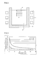
- Figure 3 is a diagram showing the relationship between the permeation depths D1 and D2 and the frequency f.
- the solid line in Figure 3 indicates the permeation depth D1 with respect to the frequency f.
- the broken line in Figure 3 indicates the permeation depth D2 with respect to the frequency f.
- calculation has been made supposing that the crucible 6 is a graphite crucible, the electric conductivity ⁇ c of the side wall is 1.25 ⁇ 10 5 (S/m), and the relative permeability ⁇ c thereof is 1.0.
- the calculation also has supposed that the electric conductivity ⁇ s of the SiC solution is 1 ⁇ 10 6 (S/m) and the relative permeability ⁇ s thereof is 1.0.
- both the permeation depths D1 and D2 sharply decline.
- the permeation depths D1 and D2 decline as the frequency f increases.
- the degrees of decline of the permeation depths D1 and D2 with respect to an increase of the frequency f become smaller.
- the permeation depths D1 and D2 do not decline so much even when the frequency f increases. From what described so far, as the frequency f increases, the permeation depths D1 and D2 defined by Formulas (2) and (3) decreases.
- Figures 4A to 6B are diagrams each showing a flow pattern of the SiC solution 8 when the frequency f is changed.
- Figures 4A, 5A and 6A respectively show a result of thermohydraulic analysis in the crucible 6 obtained by a numerical analysis simulation. These figures were obtained by the following method. Supposing an axially symmetric RZ system, the calculation of electromagnetic field analysis was performed by a finite element method, and the calculation of thermohydraulic analysis was performed by a differential method. A manufacturing apparatus having the same configuration as that of Figure 1 was set in the calculation model.
- the inner diameter (2R) of the crucible 6 was 130 mm, and the thickness T of the side wall 61 was 10 mm.
- the height H (see Figure 4A ) of the SiC solution 8 was 50 mm, and the outer diameters of the SiC seed crystal 9 and the seed shaft 41 were 50 mm.
- the 1/2 height portion of the induction heating unit 3 was set at the same height as that of the bottom surface of the crucible 6.
- the crucible 6 was a graphite crucible made of carbon. Under the aforementioned conditions, a thermohydraulic analysis in the SiC solution 8 was conducted when the frequency f of alternating current was set to 3, 5, and 10 kHz.
- Figure 4A shows a distribution of flow velocity vectors in the SiC solution 8 when the frequency f is 3 kHz.
- Figure 4B is a schematic diagram of a flow pattern in the SiC solution 8 of Figure 4A.
- Figure 5A is a distribution of flow velocity vectors in the SiC solution 8 when the frequency f is 5 kHz
- Figure 5B is a schematic diagram of the flow pattern in that case.
- Figure 6A is a distribution of flow velocity vectors in the SiC solution 8 when the frequency f is 10 kHz
- Figure 6B is a schematic diagram of the flow pattern in that case.
- Figures 4A to 6B are each a cross-sectional view of the right half of the crucible 6 with respect to the central axis thereof.
- directions of the arrow heads in Figures 4A, 5A and 6A each indicate the direction in which the SiC solution 8 flows, and the length of each arrow head indicates the magnitude of flow velocity.
- a swirl (hereafter, referred to as a main swirl MS) occurred near the side wall 61 in each of the cases where the frequency f was 3, 5, and 10 kHz.
- the main swirl MS goes up near the side wall 61 and goes down near the SiC seed crystal 9.
- a swirl smaller than the main swirl MS (hereafter, referred to as a sub swirl SS) occurs.
- the sub swirl SS which has a flow opposite to that of the main swirl MS, goes down near the side wall 61 and goes up inside the crucible 6.
- the flows of the main swirl MS and the sub swirl SS cause an upward flow F1 to occur below the SiC seed crystal 9.
- the flow of the main swirl MS becomes opposite to the flow of the main swirl MS when the frequency f is 3 kHz and 5 kHz. That is, the fluid goes down on the side of the side wall 61, of the main swirl MS, and goes up on the side of the center of the SiC solution 8.
- the flow velocity of the main swirl MS is small, and the size of the main swirl MS is also small. Further, the sub swirl SS does not occur. Since the flow velocity of the main swirl MS is weak, the upward flow portion (a fluid on the side of the center of the SiC solution 8) of the main swirl MS does not expand to near the central axis of the SiC solution 8. On that account, although the upward flow portion collides with the end portion of the seed crystal 9, a downward flow F2 in which fluid goes down is produced below a central portion of the SiC seed crystal 9.
- FIGS 7A to 7C are each a distribution diagram of flow vectors in the SiC solution 8 when the frequency is kept constant and the thickness of the side wall 61 is varied. These figures have been obtained by the following method.
- a manufacturing apparatus having the same configuration as in Figure 1 was set in the calculation model.
- the inner diameter 2R of the crucible 6 was 130 mm
- the height H of the SiC solution 8 was 50 mm
- the outer diameters of the SiC seed crystal 9 and the seed shaft 41 were 50 mm.
- the 1/2 height portion of the induction heating unit 3 was set at the same height as that of the bottom surface of the crucible 6.
- the crucible 6 was a graphite crucible made of carbon.
- the frequency f of alternating current was kept constant at 5 kHz.
- Figures 7A to 7C each show a portion near the SiC seed crystal 9, of a longitudinal section of the right half of the SiC solution 8.
- the directions of the arrow heads in Figures 7A to 7C each indicate the direction in which the SiC solution 8 flows, and the length of each arrow head indicates the flow velocity.
- the Lorentz force is further influenced by the inner radius R of the crucible 6.
- the permeation depth into the solution is as shallow as about 5 mm as shown in Figure 3 . Therefore, the Lorentz force concentrates near the outer layer of the solution. Therefore, as the inner radius R of the crucible 6 increases, it becomes more difficult for the flow by the Lorentz force to propagate to the central part of the SiC solution 8. On that account, as the inner radius R increases, the flow velocity of the upward flow F1 decreases, or the upward flow F1 becomes not likely to occur.
- the Lorentz force acting on the SiC solution 8 increases, an upward flow F1 having a larger flow velocity is likely to be produced. Further, the Lorentz force acting on the SiC solution 8 is influenced by the frequency f, the thickness T of the side wall 61, and the inner radius R of the crucible 6. To be specific, the Lorentz force acting on the SiC solution 8 increases, as the frequency f decreases, the thickness T decreases, and the inner radius R decreases. On that account, it becomes more likely that a main swirl MS and a sub swirl SS having a large flow velocity are produced in the SiC solution 8, and thus an upward flow F1 having a large flow velocity is produced.
- control unit 7 sets the frequency f such that it satisfies Formula (1), an upward flow F1 is produced in the SiC solution 8 and the flow velocity significantly increases.
- Figure 8 was obtained by the following method. Supposing an axially symmetric RZ system, the calculation of electromagnetic field analysis was performed by a finite element method, and the calculation of thermohydraulic analysis was performed by a differential method. A manufacturing apparatus having the same configuration as that of Figure 1 was set in the calculation model.
- the inner diameter 2R of the crucible 6 was set to 130 mm, and the thickness T of the side wall 61 to 10 mm.
- the height H of the SiC solution 8 was 50 mm, and the outer diameters of the SiC seed crystal 9 and the seed shaft were 50 mm.
- the 1/2 height portion of the induction heating unit 3 was set at the same height as that of the bottom surface of the crucible 6.
- the crucible 6 was a graphite crucible made of carbon.
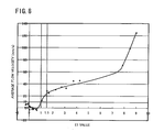
- the frequency f, the thickness T, and the inner radius R were varied. Then, the E1 value was determined for each condition. Further, for each simulation, an average flow velocity (mm/s) of a range from the center of the SiC seed crystal 9 to an end of the SiC seed crystal 9 (i.e., of a width of 25 mm and hereafter, this range being referred to as the "calculation area") was calculated at a position 5 mm below from the lower end of the SiC seed crystal 9, in the SiC solution 8. When an average flow velocity is plus (+), it indicates that the fluid (SiC solution 8) of the calculation area is going up at the calculated average flow velocity. When an average flow velocity is minus (-), it indicates that the fluid of the calculation area is going down at the calculated average flow velocity. Figure 8 was created based on the E1 values and average flow velocities which had been obtained.
- a preferred average flow velocity is not less than 10 mm/s.
- the average flow velocity was less than 10 mm/s and, as the E1 value increased, the average flow velocity gradually decreased into minus.
- the E1 value was more than 1, that is, satisfied Formula (1), the average flow velocity substantially increased and exceeded 10 mm/s.
- the average flow velocity substantially increased, and when the E1 value became not less than 1.5, the average flow velocity exceeded 20 mm/s.
- the E1 value became not less than 7.5, the average flow velocity substantially increased and exceeded 60 mm/s.
- control unit 7 performs adjustment that an alternating current of a frequency f that satisfies Formula (1) is passed to the induction heating unit 3. This will make it possible to produce an upward flow F1 having a large flow velocity below the SiC seed crystal 9.
- the E1 value is not less than 1.5. In this case, the average flow velocity of the fluid of the calculation area exceeds 20 mm/s.
- a method for manufacturing a SiC single crystal by using the manufacturing apparatus 100 having the above described configuration will be described.
- the manufacturing apparatus 100 is provided and a SiC seed crystal 9 is attached to the seed shaft 41 (providing step).
- the crucible 6 is disposed in the chamber 1 to produce the SiC solution (SiC solution production step).
- the SiC seed crystal 9 is brought into contact with the SiC solution in the crucible 6 (immersion step).
- the SiC single crystal is grown (growth step).
- growth step by passing an alternating current of a frequency f to the induction heating unit 3 by the control unit 7, an upward flow F1 having a large flow velocity is produced below the seed crystal 9 in the SiC solution 8. This will lead to an increase in the degree of supersaturation of carbon near the seed crystal 9, thereby accelerating the growth of the SiC single crystal.
- details of each step will be described.
- the manufacturing apparatus 100 including the seed shaft 41 is provided. Then, the SiC seed crystal 9 is attached to the lower end surface 410 of the seed shaft 41.
- the crucible 6 is disposed on the rotating member 51 in the chamber 1.
- the crucible 6 houses the starting material of SiC solution.
- the crucible 6 is preferably disposed in coaxial with the rotating member 51. In this case, when the rotating member 51 rotates, the temperature of the SiC solution in the crucible 6 is likely to be kept uniform.
- the SiC solution 8 is produced.
- Inert gas is filled in the chamber 1.
- the inert gas is, for example, helium and argon.
- the control unit 7 controls the induction heating unit 3 so as to inductively heat the starting material of the SiC solution 8 in the crucible 6 to not less than the melting point.
- carbon is contained in the inner surface of the side wall 61 of the crucible 6, heating the crucible 6 will cause carbon to dissolve into the melt from crucible 6, thereby producing a SiC solution 8.
- carbon is contained in the starting material of the SiC solution 8.
- the SiC solution 8 contains Si and C, and further may contain other metal elements.
- the SiC seed crystal 9 is brought into contact with the SiC solution 8.
- the seed shaft 41 is moved down by the driving source 42 to bring the SiC seed crystal 9 into contact with the SiC solution 8.
- control unit 7 controls the induction heating unit 3 to hold the SiC solution 8 at the crystal growth temperature. Further, the control unit 7 controls the induction heating unit 3 to stir the SiC solution 8, thereby forming the upward flow F1 below the SiC seed crystal 9.
- control unit 7 heats the SiC solution 8 to the crystal growth temperature, and stirs the SiC solution 8 to produce the upward flow F1.
- control unit 7 makes adjustment so that the frequency f of the alternating current to be passed to the induction heating unit 3 satisfies Formula (1). This will allow the control unit 7 to heat and stir the SiC solution 8, thereby producing an upward flow F1 having a large flow velocity.
- the control unit 7 further controls the induction heating unit 3 such that the SiC seed-crystal peripheral area of the SiC solution' 8 is supercooled, thereby being supersaturated with SiC.
- the method for cooling the SiC seed-crystal peripheral area is as follows.
- the control unit 7 controls the induction heating unit 3 so as to keep the temperature of the peripheral area of the SiC seed-crystal 9 to be lower than that of the other portion of the SiC solution 8.
- the peripheral area of the SiC seed-crystal 9 may be cooled with a coolant.
- a coolant is circulated inside the seed shaft 41.
- the coolant may be, for example, water. Circulating the coolant in the seed shaft 41 will cause the SiC seed crystal 9 to be cooled.
- the SiC seed crystal 9 and the Sic solution 8 are rotated while SiC in the peripheral area of the SiC seed-crystal 9 of the Sic solution 8 being kept supersaturated.
- Rotating the seed shaft 41 will cause the SiC seed crystal 9 to rotate.
- Rotating the rotating member 51 will cause the crucible 6 to rotate.
- the rotational direction of the SiC seed crystal 9 may be opposite to, or the same as that of the crucible 6.
- the rotational speed may be constant or variable.
- the seed shaft 41 gradually moves up while rotating. In this occasion, a SiC single crystal is produced and grown on the surface of the SiC seed crystal 9 which is in contact with the SiC solution 8.
- control unit 7 passes an alternating current of a frequency f that satisfies Formula (1) to the induction heating unit 3.
- an upward flow F1 is formed below the SiC seed crystal 9 in the SiC solution 8 by the Lorentz force produced by the induction heating unit 3.
- carbon is frequently fed to the vicinity of the SiC seed crystal 9 so that the degree of supersaturation of carbon in a portion near the SiC seed crystal 9 is maintained to be high.
- the control unit 7 sets a frequency f that satisfies Formula (1) and controls the induction heating unit 3. On that account, it is possible to maintain the degree of supersaturation of carbon in a portion near the seed crystal 9 at a high level, thereby accelerating the growth rate of the SiC single crystal.
- the inner surface of the side wall 61 of the crucible 6 preferably contains carbon.
- carbon dissolves into the SiC solution from the side wall 61 and is conveyed to below the SiC seed crystal 9 by the upward flow F1.
- the degree of supersaturation of carbon of a portion near the SiC seed crystal 9 is likely to increase.
- the crucible 6 is made of graphite.
- the manufacturing apparatus 100 includes the insulating member 2. However, the manufacturing apparatus 100 may not include the insulating member 2.
- simulations were carried out by varying the frequency f, the thickness T and the inner radius R, and analyzed the flow pattern in the SiC solution. Then, the flow velocity of the SiC solution below the SiC seed crystal was determined.
- the simulation was conducted as described below. Supposing an axially symmetric RZ system, the calculation of electromagnetic field analysis was performed by a finite element method, and the calculation of thermohydraulic analysis was performed by a differential method.
- a manufacturing apparatus 100 having the same configuration as that of Figure 1 was set in the calculation model.
- the inner diameter 2R of the crucible 6 was set to 130 mm, and the thickness T of the side wall 61 to 10 mm.
- the height H of the SiC solution 8 was 50 mm, and the outer diameters of the SiC seed crystal 9 and the seed shaft were 50 mm.
- the 1/2 height portion of the induction heating unit 3 was set at the same height as that of the bottom surface of the crucible 6.
- the crucible 6 was a graphite crucible made of carbon.
- Table 1 shows an E1 value. Referring to Table 1, simulations were carried out at 40 conditions in which the frequency f, the thickness T and the inner radius R were different.
- Table 2 represents an average flow velocity (mm/s). Referring to Tables 1 and 2, the average flow velocity when each condition satisfied Formula (1) was substantially higher compared with that when the each condition did not satisfy Formula (1).
Landscapes
- Chemical & Material Sciences (AREA)
- Engineering & Computer Science (AREA)
- Crystallography & Structural Chemistry (AREA)
- Materials Engineering (AREA)
- Metallurgy (AREA)
- Organic Chemistry (AREA)
- Inorganic Chemistry (AREA)
- Crystals, And After-Treatments Of Crystals (AREA)
Abstract

where, D1 is defined by Formula (2), and D2 by Formula (3):


where, σc is an electric conductivity (S/m) of the sidewall, and σs is an electric conductivity (S/m) of the SiC solution; µc is a relative permeability (dimensionless quantity) of the sidewall, and µs is a relative permeability (dimensionless quantity) of the SiC solution.
Description
- The present invention relates to a manufacturing apparatus of a silicon carbide (SiC) single crystal and a method for manufacturing a SiC single crystal, and more particularly to a manufacturing apparatus of a SiC single crystal by a solution growth method and a method for manufacturing a SiC single crystal.
- Silicon carbide (SiC) is a thermally and chemically stable compound semiconductor. Compared with silicon (Si), SiC has an excellent band gap, break down voltage, electron saturation velocity, and thermal conductivity. Therefore, SiC is promising for application in technical fields such as power device materials with low operating loss, high-voltage resistant high-frequency device materials, environment-resistant devices used in high-temperature environments, and radiation-resistant devices. In these technical fields, a high quality SiC single crystal with few crystal defects is demanded.
- Methods for manufacturing a SiC single crystal include a sublimation method and a solution growth method. Compared to the sublimation method, the solution growth method can produce a Sic single crystal with less crystal defects. The solution growth method of a SiC single crystal is a method of growing a SiC single crystal by bringing a SiC seed crystal into contact with a solution in which carbon (C) is dissolved into a melt containing Si or Si and additive elements (hereafter referred to as a SiC solution). In general, a crucible made of graphite is used, and carbon dissolves from the crucible to be fed into the SiC solution. The SiC seed crystal is attached to a lower end surface of a bar-shaped seed shaft and is brought into contact with the SiC solution.
- In the solution growth method, the temperature of the portion of the SiC solution in the periphery of the SiC seed crystal (hereafter, referred to as a SiC seed-crystal peripheral area) is kept lower than that of the other portion of SiC solution. This will cause a supersaturation of SiC in the SiC seed-crystal peripheral area, thereby accelerating the growth of the SiC single crystal.
- As described above, the solution growth method allows manufacture of a SiC single crystal which has less crystal defects than in the sublimation method. However, the growth rate of the SiC single crystal in the solution growth method is lower than in the sublimation method. For example, in a conventional solution growth method, the growth rate of SiC single crystal in solution growth method is about 5 to 12 µm/hr when a pure Si solution of 1650°C is used. This growth rate is not more than 1/10 of that of SiC single crystal in the sublimation method.
- The growth rate RA (m/s) of SiC single crystal in the solution growth method is defined by the Wilson-Frenkel formula shown in Formula (A):

where, A0 is a coefficient, ΔC is the degree of supersaturation of carbon (unit: mol/m3), ΔG is the energy (unit: J/mol) needed for taking away a solvent molecule from a solute molecule, k is the gas constant (unit: J/K·mol), and t is absolute temperature (K). - It can be seen from Formula (A) that increasing the degree of supersaturation (ΔC) of carbon in the SiC solution allows an increase in the growth rate RA of SiC single crystal. Increasing the feed rate of carbon to a portion near the SiC seed crystal, of the SiC solution will allow an increase in the degree of supersaturation of carbon (ΔC).
-
JP2006-117441A Patent Document 1 applies an accelerated crucible rotation technique (hereafter, referred to as ACRT method) to the solution growth method of SiC single crystal. In the ACRT method, acceleration and deceleration are repeated for the rotation of the SiC seed crystal and the rotation of the crucible. This will cause the SiC solution to be stirred, thereby facilitating feeding of carbon to the vicinity of the SiC seed crystal. - However, even in a method other than the ACRT method, it is preferable that carbon is more likely to be fed to a portion near the SiC seed crystal.
- It is an object of the present invention to provide a manufacturing apparatus of a SiC single crystal, in which carbon is more likely to be fed to a portion near a SiC seed crystal in a SiC solution in the manufacturing of a SiC single crystal by a solution growth method.
- A manufacturing apparatus of a SiC single crystal according to an embodiment of the present invention includes a crucible, a chamber, a vertical seed shaft, an induction heating unit, and a control unit. The crucible includes a tubular side wall and a bottom wall disposed at a lower end of the side wall. The crucible can house a SiC solution. The chamber houses the crucible. The seed shaft extends in an up-and-down direction of the chamber. The seed shaft, which has a lower end surface to which a SiC seed crystal is to be attached, is able to bring the SiC seed crystal attached to the lower end surface thereof into contact with the SiC solution. The induction heating unit is disposed around the side wall of the crucible in the chamber. The control unit controls the induction heating unit. The control unit controls the induction heating unit such that a frequency f (Hz) of alternating current to be passed to the induction heating unit satisfies Formula (1), where D1 (mm) indicates a permeation depth of electromagnetic waves into the side wall by the induction heating unit, D2 (mm) indicates a permeation depth of electromagnetic waves into the SiC solution by the induction heating unit, T (mm) indicates a thickness of the side wall, and R (mm) indicates an inner radius of the crucible :

where, D1 is defined by Formula (2), and D2 is defined by Formula (3):

where, σc is an electric conductivity of the side wall, σs is an electric conductivity of the SiC solution, µc is a relative permeability of the side wall, and µs is a relative permeability of the SiC solution. - In the manufacturing apparatus of a SiC single crystal according to an embodiment of the present invention, a SiC solution is heated by induction heating. Further, the SiC solution is stirred by a Lorentz force which is generated by induction heating, facilitating feeding of carbon to the vicinity of a SiC seed crystal.
- The method for manufacturing a SiC single crystal according to the present embodiment utilizes the above described manufacturing apparatus.
-
- [
Figure 1] Figure 1 is a schematic diagram of a manufacturing apparatus of a SiC single crystal according to an embodiment of the present invention. - [
Figure 2] Figure 2 is a schematic diagram for illustrating an upward flow which occurs in a SiC solution in the crucible inFigure 1 . - [
Figure 3] Figure 3 is a diagram showing the relationship between: permeation depth into the side wall of the crucible and permeation depth into the SiC solution of electromagnetic waves which is generated by an induction heating unit inFigure 1 ; and frequency f of alternating current flowing into the induction heating unit. - [
Figure 4A] Figure 4A is a distribution diagram of flow velocity vectors in the SiC solution when the frequency f is 3 kHz. - [
Figure 4B] Figure 4B is a schematic diagram of a flow pattern in the SiC solution ofFigure 4A . - [
Figure 5A] Figure 5A is a distribution diagram of flow velocity vectors in the SiC solution when the frequency f is 5 kHz. - [
Figure 5B] Figure 5B is a schematic diagram of a flow pattern in the SiC solution ofFigure 5A . - [
Figure 6A] Figure 6A is a distribution diagram of flow velocity vectors in the SiC solution when the frequency f is 10 kHz. - [
Figure 6B] Figure 6B is a schematic diagram of a flow pattern in the SiC solution ofFigure 6A . - [
Figure 7A] Figure 7A is a distribution diagram of flow velocity vectors in the SiC solution when the side wall thickness of the crucible is 5 mm. - [
Figure 7B] Figure 7B is a distribution diagram of flow velocity vectors in the SiC solution when the side wall thickness of the crucible is 10 mm. - [
Figure 7C] Figure 7C is a distribution diagram of flow velocity vectors in the SiC solution when the side wall thickness of the crucible is 15 mm. - [
Figure 8] Figure 8 is a diagram showing the relationship between the value of the left hand side, E1 = (D1 - T) × D2/R, of Formula (1) and the average flow velocity of upward flow. - Hereafter, embodiments of the present invention will be described in detail with reference to the drawings. The same or corresponding components in the drawings will be given the same reference characters and description thereof will not be repeated.
-
Figure 1 is a configuration diagram of a manufacturing apparatus of a SiC single crystal according to the present embodiment. Referring toFigure 1 , amanufacturing apparatus 100 includes achamber 1, aninsulating member 2, aninduction heating unit 3, an up-and-downmoving unit 4, arotation unit 5, acrucible 6, and acontrol unit 7. - The
chamber 1 is a housing and houses theinsulating member 2, theinduction heating unit 3, and acrucible 6. When a SiC single crystal is manufactured, thechamber 1 is water cooled. - The
rotation unit 5 includes a rotatingmember 51 and a drivingsource 52. The rotatingmember 51 has a bar-like shape and extends in the up-and-down direction of themanufacturing apparatus 100. Thecrucible 6 is disposed at the upper end of the rotatingmember 51. Thecrucible 6 may be fixed to the upper end of the rotatingmember 51. The lower end portion of the rotatingmember 51 is connected with the drivingsource 52. When a SiC single crystal is manufactured, therotation unit 5 rotates thecrucible 6. To be specific, the drivingsource 52 rotates the rotatingmember 51. On that account, thecrucible 6 rotates around the axial centerline of the rotatingmember 51. - The
crucible 6 is a housing which has an open upper end. Thecrucible 6 includes a tubular side wall 61 and abottom wall 62. In the present example, the side wall 61 is a cylinder. However, the side wall 61 will not be limited to a cylinder. The side wall 61 only needs to have a tube-shape. - The
bottom wall 62 is disposed at the lower end of the side wall 61 and is coupled to the side wall 61. Thebottom wall 62 may be integrally formed with the side wall 61, or may be coupled to the side wall 61 after they are formed separately. InFigure 1 , a corner A1 formed between the side wall 61 and thebottom wall 62 has a right angle. However, the corner A1 may be rounded. To be specific, the corner A1 may be provided with a corner radius. - The
crucible 6 houses aSiC solution 8. TheSiC solution 8, which is the starting material of SiC single crystal, contains silicon (Si) and carbon (C). TheSiC solution 8 may further contain one or more kinds of metal elements other than Si and C. - The
SiC solution 8 is produced by heating and melting the starting material of a SiC solution. The starting material may be a Si simple substance, or may contain Si and other metal elements. Examples of the metal element contained in the starting material of SiC solution include titan (Ti), manganese (Mn), chromium (Cr), cobalt (Co), vanadium (V), iron (Fe), and so on. Preferable elements to be contained in the starting material of the SiC solution are Ti and Mn, and a more preferable element is Ti. - The raw material of the
crucible 6 is, for example, graphite. When thecrucible 6 is made up of graphite, thecrucible 6 itself serves as a carbon source for the SiC solution. The raw material of thecrucible 6 may be other than graphite. For example, thecrucible 6 may be made up of ceramics or a high-melting-point metal. When thecrucible 6 cannot be used as a carbon source, the starting material of SiC solution will contain graphite (carbon). - Preferably, at least the inner surface of the side wall 61 of the
crucible 6 contains carbon. For example, a film made of SiC is formed on the inner surface of the side wall 61. In this case, carbon dissolves into the SiC solution from the film while a SiC single crystal is manufactured. More preferably, the inner surface of thecrucible 6 contains carbon. In short, the inner surfaces of the side wall 61 and thebottom wall 62 contain carbon. In this case, thecrucible 6 serves as a carbon source of the SiC solution. - The up-and-down moving
unit 4 includes aseed shaft 41 and a drivingsource 42. The drivingsource 42 is disposed above thechamber 1. Theseed shaft 41 is in a bar shape, and extends in the up-and-down direction of thechamber 1. The lower end of theseed shaft 41 is disposed in thechamber 1, and the upper end thereof is disposed above thechamber 1. That is, theseed shaft 41 penetrates through thechamber 1. Theseed shaft 41 is disposed in coaxial with the rotatingmember 51. - The upper end portion of the
seed shaft 41 is connected to the drivingsource 42. The drivingsource 42 drives theseed shaft 41 to move up and down. The drivingsource 42 further drives theseed shaft 41 to rotate around the central axis of theseed shaft 41. - The lower end of the
seed shaft 41 is disposed in thecrucible 6. Theseed shaft 41 has alower end surface 410. ASiC seed crystal 9 is attached to thelower end surface 410. - A
SiC seed crystal 9 is in a plate shape and made up of a SiC single crystal. When a SiC single crystal is manufactured by a solution growth method, the SiC single crystal is produced and grown on the surface of theSiC seed crystal 9. When a SiC single crystal having a crystal structure of 4H polymorphism is manufactured, theSiC seed crystal 9 is preferably a single crystal having a crystal structure of 4H polymorphism. More preferably, the surface of the SiC seed crystal 9 (corresponding to the lower surface of theSiC seed crystal 9 inFigure 1 ) is a (0001) plane or a plane inclined by an angle of not more than 8° from the (0001) plane. In this case, the SiC single crystal is likely to grow in a stable manner. - When a SiC single crystal is manufactured, the
seed shaft 41 is moved downward and, as shown inFigure 1 , theSiC seed crystal 9 is brought into contact with theSiC solution 8. At this moment, theSiC solution 8 is kept at a crystal growth temperature. The crystal growth temperature depends on the composition of theSiC solution 8. A typical crystal growth temperature is 1600 to 2000°C. - The insulating
member 2 is housing-shaped and has a side wall, an upper cover, and a lower cover. The side wall of the insulatingmember 2 is disposed around the side wall 61 of thecrucible 6. The upper cover of the insulatingmember 2 is disposed above thecrucible 6. The upper cover has a throughhole 21 for passing theseed shaft 41 therethrough. The lower cover of the insulatingmember 2 is disposed below thecrucible 6. The lower cover has a throughhole 22 for passing the rotatingmember 51 therethrough. In short, the insulatingmember 2 covers theentire crucible 6. - The insulating
member 2 includes a well-known insulating material. The insulating material is a fibrous or non-fibrous molded insulating material. In order to form a SiC single crystal having a diameter of not less than 2 inches, a high heating efficiency needs to be maintained. The insulatingmember 2 can maintain a high heating efficiency. - The
induction heating unit 3 is disposed around thecrucible 6. To be more specific, it is disposed in the outer circumference of the insulatingmember 2. In the present example, theinduction heating unit 3 is a ringshaped high-frequency coil and is disposed in coaxial with theseed shaft 41 and the rotatingmember 51. Theinduction heating unit 3 inductively heats thecrucible 6 and thereby melts the starting material housed in thecrucible 6, thus producing aSiC solution 8. Theinduction heating unit 3 further provides a Lorentz force to theSiC solution 8, thereby stirring theSiC solution 8. - The
control unit 7 controls theentire manufacturing apparatus 100. Therefore, thecontrol unit 7 also controls theinduction heating unit 3. Thecontrol unit 7 includes, although not shown, a central processing unit (CPU) and memories (ROM and RAM). The ROM stores a control program of theinduction heating unit 3. Thecontrol unit 7 controls theinduction heating unit 3 by the control program being loaded on the RAM from the ROM and executed by the CPU. - The
control unit 7 adjusts the frequency f of the alternating current to be passed to theinduction heating unit 3. By doing this, thecontrol unit 7 heats theSiC solution 8 to a crystal growth temperature, and stirs the SiC solution, facilitating feeding of carbon to the vicinity of theSiC seed crystal 9. Hereafter, this point will be described. - As described above, to increase the growth rate of a SiC single crystal in the solution growth method, it may be arranged such that the degree of supersaturation (ΔC) of carbon is increased in a portion near the
SiC seed crystal 9, of theSiC solution 8. And to increase the degree of supersaturation of carbon in the vicinity of theSiC seed crystal 9, it may be arranged such that carbon in the SiC solution can be easily conveyed to the vicinity of theSiC seed crystal 9 while a SiC single crystal is manufactured. - When alternating current is passed to the
induction heating unit 3, a Lorentz force is produced in theSiC solution 8. To be specific, as the alternating current that flows in the coil of theinduction heating unit 3 varies with time, the magnetic field will also vary with time. The orientation of the magnetic field reverses each time the direction of current that flows in theinduction heating unit 3 changes. So as to cancel such variation of magnetic field, an eddy current, which flows in the opposite direction to that of the current that flows in the coil, occurs in theSiC solution 8. This phenomenon is electromagnetic induction, and Joule heat is generated by the eddy current, which is generated by electromagnetic induction, in theSiC solution 8 and thecrucible 9. Further, a Lorentz force (electromagnetic force) acting from the vicinity of the outer circumference of theSiC solution 8 toward the center of theSiC solution 8 is generated in theSiC solution 8 by the interaction between the eddy current and the magnetic field. - The
induction heating unit 3 causes a Lorentz force to act in theSiC solution 8. Then, theSiC solution 8 is stirred in thecrucible 6 by the Lorentz force. It is preferable that as the result of theSiC solution 8 being stirred, an upward flow F1 is formed below theSiC seed crystal 9 in theSiC solution 8 as shown inFigure 2 . This is because, owing to the upward flow F1, carbon in theSiC solution 8 becomes more likely to be conveyed to the vicinity of theSiC seed crystal 9 so that the degree of supersaturation of carbon (ΔC) in a portion near theSiC seed crystal 9 of theSiC solution 8 increases. Further, when the inner surface of the side wall 61 of thecrucible 6 contains carbon, carbon that has dissolved into theSiC solution 8 from the side wall 61 is conveyed to the vicinity of theSiC seed crystal 9 by the upward flow F1. - Further, a larger flow velocity of the upward flow F1 is preferable. That is because, as the flow velocity increases, the feed rate of carbon to the vicinity of the
SiC seed crystal 9 increases. Therefore, it is preferable that an upward flow F1 having a large flow velocity is produced by a Lorentz force. - When the frequency f of a two-phase or three-phase alternating current is a low frequency (less than 100 Hz) in induction heating, it is possible to control the direction of a Lorentz force. However, since the heat quantity of induction heating is small at a frequency as low as about 100 Hz, it is difficult to heat the
SiC solution 8 to 1600 to 2000°C. Therefore, for theinduction heating unit 3 to heat the SiC solution up to 1600 to 2000°C, the frequency f is preferably a high frequency of not less than 1 kHz. - When the frequency f is a high frequency (not less than 1 kHz), although it is not possible to control the direction of the Lorentz force, it is possible to control the magnitude of the Lorentz force. In the
manufacturing apparatus 100 in the present embodiment, theinduction heating unit 3 can heat theSiC solution 8, and produces an upward flow F1 having a large flow velocity, thecontrol unit 7 controls theinduction heating unit 3 such that the frequency f (Hz) of the alternating current to be passed to theinduction heating unit 3 satisfies Formula (1):
where, T is the thickness (mm) of the side wall 61, and R is the inner radius (mm) of thecrucible 6; D1 is defined by Formula (2), and D2 is defined by Formula (3):

where, σc is the electric conductivity (S/m) of the sidewall 61, and σs is the electric conductivity (S/m) of theSiC solution 8. Also µc is the relative permeability of the sidewall 61 and µs is the relative permeability of theSiC solution 8, where µc and µs are dimensionless quantities. - The thickness T is determined, for example, by the following method. As shown in
Figure 1 , the thickness T is an average value of thickness of a portion of the side wall 61 in contact with theSiC solution 8. However, when a corner A1 which is made up of the inner surface of the side wall 61 and the inner surface of thebottom wall 62 forms a corner radius, the thickness of the corner A1 will not be included into the average value. - Hereafter, Formula (1) will be described. The Lorentz force is proportional to electromagnetic waves generated from the
induction heating unit 3. The electromagnetic waves generated at theinduction heating unit 3 attenuate as they pass through a conductor. The electromagnetic waves in a conductor attenuate at an exponential rate. Here, the "permeation depth" of electromagnetic waves is defined as the depth at which the electromagnetic wave intensity is exp(-1) (about 1/3) times of the value at the surface of the conductor. - The side wall 61 of the
crucible 6 and theSiC solution 8 are both conductors. Therefore, the electromagnetic waves generated at theinduction heating unit 3 attenuate in the side wall 61 and theSiC solution 8. The Lorentz force is proportional to electromagnetic waves. Therefore, the Lorentz force is proportional to the permeation depth of electromagnetic waves. - The permeation depth in the side wall 61 of the
crucible 6 is defined by D1 (Formula (2)). Further, the permeation depth in theSiC solution 8 is defined by D2 (Formula (3)). -
Figure 3 is a diagram showing the relationship between the permeation depths D1 and D2 and the frequency f. The solid line inFigure 3 indicates the permeation depth D1 with respect to the frequency f. The broken line inFigure 3 indicates the permeation depth D2 with respect to the frequency f. InFigure 3 , calculation has been made supposing that thecrucible 6 is a graphite crucible, the electric conductivity σc of the side wall is 1.25 × 10⁵ (S/m), and the relative permeability µc thereof is 1.0. The calculation also has supposed that the electric conductivity σs of the SiC solution is 1 × 10⁶ (S/m) and the relative permeability µs thereof is 1.0. - Referring to
Figure 3 , as the frequency f increases up to 10 kHz, both the permeation depths D1 and D2 sharply decline. When the frequency f is more than 10 kHz, the permeation depths D1 and D2 decline as the frequency f increases. However, compared with when the frequency is less than 10 kHz, the degrees of decline of the permeation depths D1 and D2 with respect to an increase of the frequency f become smaller. In short, when the frequency f is more than 10 kHz, the permeation depths D1 and D2 do not decline so much even when the frequency f increases. From what described so far, as the frequency f increases, the permeation depths D1 and D2 defined by Formulas (2) and (3) decreases. -
Figures 4A to 6B are diagrams each showing a flow pattern of theSiC solution 8 when the frequency f is changed.Figures 4A, 5A and 6A respectively show a result of thermohydraulic analysis in thecrucible 6 obtained by a numerical analysis simulation. These figures were obtained by the following method. Supposing an axially symmetric RZ system, the calculation of electromagnetic field analysis was performed by a finite element method, and the calculation of thermohydraulic analysis was performed by a differential method. A manufacturing apparatus having the same configuration as that ofFigure 1 was set in the calculation model. The inner diameter (2R) of thecrucible 6 was 130 mm, and the thickness T of the side wall 61 was 10 mm. The height H (seeFigure 4A ) of theSiC solution 8 was 50 mm, and the outer diameters of theSiC seed crystal 9 and theseed shaft 41 were 50 mm. The 1/2 height portion of theinduction heating unit 3 was set at the same height as that of the bottom surface of thecrucible 6. Thecrucible 6 was a graphite crucible made of carbon. Under the aforementioned conditions, a thermohydraulic analysis in theSiC solution 8 was conducted when the frequency f of alternating current was set to 3, 5, and 10 kHz. -
Figure 4A shows a distribution of flow velocity vectors in theSiC solution 8 when the frequency f is 3 kHz.Figure 4B is a schematic diagram of a flow pattern in theSiC solution 8 ofFigure 4A. Figure 5A is a distribution of flow velocity vectors in theSiC solution 8 when the frequency f is 5 kHz, andFigure 5B is a schematic diagram of the flow pattern in that case.Figure 6A is a distribution of flow velocity vectors in theSiC solution 8 when the frequency f is 10 kHz, andFigure 6B is a schematic diagram of the flow pattern in that case.Figures 4A to 6B are each a cross-sectional view of the right half of thecrucible 6 with respect to the central axis thereof. Moreover, directions of the arrow heads inFigures 4A, 5A and 6A each indicate the direction in which theSiC solution 8 flows, and the length of each arrow head indicates the magnitude of flow velocity. - Referring to
Figures 4A to 6B , a swirl (hereafter, referred to as a main swirl MS) occurred near the side wall 61 in each of the cases where the frequency f was 3, 5, and 10 kHz. The lower the frequency was, the larger the flow velocity of the main swirl MS was. That is, the flow velocity of the main swirl MS was maximum at the frequency f = 3 kHz, and minimum at the frequency f = 10 kHz. When the frequency is 3 kHz (Figures 4A and 4B ), the main swirl MS goes up near the side wall 61 and goes down near theSiC seed crystal 9. When the frequency f = 3 kHz, further, a swirl smaller than the main swirl MS (hereafter, referred to as a sub swirl SS) occurs. The sub swirl SS, which has a flow opposite to that of the main swirl MS, goes down near the side wall 61 and goes up inside thecrucible 6. The flows of the main swirl MS and the sub swirl SS cause an upward flow F1 to occur below theSiC seed crystal 9. - Referring to
Figures 5A and 5B , when the frequency f is 5 kHz as well, the main swirl MS goes up near the side wall 61 and goes down near theSiC seed crystal 9, as in the case where the frequency f = 3 kHz. Further, a sub swirl SS also occurs. On that account, the flows of the main swirl MS and the sub swirl SS cause an upward flow F1 to occur below theSiC seed crystal 9. However, as described above, the flow velocity of the main swirl MS is smaller than that when the frequency f = 3 kHz, and the flow velocity of the sub swirl SS is also small. Therefore, the flow velocity of the upward flow F1 is smaller than that when the frequency f = 3 kHz. - Referring to
Figures 6A and 6B , when the frequency f is 10 kHz, the flow of the main swirl MS becomes opposite to the flow of the main swirl MS when the frequency f is 3 kHz and 5 kHz. That is, the fluid goes down on the side of the side wall 61, of the main swirl MS, and goes up on the side of the center of theSiC solution 8. The flow velocity of the main swirl MS is small, and the size of the main swirl MS is also small. Further, the sub swirl SS does not occur. Since the flow velocity of the main swirl MS is weak, the upward flow portion (a fluid on the side of the center of the SiC solution 8) of the main swirl MS does not expand to near the central axis of theSiC solution 8. On that account, although the upward flow portion collides with the end portion of theseed crystal 9, a downward flow F2 in which fluid goes down is produced below a central portion of theSiC seed crystal 9. - From the aforementioned simulation results, the lower the frequency f is, the more likely the upward flow F1 occurs below the
SiC seed crystal 9, and the flow velocity of the upward flow F1 increases. That is, it is more likely that a sub swirl SS is produced along with a main swirl MS, and an upward flow F1 is produced, when the permeation depths D1 and D2 are increased so that the Lorentz force permeates into the inside of theSiC solution 8. - The Lorentz force is further influenced by the thickness T of the side wall 61.
Figures 7A to 7C are each a distribution diagram of flow vectors in theSiC solution 8 when the frequency is kept constant and the thickness of the side wall 61 is varied. These figures have been obtained by the following method. A manufacturing apparatus having the same configuration as inFigure 1 was set in the calculation model. The inner diameter 2R of thecrucible 6 was 130 mm, the height H of theSiC solution 8 was 50 mm, and the outer diameters of theSiC seed crystal 9 and theseed shaft 41 were 50 mm. The 1/2 height portion of theinduction heating unit 3 was set at the same height as that of the bottom surface of thecrucible 6. Thecrucible 6 was a graphite crucible made of carbon. The frequency f of alternating current was kept constant at 5 kHz. - Under the aforementioned conditions, a flow velocity vector distribution in the
SiC solution 8 was analyzed when the thickness T of the side wall 61 of thecrucible 6 was set to 5 mm, 10 mm, and 15 mm.Figure 7A is a distribution diagram of flow velocity vectors in thecrucible 6 when the thickness T = 5 mm.Figure 7B is a distribution diagram of flow velocity vectors in thecrucible 6 when the thickness T = 10 mm.Figure 7C is a distribution diagram of flow velocity vectors in thecrucible 6 when the thickness T = 15 mm.Figures 7A to 7C each show a portion near theSiC seed crystal 9, of a longitudinal section of the right half of theSiC solution 8. The directions of the arrow heads inFigures 7A to 7C each indicate the direction in which theSiC solution 8 flows, and the length of each arrow head indicates the flow velocity. - Referring to
Figures 7A to 7C , when the thickness T = 5 mm and 10 mm (Figures 7A and 7B ), an upward flow F1 was formed. But, when the thickness T = 15 mm (Figure 7C ), no upward flow F1 was formed. Further, the flow velocity of the upward flow F1 was larger when the thickness T = 5 mm (Figure 7A ) than when the thickness T = 10 mm (Figure 7B ). - From the aforementioned simulation results, it can be seen that as the thickness T decreases, the flow velocity of the upward flow F1 below the
SiC seed crystal 9 increases. This is because, as the thickness T increases, it becomes more difficult for the Lorentz force to permeate into theSiC solution 8. - The Lorentz force is further influenced by the inner radius R of the
crucible 6. To be specific, the permeation depth into the solution is as shallow as about 5 mm as shown inFigure 3 . Therefore, the Lorentz force concentrates near the outer layer of the solution. Therefore, as the inner radius R of thecrucible 6 increases, it becomes more difficult for the flow by the Lorentz force to propagate to the central part of theSiC solution 8. On that account, as the inner radius R increases, the flow velocity of the upward flow F1 decreases, or the upward flow F1 becomes not likely to occur. - From what described so far, as the Lorentz force acting on the
SiC solution 8 increases, an upward flow F1 having a larger flow velocity is likely to be produced. Further, the Lorentz force acting on theSiC solution 8 is influenced by the frequency f, the thickness T of the side wall 61, and the inner radius R of thecrucible 6. To be specific, the Lorentz force acting on theSiC solution 8 increases, as the frequency f decreases, the thickness T decreases, and the inner radius R decreases. On that account, it becomes more likely that a main swirl MS and a sub swirl SS having a large flow velocity are produced in theSiC solution 8, and thus an upward flow F1 having a large flow velocity is produced. - Further, when the
control unit 7 sets the frequency f such that it satisfies Formula (1), an upward flow F1 is produced in theSiC solution 8 and the flow velocity significantly increases. -
Figure 8 is a diagram showing the relationship between the value of the left hand side, E1 = (D1 - T) × D2/R, of Formula (1) and the average flow velocity of the upward flow F1.Figure 8 was obtained by the following method. Supposing an axially symmetric RZ system, the calculation of electromagnetic field analysis was performed by a finite element method, and the calculation of thermohydraulic analysis was performed by a differential method. A manufacturing apparatus having the same configuration as that ofFigure 1 was set in the calculation model. The inner diameter 2R of thecrucible 6 was set to 130 mm, and the thickness T of the side wall 61 to 10 mm. The height H of theSiC solution 8 was 50 mm, and the outer diameters of theSiC seed crystal 9 and the seed shaft were 50 mm. The 1/2 height portion of theinduction heating unit 3 was set at the same height as that of the bottom surface of thecrucible 6. Thecrucible 6 was a graphite crucible made of carbon. - For each simulation, the frequency f, the thickness T, and the inner radius R were varied. Then, the E1 value was determined for each condition. Further, for each simulation, an average flow velocity (mm/s) of a range from the center of the
SiC seed crystal 9 to an end of the SiC seed crystal 9 (i.e., of a width of 25 mm and hereafter, this range being referred to as the "calculation area") was calculated at aposition 5 mm below from the lower end of theSiC seed crystal 9, in theSiC solution 8. When an average flow velocity is plus (+), it indicates that the fluid (SiC solution 8) of the calculation area is going up at the calculated average flow velocity. When an average flow velocity is minus (-), it indicates that the fluid of the calculation area is going down at the calculated average flow velocity.Figure 8 was created based on the E1 values and average flow velocities which had been obtained. - In the manufacturing of a SiC single crystal by the solution growth method, a preferred average flow velocity is not less than 10 mm/s. Referring to
Figure 8 , when the E1 value was less than 1, the average flow velocity was less than 10 mm/s and, as the E1 value increased, the average flow velocity gradually decreased into minus. On the other hand, when the E1 value was more than 1, that is, satisfied Formula (1), the average flow velocity substantially increased and exceeded 10 mm/s. Further, as the E1 value increased, the average flow velocity substantially increased, and when the E1 value became not less than 1.5, the average flow velocity exceeded 20 mm/s. Further, when the E1 value became not less than 7.5, the average flow velocity substantially increased and exceeded 60 mm/s. - From what described so far, the
control unit 7 performs adjustment that an alternating current of a frequency f that satisfies Formula (1) is passed to theinduction heating unit 3. This will make it possible to produce an upward flow F1 having a large flow velocity below theSiC seed crystal 9. Preferably, the E1 value is not less than 1.5. In this case, the average flow velocity of the fluid of the calculation area exceeds 20 mm/s. - A method for manufacturing a SiC single crystal by using the
manufacturing apparatus 100 having the above described configuration will be described. In the method for manufacturing a SiC single crystal, first, themanufacturing apparatus 100 is provided and aSiC seed crystal 9 is attached to the seed shaft 41 (providing step). Next, thecrucible 6 is disposed in thechamber 1 to produce the SiC solution (SiC solution production step). Next, theSiC seed crystal 9 is brought into contact with the SiC solution in the crucible 6 (immersion step). Next, the SiC single crystal is grown (growth step). In the growth step, by passing an alternating current of a frequency f to theinduction heating unit 3 by thecontrol unit 7, an upward flow F1 having a large flow velocity is produced below theseed crystal 9 in theSiC solution 8. This will lead to an increase in the degree of supersaturation of carbon near theseed crystal 9, thereby accelerating the growth of the SiC single crystal. Hereafter, details of each step will be described. - First, the
manufacturing apparatus 100 including theseed shaft 41 is provided. Then, theSiC seed crystal 9 is attached to thelower end surface 410 of theseed shaft 41. - Next, the
crucible 6 is disposed on the rotatingmember 51 in thechamber 1. Thecrucible 6 houses the starting material of SiC solution. Thecrucible 6 is preferably disposed in coaxial with the rotatingmember 51. In this case, when the rotatingmember 51 rotates, the temperature of the SiC solution in thecrucible 6 is likely to be kept uniform. - Next, the
SiC solution 8 is produced. Inert gas is filled in thechamber 1. The inert gas is, for example, helium and argon. Next, thecontrol unit 7 controls theinduction heating unit 3 so as to inductively heat the starting material of theSiC solution 8 in thecrucible 6 to not less than the melting point. When carbon is contained in the inner surface of the side wall 61 of thecrucible 6, heating thecrucible 6 will cause carbon to dissolve into the melt fromcrucible 6, thereby producing aSiC solution 8. When thecrucible 6 does not contain carbon, carbon is contained in the starting material of theSiC solution 8. TheSiC solution 8 contains Si and C, and further may contain other metal elements. - Next, the
SiC seed crystal 9 is brought into contact with theSiC solution 8. To be specific, theseed shaft 41 is moved down by the drivingsource 42 to bring theSiC seed crystal 9 into contact with theSiC solution 8. - After bringing the
SiC seed crystal 9 into contact with theSiC solution 8, thecontrol unit 7 controls theinduction heating unit 3 to hold theSiC solution 8 at the crystal growth temperature. Further, thecontrol unit 7 controls theinduction heating unit 3 to stir theSiC solution 8, thereby forming the upward flow F1 below theSiC seed crystal 9. - In short, the
control unit 7 heats theSiC solution 8 to the crystal growth temperature, and stirs theSiC solution 8 to produce the upward flow F1. To be specific, thecontrol unit 7 makes adjustment so that the frequency f of the alternating current to be passed to theinduction heating unit 3 satisfies Formula (1). This will allow thecontrol unit 7 to heat and stir theSiC solution 8, thereby producing an upward flow F1 having a large flow velocity. - The
control unit 7 further controls theinduction heating unit 3 such that the SiC seed-crystal peripheral area of the SiC solution' 8 is supercooled, thereby being supersaturated with SiC. The method for cooling the SiC seed-crystal peripheral area is as follows. For example, thecontrol unit 7 controls theinduction heating unit 3 so as to keep the temperature of the peripheral area of the SiC seed-crystal 9 to be lower than that of the other portion of theSiC solution 8. Moreover, the peripheral area of the SiC seed-crystal 9 may be cooled with a coolant. To be specific, a coolant is circulated inside theseed shaft 41. The coolant may be, for example, water. Circulating the coolant in theseed shaft 41 will cause theSiC seed crystal 9 to be cooled. When theSiC seed crystal 9 is cooled, a portion near theSiC seed crystal 9 will also be cooled. When the peripheral area of the SiC seed-crystal 9 is brought into a supercooled state by the above described method, the SiC concentration increases and becomes supersaturated. - Subsequently, the
SiC seed crystal 9 and theSic solution 8 are rotated while SiC in the peripheral area of the SiC seed-crystal 9 of theSic solution 8 being kept supersaturated. Rotating theseed shaft 41 will cause theSiC seed crystal 9 to rotate. Rotating the rotatingmember 51 will cause thecrucible 6 to rotate. The rotational direction of theSiC seed crystal 9 may be opposite to, or the same as that of thecrucible 6. Moreover, the rotational speed may be constant or variable. Theseed shaft 41 gradually moves up while rotating. In this occasion, a SiC single crystal is produced and grown on the surface of theSiC seed crystal 9 which is in contact with theSiC solution 8. At this moment, thecontrol unit 7 passes an alternating current of a frequency f that satisfies Formula (1) to theinduction heating unit 3. On account of that, an upward flow F1 is formed below theSiC seed crystal 9 in theSiC solution 8 by the Lorentz force produced by theinduction heating unit 3. Thus, carbon is frequently fed to the vicinity of theSiC seed crystal 9 so that the degree of supersaturation of carbon in a portion near theSiC seed crystal 9 is maintained to be high. - From what described so far, in the method for manufacturing a SiC according to the present invention, the
control unit 7 sets a frequency f that satisfies Formula (1) and controls theinduction heating unit 3.
On that account, it is possible to maintain the degree of supersaturation of carbon in a portion near theseed crystal 9 at a high level, thereby accelerating the growth rate of the SiC single crystal. - The inner surface of the side wall 61 of the
crucible 6 preferably contains carbon. In this case, carbon dissolves into the SiC solution from the side wall 61 and is conveyed to below theSiC seed crystal 9 by the upward flow F1. On that account, the degree of supersaturation of carbon of a portion near theSiC seed crystal 9 is likely to increase. More preferably, thecrucible 6 is made of graphite. - In the above describe embodiment, the
manufacturing apparatus 100 includes the insulatingmember 2. However, themanufacturing apparatus 100 may not include the insulatingmember 2. - In the above described method for manufacturing a SiC single crystal, simulations were carried out by varying the frequency f, the thickness T and the inner radius R, and analyzed the flow pattern in the SiC solution. Then, the flow velocity of the SiC solution below the SiC seed crystal was determined.
- The simulation was conducted as described below. Supposing an axially symmetric RZ system, the calculation of electromagnetic field analysis was performed by a finite element method, and the calculation of thermohydraulic analysis was performed by a differential method. A
manufacturing apparatus 100 having the same configuration as that ofFigure 1 was set in the calculation model. The inner diameter 2R of thecrucible 6 was set to 130 mm, and the thickness T of the side wall 61 to 10 mm. The height H of theSiC solution 8 was 50 mm, and the outer diameters of theSiC seed crystal 9 and the seed shaft were 50 mm. The 1/2 height portion of theinduction heating unit 3 was set at the same height as that of the bottom surface of thecrucible 6. Thecrucible 6 was a graphite crucible made of carbon. - For each simulation, the frequency f, the thickness T, and the inner radius R were varied. Then, Formula (1) was determined for each condition. The values at each condition are shown in Table 1.
[Table 1]
- Each field in Table 1 shows an E1 value. Referring to Table 1, simulations were carried out at 40 conditions in which the frequency f, the thickness T and the inner radius R were different.
- The electromagnetic field analysis and thermohydraulic analysis were carried out for each condition to obtain flow analysis results as shown in
Figures 6A ,7A , and8A. Based on these results, an average flow velocity (mm/s) of a range from the center of the SiC seed crystal to an end of the seed crystal (i.e., of a width of 25 mm) was calculated at aposition 5 mm below from the lower end of the SiC seed crystal. The calculated results of average flow velocity are shown in Table 2.
[Table 2]
- The value in each field in Table 2 represents an average flow velocity (mm/s). Referring to Tables 1 and 2, the average flow velocity when each condition satisfied Formula (1) was substantially higher compared with that when the each condition did not satisfy Formula (1).
- Although embodiments of the present invention have been described so far, the above described embodiments are merely exemplification for carrying out the present invention. Therefore, the present invention will not be limited to the embodiments described above, and the above described embodiments can be appropriately modified and carried out within a range not departing from the spirit of the present invention.
Claims (3)
- A manufacturing apparatus of a SiC single crystal, comprising:a crucible including a tubular side wall and a bottom wall disposed at a lower end of the side wall, the crucible being able to house a SiC solution;a chamber housing the crucible;a vertical seed shaft having a lower end surface to which a SiC seed crystal is to be attached, the seed shaft being able to bring the SiC seed crystal attached to the lower end surface into contact with the SiC solution;an induction heating unit disposed around the side wall of the crucible in the chamber; anda control unit for controlling the induction heating unit, whereinthe control unit controls the induction heating unit such that a frequency f (Hz) of alternating current to be passed to the induction heating unit satisfies Formula (1), where D1 (mm) indicates a permeation depth of electromagnetic waves into the side wall by the induction heating unit, D2 (mm) indicates a permeation depth of electromagnetic waves into the SiC solution by the induction heating unit, T (mm) indicates a thickness of the side wall, and R (mm) indicates an inner radius of the crucible:

where, D1 is defined by Formula (2), and D2 is defined by Formula (3):

where, σc is an electric conductivity (S/m) of the side wall, σs is an electric conductivity (S/m) of the SiC solution, µc is a relative permeability (dimensionless quantity) of the side wall, and µs is a relative permeability (dimensionless quantity) of the SiC solution. - The manufacturing apparatus according to claim 1, wherein
an inner surface of the side wall of the crucible contains carbon. - A method for manufacturing a SiC single crystal, comprising the steps of:providing a manufacturing apparatus comprising: a crucible including a tubular side wall and a bottom wall disposed at a lower end of the side wall, the crucible housing a SiC solution; a chamber housing the crucible; a vertical seed shaft, a SiC seed crystal attached to a lower end surface of the seed shaft; and an induction heating unit disposed around the side wall of the crucible in the chamber;bringing the SiC seed crystal attached to the seed shaft into contact with the SiC solution in the crucible;controlling the induction heating unit such that a frequency f (Hz) of alternating current to be passed to the induction heating unit satisfies Formula (1), where D1 (mm) indicates a permeation depth of electromagnetic waves into the side wall by the induction heating unit, D2 (mm) indicates a permeation depth of electromagnetic waves into the SiC solution by the induction heating unit, T (mm) indicates a thickness of the side wall, and R (mm) indicates an inner radius of the crucible,; andgrowing a SiC single crystal on the SiC seed crystal while rotating the seed shaft:

where, D1 is defined by Formula (2), and D2 is defined by Formula (3):

Applications Claiming Priority (2)
| Application Number | Priority Date | Filing Date | Title |
|---|---|---|---|
| JP2010289345 | 2010-12-27 | ||
| PCT/JP2011/080098 WO2012090946A1 (en) | 2010-12-27 | 2011-12-26 | APPARATUS FOR PRODUCING SiC SINGLE CRYSTAL AND METHOD FOR PRODUCING SiC SINGLE CRYSTAL |
Publications (3)
| Publication Number | Publication Date |
|---|---|
| EP2660368A1 true EP2660368A1 (en) | 2013-11-06 |
| EP2660368A4 EP2660368A4 (en) | 2014-05-14 |
| EP2660368B1 EP2660368B1 (en) | 2018-04-25 |
Family
ID=46383047
Family Applications (1)
| Application Number | Title | Priority Date | Filing Date |
|---|---|---|---|
| EP11854203.4A Not-in-force EP2660368B1 (en) | 2010-12-27 | 2011-12-26 | APPARATUS FOR PRODUCING SiC SINGLE CRYSTAL AND METHOD FOR PRODUCING SiC SINGLE CRYSTAL |
Country Status (7)
| Country | Link |
|---|---|
| US (1) | US9617655B2 (en) |
| EP (1) | EP2660368B1 (en) |
| JP (1) | JP5854438B2 (en) |
| KR (1) | KR101488125B1 (en) |
| CN (1) | CN103282559B (en) |
| TW (1) | TWI452183B (en) |
| WO (1) | WO2012090946A1 (en) |
Families Citing this family (8)
| Publication number | Priority date | Publication date | Assignee | Title |
|---|---|---|---|---|
| PL2572815T3 (en) * | 2011-09-22 | 2015-08-31 | MTU Aero Engines AG | Multi-frequency induction heating of generated components |
| WO2016056599A1 (en) * | 2014-10-10 | 2016-04-14 | 新日鐵住金株式会社 | Device for manufacturing silicon carbide single crystals and method for manufacturing silicon carbide single crystals |
| JP6094605B2 (en) * | 2015-01-20 | 2017-03-15 | トヨタ自動車株式会社 | Single crystal manufacturing equipment |
| JP6287870B2 (en) * | 2015-01-22 | 2018-03-07 | トヨタ自動車株式会社 | Method for producing SiC single crystal |
| WO2016148207A1 (en) * | 2015-03-18 | 2016-09-22 | 新日鐵住金株式会社 | SiC SINGLE CRYSTAL PRODUCTION METHOD |
| JP6256411B2 (en) * | 2015-05-18 | 2018-01-10 | トヨタ自動車株式会社 | Method for producing SiC single crystal |
| JP6558394B2 (en) * | 2017-04-26 | 2019-08-14 | トヨタ自動車株式会社 | Method and apparatus for producing SiC single crystal |
| CN109371466A (en) * | 2018-11-26 | 2019-02-22 | 国宏中晶集团有限公司 | A kind of growth of carborundum crystals electric-resistivity method power supply and its method |
Family Cites Families (10)
| Publication number | Priority date | Publication date | Assignee | Title |
|---|---|---|---|---|
| JP4389574B2 (en) * | 2003-12-16 | 2009-12-24 | 住友金属工業株式会社 | SiC single crystal manufacturing method and manufacturing apparatus |
| JP4475091B2 (en) | 2004-10-19 | 2010-06-09 | 住友金属工業株式会社 | Method for producing silicon carbide single crystal |
| JP4513749B2 (en) * | 2006-01-04 | 2010-07-28 | 住友金属工業株式会社 | Method for producing single crystal |
| JP4830496B2 (en) * | 2006-01-12 | 2011-12-07 | トヨタ自動車株式会社 | Method for producing SiC single crystal |
| JP4645496B2 (en) * | 2006-03-24 | 2011-03-09 | 住友金属工業株式会社 | Single crystal manufacturing apparatus and manufacturing method |
| EP2022294A4 (en) * | 2006-05-30 | 2014-04-16 | Howmet Corp | Melting method using graphite melting vessel |
| JP2008100890A (en) | 2006-10-20 | 2008-05-01 | Sumitomo Metal Ind Ltd | Method for producing SiC single crystal |
| JP2009289345A (en) | 2008-05-29 | 2009-12-10 | Fujitsu Ltd | Flying height control method, circuit, and information recording device |
| CN102112665B (en) * | 2008-08-07 | 2012-12-12 | Memc电子材料有限公司 | Generating a pumping force in a silicon melt by applying a time-varying magnetic field |
| JP4780209B2 (en) * | 2009-03-12 | 2011-09-28 | トヨタ自動車株式会社 | Method for producing SiC single crystal |
-
2011
- 2011-12-26 KR KR1020137015636A patent/KR101488125B1/en not_active Expired - Fee Related
- 2011-12-26 WO PCT/JP2011/080098 patent/WO2012090946A1/en not_active Ceased
- 2011-12-26 CN CN201180062930.4A patent/CN103282559B/en not_active Expired - Fee Related
- 2011-12-26 JP JP2012550941A patent/JP5854438B2/en active Active
- 2011-12-26 EP EP11854203.4A patent/EP2660368B1/en not_active Not-in-force
- 2011-12-26 US US13/997,722 patent/US9617655B2/en not_active Expired - Fee Related
- 2011-12-27 TW TW100148944A patent/TWI452183B/en not_active IP Right Cessation
Also Published As
| Publication number | Publication date |
|---|---|
| WO2012090946A1 (en) | 2012-07-05 |
| US20130284083A1 (en) | 2013-10-31 |
| EP2660368B1 (en) | 2018-04-25 |
| JP5854438B2 (en) | 2016-02-09 |
| KR101488125B1 (en) | 2015-01-29 |
| CN103282559B (en) | 2016-03-02 |
| KR20130109191A (en) | 2013-10-07 |
| JPWO2012090946A1 (en) | 2014-06-05 |
| US9617655B2 (en) | 2017-04-11 |
| CN103282559A (en) | 2013-09-04 |
| EP2660368A4 (en) | 2014-05-14 |
| TWI452183B (en) | 2014-09-11 |
| TW201241245A (en) | 2012-10-16 |
Similar Documents
| Publication | Publication Date | Title |
|---|---|---|
| EP2660368B1 (en) | APPARATUS FOR PRODUCING SiC SINGLE CRYSTAL AND METHOD FOR PRODUCING SiC SINGLE CRYSTAL | |
| JP5439353B2 (en) | SiC single crystal manufacturing apparatus and crucible used therefor | |
| US7708830B2 (en) | Method and device for the production of a silicon single crystal, silicon single crystal, and silicon semiconductor wafers with determined defect distributions | |
| US9388508B2 (en) | Manufacturing apparatus of SiC single crystal, jig for use in the manufacturing apparatus, and method for manufacturing SiC single crystal | |
| Muiznieks et al. | Floating zone growth of silicon | |
| JP5528396B2 (en) | SiC single crystal manufacturing apparatus by solution growth method, SiC single crystal manufacturing method using the manufacturing apparatus, and crucible used in the manufacturing apparatus | |
| US20100163207A1 (en) | Method and device for the electromagnetic stirring of electrically conductive fluids | |
| JP2010535106A5 (en) | ||
| Frank‐Rotsch et al. | Semiconductor crystal growth under the influence of magnetic fields | |
| WO2014167844A1 (en) | METHOD FOR MANUFACTURING SiC SINGLE CRYSTAL | |
| TWI411708B (en) | Method of solidification of a non-metallic melt | |
| US20170226658A1 (en) | APPARATUS FOR MANUFACTURING SiC SINGLE CRYSTAL AND METHOD OF MANUFACTURING SiC SINGLE CRYSTAL | |
| US20170306522A1 (en) | APPARATUS FOR PRODUCING SiC SINGLE CRYSTAL BY SOLUTION GROWTH PROCESS AND CRUCIBLE EMPLOYED THEREIN | |
| JP2010017749A (en) | Melting furnace, continuous casting apparatus, and casting method for continuous casting apparatus | |
| WO2018062224A1 (en) | METHOD FOR PRODUCING SiC SINGLE CRYSTAL, AND SiC SEED CRYSTAL | |
| JP2009292684A (en) | Silicon single crystal production method and production apparatus therefore | |
| Musaeva et al. | Experimental investigation of Al-alloy directional solidification in pulsed electromagnetic field | |
| JP7732403B2 (en) | Silicon single crystal manufacturing method | |
| Han et al. | 3D numerical study of crystal rotation effect on three-phase line in floating zone silicon | |
| Gorbunov et al. | Investigation of temperature field and melt flows in large diameter CZ silicon modeling experiments with impact of magnetic fields | |
| JP2005139041A (en) | Single crystal growth method | |
| JPH0543377A (en) | Method for growing silicon single crystal rod | |
| JP2005306669A (en) | Apparatus for pulling up silicon single cryststal and method therefor | |
| Nakano et al. | Experiments on Czochralski Convection Model | |
| JP2017145160A (en) | MANUFACTURING APPARATUS FOR SiC SINGLE CRYSTAL, AND MANUFACTURING METHOD FOR SiC SINGLE CRYSTAL |
Legal Events
| Date | Code | Title | Description |
|---|---|---|---|
| PUAI | Public reference made under article 153(3) epc to a published international application that has entered the european phase |
Free format text: ORIGINAL CODE: 0009012 |
|
| 17P | Request for examination filed |
Effective date: 20130621 |
|
| AK | Designated contracting states |
Kind code of ref document: A1 Designated state(s): AL AT BE BG CH CY CZ DE DK EE ES FI FR GB GR HR HU IE IS IT LI LT LU LV MC MK MT NL NO PL PT RO RS SE SI SK SM TR |
|
| DAX | Request for extension of the european patent (deleted) | ||
| A4 | Supplementary search report drawn up and despatched |
Effective date: 20140416 |
|
| RIC1 | Information provided on ipc code assigned before grant |
Ipc: C30B 29/36 20060101AFI20140408BHEP Ipc: C30B 15/00 20060101ALI20140408BHEP |
|
| 17Q | First examination report despatched |
Effective date: 20150318 |
|
| RAP1 | Party data changed (applicant data changed or rights of an application transferred) |
Owner name: TOYOTA JIDOSHA KABUSHIKI KAISHA |
|
| GRAP | Despatch of communication of intention to grant a patent |
Free format text: ORIGINAL CODE: EPIDOSNIGR1 |
|
| STAA | Information on the status of an ep patent application or granted ep patent |
Free format text: STATUS: GRANT OF PATENT IS INTENDED |
|
| INTG | Intention to grant announced |
Effective date: 20180124 |
|
| GRAA | (expected) grant |
Free format text: ORIGINAL CODE: 0009210 |
|
| GRAS | Grant fee paid |
Free format text: ORIGINAL CODE: EPIDOSNIGR3 |
|
| STAA | Information on the status of an ep patent application or granted ep patent |
Free format text: STATUS: THE PATENT HAS BEEN GRANTED |
|
| AK | Designated contracting states |
Kind code of ref document: B1 Designated state(s): AL AT BE BG CH CY CZ DE DK EE ES FI FR GB GR HR HU IE IS IT LI LT LU LV MC MK MT NL NO PL PT RO RS SE SI SK SM TR |
|
| REG | Reference to a national code |
Ref country code: GB Ref legal event code: FG4D |
|
| REG | Reference to a national code |
Ref country code: CH Ref legal event code: EP |
|
| REG | Reference to a national code |
Ref country code: AT Ref legal event code: REF Ref document number: 993024 Country of ref document: AT Kind code of ref document: T Effective date: 20180515 |
|
| REG | Reference to a national code |
Ref country code: IE Ref legal event code: FG4D |
|
| REG | Reference to a national code |
Ref country code: DE Ref legal event code: R096 Ref document number: 602011047931 Country of ref document: DE |
|
| REG | Reference to a national code |
Ref country code: NL Ref legal event code: MP Effective date: 20180425 |
|
| REG | Reference to a national code |
Ref country code: LT Ref legal event code: MG4D |
|
| REG | Reference to a national code |
Ref country code: DE Ref legal event code: R084 Ref document number: 602011047931 Country of ref document: DE |
|
| PG25 | Lapsed in a contracting state [announced via postgrant information from national office to epo] |
Ref country code: NL Free format text: LAPSE BECAUSE OF FAILURE TO SUBMIT A TRANSLATION OF THE DESCRIPTION OR TO PAY THE FEE WITHIN THE PRESCRIBED TIME-LIMIT Effective date: 20180425 |
|
| PG25 | Lapsed in a contracting state [announced via postgrant information from national office to epo] |
Ref country code: LT Free format text: LAPSE BECAUSE OF FAILURE TO SUBMIT A TRANSLATION OF THE DESCRIPTION OR TO PAY THE FEE WITHIN THE PRESCRIBED TIME-LIMIT Effective date: 20180425 Ref country code: PL Free format text: LAPSE BECAUSE OF FAILURE TO SUBMIT A TRANSLATION OF THE DESCRIPTION OR TO PAY THE FEE WITHIN THE PRESCRIBED TIME-LIMIT Effective date: 20180425 Ref country code: ES Free format text: LAPSE BECAUSE OF FAILURE TO SUBMIT A TRANSLATION OF THE DESCRIPTION OR TO PAY THE FEE WITHIN THE PRESCRIBED TIME-LIMIT Effective date: 20180425 Ref country code: FI Free format text: LAPSE BECAUSE OF FAILURE TO SUBMIT A TRANSLATION OF THE DESCRIPTION OR TO PAY THE FEE WITHIN THE PRESCRIBED TIME-LIMIT Effective date: 20180425 Ref country code: BG Free format text: LAPSE BECAUSE OF FAILURE TO SUBMIT A TRANSLATION OF THE DESCRIPTION OR TO PAY THE FEE WITHIN THE PRESCRIBED TIME-LIMIT Effective date: 20180725 Ref country code: NO Free format text: LAPSE BECAUSE OF FAILURE TO SUBMIT A TRANSLATION OF THE DESCRIPTION OR TO PAY THE FEE WITHIN THE PRESCRIBED TIME-LIMIT Effective date: 20180725 Ref country code: SE Free format text: LAPSE BECAUSE OF FAILURE TO SUBMIT A TRANSLATION OF THE DESCRIPTION OR TO PAY THE FEE WITHIN THE PRESCRIBED TIME-LIMIT Effective date: 20180425 |
|
| PG25 | Lapsed in a contracting state [announced via postgrant information from national office to epo] |
Ref country code: LV Free format text: LAPSE BECAUSE OF FAILURE TO SUBMIT A TRANSLATION OF THE DESCRIPTION OR TO PAY THE FEE WITHIN THE PRESCRIBED TIME-LIMIT Effective date: 20180425 Ref country code: RS Free format text: LAPSE BECAUSE OF FAILURE TO SUBMIT A TRANSLATION OF THE DESCRIPTION OR TO PAY THE FEE WITHIN THE PRESCRIBED TIME-LIMIT Effective date: 20180425 Ref country code: GR Free format text: LAPSE BECAUSE OF FAILURE TO SUBMIT A TRANSLATION OF THE DESCRIPTION OR TO PAY THE FEE WITHIN THE PRESCRIBED TIME-LIMIT Effective date: 20180726 Ref country code: HR Free format text: LAPSE BECAUSE OF FAILURE TO SUBMIT A TRANSLATION OF THE DESCRIPTION OR TO PAY THE FEE WITHIN THE PRESCRIBED TIME-LIMIT Effective date: 20180425 |
|
| REG | Reference to a national code |
Ref country code: AT Ref legal event code: MK05 Ref document number: 993024 Country of ref document: AT Kind code of ref document: T Effective date: 20180425 |
|
| PG25 | Lapsed in a contracting state [announced via postgrant information from national office to epo] |
Ref country code: PT Free format text: LAPSE BECAUSE OF FAILURE TO SUBMIT A TRANSLATION OF THE DESCRIPTION OR TO PAY THE FEE WITHIN THE PRESCRIBED TIME-LIMIT Effective date: 20180827 |
|
| REG | Reference to a national code |
Ref country code: DE Ref legal event code: R097 Ref document number: 602011047931 Country of ref document: DE |
|
| PG25 | Lapsed in a contracting state [announced via postgrant information from national office to epo] |
Ref country code: DK Free format text: LAPSE BECAUSE OF FAILURE TO SUBMIT A TRANSLATION OF THE DESCRIPTION OR TO PAY THE FEE WITHIN THE PRESCRIBED TIME-LIMIT Effective date: 20180425 Ref country code: SK Free format text: LAPSE BECAUSE OF FAILURE TO SUBMIT A TRANSLATION OF THE DESCRIPTION OR TO PAY THE FEE WITHIN THE PRESCRIBED TIME-LIMIT Effective date: 20180425 Ref country code: RO Free format text: LAPSE BECAUSE OF FAILURE TO SUBMIT A TRANSLATION OF THE DESCRIPTION OR TO PAY THE FEE WITHIN THE PRESCRIBED TIME-LIMIT Effective date: 20180425 Ref country code: CZ Free format text: LAPSE BECAUSE OF FAILURE TO SUBMIT A TRANSLATION OF THE DESCRIPTION OR TO PAY THE FEE WITHIN THE PRESCRIBED TIME-LIMIT Effective date: 20180425 Ref country code: EE Free format text: LAPSE BECAUSE OF FAILURE TO SUBMIT A TRANSLATION OF THE DESCRIPTION OR TO PAY THE FEE WITHIN THE PRESCRIBED TIME-LIMIT Effective date: 20180425 Ref country code: AT Free format text: LAPSE BECAUSE OF FAILURE TO SUBMIT A TRANSLATION OF THE DESCRIPTION OR TO PAY THE FEE WITHIN THE PRESCRIBED TIME-LIMIT Effective date: 20180425 |
|
| PG25 | Lapsed in a contracting state [announced via postgrant information from national office to epo] |
Ref country code: IT Free format text: LAPSE BECAUSE OF FAILURE TO SUBMIT A TRANSLATION OF THE DESCRIPTION OR TO PAY THE FEE WITHIN THE PRESCRIBED TIME-LIMIT Effective date: 20180425 Ref country code: SM Free format text: LAPSE BECAUSE OF FAILURE TO SUBMIT A TRANSLATION OF THE DESCRIPTION OR TO PAY THE FEE WITHIN THE PRESCRIBED TIME-LIMIT Effective date: 20180425 |
|
| PLBE | No opposition filed within time limit |
Free format text: ORIGINAL CODE: 0009261 |
|
| STAA | Information on the status of an ep patent application or granted ep patent |
Free format text: STATUS: NO OPPOSITION FILED WITHIN TIME LIMIT |
|
| 26N | No opposition filed |
Effective date: 20190128 |
|
| PG25 | Lapsed in a contracting state [announced via postgrant information from national office to epo] |
Ref country code: SI Free format text: LAPSE BECAUSE OF FAILURE TO SUBMIT A TRANSLATION OF THE DESCRIPTION OR TO PAY THE FEE WITHIN THE PRESCRIBED TIME-LIMIT Effective date: 20180425 |
|
| REG | Reference to a national code |
Ref country code: CH Ref legal event code: PL |
|
| GBPC | Gb: european patent ceased through non-payment of renewal fee |
Effective date: 20181226 |
|
| PG25 | Lapsed in a contracting state [announced via postgrant information from national office to epo] |
Ref country code: LU Free format text: LAPSE BECAUSE OF NON-PAYMENT OF DUE FEES Effective date: 20181226 Ref country code: MC Free format text: LAPSE BECAUSE OF FAILURE TO SUBMIT A TRANSLATION OF THE DESCRIPTION OR TO PAY THE FEE WITHIN THE PRESCRIBED TIME-LIMIT Effective date: 20180425 |
|
| REG | Reference to a national code |
Ref country code: IE Ref legal event code: MM4A |
|
| REG | Reference to a national code |
Ref country code: BE Ref legal event code: MM Effective date: 20181231 |
|
| PG25 | Lapsed in a contracting state [announced via postgrant information from national office to epo] |
Ref country code: IE Free format text: LAPSE BECAUSE OF NON-PAYMENT OF DUE FEES Effective date: 20181226 |
|
| PG25 | Lapsed in a contracting state [announced via postgrant information from national office to epo] |
Ref country code: BE Free format text: LAPSE BECAUSE OF NON-PAYMENT OF DUE FEES Effective date: 20181231 Ref country code: AL Free format text: LAPSE BECAUSE OF FAILURE TO SUBMIT A TRANSLATION OF THE DESCRIPTION OR TO PAY THE FEE WITHIN THE PRESCRIBED TIME-LIMIT Effective date: 20180425 |
|
| PG25 | Lapsed in a contracting state [announced via postgrant information from national office to epo] |
Ref country code: GB Free format text: LAPSE BECAUSE OF NON-PAYMENT OF DUE FEES Effective date: 20181226 Ref country code: CH Free format text: LAPSE BECAUSE OF NON-PAYMENT OF DUE FEES Effective date: 20181231 Ref country code: LI Free format text: LAPSE BECAUSE OF NON-PAYMENT OF DUE FEES Effective date: 20181231 |
|
| PG25 | Lapsed in a contracting state [announced via postgrant information from national office to epo] |
Ref country code: MT Free format text: LAPSE BECAUSE OF NON-PAYMENT OF DUE FEES Effective date: 20181226 |
|
| PG25 | Lapsed in a contracting state [announced via postgrant information from national office to epo] |
Ref country code: TR Free format text: LAPSE BECAUSE OF FAILURE TO SUBMIT A TRANSLATION OF THE DESCRIPTION OR TO PAY THE FEE WITHIN THE PRESCRIBED TIME-LIMIT Effective date: 20180425 |
|
| PG25 | Lapsed in a contracting state [announced via postgrant information from national office to epo] |
Ref country code: MK Free format text: LAPSE BECAUSE OF NON-PAYMENT OF DUE FEES Effective date: 20180425 Ref country code: CY Free format text: LAPSE BECAUSE OF FAILURE TO SUBMIT A TRANSLATION OF THE DESCRIPTION OR TO PAY THE FEE WITHIN THE PRESCRIBED TIME-LIMIT Effective date: 20180425 Ref country code: HU Free format text: LAPSE BECAUSE OF FAILURE TO SUBMIT A TRANSLATION OF THE DESCRIPTION OR TO PAY THE FEE WITHIN THE PRESCRIBED TIME-LIMIT; INVALID AB INITIO Effective date: 20111226 |
|
| PG25 | Lapsed in a contracting state [announced via postgrant information from national office to epo] |
Ref country code: IS Free format text: LAPSE BECAUSE OF FAILURE TO SUBMIT A TRANSLATION OF THE DESCRIPTION OR TO PAY THE FEE WITHIN THE PRESCRIBED TIME-LIMIT Effective date: 20180825 |
|
| PGFP | Annual fee paid to national office [announced via postgrant information from national office to epo] |
Ref country code: FR Payment date: 20201112 Year of fee payment: 10 Ref country code: DE Payment date: 20201216 Year of fee payment: 10 |
|
| REG | Reference to a national code |
Ref country code: DE Ref legal event code: R119 Ref document number: 602011047931 Country of ref document: DE |
|
| PG25 | Lapsed in a contracting state [announced via postgrant information from national office to epo] |
Ref country code: DE Free format text: LAPSE BECAUSE OF NON-PAYMENT OF DUE FEES Effective date: 20220701 |
|
| PG25 | Lapsed in a contracting state [announced via postgrant information from national office to epo] |
Ref country code: FR Free format text: LAPSE BECAUSE OF NON-PAYMENT OF DUE FEES Effective date: 20211231 |