EP2659920B1 - Blood processing filter, and priming method for blood processing filter - Google Patents
Blood processing filter, and priming method for blood processing filter Download PDFInfo
- Publication number
- EP2659920B1 EP2659920B1 EP11854457.6A EP11854457A EP2659920B1 EP 2659920 B1 EP2659920 B1 EP 2659920B1 EP 11854457 A EP11854457 A EP 11854457A EP 2659920 B1 EP2659920 B1 EP 2659920B1
- Authority
- EP
- European Patent Office
- Prior art keywords
- forming part
- blood
- filter element
- blood processing
- filter
- Prior art date
- Legal status (The legal status is an assumption and is not a legal conclusion. Google has not performed a legal analysis and makes no representation as to the accuracy of the status listed.)
- Active
Links
- 210000004369 blood Anatomy 0.000 title claims description 216
- 239000008280 blood Substances 0.000 title claims description 216
- 238000000034 method Methods 0.000 title claims description 30
- 230000037452 priming Effects 0.000 title claims description 26
- 238000001914 filtration Methods 0.000 claims description 91
- 239000012530 fluid Substances 0.000 claims description 8
- 238000002360 preparation method Methods 0.000 description 27
- 210000000265 leukocyte Anatomy 0.000 description 25
- 238000011084 recovery Methods 0.000 description 23
- 238000007789 sealing Methods 0.000 description 20
- 239000007788 liquid Substances 0.000 description 18
- 239000000463 material Substances 0.000 description 17
- 239000000243 solution Substances 0.000 description 16
- 238000003466 welding Methods 0.000 description 16
- 239000003755 preservative agent Substances 0.000 description 14
- 230000002335 preservative effect Effects 0.000 description 14
- 230000035699 permeability Effects 0.000 description 9
- 239000004745 nonwoven fabric Substances 0.000 description 8
- 230000008569 process Effects 0.000 description 8
- 238000000926 separation method Methods 0.000 description 7
- 238000003860 storage Methods 0.000 description 7
- 210000004027 cell Anatomy 0.000 description 6
- 230000000052 comparative effect Effects 0.000 description 6
- 239000000306 component Substances 0.000 description 6
- 230000000903 blocking effect Effects 0.000 description 5
- 230000000694 effects Effects 0.000 description 5
- 210000003743 erythrocyte Anatomy 0.000 description 5
- 238000004519 manufacturing process Methods 0.000 description 5
- 229920000728 polyester Polymers 0.000 description 5
- 239000004800 polyvinyl chloride Substances 0.000 description 5
- 229920000915 polyvinyl chloride Polymers 0.000 description 5
- 239000012503 blood component Substances 0.000 description 4
- 210000001772 blood platelet Anatomy 0.000 description 4
- 210000002381 plasma Anatomy 0.000 description 4
- 230000008901 benefit Effects 0.000 description 3
- 230000015572 biosynthetic process Effects 0.000 description 3
- 230000017531 blood circulation Effects 0.000 description 3
- 230000005484 gravity Effects 0.000 description 3
- 229920000098 polyolefin Polymers 0.000 description 3
- 229920002725 thermoplastic elastomer Polymers 0.000 description 3
- 239000003146 anticoagulant agent Substances 0.000 description 2
- 229940127219 anticoagulant drug Drugs 0.000 description 2
- 239000003633 blood substitute Substances 0.000 description 2
- 238000005119 centrifugation Methods 0.000 description 2
- 229920001577 copolymer Polymers 0.000 description 2
- 230000009977 dual effect Effects 0.000 description 2
- 239000004744 fabric Substances 0.000 description 2
- -1 polyethylene Polymers 0.000 description 2
- 229920002635 polyurethane Polymers 0.000 description 2
- 239000004814 polyurethane Substances 0.000 description 2
- 230000001954 sterilising effect Effects 0.000 description 2
- 238000004659 sterilization and disinfection Methods 0.000 description 2
- 238000012795 verification Methods 0.000 description 2
- QLZJUIZVJLSNDD-UHFFFAOYSA-N 2-(2-methylidenebutanoyloxy)ethyl 2-methylidenebutanoate Chemical compound CCC(=C)C(=O)OCCOC(=O)C(=C)CC QLZJUIZVJLSNDD-UHFFFAOYSA-N 0.000 description 1
- 239000004698 Polyethylene Substances 0.000 description 1
- 239000004743 Polypropylene Substances 0.000 description 1
- 239000004902 Softening Agent Substances 0.000 description 1
- 239000007864 aqueous solution Substances 0.000 description 1
- 210000000601 blood cell Anatomy 0.000 description 1
- 244000144987 brood Species 0.000 description 1
- 230000008859 change Effects 0.000 description 1
- 239000012141 concentrate Substances 0.000 description 1
- 238000001816 cooling Methods 0.000 description 1
- 230000003247 decreasing effect Effects 0.000 description 1
- 230000001419 dependent effect Effects 0.000 description 1
- 238000007865 diluting Methods 0.000 description 1
- 239000005038 ethylene vinyl acetate Substances 0.000 description 1
- 229920006244 ethylene-ethyl acrylate Polymers 0.000 description 1
- 239000005042 ethylene-ethyl acrylate Substances 0.000 description 1
- 230000002349 favourable effect Effects 0.000 description 1
- 229920001477 hydrophilic polymer Polymers 0.000 description 1
- 229940127554 medical product Drugs 0.000 description 1
- 238000002156 mixing Methods 0.000 description 1
- 239000000203 mixture Substances 0.000 description 1
- 238000005192 partition Methods 0.000 description 1
- 229920001200 poly(ethylene-vinyl acetate) Polymers 0.000 description 1
- 239000004417 polycarbonate Substances 0.000 description 1
- 229920000515 polycarbonate Polymers 0.000 description 1
- 229920000573 polyethylene Polymers 0.000 description 1
- 229920000642 polymer Polymers 0.000 description 1
- 229920001155 polypropylene Polymers 0.000 description 1
- 229920000036 polyvinylpyrrolidone Polymers 0.000 description 1
- 235000013855 polyvinylpyrrolidone Nutrition 0.000 description 1
- 239000001267 polyvinylpyrrolidone Substances 0.000 description 1
- 238000007781 pre-processing Methods 0.000 description 1
- 239000003761 preservation solution Substances 0.000 description 1
- 238000003908 quality control method Methods 0.000 description 1
- 229920005989 resin Polymers 0.000 description 1
- 239000011347 resin Substances 0.000 description 1
- 230000001629 suppression Effects 0.000 description 1
- 238000011144 upstream manufacturing Methods 0.000 description 1
- 238000005493 welding type Methods 0.000 description 1
- 239000002759 woven fabric Substances 0.000 description 1
Images


Classifications
-
- A—HUMAN NECESSITIES
- A61—MEDICAL OR VETERINARY SCIENCE; HYGIENE
- A61M—DEVICES FOR INTRODUCING MEDIA INTO, OR ONTO, THE BODY; DEVICES FOR TRANSDUCING BODY MEDIA OR FOR TAKING MEDIA FROM THE BODY; DEVICES FOR PRODUCING OR ENDING SLEEP OR STUPOR
- A61M1/00—Suction or pumping devices for medical purposes; Devices for carrying-off, for treatment of, or for carrying-over, body-liquids; Drainage systems
- A61M1/34—Filtering material out of the blood by passing it through a membrane, i.e. hemofiltration or diafiltration
-
- A—HUMAN NECESSITIES
- A61—MEDICAL OR VETERINARY SCIENCE; HYGIENE
- A61M—DEVICES FOR INTRODUCING MEDIA INTO, OR ONTO, THE BODY; DEVICES FOR TRANSDUCING BODY MEDIA OR FOR TAKING MEDIA FROM THE BODY; DEVICES FOR PRODUCING OR ENDING SLEEP OR STUPOR
- A61M1/00—Suction or pumping devices for medical purposes; Devices for carrying-off, for treatment of, or for carrying-over, body-liquids; Drainage systems
- A61M1/02—Blood transfusion apparatus
- A61M1/0209—Multiple bag systems for separating or storing blood components
- A61M1/0218—Multiple bag systems for separating or storing blood components with filters
-
- A—HUMAN NECESSITIES
- A61—MEDICAL OR VETERINARY SCIENCE; HYGIENE
- A61M—DEVICES FOR INTRODUCING MEDIA INTO, OR ONTO, THE BODY; DEVICES FOR TRANSDUCING BODY MEDIA OR FOR TAKING MEDIA FROM THE BODY; DEVICES FOR PRODUCING OR ENDING SLEEP OR STUPOR
- A61M1/00—Suction or pumping devices for medical purposes; Devices for carrying-off, for treatment of, or for carrying-over, body-liquids; Drainage systems
- A61M1/36—Other treatment of blood in a by-pass of the natural circulatory system, e.g. temperature adaptation, irradiation ; Extra-corporeal blood circuits
- A61M1/3621—Extra-corporeal blood circuits
- A61M1/3627—Degassing devices; Buffer reservoirs; Drip chambers; Blood filters
- A61M1/3633—Blood component filters, e.g. leukocyte filters
- A61M1/3635—Constructional details
- A61M1/3636—Constructional details having a flexible housing
-
- A—HUMAN NECESSITIES
- A61—MEDICAL OR VETERINARY SCIENCE; HYGIENE
- A61M—DEVICES FOR INTRODUCING MEDIA INTO, OR ONTO, THE BODY; DEVICES FOR TRANSDUCING BODY MEDIA OR FOR TAKING MEDIA FROM THE BODY; DEVICES FOR PRODUCING OR ENDING SLEEP OR STUPOR
- A61M1/00—Suction or pumping devices for medical purposes; Devices for carrying-off, for treatment of, or for carrying-over, body-liquids; Drainage systems
- A61M1/36—Other treatment of blood in a by-pass of the natural circulatory system, e.g. temperature adaptation, irradiation ; Extra-corporeal blood circuits
- A61M1/3621—Extra-corporeal blood circuits
- A61M1/3643—Priming, rinsing before or after use
-
- A—HUMAN NECESSITIES
- A61—MEDICAL OR VETERINARY SCIENCE; HYGIENE
- A61M—DEVICES FOR INTRODUCING MEDIA INTO, OR ONTO, THE BODY; DEVICES FOR TRANSDUCING BODY MEDIA OR FOR TAKING MEDIA FROM THE BODY; DEVICES FOR PRODUCING OR ENDING SLEEP OR STUPOR
- A61M2202/00—Special media to be introduced, removed or treated
- A61M2202/04—Liquids
- A61M2202/0413—Blood
-
- A—HUMAN NECESSITIES
- A61—MEDICAL OR VETERINARY SCIENCE; HYGIENE
- A61M—DEVICES FOR INTRODUCING MEDIA INTO, OR ONTO, THE BODY; DEVICES FOR TRANSDUCING BODY MEDIA OR FOR TAKING MEDIA FROM THE BODY; DEVICES FOR PRODUCING OR ENDING SLEEP OR STUPOR
- A61M2205/00—General characteristics of the apparatus
- A61M2205/75—General characteristics of the apparatus with filters
Definitions
- the present invention relates to a method for primping a blood processing filter for removing undesirable components such as aggregates and leukocytes from blood.
- the present invention relates to a method for priming a precise and disposable blood processing filter for removing microaggregates and leukocytes which may cause side effects from whole blood preparations, erythrocyte preparations, thrombocyte preparations, blood plasma preparations and the like for blood transfusion.
- the most common method of removing leukocytes from blood preparations is by processing blood preparations using a leukocyte removal filter.
- a leukocyte removal filter Conventionally, in many cases blood preparations processed using a leukocyte removal filter have been processed at the bedside when blood transfusion is performed. In recent years, however, to improve quality control of leukocyte-free preparations and efficiency of leukocyte removal operations, it is more common, particularly in developed countries, to process the blood preparations in blood centers before storing the blood preparations.
- a leukocyte removal performed before storage is referred to as a "pre-storage leukocyte removal".
- a blood collection-separation set typically consisting of two to four flexible bags, a tube connecting these bags, an anticoagulant, an erythrocyte preservation solution, a blood collection needle, and the like has been used for collecting blood from a donor, separating the blood into several blood components, and storing the blood components.
- a system in which a leukocyte removal filter is incorporated into such a blood collection-separation set has been widely used as an optimum system for the above-mentioned "pre-storage leukocyte removal". Such a system is called a "closed system” or an "integrated system” or the like.
- Such systems are disclosed in Japanese Patent Laid-Open No. 1-320064 , International Publication No. WO 92/020428 and the like.
- a filter element made from nonwoven fabric or a porous body packed in a hard container of polycarbonate or the like has been widely used as a leukocyte removal filter.
- the container has a low level of air permeability, there is the problem that it is difficult to apply steam sterilization, which is widely used as a sterilization process in blood collection-separation sets.
- leukocytes are first removed from the whole blood preparation after collecting the blood. Subsequently, after the leukocyte removal filter is separated, the leukocyte-free blood is centrifuged for separation into various components.
- the whole blood is first centrifuged to be divided into various blood components, and then the leukocytes are removed.
- the leukocyte removal filter is also centrifuged together with the blood collection-separation set.
- a hard container may damage bags and tubes, or the hard container itself may not withstand the stress and may break during centrifugation.
- a flexible leukocyte removal filter in which the container is made of a material having excellent flexibility and steam permeability that is the same as or similar to the material used for the bags of the blood collection-separation set, and in fact blood processing filters in which a flexible container is directly welded to a filter element and the like are known (see Japanese Patent Laid-Open No. 7-267871 and International Publication No. WO 95/017236 ).
- a flexible container is formed using a sheet-like material having flexibility, and an internal space of the flexible container is divided into one side and another side by a filter element.
- Ports that serve as an inlet and an outlet for blood are respectively provided on the one side and the other side into which the flexible container is divided by the filter element.
- US 2004/0251195 discloses a flexible blood filter allowing smooth flow of a liquid and being excellent in separation resistance, pressure resistance and centrifugation resistance.
- the blood processing filter includes a first filter element for removing aggregates from blood, a second filter element for removing leukocytes provided in the downstream of the first filter element, and a third filter element having gas permeability of 3 to 40 cm -3 /cm 2 /sec per thickness of 1 cm provided between the second filter element and the outlet port.
- the blood processing filter is primed by squeezing the blood containing brood bag in order to remove the air contained in the filter bag.
- the one side and the other side into which the flexible container is divided by the filter element are substantially the same shape and have the same capacity, and it can not be said that sufficient consideration has been given to filter performance in relation to suppressing blockage of the filter element that results from the interrelationship between the one side and the other side of the flexible interrelationship between the one side and the other side of the flexible container and to preventing an air block occurring when priming and the like.
- An object of the present invention is to provide a method for priming a blood processing filter that can improve the filter performance.
- a method for priming a blood processing filter comprising a sheet-like filter element, and a flexible container having an internal space that is divided into one side and another side by the filter element, the flexible container comprising: a first container forming part and a second container forming part that are arranged opposite each other so as to sandwich the filter element therebetween, an inlet port that is provided in the first container forming part and that serves as an inlet for blood, an outlet port that is provided in the second container forming part and that serves as an outlet for blood, a band-shaped annular first seal part that seals the first container forming part and the filter element and that is formed so as to surround the inlet port, and an annular second seal part that seals at least the first container forming part and the second container forming part and that is formed so as to surround the first seal part along an outer edge of the second container forming part; wherein: the first container forming part has an interior filtration space forming part and an exterior surrounding space forming part that are separated by
- a blood processing filter that includes a sheet-like filter element, and a flexible container having an internal space that is divided into one side and another side by the filter element;
- the flexible container including: a first container-forming part and a second container-forming part that are arranged opposite each other so as to sandwich the filter element therebetween; ports provided in the first container forming part and the second container forming part, respectively, that serve as an inlet or an outlet for blood; a band-shaped annular first seal part that seals the first container forming part and the filter element in a band shape, and that is formed so as to surround the port provided in the first container forming part; and an annular second seal part that seals at least the first container forming part and the second container forming part, and that is formed so as to surround the first seal part along an outer edge of the second container forming part; wherein: the first container forming part has an interior filtration space forming part and an exterior surrounding space forming part that are separated by the first seal part; the second container forming part has an extension space forming part
- an area surrounded by the first seal part of the filter element functions as an effective filtering portion of the filter element.
- a space on one side is a narrow space that substantially faces the effective filtering portion
- a space on the other side is a wide space that includes not only a narrow space that faces the effective filtering portion but also a surrounding extended space. Accordingly, when the blood processing filter is used so that the wide space side serves as an outlet side for blood, for example, it is possible to prevent an air block occurring due to a build-up of air bubbles at the surface on the outlet side of the filter element when priming the filter, and thereby improve the filter performance.
- the blood processing filter when used so that the wide space side serves as an inlet side for blood, for example, even if aggregates or air bubbles enter during filtration, the aggregates or air bubbles escape to the surrounding extended space that is located away from the effective filtering portion, and thus blockage of the filter element can be suppressed and filter performance can be improved.
- a blood processing filter according to the above described blood processing filter, in which the port of the first container forming part is an inlet port that serves as an inlet for blood, and the port of the second container forming part is an outlet port that serves as an outlet for blood.
- the blood processing filter When performing priming with respect to the above described blood processing filter, the blood processing filter is set on a mounting face in a state in which the outlet side is facing downward. Since the outlet port that protrudes from the outer surface of the extension space forming part is provided in the blood processing filter, when the blood processing filter is set on the mounting face in a state in which the outlet side is facing downward, the outlet port comes between the outer surface and the mounting face, and the blood processing filter enters an inclined state. As a result, a portion of a surrounding space forming part that encloses the filtration space forming part in an annular shape is positioned at a higher position than the filtration space forming part. Next, a priming fluid is filled from the outlet port of the blood processing filter.
- the boundary surface of the priming fluid rises as the priming fluid is filled, and as a result the air on the outlet side passes through the filter element and is pushed out from the inlet port. At this time, some air remains inside the space on the outlet side of the filter element. However, since a space for accumulating air that is formed by the surrounding space forming part exists in an upper part on the outlet side, the residual air escapes into the space for accumulating air, and thus the occurrence of an air block inside the space on the outlet side that corresponds to the filtration space forming part can be suppressed and removal of air can be performed smoothly.
- the port of the first container forming part is an outlet port that serves as an outlet for blood
- the port of the second container forming part is an inlet port that serves as an inlet for blood.
- this blood processing filter for example, even when blood with respect to which generation of aggregates is a concern is processed, such as when the blood has been stored in refrigerated storage for a fixed period of time, since a wide space is formed on the inlet side, the possibility of aggregates and the like attaching to the filter element and blocking the filter element can be reduced.
- the present disclosure also provides a blood processing filter according to the above described blood processing filter, in which, the outlet port is arranged in a region of the extension space forming part that overlaps with the filtration space forming part.
- the present disclosure provides a blood processing filter according to the above described blood processing filter, in which the inlet port and the outlet port are point symmetric.
- blood that is described in the following embodiments includes blood preparations such as whole blood preparations, erythrocyte preparations, thrombocyte preparations and blood plasma preparations for blood transfusion.
- blood preparations such as whole blood preparations, erythrocyte preparations, thrombocyte preparations and blood plasma preparations for blood transfusion.
- various forms can be adopted for the external shape of the blood processing filter, such as a rectangular shape, a disc shape, an oval disc shape, and an elliptical shape, a rectangular shape is preferable for decreasing loss of materials when the filters are manufactured. Accordingly, in the following embodiments, an example in which the blood processing filter has a rectangular shape is described.
- the blood processing filter 1A includes a flexible container 3 having an inlet port 9a and an outlet port 11a for blood, and a sheet-like filter element 5 that is arranged so as to divide an internal space of the flexible container 3 into one side and another side.
- the inlet port 9a communicates with an internal space on the one side of the flexible container 3 whose internal space is divided into two sides by the filter element 5, and the outlet port 11a communicates with an internal space on the other side of the flexible container 3.
- the inlet port 9a and the outlet port 11a are arranged so that, when the approximate center of the filter element 5 is defined as a hypothetical point X, the inlet port 9a and the outlet port 11 a are point symmetric about the hypothetical point X as the center.
- the flexible container 3 has a rectangular, flat shape.
- the term "flat shape” means a shape having a thin thickness and a wide surface.
- the flexible container 3 includes a first container forming part 9 that has a rectangular sheet shape, and a second container forming part 11 that has a rectangular sheet shape.
- the first container forming part 9 and the second container forming part 11 are arranged opposite each other so as to sandwich the filter element 5 therebetween.
- An inlet port 9a in which an inlet flow channel 9b that allows the inside and the outside to communicate is formed is sealed in the first container forming part 9.
- the inlet port 9a is an inlet through which pre-processing blood is accepted into the internal space of the flexible container 3.
- An outlet port 11 a in which an outlet flow channel 11b that allows the inside and the outside to communicate is formed is sealed in the second container forming part 11.
- the outlet port 11a is an outlet through which processed blood is discharged from the flexible container 3.
- the term "seal (to seal)" refers to fixing by bonding (including welding) to a degree that can prevent leakage of a liquid.
- the first container forming part 9 is sealed along the periphery of the filter element 5 in a state in which the first container forming part 9 is adhered to the filter element 5.
- An area that is sealed in a band shape along the periphery of the filter element 5 is an inside seal part 13.
- the inside seal part 13 surrounds the inlet port 9a in a rectangular ring shape.
- the first container forming part 9 is divided into an inner side that is surrounded by the inside seal part 13, and an outer side that encloses the inside seal part 13.
- An area located at a position that is further on the inner side than the inside seal part 13 is a filtration space forming part 91.
- the inlet port 9a is provided in the filtration space forming part 91.
- a filtration space S1 through which blood that has flown out from the inlet port 9a flows is formed between the filtration space forming part 91 and the filter element 5.
- a portion of the filter element 5 that faces the filtration space S1 is an effective filtering portion 5a.
- the inside seal part 13 corresponds to a first seal part. In this connection, a protruding nonwoven fabric portion 5c that is a surplus portion of the filter element 5 protrudes to the outside of the inside seal part 13.
- the periphery of the first container forming part 9 overlaps with the periphery of the second container forming part 11, and the peripheries adhere with each other and are sealed in a band shape.
- An area that is sealed along the peripheries of the first container forming part 9 and the second container forming part 11 is an outside seal part 15 that surrounds the inside seal part 13 in a rectangular ring shape.
- An approximately donut-shaped area formed between the inside seal part 13 and the outside seal part 15 is a surrounding space forming part 92.
- the outside seal part 15 corresponds to a second seal part.
- a rectangular ring-shaped recess that corresponds to the rectangular ring-shaped inside seal part 13 is formed on the outlet side of the filter element 5.
- This recess is formed as a result of the filter element 5 being integrated with the first container forming part 9 in a state in which the filter element 5 is compressed from both sides accompanying formation of the inside seal part 13.
- This recess is a valley part 6 that is provided on the outlet side of the filter element 5.
- the valley part 6 will now be described in further detail (see FIG. 2 ).
- the filter element 5 that is formed by stacking a plurality of nonwoven fabrics or the like has a constant thickness, and in a state in which sealing such as welding has not been performed, the surface of the filter element 5 is in a flat state. Subsequently, for example, if the two faces of the filter element 5 are sandwiched with a PVC sheet and high frequency welding is performed, the welded place is crushed and integrated, and the integrated place is thin in comparison to the original thickness of the filter element 5.
- a process for sealing such as high frequency welding, is carried out using a predetermined mold to form the inside seal part 13, and as a result an integrated place is formed in a ring shape.
- the places other than the integrated place are still substantially flat over the entire area of the filter element 5 after the process for sealing has been carried out, and only the vicinity of the integrated place is different.
- the integrated place is a bottom part 6a that is the most recessed area, and areas adjoining the integrated place are slanted face portions 6b and 6c that rise almost perpendicularly from the bottom part 6a.
- the valley part 6 has the bottom part 6a that overlaps with the inside seal part 13, the inner slanted face portion 6b that rises towards the inner side of the inside seal part 13 from the bottom part 6a, and the outer slanted face portion 6c that rises towards the outer side of the inside seal part 13 from the bottom part 6a.
- the second container forming part 11 is integrated with the first container forming part 9 through the outside seal part 15, the second container forming part 11 is not bonded to the filter element 5, and in an at-rest state the second container forming part 11 enters a state in which the second container forming part 11 is roughly separated from the valley part 6 of the filter element 5. More specifically, the second container forming part 11 has an extension space forming part 12 that is arranged so that an area facing the filter element 5 and an area facing the surrounding space forming part 92 of the first container forming part 9 are formed in a continuous manner without being separated by the inside seal part 13.
- a filtration space S2 is formed on the outlet side between the extension space forming part 12 and the filter element 5, and an air accumulating space S3 to which air escapes during priming is formed between the extension space forming part 12 and the surrounding space forming part 92.
- the outlet port 11a is provided in the extension space forming part 12 of the second container forming part 11, and protrudes further than an outer surface 12a of the extension space forming part 12.
- the outlet port 11a according to the present embodiment is arranged in a region Ar of the extension space forming part 12. The region Ar overlaps with the filtration space forming part 91 of the first container forming part 9.
- the flexible container 3 is formed by the first container forming part 9 and the second container forming part 11. Any material that is commercially available as a sheet or a film can be used as a flexible resin that is used for the flexible container 3.
- thermoplastic elastomers such as soft polyvinyl chloride, polyurethane, ethylene-vinyl acetate copolymer, polyolefin such as polyethylene and polypropylene, hydrogenated styrene-butadienestyrene copolymer, styrene-isoprene-styrene copolymer, and hydrogenated products thereof, mixtures of the thermoplastic elastomer and a softening agent such as polyolefin and ethylene-ethyl acrylate, and the like may be mentioned as favorable materials.
- preferable materials are soft polyvinyl chloride, polyurethane, and polyolefin that are used as the material of medical products such as blood bags, as well as thermoplastic elastomers containing these materials as main components, and more preferably the material is soft polyvinyl chloride.
- a container described in Japanese Patent Laid-Open No. 7-267871 or a container described in International Publication No. WO 95/017236 can also be used as the flexible container 3.
- the filter element 5 is manufactured using a filter material constituted by a fibrous integrated body such as nonwoven fabric or woven fabric or by a porous body such as sponge.
- the filter element 5 according to the present embodiment may be coated with a hydrophilic polymer to make it easier for blood to wet the filter material.
- a filter material that is coated with a polymer may be used.
- the first container forming part 9 in which the inlet port 9a has been sealed at a predetermined position, the second container forming part 11 in which the outlet port 11 a has been sealed at a predetermined position, and the filter element 5 are prepared, and an installing step is performed in which the first container forming part 9 and the second container forming part 11 are arranged at predetermined positions so as to sandwich the filter element 5.
- a first sealing step and a second sealing step are performed without sealing the filter element 5 and the second container forming part 11.
- the inside seal part 13 is formed by sealing the first container forming part 9 and the filter element 5 in a band shape so as to surround the area in which the inlet port 9a is formed.
- the annular outside seal part (second seal part) 15 is formed by sealing the peripheries of the first container forming part 9 and the second container forming part 11 together in a band shape so as to surround the inside seal part 13.
- the valley part 6 that has a band shape that corresponds to the inside seal part 13 is generated on the outlet side of the filter element 5.
- a passage region Ps is formed between the second container forming part 11 and the filter element 5 by the valley part 6.
- An inner area that is surrounded by the passage region Ps serves as the filtration space S2 on the outlet side, and an outer area serves as the air accumulating space S3.
- sealing of the first container forming part 9 and the filter element 5 can be performed utilizing high frequency welding
- the present invention is not limited thereto, and various kinds of bonding techniques, such as ultrasonic welding and thermal welding, can be used.
- outside seal part 15 in the second sealing step more specifically, sealing of the first container forming part 9 and the second container forming part 11 can be performed utilizing high frequency welding
- the present invention is not limited thereto, and various kinds of bonding techniques, such as ultrasonic welding and thermal welding, can be used.
- a form is described in which the inlet port 9a is previously sealed to the first container forming part 9, and the outlet port 11 a is previously sealed to the second container forming part 11.
- sealing may be performed after forming the inside seal part 13 or the outside seal part 15, or may be performed during the process of forming the inside seal part 13 or the outside seal part 15.
- a method of sealing the inlet port 9a as a blood inlet and the outlet port 11a as a blood outlet to the flexible container 3 is not limited to high frequency welding, and various kinds of bonding techniques, such as thermal welding, can be used.
- various known materials can be used as the material of the inlet port 9a and the outlet port 11a.
- the second container forming part 11 is not integrated with the filter element 5 at the inside seal part 13, that is, since the second container forming part 11 is not sealed to the filter element 5, there is the advantage that arrangement of the outlet port 11 a in the step of sealing the outlet port 11 a to the second container forming part 11 can be performed with a comparatively high degree of freedom.
- sealing of the inlet port 9a and the outlet port 11 a inside the flexible container 3 is an advantage of the process of manufacturing the container welding type blood processing filter 1A in which forming the inside seal part 13 and the outside seal part 15 by a simple step is a feature, and by adopting a configuration in which the inside seal part 13 does not seal the second container forming part 11 it is possible to provide an even greater degree of freedom with respect to arrangement of the outlet port 11 a.
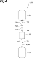
- a blood processing system 100 that includes the blood processing filter 1A is described (see FIG. 4 ).
- the blood processing filter 1A can be used for filtering using gravity.
- the blood processing system 100 to which the blood processing filter 1A is applied includes a reservoir bag 101 into which blood is filled after collection, the blood processing filter 1A, and a recovery bag 103 for accumulating blood after filtering.
- a preservative solution (priming fluid) for priming is previously inserted into the recovery bag 103.
- a preservative solution (priming fluid) for priming is previously inserted into the recovery bag 103
- a form may also be adopted in which a bag for a preservative solution is provided separately from the recovery bag 103, and priming is performed in a manner in which flow channels are appropriately switched.
- the reservoir bag 101 and the inlet port 9a of the blood processing filter 1A are connected to each other by a capillary tube 102a such as a blood tube.
- the recovery bag 103 and the outlet port 11 a of the blood processing filter 1A are connected to each other by a capillary tube 104a such as a blood tube.
- Opening/closing means 102b such as a roller clamp that opens and closes a flow channel, and a chamber 102c and the like are mounted to the capillary tube 102a on the upstream side.
- An inlet-side circuit 102 is formed by the capillary tube 102a, the opening/closing means 102b, and the chamber 102c and the like.
- An outlet-side circuit 104 is formed by the capillary tube 104a and the like on the downstream side.
- FIG. 5 and FIG. 6 a method for priming the blood processing filter 1A is described referring to FIG. 5 and FIG. 6 .
- a method for priming the blood processing filter 1A Prior to performing processing of blood in order to remove leukocytes or the like, it is necessary to extract air from inside the blood processing filter 1A and wet the filter element 5. Retro-priming is performed for this purpose.
- the blood processing filter 1A When performing retro-priming with respect to the blood processing filter 1A, the blood processing filter 1A is turned sideways in a state in which the outlet side faces downwards, and is set on a mounting face 110a of a substantially horizontal stand 110.
- the outlet port 11 a that protrudes from the outer surface 12a of the extension space forming part 12 of the second container forming part 11 is provided in the blood processing filter 1A. Consequently, when the blood processing filter 1A whose outlet side is facing downward is set on the mounting face 110a of the stand 110, the outlet port 11 a comes between the outer surface of the blood processing filter 1A and the mounting face 110a, and thus the blood processing filter 1A enters an inclined state (see FIG. 5 ).
- one portion of the surrounding space forming part 92 that encloses the filtration space forming part 91 in a ring shape is positioned above the filtration space forming part 91.
- the recovery bag 103 is arranged at a position that is above the blood processing filter 1A, the reservoir bag 101 is arranged at a position that is below the blood processing filter 1A (see FIG. 6(a) and FIG. 6(b) ), and the inlet-side circuit 102 and the outlet-side circuit 104 are opened.
- the preservative solution (priming fluid) for diluting the blood is inside the recovery bag 103, and when the recovery bag 103 is arranged at a higher position than the blood processing filter 1A the preservative solution inside the recovery bag 103 flows as far as the blood processing filter 1A through the capillary tube 104a, and passes through the outlet port 11 a and is filled into the filtration space S2 on the outlet side within the flexible container 3.
- the boundary surface of the preservative solution rises as the preservative solution is being filled, and as a result the air inside the flexible container 3 passes through the filter element 5 and is pushed out from the inlet port 9a to thereby remove air from the blood processing filter 1A.
- the outlet port 11 a is arranged inside the region Ar that overlaps with the filtration space forming part 91. That is, the outlet port 11a is arranged at a position that is comparatively near the center, and not the periphery, of the extension space forming part 12. Therefore the blood processing filter 1A inclines to a large degree. Accordingly, the escape of residual air into the air accumulating space S3 is promoted, and the suppression of an air block inside the filtration space S2 on the outlet side and the smooth removal of air are performed more efficiently.
- the preservative solution After air has been pushed out from inside the flexible container 3, the preservative solution passes through the inlet port 9a and flows out into the capillary tube 102a, and ultimately reaches the reservoir bag 101. Thus, the retro-priming ends.
- normal blood processing (a filtration process) for the purpose of removing leukocytes or the like is performed (see FIG. 6(c) ).
- the reservoir bag 101 into which blood is filled after collection is arranged at a position that is approximately 50 cm higher than the blood processing filter 1A
- the recovery bag 103 in which blood is accumulated after filtering is arranged at a position that is approximately 100 cm lower than the blood processing filter 1A.
- the blood filtering process is performed by opening the flow channel of the blood processing system 100.
- a negative pressure arises on the outlet side of the flexible container 3 of the blood processing filter 1A, and the second container forming part 11 deforms and adheres to the filter element 5.
- the valley part 6 is formed on the outlet side of the filter element 5, and the outer slanted face portion 6c (protruding nonwoven fabric portion 5c) of the valley part 6 comes between the filter element 5 and the second container forming part 11 so that adherence of the second container forming part 11 to the filter element 5 is partially restricted, and therefore the passage region Ps formed by the valley part 6 is maintained as a gap.
- an area surrounded by the inside seal part 13 of the filter element 5 functions as the effective filtering portion 5a of the filter element 5.
- the filtration space S1 on the inlet side of the flexible container 3 is a narrow space that substantially faces the effective filtering portion 5a
- the space on the outlet side is a wide space that includes not only the narrow filtration space S1 that faces the effective filtering portion 5a, but also the surrounding extended air accumulating space S3. Since the wide space side is the outlet side for blood, the occurrence of an air block due to a build-up of air bubbles at the surface on the outlet side of the filter element 5 can be prevented when priming the blood processing filter 1A, and the filter performance can be improved.
- FIG. 5 is a sectional view of the blood processing filter according to the present embodiment
- FIG. 7 is a sectional view of a blood processing filter according to a reference example.
- a blood processing filter 200 according to the reference example includes a sheet-like filter element 201, and a flexible container 202 whose internal space is divided into an inlet side and an outlet side by the filter element.
- the flexible container 202 has a first container forming part 203 and a second container forming part 204 that are arranged opposite each other so as to sandwich the filter element 201 therebetween.
- An inlet port 203a is provided in the first container forming part 203
- an outlet port 204a is provided in the second container forming part 204.
- the first container forming part 203 and the second container forming part 204 are integrated with the filter element 201 at both an inside seal part 210 and an outside seal part 211. That is, unlike the second container forming part 11 according to the present embodiment, in the second container forming part 204 according to the reference example, a filtration space S5 and a surrounding space S6 are clearly separated by the inside seal part 210.
- the valley part 6 that is partially recessed on the outlet side of the filter element 5 is formed in the blood processing filter 1A, there is an advantage at a time of normal filtration also. More specifically, since the valley part 6 is formed around the effective filtering portion 5a, the flow of blood to the valley part 6 as a blood flow channel from the filter element 5 on the outlet side spreads out and does not concentrate at one point. Accordingly, even if a dual force caused by a positive pressure on the inlet side and a negative pressure on the outlet side acts at the time of filtering, it is possible to avoid a situation in which the flow of blood is inhibited by adherence or the like between the second container forming part 11 and the filter element 5 and the filtering performance is lowered. This is advantageous in terms of effectively utilizing the entire filter element 5, and thus both a high filtering flow rate and high filtering performance can be achieved in a compatible manner.
- FIG. 8 is a sectional view of the blood processing filter according to the second embodiment of the present disclosure.
- a blood processing filter 1B according to the second embodiment includes substantially the same elements and structures as the blood processing filter 1A according to the first embodiment.
- elements and structures that are the same as in the first embodiment are denoted by the same reference symbols and a detailed description thereof is omitted, and the description centers on elements and structures that are different from those of the first embodiment.
- the blood processing filter 1B includes a flexible container 3 that has an inlet port 9a and an outlet port 11a for blood, a sheet-like filter element 5 that is arranged so as to divide an internal space of the flexible container 3 into an inlet port 9a side and an outlet port 11a side, and a welding sheet 31A that is arranged on the outlet side of the filter element 5 at a position that corresponds to a position at which the inside seal part 13 is formed.
- the flexible container 3 includes a first container forming part 9 having a rectangular sheet shape, and a second container forming part 11 having a rectangular sheet shape.
- the first container forming part 9 and the second container forming part 11 overlap with each other through the rectangular filter element 5.
- the first container forming part 9, the filter element 5, and the welding sheet 31A are sealed to each other and thereby integrated, and as a result a band-shaped inside seal part 13 is formed along the periphery of the filter element 5.
- the valley part 6 is formed in the filter element 5 by the inside seal part 13, and in a state in which blood is flowing (state at a time of use), a passage region Ps is formed between the valley part 6 and the second container forming part 11.
- a space on the outlet side is a wide space that includes not only a narrow filtration space S2 facing the effective filtering portion 5a, but also a surrounding extended air accumulating space S3. Since the wide space side is the outlet side for blood, the occurrence of an air block due to a build-up of air bubbles at the surface on the outlet side of the filter element 5 can be prevented when priming the blood processing filter 1B, and thus the filter performance can be improved.
- FIG. 9 is a sectional view of the blood processing filter according to the third embodiment of the present disclosure, and shows a state in which the blood processing filter is placed in an upright state to perform a normal filtration process.
- the substantial point of difference between a blood processing filter 1C according to the third embodiment and the blood processing filter 1A according to the first embodiment is that the positions of the inlet port and the outlet port are reversed.
- the following description centers on this point of difference, and elements and structures that are substantially the same as in the first embodiment are denoted by the same reference symbols and a detailed description thereof is omitted.
- the blood processing filter 1C includes a flexible container 3 that has an inlet port 11d and an outlet port 9d for blood, and a sheet-like filter element 5 that is arranged so as to divide an internal space of the flexible container 3 into one side and another side.
- the flexible container 3 includes a first container forming part 9 having a rectangular sheet shape, and a second container forming part 11 having a rectangular sheet shape.
- the outlet port 9d is formed in the first container forming part 9, and the inlet port 11d is formed in the second container forming part 11.
- the first container forming part 9 and the second container forming part 11 are arranged opposite each other so as to sandwich the filter element 5 therebetween.
- the outlet port 9d communicates with an internal space on the one side
- the inlet port 11d communicates with an internal space on the other side.
- the flexible container 3 has an annular inside seal part (first seal part) 13 and an annular outside seal part (second seal part) 15.
- the inside seal part (first seal part) 13 is formed so as to seal the first container forming part 9 and the filter element 5 in a band shape and surround the outlet port 9d provided in the first container forming part 9.
- the outside seal part (second seal part) 15 is formed so as to seal the first container forming part 9 and the second container forming part 11, and surround the inside seal part 13 along an outer edge of the second container forming part 11.
- the first container forming part 9 has an interior filtration space forming part 91 and an exterior surrounding space forming part 92 that are separated by the inside seal part 13.
- the second container forming part 11 has an extension space forming part 12 that is surrounded by the outside seal part 15, and is arranged opposite the filter element 5 and the surrounding space forming part 92 without being divided by the inside seal part 13.
- the inlet port 11d of the second container forming part 11 is provided in the extension space forming part 12, and protrudes further than an outer surface 12a of the extension space forming part 12.
- an area surrounded by the inside seal part 13 of the filter element 5 functions as an effective filtering portion 5a of the filter element 5.
- a filtration space S11 on the outlet side of the flexible container 3 is a narrow space that substantially faces the effective filtering portion 5a
- a space on the inlet side is a wide space that includes not only a narrow filtration space S12 that faces the effective filtering portion 5a, but also a surrounding extended surplus space S 13.
- the wide space side is the inlet side for blood, for example, even if aggregates or air bubbles enter during filtration, the aggregates or air bubbles escape into the surrounding surplus space S13 that is located away from the effective filtering portion 5a, and thus blocking of the filter element 5 can be suppressed and filter performance can be improved.
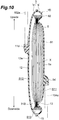
- FIG. 10 is a sectional view of the blood processing filter according to the fourth embodiment of the present disclosure, and shows a state in which the blood processing filter is placed in an upright state to perform a normal filtration process.
- a blood processing filter 1D according to the fourth embodiment includes substantially the same elements and structures as the blood processing filter 1C according to the third embodiment.
- elements and structures that are the same as in the third embodiment are denoted by the same reference symbols and a detailed description thereof is omitted, and the description centers on elements and structures that are different from those of the third embodiment.
- the blood processing filter ID includes a welding sheet 31B that is arranged on an inlet side of a filter element 5 at a position corresponding to a position at which an inside seal part 13 is formed.
- a first container forming part 9 and a second container forming part 11 overlap with each other so as to sandwich the rectangular filter element 5.
- the first container forming part 9, the filter element 5, and the welding sheet 31B are sealed to each other and thereby integrated, and as a result the band-shaped inside seal part 13 is formed along the periphery of the filter element 5.
- a valley part 6 is formed in the filter element 5 by the inside seal part 13, and in a state in which blood is flowing (state at a time of use), a passage region Ps is formed between the valley part 6 and the second container forming part 11.
- an area surrounded by the inside seal part 13 of the filter element 5 functions as an effective filtering portion 5a of the filter element 5.
- a filtration space S11 on the outlet side of the flexible container 3 is a narrow space that substantially faces the effective filtering portion 5a
- a space on the inlet side is a wide space that includes not only a narrow filtration space S12 that faces the effective filtering portion 5a, but also a surrounding extended surplus space S 13.
- the wide space side is the inlet side for blood, for example, even if aggregates or air bubbles enter during filtration, the aggregates or air bubbles escape into the surrounding surplus space S13 that is located away from the effective filtering portion 5a, and thus blocking of the filter element 5 can be suppressed and filter performance can be improved.
- a blood processing filter including a filter element and a flexible container having a container forming part on an inlet side (first container forming part) and a container forming part on an outlet side (second container forming part) was prepared, and an inlet port thereof was connected to a reservoir bag via an inlet-side circuit having a length of 50 cm.
- An outlet port of the filter was connected to a recovery bag including 100 mL of red cell preservative solution (SAG-M) via an outlet-side circuit having a length of 100 cm.
- SAG-M red cell preservative solution
- a tube made of soft polyvinyl chloride having an internal diameter of 2.9 mm and an external diameter of 4.2 mm was used for the inlet-side circuit and the outlet-side circuit.
- an effective filtering portion was formed in a rectangular shape in which an inner side of a first seal part had a longitudinal dimension of 74 cm and a horizontal dimension of 57 cm, a corner portion was formed as a curve, and an effective filtration area of 42x 10 -4 (m 2 ) was provided.
- the filter element As the filter element, four sheets of polyester nonwoven fabric having an air permeability of 237.3 (cm 3 /cm 2 /sec) and a thickness of 0.2 mm, one sheet of polyester nonwoven fabric having an air permeability of 8.4 (cm 3 /cm 2 /sec) and a thickness of 0.4 mm, 32 sheets of polyester nonwoven fabric having an air permeability of 7.7 (cm 3 /cm 2 /sec) and a thickness of 0.20 mm, one sheet of nonwoven polyester fabric having an air permeability of 8.4 (cm 3 /cm 2 /sec) and a thickness of 0.4 mm, and four sheets of nonwoven polyester fabric having an air permeability of 237.3 (cm 3 /cm 2 /sec) and a thickness of 0.2 mm were stacked in that order from the inlet to the outlet at the time of filtering blood, and used.
- the air permeability was measured by a method based on Japanese Industrial Standard JIS L-1096, 6.2
- the two ports serving as the inlet and the outlet were sealed in separate container forming parts, respectively.
- the first seal part was formed by disposing one of the container forming parts and the filter element in a layered arrangement. Thereafter, the other container forming part was arranged so as to sandwich the filter element between the two container forming parts, and the peripheries of the two container forming parts were caused to overlap with each other to form the second seal part. At that time, sealing and assembly were performed so as to dispose the openings of the respective ports at positions on the inner side of the filtering part which were 2.4 cm from an end on the effective filtering portion side of a short side portion of the rectangular-shaped first seal part.
- the port provided in the container forming part welded to the filter element at the first seal part was taken as the inlet side port and connected to a circuit (inlet-side circuit) on the side that was connected to the reservoir bag.
- the port on the opposite side was taken as the outlet side port and connected to a circuit (outlet-side circuit) on the side that was connected to the recovery bag.
- the recovery bag was suspended so that a drop from a circuit connection part of the recovery bag to the horizontally placed blood processing filter was 50 cm, the blood processing filter and the reservoir bag were placed on a table, and the filter was primed with the red cell preservative solution.
- the port on the side serving as an inlet for the red cell preservative solution was arranged on the bottom side so as to contact the table.
- the reservoir bag including the red cell preservative solution used for priming was exchanged for another reservoir bag including a liquid to be processed (a blood substitute) and a sterile connecting device. At that time, the length of the circuit was maintained without change.
- liquid to be processed blood substitute
- 300 g of an aqueous solution of polyvinyl pyrrolidone (weight average molecular weight: 360,000) adjusted to a viscosity of 17 mPa ⁇ s (25°C) and pH 3.8 was used at room temperature.
- the total drop from the reservoir bag to the recovery bag was fixed at 150 cm.
- the recovery bag was placed in advance on a scale balance to enable verification of changes in the weight thereof, and the liquid to be processed was filtered using gravity.
- Filtering was carried out using a filter assembled by the same method as in Example 1, except that a first seal part was formed by sandwiching a filter element between two container forming parts, and thereafter a second seal part was formed by sandwiching the filter element between two container forming parts.
- Table 1 shows the results for Example 1 and Comparative Example 1. [Table 1] Example 1 Comparative Example 1 Total Processing Time (min) Number of Tests 10 10 Mean 26.3 32.2 Standard Deviation 1.5 11.6
- the total drop from the reservoir bag to the recovery bag was fixed at 150 cm.
- the recovery bag was placed in advance on a scale balance to enable verification of changes in the weight thereof, and the liquid to be processed was filtered using gravity.
- the liquid to be processed was obtained by adding 70 mL of anticoagulant solution (CPD-A) to 500 mL of pig whole blood and mixing, and thereafter storing the resulting product in a flexible container at 4°C for three days before use. After taking the liquid to be processed out from a cooling box, blood cell components and liquid components that had separated during storage were mixed by inversion, and thereafter filtration was carried out forthwith.
- CPD-A anticoagulant solution
- Filtering was carried out using a filter assembled by the same method as in Example 2, except that a first seal part was formed by sandwiching a filter element between two container forming parts, and thereafter a second seal part was formed by sandwiching the filter element between two container forming parts.
- Example 2 shows the results for Example 2 and Comparative Example 2.
- Example 2 Comparative Example 2 Total Processing Time (min) Number of Tests 10 10 Mean 44.3 63.1 Standard Deviation 4.1 31.1
Description
- The present invention relates to a method for primping a blood processing filter for removing undesirable components such as aggregates and leukocytes from blood. In particular, the present invention relates to a method for priming a precise and disposable blood processing filter for removing microaggregates and leukocytes which may cause side effects from whole blood preparations, erythrocyte preparations, thrombocyte preparations, blood plasma preparations and the like for blood transfusion.
- It is becoming common for whole blood collected from a donor to be separated into blood component preparations such as an erythrocyte preparation, a thrombocyte preparation, and a blood plasma preparation and stored for transfusion. Since microaggregates and leukocytes included in these blood preparations cause various side effects during blood transfusion, the number of occasions for removing these undesirable components before blood transfusion has been increasing. The need for leukocyte removal has widely been recognized particularly in recent years. Legislation regarding removal of leukocytes from all kinds of blood preparations for blood transfusion before being used for transfusion has been introduced in an increasing number of countries.
- The most common method of removing leukocytes from blood preparations is by processing blood preparations using a leukocyte removal filter. Conventionally, in many cases blood preparations processed using a leukocyte removal filter have been processed at the bedside when blood transfusion is performed. In recent years, however, to improve quality control of leukocyte-free preparations and efficiency of leukocyte removal operations, it is more common, particularly in developed countries, to process the blood preparations in blood centers before storing the blood preparations. Hereinafter, a leukocyte removal performed before storage is referred to as a "pre-storage leukocyte removal".
- A blood collection-separation set, typically consisting of two to four flexible bags, a tube connecting these bags, an anticoagulant, an erythrocyte preservation solution, a blood collection needle, and the like has been used for collecting blood from a donor, separating the blood into several blood components, and storing the blood components. A system in which a leukocyte removal filter is incorporated into such a blood collection-separation set has been widely used as an optimum system for the above-mentioned "pre-storage leukocyte removal". Such a system is called a "closed system" or an "integrated system" or the like. Such systems are disclosed in Japanese Patent Laid-Open No.
1-320064 WO 92/020428 - Conventionally, a filter element made from nonwoven fabric or a porous body packed in a hard container of polycarbonate or the like has been widely used as a leukocyte removal filter. However, because, in case of the hard container, the container has a low level of air permeability, there is the problem that it is difficult to apply steam sterilization, which is widely used as a sterilization process in blood collection-separation sets. In one type of closed system, leukocytes are first removed from the whole blood preparation after collecting the blood. Subsequently, after the leukocyte removal filter is separated, the leukocyte-free blood is centrifuged for separation into various components. In another type of closed system, the whole blood is first centrifuged to be divided into various blood components, and then the leukocytes are removed. In the latter system, the leukocyte removal filter is also centrifuged together with the blood collection-separation set. At such time, a hard container may damage bags and tubes, or the hard container itself may not withstand the stress and may break during centrifugation.
- To solve these problems, flexible leukocyte removal filters have been developed in which the container is made of a material having excellent flexibility and steam permeability that is the same as or similar to the material used for the bags of the blood collection-separation set, and in fact blood processing filters in which a flexible container is directly welded to a filter element and the like are known (see Japanese Patent Laid-Open No.
7-267871 WO 95/017236
US 2004/0251195 discloses a flexible blood filter allowing smooth flow of a liquid and being excellent in separation resistance, pressure resistance and centrifugation resistance. The blood processing filter, includes a first filter element for removing aggregates from blood, a second filter element for removing leukocytes provided in the downstream of the first filter element, and a third filter element having gas permeability of 3 to 40 cm-3/cm2/sec per thickness of 1 cm provided between the second filter element and the outlet port. The blood processing filter is primed by squeezing the blood containing brood bag in order to remove the air contained in the filter bag. -
- Patent Document 1: Japanese Patent Laid-Open No.
01-320064 - Patent Document 2: International Publication No.
WO 92/020428 - Patent Document 3: Japanese Patent Laid-Open No.
07-267871 - Patent Document 6: International Publication No.
WO 95/017236 - However, according to the conventional leukocyte removal filter, in many cases the one side and the other side into which the flexible container is divided by the filter element are substantially the same shape and have the same capacity, and it can not be said that sufficient consideration has been given to filter performance in relation to suppressing blockage of the filter element that results from the interrelationship between the one side and the other side of the flexible interrelationship between the one side and the other side of the flexible container and to preventing an air block occurring when priming and the like.
- An object of the present invention is to provide a method for priming a blood processing filter that can improve the filter performance.
- More specifically, according to the present invention, there is provided a method for priming a blood processing filter comprising a sheet-like filter element, and a flexible container having an internal space that is divided into one side and another side by the filter element,
the flexible container comprising: a first container forming part and a second container forming part that are arranged opposite each other so as to sandwich the filter element therebetween, an inlet port that is provided in the first container forming part and that serves as an inlet for blood, an outlet port that is provided in the second container forming part and that serves as an outlet for blood, a band-shaped annular first seal part that seals the first container forming part and the filter element and that is formed so as to surround the inlet port, and an annular second seal part that seals at least the first container forming part and the second container forming part and that is formed so as to surround the first seal part along an outer edge of the second container forming part;
wherein: the first container forming part has an interior filtration space forming part and an exterior surrounding space forming part that are separated by the first seal part, and the second container forming part has an extension space forming part that is surrounded by the second seal part and is arranged opposite the filter element and the surrounding space forming part; and
the inlet port is provided in the filtration space forming part and communicates with an internal space on the one side that is defined by the filter element, and the outlet port is provided in the extension space forming part and communicates with an internal space on the other side that is defined by the filter element and protrudes further than an outer surface of the extension space forming part;
the method being characterized in that the extension space forming part is not divided by the first seal part, and by
turning the blood processing filter sideways with the outlet port facing downwards, and setting the blood processing filter on a mounting face in a state in which blood processing filter is inclined with respect to the mounting face; and
filling a priming fluid from the outlet port of the blood processing filter that is set on the mounting face to remove air from inside the blood processing filter. - Preferred embodiments of the invention are apparent from the dependent claims.
- Also disclosed is a blood processing filter that includes a sheet-like filter element, and a flexible container having an internal space that is divided into one side and another side by the filter element; the flexible container including: a first container-forming part and a second container-forming part that are arranged opposite each other so as to sandwich the filter element therebetween; ports provided in the first container forming part and the second container forming part, respectively, that serve as an inlet or an outlet for blood; a band-shaped annular first seal part that seals the first container forming part and the filter element in a band shape, and that is formed so as to surround the port provided in the first container forming part; and an annular second seal part that seals at least the first container forming part and the second container forming part, and that is formed so as to surround the first seal part along an outer edge of the second container forming part; wherein: the first container forming part has an interior filtration space forming part and an exterior surrounding space forming part that are separated by the first seal part; the second container forming part has an extension space forming part that is surrounded by the second seal part and is arranged opposite the filter element and the surrounding space forming part, without being divided by the first seal part; the port of the first container forming part is provided in the filtration space forming part and communicates with an internal space on the one side that is defined by the filter element; and the port of the second container forming part is provided in the extension space forming part and communicates with an internal space on the other side that is defined by the filter element, and protrudes further than an outer surface of the extension space forming part. In this connection, in the present invention the term "blood" includes blood preparations such as whole blood preparations, erythrocyte preparations, thrombocyte preparations, and blood plasma preparations for blood transfusion.
- In the above described blood processing filter, an area surrounded by the first seal part of the filter element functions as an effective filtering portion of the filter element. Further, with respect to the internal space of the flexible container, a space on one side is a narrow space that substantially faces the effective filtering portion, and a space on the other side is a wide space that includes not only a narrow space that faces the effective filtering portion but also a surrounding extended space. Accordingly, when the blood processing filter is used so that the wide space side serves as an outlet side for blood, for example, it is possible to prevent an air block occurring due to a build-up of air bubbles at the surface on the outlet side of the filter element when priming the filter, and thereby improve the filter performance. Further, when the blood processing filter is used so that the wide space side serves as an inlet side for blood, for example, even if aggregates or air bubbles enter during filtration, the aggregates or air bubbles escape to the surrounding extended space that is located away from the effective filtering portion, and thus blockage of the filter element can be suppressed and filter performance can be improved.
- Also disclosed is a blood processing filter according to the above described blood processing filter, in which the port of the first container forming part is an inlet port that serves as an inlet for blood, and the port of the second container forming part is an outlet port that serves as an outlet for blood.
- When performing priming with respect to the above described blood processing filter, the blood processing filter is set on a mounting face in a state in which the outlet side is facing downward. Since the outlet port that protrudes from the outer surface of the extension space forming part is provided in the blood processing filter, when the blood processing filter is set on the mounting face in a state in which the outlet side is facing downward, the outlet port comes between the outer surface and the mounting face, and the blood processing filter enters an inclined state. As a result, a portion of a surrounding space forming part that encloses the filtration space forming part in an annular shape is positioned at a higher position than the filtration space forming part. Next, a priming fluid is filled from the outlet port of the blood processing filter. The boundary surface of the priming fluid rises as the priming fluid is filled, and as a result the air on the outlet side passes through the filter element and is pushed out from the inlet port. At this time, some air remains inside the space on the outlet side of the filter element. However, since a space for accumulating air that is formed by the surrounding space forming part exists in an upper part on the outlet side, the residual air escapes into the space for accumulating air, and thus the occurrence of an air block inside the space on the outlet side that corresponds to the filtration space forming part can be suppressed and removal of air can be performed smoothly.
- Further disclosed is a blood processing filter according to the above described blood processing filter, in which the port of the first container forming part is an outlet port that serves as an outlet for blood, and the port of the second container forming part is an inlet port that serves as an inlet for blood.
- According to this blood processing filter, for example, even when blood with respect to which generation of aggregates is a concern is processed, such as when the blood has been stored in refrigerated storage for a fixed period of time, since a wide space is formed on the inlet side, the possibility of aggregates and the like attaching to the filter element and blocking the filter element can be reduced.
- The present disclosure also provides a blood processing filter according to the above described blood processing filter, in which, the outlet port is arranged in a region of the extension space forming part that overlaps with the filtration space forming part.
- Further, the present disclosure provides a blood processing filter according to the above described blood processing filter, in which the inlet port and the outlet port are point symmetric.
- According to the present invention, it is possible to improve the filter performance.
-
-
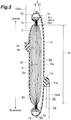
FIG. 1 is a plan view that illustrates one portion of a blood processing filter according to a first embodiment of the present disclosure, that is shown in a cut-away manner; -
FIG. 2 is a sectional view taken along a line II-II inFIG. 1 ; -
FIG. 3 is a sectional view taken along a line III-III inFIG. 1 ; -
FIG. 4 is a front view that shows an outline of a blood processing system that includes the blood processing filter according to the first embodiment; -
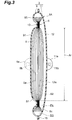
FIG. 5 is a sectional view that illustrates a state in which retro-priming is being performed with respect to the blood processing filter according to the first embodiment; -
FIG. 6 is a view that schematically illustrates procedures in which retro-priming is performed with respect to a blood processing filter, and thereafter a filtration process is performed, in which: (a) is a view that illustrates a state in which retro-priming is being performed, (b) is a view that illustrates a state in which retro-priming is completed, and (c) is a view that illustrates an initial state after transitioning to the filtration process; -
FIG. 7 is a sectional view of a reference example of a blood processing filter, that illustrates a state in which retro-priming is being performed with respect to the blood processing filter according to the reference example; -
FIG. 8 is a sectional view of a blood processing filter according to a second embodiment; -
FIG. 9 is a sectional view of a blood processing filter according to a third embodiment; and -
FIG. 10 is a sectional view of a blood processing filter according to a fourth embodiment. - Embodiments of the present invention are described hereunder with reference to the drawings. Note that the term "blood" that is described in the following embodiments includes blood preparations such as whole blood preparations, erythrocyte preparations, thrombocyte preparations and blood plasma preparations for blood transfusion. Further, although various forms can be adopted for the external shape of the blood processing filter, such as a rectangular shape, a disc shape, an oval disc shape, and an elliptical shape, a rectangular shape is preferable for decreasing loss of materials when the filters are manufactured. Accordingly, in the following embodiments, an example in which the blood processing filter has a rectangular shape is described.
- First, a
blood processing filter 1A according to a first embodiment of the present disclosure is described referring toFIGS. 1 to 3 . Theblood processing filter 1A includes aflexible container 3 having aninlet port 9a and anoutlet port 11a for blood, and a sheet-like filter element 5 that is arranged so as to divide an internal space of theflexible container 3 into one side and another side. Theinlet port 9a communicates with an internal space on the one side of theflexible container 3 whose internal space is divided into two sides by thefilter element 5, and theoutlet port 11a communicates with an internal space on the other side of theflexible container 3. Theinlet port 9a and theoutlet port 11a are arranged so that, when the approximate center of thefilter element 5 is defined as a hypothetical point X, theinlet port 9a and theoutlet port 11 a are point symmetric about the hypothetical point X as the center. - The
flexible container 3 has a rectangular, flat shape. Here, the term "flat shape" means a shape having a thin thickness and a wide surface. Theflexible container 3 includes a firstcontainer forming part 9 that has a rectangular sheet shape, and a secondcontainer forming part 11 that has a rectangular sheet shape. The firstcontainer forming part 9 and the secondcontainer forming part 11 are arranged opposite each other so as to sandwich thefilter element 5 therebetween. - An
inlet port 9a in which aninlet flow channel 9b that allows the inside and the outside to communicate is formed is sealed in the firstcontainer forming part 9. Theinlet port 9a is an inlet through which pre-processing blood is accepted into the internal space of theflexible container 3. Anoutlet port 11 a in which anoutlet flow channel 11b that allows the inside and the outside to communicate is formed is sealed in the secondcontainer forming part 11. Theoutlet port 11a is an outlet through which processed blood is discharged from theflexible container 3. In this connection, as used herein, the term "seal (to seal)" refers to fixing by bonding (including welding) to a degree that can prevent leakage of a liquid. - The first
container forming part 9 is sealed along the periphery of thefilter element 5 in a state in which the firstcontainer forming part 9 is adhered to thefilter element 5. An area that is sealed in a band shape along the periphery of thefilter element 5 is aninside seal part 13. Theinside seal part 13 surrounds theinlet port 9a in a rectangular ring shape. - The first
container forming part 9 is divided into an inner side that is surrounded by theinside seal part 13, and an outer side that encloses theinside seal part 13. An area located at a position that is further on the inner side than theinside seal part 13 is a filtrationspace forming part 91. Theinlet port 9a is provided in the filtrationspace forming part 91. A filtration space S1 through which blood that has flown out from theinlet port 9a flows is formed between the filtrationspace forming part 91 and thefilter element 5. A portion of thefilter element 5 that faces the filtration space S1 is aneffective filtering portion 5a. Theinside seal part 13 corresponds to a first seal part. In this connection, a protrudingnonwoven fabric portion 5c that is a surplus portion of thefilter element 5 protrudes to the outside of theinside seal part 13. - The periphery of the first
container forming part 9 overlaps with the periphery of the secondcontainer forming part 11, and the peripheries adhere with each other and are sealed in a band shape. An area that is sealed along the peripheries of the firstcontainer forming part 9 and the secondcontainer forming part 11 is anoutside seal part 15 that surrounds theinside seal part 13 in a rectangular ring shape. An approximately donut-shaped area formed between theinside seal part 13 and theoutside seal part 15 is a surroundingspace forming part 92. Theoutside seal part 15 corresponds to a second seal part. - A rectangular ring-shaped recess that corresponds to the rectangular ring-shaped inside
seal part 13 is formed on the outlet side of thefilter element 5. This recess is formed as a result of thefilter element 5 being integrated with the firstcontainer forming part 9 in a state in which thefilter element 5 is compressed from both sides accompanying formation of theinside seal part 13. This recess is avalley part 6 that is provided on the outlet side of thefilter element 5. - The
valley part 6 will now be described in further detail (seeFIG. 2 ). Thefilter element 5 that is formed by stacking a plurality of nonwoven fabrics or the like has a constant thickness, and in a state in which sealing such as welding has not been performed, the surface of thefilter element 5 is in a flat state. Subsequently, for example, if the two faces of thefilter element 5 are sandwiched with a PVC sheet and high frequency welding is performed, the welded place is crushed and integrated, and the integrated place is thin in comparison to the original thickness of thefilter element 5. - According to the
filter element 5 of the present embodiment, for example, a process for sealing, such as high frequency welding, is carried out using a predetermined mold to form theinside seal part 13, and as a result an integrated place is formed in a ring shape. The places other than the integrated place are still substantially flat over the entire area of thefilter element 5 after the process for sealing has been carried out, and only the vicinity of the integrated place is different. For example, when attention is focused on the outlet side of thefilter element 5, it is seen that the integrated place is abottom part 6a that is the most recessed area, and areas adjoining the integrated place are slantedface portions bottom part 6a. More specifically, thevalley part 6 has thebottom part 6a that overlaps with theinside seal part 13, the inner slantedface portion 6b that rises towards the inner side of theinside seal part 13 from thebottom part 6a, and the outerslanted face portion 6c that rises towards the outer side of theinside seal part 13 from thebottom part 6a. - Although the second
container forming part 11 is integrated with the firstcontainer forming part 9 through theoutside seal part 15, the secondcontainer forming part 11 is not bonded to thefilter element 5, and in an at-rest state the secondcontainer forming part 11 enters a state in which the secondcontainer forming part 11 is roughly separated from thevalley part 6 of thefilter element 5. More specifically, the secondcontainer forming part 11 has an extensionspace forming part 12 that is arranged so that an area facing thefilter element 5 and an area facing the surroundingspace forming part 92 of the firstcontainer forming part 9 are formed in a continuous manner without being separated by theinside seal part 13. - A filtration space S2 is formed on the outlet side between the extension
space forming part 12 and thefilter element 5, and an air accumulating space S3 to which air escapes during priming is formed between the extensionspace forming part 12 and the surroundingspace forming part 92. There is no partition between the filtration space S2 on the outlet side and the air accumulating space S3, and therefore the filtration space S2 and the air accumulating space S3 communicate with each other. - The
outlet port 11a is provided in the extensionspace forming part 12 of the secondcontainer forming part 11, and protrudes further than anouter surface 12a of the extensionspace forming part 12. In particular, theoutlet port 11a according to the present embodiment is arranged in a region Ar of the extensionspace forming part 12. The region Ar overlaps with the filtrationspace forming part 91 of the firstcontainer forming part 9. - Next, forms of the material and shape and the like of each element constituting the
blood processing filter 1A are described. As described in the foregoing, theflexible container 3 is formed by the firstcontainer forming part 9 and the secondcontainer forming part 11. Any material that is commercially available as a sheet or a film can be used as a flexible resin that is used for theflexible container 3. For example, thermoplastic elastomers such as soft polyvinyl chloride, polyurethane, ethylene-vinyl acetate copolymer, polyolefin such as polyethylene and polypropylene, hydrogenated styrene-butadienestyrene copolymer, styrene-isoprene-styrene copolymer, and hydrogenated products thereof, mixtures of the thermoplastic elastomer and a softening agent such as polyolefin and ethylene-ethyl acrylate, and the like may be mentioned as favorable materials. Since it can be considered that the material will contact with blood, preferable materials are soft polyvinyl chloride, polyurethane, and polyolefin that are used as the material of medical products such as blood bags, as well as thermoplastic elastomers containing these materials as main components, and more preferably the material is soft polyvinyl chloride. - Further, for example, a container described in Japanese Patent Laid-Open No.
7-267871 WO 95/017236 flexible container 3. - The
filter element 5 is manufactured using a filter material constituted by a fibrous integrated body such as nonwoven fabric or woven fabric or by a porous body such as sponge. Thefilter element 5 according to the present embodiment may be coated with a hydrophilic polymer to make it easier for blood to wet the filter material. Further, to facilitate attachment of leukocytes to thefilter element 5 when using theblood processing filter 1A to remove leukocytes from blood, a filter material that is coated with a polymer may be used. - Next, a method for manufacturing the
blood processing filter 1A according to the present embodiment is described. According to this manufacturing method, for example, the firstcontainer forming part 9 in which theinlet port 9a has been sealed at a predetermined position, the secondcontainer forming part 11 in which theoutlet port 11 a has been sealed at a predetermined position, and thefilter element 5 are prepared, and an installing step is performed in which the firstcontainer forming part 9 and the secondcontainer forming part 11 are arranged at predetermined positions so as to sandwich thefilter element 5. - After the installing step, a first sealing step and a second sealing step are performed without sealing the
filter element 5 and the secondcontainer forming part 11. In the first sealing step, theinside seal part 13 is formed by sealing the firstcontainer forming part 9 and thefilter element 5 in a band shape so as to surround the area in which theinlet port 9a is formed. In the second sealing step, the annular outside seal part (second seal part) 15 is formed by sealing the peripheries of the firstcontainer forming part 9 and the secondcontainer forming part 11 together in a band shape so as to surround theinside seal part 13. - In the first sealing step, the
valley part 6 that has a band shape that corresponds to theinside seal part 13 is generated on the outlet side of thefilter element 5. A passage region Ps is formed between the secondcontainer forming part 11 and thefilter element 5 by thevalley part 6. An inner area that is surrounded by the passage region Ps serves as the filtration space S2 on the outlet side, and an outer area serves as the air accumulating space S3. - Although formation of the
inside seal part 13 in the first sealing step, more specifically, sealing of the firstcontainer forming part 9 and thefilter element 5 can be performed utilizing high frequency welding, the present invention is not limited thereto, and various kinds of bonding techniques, such as ultrasonic welding and thermal welding, can be used. - Likewise, although formation of the
outside seal part 15 in the second sealing step, more specifically, sealing of the firstcontainer forming part 9 and the secondcontainer forming part 11 can be performed utilizing high frequency welding, the present invention is not limited thereto, and various kinds of bonding techniques, such as ultrasonic welding and thermal welding, can be used. - According to the above described manufacturing method, a form is described in which the
inlet port 9a is previously sealed to the firstcontainer forming part 9, and theoutlet port 11 a is previously sealed to the secondcontainer forming part 11. However, sealing may be performed after forming theinside seal part 13 or theoutside seal part 15, or may be performed during the process of forming theinside seal part 13 or theoutside seal part 15. Further, a method of sealing theinlet port 9a as a blood inlet and theoutlet port 11a as a blood outlet to theflexible container 3 is not limited to high frequency welding, and various kinds of bonding techniques, such as thermal welding, can be used. Similarly to theflexible container 3, various known materials can be used as the material of theinlet port 9a and theoutlet port 11a. - According to the above described manufacturing method, since the second
container forming part 11 is not integrated with thefilter element 5 at theinside seal part 13, that is, since the secondcontainer forming part 11 is not sealed to thefilter element 5, there is the advantage that arrangement of theoutlet port 11 a in the step of sealing theoutlet port 11 a to the secondcontainer forming part 11 can be performed with a comparatively high degree of freedom. More specifically, sealing of theinlet port 9a and theoutlet port 11 a inside theflexible container 3 is an advantage of the process of manufacturing the container welding typeblood processing filter 1A in which forming theinside seal part 13 and theoutside seal part 15 by a simple step is a feature, and by adopting a configuration in which theinside seal part 13 does not seal the secondcontainer forming part 11 it is possible to provide an even greater degree of freedom with respect to arrangement of theoutlet port 11 a. - Next, a
blood processing system 100 that includes theblood processing filter 1A is described (seeFIG. 4 ). - The
blood processing filter 1A can be used for filtering using gravity. For example, theblood processing system 100 to which theblood processing filter 1A is applied includes areservoir bag 101 into which blood is filled after collection, theblood processing filter 1A, and arecovery bag 103 for accumulating blood after filtering. A preservative solution (priming fluid) for priming is previously inserted into therecovery bag 103. In this connection, although an example in which a preservative solution (priming fluid) for priming is previously inserted into therecovery bag 103 is described according to the present embodiment, a form may also be adopted in which a bag for a preservative solution is provided separately from therecovery bag 103, and priming is performed in a manner in which flow channels are appropriately switched. - The
reservoir bag 101 and theinlet port 9a of theblood processing filter 1A are connected to each other by acapillary tube 102a such as a blood tube. Therecovery bag 103 and theoutlet port 11 a of theblood processing filter 1A are connected to each other by acapillary tube 104a such as a blood tube. Opening/closing means 102b such as a roller clamp that opens and closes a flow channel, and achamber 102c and the like are mounted to thecapillary tube 102a on the upstream side. An inlet-side circuit 102 is formed by thecapillary tube 102a, the opening/closing means 102b, and thechamber 102c and the like. An outlet-side circuit 104 is formed by thecapillary tube 104a and the like on the downstream side. - Next, a method for priming the
blood processing filter 1A is described referring toFIG. 5 andFIG. 6 . Prior to performing processing of blood in order to remove leukocytes or the like, it is necessary to extract air from inside theblood processing filter 1A and wet thefilter element 5. Retro-priming is performed for this purpose. - When performing retro-priming with respect to the
blood processing filter 1A, theblood processing filter 1A is turned sideways in a state in which the outlet side faces downwards, and is set on a mountingface 110a of a substantiallyhorizontal stand 110. Theoutlet port 11 a that protrudes from theouter surface 12a of the extensionspace forming part 12 of the secondcontainer forming part 11 is provided in theblood processing filter 1A. Consequently, when theblood processing filter 1A whose outlet side is facing downward is set on the mountingface 110a of thestand 110, theoutlet port 11 a comes between the outer surface of theblood processing filter 1A and the mountingface 110a, and thus theblood processing filter 1A enters an inclined state (seeFIG. 5 ). As a result, one portion of the surroundingspace forming part 92 that encloses the filtrationspace forming part 91 in a ring shape is positioned above the filtrationspace forming part 91. - Next, the
recovery bag 103 is arranged at a position that is above theblood processing filter 1A, thereservoir bag 101 is arranged at a position that is below theblood processing filter 1A (seeFIG. 6(a) and FIG. 6(b) ), and the inlet-side circuit 102 and the outlet-side circuit 104 are opened. The preservative solution (priming fluid) for diluting the blood is inside therecovery bag 103, and when therecovery bag 103 is arranged at a higher position than theblood processing filter 1A the preservative solution inside therecovery bag 103 flows as far as theblood processing filter 1A through thecapillary tube 104a, and passes through theoutlet port 11 a and is filled into the filtration space S2 on the outlet side within theflexible container 3. The boundary surface of the preservative solution rises as the preservative solution is being filled, and as a result the air inside theflexible container 3 passes through thefilter element 5 and is pushed out from theinlet port 9a to thereby remove air from theblood processing filter 1A. - When air is pushed out from the
inlet port 9a as described above, some air also stays behind in a space on the outlet side of thefilter element 5. However, because the air accumulating space S3 exists above the filtration space S2 on the outlet side, the residual air escapes into the air accumulating space S3, and therefore the occurrence of air block in the filtration space S2 on the outlet side can be suppressed and removal of air can be performed smoothly. - In particular, in the
blood processing filter 1A according to the present embodiment, theoutlet port 11 a is arranged inside the region Ar that overlaps with the filtrationspace forming part 91. That is, theoutlet port 11a is arranged at a position that is comparatively near the center, and not the periphery, of the extensionspace forming part 12. Therefore theblood processing filter 1A inclines to a large degree. Accordingly, the escape of residual air into the air accumulating space S3 is promoted, and the suppression of an air block inside the filtration space S2 on the outlet side and the smooth removal of air are performed more efficiently. - After air has been pushed out from inside the
flexible container 3, the preservative solution passes through theinlet port 9a and flows out into thecapillary tube 102a, and ultimately reaches thereservoir bag 101. Thus, the retro-priming ends. - After the end of retro-priming, normal blood processing (a filtration process) for the purpose of removing leukocytes or the like is performed (see
FIG. 6(c) ). In the case of normal blood processing, thereservoir bag 101 into which blood is filled after collection is arranged at a position that is approximately 50 cm higher than theblood processing filter 1A, and therecovery bag 103 in which blood is accumulated after filtering is arranged at a position that is approximately 100 cm lower than theblood processing filter 1A. - The blood filtering process is performed by opening the flow channel of the
blood processing system 100. When performing a filtering process (at a time of use), a negative pressure arises on the outlet side of theflexible container 3 of theblood processing filter 1A, and the secondcontainer forming part 11 deforms and adheres to thefilter element 5. However, thevalley part 6 is formed on the outlet side of thefilter element 5, and the outerslanted face portion 6c (protrudingnonwoven fabric portion 5c) of thevalley part 6 comes between thefilter element 5 and the secondcontainer forming part 11 so that adherence of the secondcontainer forming part 11 to thefilter element 5 is partially restricted, and therefore the passage region Ps formed by thevalley part 6 is maintained as a gap. As a result, it is difficult for the blood flow channel to be blocked, and it is easy to stably maintain the blood flow channel on the outlet side of theblood processing filter 1A. - Next, the actions and effects of the
blood processing filter 1A according to the present embodiment are described. In the case of theblood processing filter 1A, an area surrounded by theinside seal part 13 of thefilter element 5 functions as theeffective filtering portion 5a of thefilter element 5. Further, although the filtration space S1 on the inlet side of theflexible container 3 is a narrow space that substantially faces theeffective filtering portion 5a, the space on the outlet side is a wide space that includes not only the narrow filtration space S1 that faces theeffective filtering portion 5a, but also the surrounding extended air accumulating space S3. Since the wide space side is the outlet side for blood, the occurrence of an air block due to a build-up of air bubbles at the surface on the outlet side of thefilter element 5 can be prevented when priming theblood processing filter 1A, and the filter performance can be improved. - The above described effect will now be described while referring to and comparing
FIG. 5 andFIG. 7 .FIG. 5 is a sectional view of the blood processing filter according to the present embodiment, andFIG. 7 is a sectional view of a blood processing filter according to a reference example. Ablood processing filter 200 according to the reference example includes a sheet-like filter element 201, and aflexible container 202 whose internal space is divided into an inlet side and an outlet side by the filter element. Theflexible container 202 has a firstcontainer forming part 203 and a secondcontainer forming part 204 that are arranged opposite each other so as to sandwich thefilter element 201 therebetween. Aninlet port 203a is provided in the firstcontainer forming part 203, and anoutlet port 204a is provided in the secondcontainer forming part 204. - The first
container forming part 203 and the secondcontainer forming part 204 are integrated with thefilter element 201 at both aninside seal part 210 and anoutside seal part 211. That is, unlike the secondcontainer forming part 11 according to the present embodiment, in the secondcontainer forming part 204 according to the reference example, a filtration space S5 and a surrounding space S6 are clearly separated by theinside seal part 210. - As shown in
FIG. 7 , when performing retro-priming with respect to the blood processing filter according to the reference example, there is no way for air that remains inside the filtration space S5 on the outlet side to escape, and there is the possibility of producing an air block. In contrast, in the case of theblood processing filter 1A according to the present embodiment, as shown inFIG. 5 , the residual air escapes to the air accumulating space S3 that is located away from theeffective filtering portion 5a of thefilter element 5. Accordingly, it is possible to prevent an air block from occurring due to air bubbles accumulating at the surface on the outlet side of thefilter element 5, and thus filter performance can be improved. - Further, since the
valley part 6 that is partially recessed on the outlet side of thefilter element 5 is formed in theblood processing filter 1A, there is an advantage at a time of normal filtration also. More specifically, since thevalley part 6 is formed around theeffective filtering portion 5a, the flow of blood to thevalley part 6 as a blood flow channel from thefilter element 5 on the outlet side spreads out and does not concentrate at one point. Accordingly, even if a dual force caused by a positive pressure on the inlet side and a negative pressure on the outlet side acts at the time of filtering, it is possible to avoid a situation in which the flow of blood is inhibited by adherence or the like between the secondcontainer forming part 11 and thefilter element 5 and the filtering performance is lowered. This is advantageous in terms of effectively utilizing theentire filter element 5, and thus both a high filtering flow rate and high filtering performance can be achieved in a compatible manner. - Next, a blood processing filter according to a second embodiment of the present disclosure is described referring to
FIG. 8. FIG. 8 is a sectional view of the blood processing filter according to the second embodiment of the present disclosure. In this connection, ablood processing filter 1B according to the second embodiment includes substantially the same elements and structures as theblood processing filter 1A according to the first embodiment. Hence, in the following description, elements and structures that are the same as in the first embodiment are denoted by the same reference symbols and a detailed description thereof is omitted, and the description centers on elements and structures that are different from those of the first embodiment. - The
blood processing filter 1B includes aflexible container 3 that has aninlet port 9a and anoutlet port 11a for blood, a sheet-like filter element 5 that is arranged so as to divide an internal space of theflexible container 3 into aninlet port 9a side and anoutlet port 11a side, and awelding sheet 31A that is arranged on the outlet side of thefilter element 5 at a position that corresponds to a position at which theinside seal part 13 is formed. Theflexible container 3 includes a firstcontainer forming part 9 having a rectangular sheet shape, and a secondcontainer forming part 11 having a rectangular sheet shape. - The first
container forming part 9 and the secondcontainer forming part 11 overlap with each other through therectangular filter element 5. The firstcontainer forming part 9, thefilter element 5, and thewelding sheet 31A are sealed to each other and thereby integrated, and as a result a band-shaped insideseal part 13 is formed along the periphery of thefilter element 5. Thevalley part 6 is formed in thefilter element 5 by theinside seal part 13, and in a state in which blood is flowing (state at a time of use), a passage region Ps is formed between thevalley part 6 and the secondcontainer forming part 11. - In the
blood processing filter 1B according to the present embodiment, a space on the outlet side is a wide space that includes not only a narrow filtration space S2 facing theeffective filtering portion 5a, but also a surrounding extended air accumulating space S3. Since the wide space side is the outlet side for blood, the occurrence of an air block due to a build-up of air bubbles at the surface on the outlet side of thefilter element 5 can be prevented when priming theblood processing filter 1B, and thus the filter performance can be improved. - Further, even if a dual force caused by a positive pressure on the inlet side and a negative pressure on the outlet side acts at the time of filtering, it is possible to avoid a situation in which the flow of blood is inhibited by adherence or the like between the second
container forming part 11 and thefilter element 5 and the filtering performance is lowered. This is advantageous in terms of effectively utilizing theentire filter element 5, and thus both a high filtering flow rate and high filtering performance can be achieved in a compatible manner. - Next, a blood processing filter according to a third embodiment of the present disclosure is described referring to
FIG. 9. FIG. 9 is a sectional view of the blood processing filter according to the third embodiment of the present disclosure, and shows a state in which the blood processing filter is placed in an upright state to perform a normal filtration process. The substantial point of difference between ablood processing filter 1C according to the third embodiment and theblood processing filter 1A according to the first embodiment is that the positions of the inlet port and the outlet port are reversed. Hence, the following description centers on this point of difference, and elements and structures that are substantially the same as in the first embodiment are denoted by the same reference symbols and a detailed description thereof is omitted. - The
blood processing filter 1C includes aflexible container 3 that has aninlet port 11d and anoutlet port 9d for blood, and a sheet-like filter element 5 that is arranged so as to divide an internal space of theflexible container 3 into one side and another side. - The
flexible container 3 includes a firstcontainer forming part 9 having a rectangular sheet shape, and a secondcontainer forming part 11 having a rectangular sheet shape. Theoutlet port 9d is formed in the firstcontainer forming part 9, and theinlet port 11d is formed in the secondcontainer forming part 11. The firstcontainer forming part 9 and the secondcontainer forming part 11 are arranged opposite each other so as to sandwich thefilter element 5 therebetween. Of the two sides into which theflexible container 3 is divided by thefilter element 5, theoutlet port 9d communicates with an internal space on the one side, and theinlet port 11d communicates with an internal space on the other side. - The
flexible container 3 has an annular inside seal part (first seal part) 13 and an annular outside seal part (second seal part) 15. The inside seal part (first seal part) 13 is formed so as to seal the firstcontainer forming part 9 and thefilter element 5 in a band shape and surround theoutlet port 9d provided in the firstcontainer forming part 9. The outside seal part (second seal part) 15 is formed so as to seal the firstcontainer forming part 9 and the secondcontainer forming part 11, and surround theinside seal part 13 along an outer edge of the secondcontainer forming part 11. - The first
container forming part 9 has an interior filtrationspace forming part 91 and an exterior surroundingspace forming part 92 that are separated by theinside seal part 13. The secondcontainer forming part 11 has an extensionspace forming part 12 that is surrounded by theoutside seal part 15, and is arranged opposite thefilter element 5 and the surroundingspace forming part 92 without being divided by theinside seal part 13. Theinlet port 11d of the secondcontainer forming part 11 is provided in the extensionspace forming part 12, and protrudes further than anouter surface 12a of the extensionspace forming part 12. - In the
blood processing filter 1C, an area surrounded by theinside seal part 13 of thefilter element 5 functions as aneffective filtering portion 5a of thefilter element 5. Although a filtration space S11 on the outlet side of theflexible container 3 is a narrow space that substantially faces theeffective filtering portion 5a, a space on the inlet side is a wide space that includes not only a narrow filtration space S12 that faces theeffective filtering portion 5a, but also a surrounding extendedsurplus space S 13. Since the wide space side is the inlet side for blood, for example, even if aggregates or air bubbles enter during filtration, the aggregates or air bubbles escape into the surrounding surplus space S13 that is located away from theeffective filtering portion 5a, and thus blocking of thefilter element 5 can be suppressed and filter performance can be improved. - Accordingly, for example, even when blood with respect to which generation of aggregates is a concern is processed, such as when the blood has been stored in refrigerated storage for a fixed period of time, since a wide space is formed on the inlet side, the possibility of aggregates or the like attaching to the
filter element 5 and blocking thefilter element 5 can be reduced. - Next, a blood processing filter according to a fourth embodiment of the present disclosure is described referring to
FIG. 10. FIG. 10 is a sectional view of the blood processing filter according to the fourth embodiment of the present disclosure, and shows a state in which the blood processing filter is placed in an upright state to perform a normal filtration process. Ablood processing filter 1D according to the fourth embodiment includes substantially the same elements and structures as theblood processing filter 1C according to the third embodiment. Hence, in the following description, elements and structures that are the same as in the third embodiment are denoted by the same reference symbols and a detailed description thereof is omitted, and the description centers on elements and structures that are different from those of the third embodiment. - The blood processing filter ID includes a
welding sheet 31B that is arranged on an inlet side of afilter element 5 at a position corresponding to a position at which aninside seal part 13 is formed. - A first
container forming part 9 and a secondcontainer forming part 11 overlap with each other so as to sandwich therectangular filter element 5. The firstcontainer forming part 9, thefilter element 5, and thewelding sheet 31B are sealed to each other and thereby integrated, and as a result the band-shaped insideseal part 13 is formed along the periphery of thefilter element 5. Avalley part 6 is formed in thefilter element 5 by theinside seal part 13, and in a state in which blood is flowing (state at a time of use), a passage region Ps is formed between thevalley part 6 and the secondcontainer forming part 11. - In the
blood processing filter 1D, an area surrounded by theinside seal part 13 of thefilter element 5 functions as aneffective filtering portion 5a of thefilter element 5. Although a filtration space S11 on the outlet side of theflexible container 3 is a narrow space that substantially faces theeffective filtering portion 5a, a space on the inlet side is a wide space that includes not only a narrow filtration space S12 that faces theeffective filtering portion 5a, but also a surrounding extendedsurplus space S 13. Since the wide space side is the inlet side for blood, for example, even if aggregates or air bubbles enter during filtration, the aggregates or air bubbles escape into the surrounding surplus space S13 that is located away from theeffective filtering portion 5a, and thus blocking of thefilter element 5 can be suppressed and filter performance can be improved. - Accordingly, for example, even when blood with respect to which generation of aggregates is a concern is processed, such as when the blood has been stored in refrigerated storage for a fixed period of time, since a wide space is formed on the inlet side, the possibility of aggregates or the like attaching to the
filter element 5 and blocking thefilter element 5 can be reduced. - The present invention will now be described in further detail below by way of examples.
- A blood processing filter including a filter element and a flexible container having a container forming part on an inlet side (first container forming part) and a container forming part on an outlet side (second container forming part) was prepared, and an inlet port thereof was connected to a reservoir bag via an inlet-side circuit having a length of 50 cm. An outlet port of the filter was connected to a recovery bag including 100 mL of red cell preservative solution (SAG-M) via an outlet-side circuit having a length of 100 cm. A tube made of soft polyvinyl chloride having an internal diameter of 2.9 mm and an external diameter of 4.2 mm was used for the inlet-side circuit and the outlet-side circuit.
- In preparing the blood processing filter, an effective filtering portion was formed in a rectangular shape in which an inner side of a first seal part had a longitudinal dimension of 74 cm and a horizontal dimension of 57 cm, a corner portion was formed as a curve, and an effective filtration area of 42x 10-4 (m2) was provided. As the filter element, four sheets of polyester nonwoven fabric having an air permeability of 237.3 (cm3/cm2/sec) and a thickness of 0.2 mm, one sheet of polyester nonwoven fabric having an air permeability of 8.4 (cm3/cm2/sec) and a thickness of 0.4 mm, 32 sheets of polyester nonwoven fabric having an air permeability of 7.7 (cm3/cm2/sec) and a thickness of 0.20 mm, one sheet of nonwoven polyester fabric having an air permeability of 8.4 (cm3/cm2/sec) and a thickness of 0.4 mm, and four sheets of nonwoven polyester fabric having an air permeability of 237.3 (cm3/cm2/sec) and a thickness of 0.2 mm were stacked in that order from the inlet to the outlet at the time of filtering blood, and used. In this connection, the air permeability was measured by a method based on Japanese Industrial Standard JIS L-1096, 6.27.1A.
- The two ports serving as the inlet and the outlet were sealed in separate container forming parts, respectively. The first seal part was formed by disposing one of the container forming parts and the filter element in a layered arrangement. Thereafter, the other container forming part was arranged so as to sandwich the filter element between the two container forming parts, and the peripheries of the two container forming parts were caused to overlap with each other to form the second seal part. At that time, sealing and assembly were performed so as to dispose the openings of the respective ports at positions on the inner side of the filtering part which were 2.4 cm from an end on the effective filtering portion side of a short side portion of the rectangular-shaped first seal part. The port provided in the container forming part welded to the filter element at the first seal part was taken as the inlet side port and connected to a circuit (inlet-side circuit) on the side that was connected to the reservoir bag. The port on the opposite side was taken as the outlet side port and connected to a circuit (outlet-side circuit) on the side that was connected to the recovery bag.
- The recovery bag was suspended so that a drop from a circuit connection part of the recovery bag to the horizontally placed blood processing filter was 50 cm, the blood processing filter and the reservoir bag were placed on a table, and the filter was primed with the red cell preservative solution. At that time, the port on the side serving as an inlet for the red cell preservative solution (side serving as the outlet side at the time of blood filtration) was arranged on the bottom side so as to contact the table.
- After the red cell preservative solution had completely flowed from the recovery bag into the reservoir bag, the reservoir bag including the red cell preservative solution used for priming was exchanged for another reservoir bag including a liquid to be processed (a blood substitute) and a sterile connecting device. At that time, the length of the circuit was maintained without change.
- As the liquid to be processed (blood substitute), 300 g of an aqueous solution of polyvinyl pyrrolidone (weight average molecular weight: 360,000) adjusted to a viscosity of 17 mPa·s (25°C) and pH 3.8 was used at room temperature. The total drop from the reservoir bag to the recovery bag was fixed at 150 cm. The recovery bag was placed in advance on a scale balance to enable verification of changes in the weight thereof, and the liquid to be processed was filtered using gravity.
- At this time, a time required from when the liquid to be processed started to flow until all of the liquid to be processed was discharged from inside the reservoir bag and a converted weight of the post-filtration liquid recovery bag ceased to increase, more specifically, the time required to filter all of the liquid, was measured, and the measured time was defined as a total processing time (minutes). The same test was repeated ten times.
- Filtering was carried out using a filter assembled by the same method as in Example 1, except that a first seal part was formed by sandwiching a filter element between two container forming parts, and thereafter a second seal part was formed by sandwiching the filter element between two container forming parts.
- Table 1 shows the results for Example 1 and Comparative Example 1.
[Table 1] Example 1 Comparative Example 1 Total Processing Time (min) Number of Tests 10 10 Mean 26.3 32.2 Standard Deviation 1.5 11.6 - Assembly of a blood processing filter, and connection of an inlet-side container and an outlet-side container were carried out according to the same method as in Example 1, except that: the port provided in the container forming part welded to the filter element at the first seal part was taken as the outlet side port and connected to a circuit (outlet-side circuit) on the side that was connected to the recovery bag; the port on the opposite side was taken as the inlet side port and connected to a circuit (inlet-side circuit) on the side that was connected to the reservoir bag; the reservoir bag included the liquid to be processed; and an empty container that did not include a red cell preservative solution was used as the recovery bag.
- The total drop from the reservoir bag to the recovery bag was fixed at 150 cm. The recovery bag was placed in advance on a scale balance to enable verification of changes in the weight thereof, and the liquid to be processed was filtered using gravity.
- The liquid to be processed was obtained by adding 70 mL of anticoagulant solution (CPD-A) to 500 mL of pig whole blood and mixing, and thereafter storing the resulting product in a flexible container at 4°C for three days before use. After taking the liquid to be processed out from a cooling box, blood cell components and liquid components that had separated during storage were mixed by inversion, and thereafter filtration was carried out forthwith.
- At this time, a time required from when the liquid to be processed started to flow until all of the liquid to be processed was discharged from inside the reservoir bag and a converted weight of the post-filtration liquid recovery bag ceased to increase, more specifically, the time required to filter all of the liquid, was measured, and the measured time was defined as a total processing time (minutes). The same test was repeated ten times.
- Filtering was carried out using a filter assembled by the same method as in Example 2, except that a first seal part was formed by sandwiching a filter element between two container forming parts, and thereafter a second seal part was formed by sandwiching the filter element between two container forming parts.
- Table 2 shows the results for Example 2 and Comparative Example 2.
[Table 2] Example 2 Comparative Example 2 Total Processing Time (min) Number of Tests 10 10 Mean 44.3 63.1 Standard Deviation 4.1 31.1 -
- 1A, 1B, 1C, 1D
- blood processing filter
- 3
- flexible container
- 9
- first container forming part
- 11
- second container forming part
- 9a, 11d
- inlet port
- 9d, 11a
- outlet port
- 12
- extension space forming part
- 13
- inside seal part (first seal part)
- 15
- outside seal part (second seal part)
- 91
- filtration space forming part
- 92
- surrounding space forming part
Claims (3)
- A method for priming a blood processing filter (1A, 1B) comprising a sheet-like filter element, and a flexible container (3) having an internal space that is divided into one side and another side by the filter element,
the flexible container (3) comprising: a first container forming part (9) and a second container forming part (11) that are arranged opposite each other so as to sandwich the filter element (5) therebetween, an inlet port (9a) that is provided in the first container forming part (9) and that serves as an inlet for blood, an outlet port (11a) that is provided in the second container forming part (11) and that serves as an outlet for blood, a band-shaped annular first seal part (13) that seals the first container forming part (9) and the filter element (5) and that is formed so as to surround the inlet port (9a), and an annular second seal part (15) that seals at least the first container forming part (9) and the second container forming part (11) and that is formed so as to surround the first seal part (13) along an outer edge of the second container forming part (11);
wherein:the first container forming part (9) has an interior filtration space forming part (91) and an exterior surrounding space forming part (92) that are separated by the first seal part (13), and the second container forming part (11) has an extension space forming part (12) that is surrounded by the second seal part (15) and is arranged opposite the filter element (5) and the surrounding space forming part (92); andthe inlet port (9a) is provided in the filtration space forming part (91) and communicates with an internal space on the one side that is defined by the filter element (5), and the outlet port (11a) is provided in the extension space forming part (12) and communicates with an internal space on the other side that is defined by the filter element (5) and protrudes further than an outer surface of the extension space forming part (12);the method being characterized in that the extension space forming part (12) is not divided by the first seal part (13), and byturning the blood processing filter (1A, 1B) sideways with the outlet port (11a) facing downwards, and setting the blood processing filter (1A, 1B) on a mounting face (110a) in a state in which blood processing filter (1A, 1B) is inclined with respect to the mounting face (110a); andfilling a priming fluid from the outlet port (11a) of the blood processing filter (1A, 1B) that is set on the mounting face (110a) to remove air from inside the blood processing filter (1A, 1B). - The method for priming a blood processing filter (1A, 1B) according to claim 1, wherein, the outlet port (11a) is arranged in a region of the extension space forming part (12) that overlaps with the filtration space forming part (91).
- The method for priming a blood processing filter (1A, 1B) according to claim 1, wherein the inlet port (9a) and the outlet port (11a) are point symmetric.
Applications Claiming Priority (2)
| Application Number | Priority Date | Filing Date | Title |
|---|---|---|---|
| US201061427303P | 2010-12-27 | 2010-12-27 | |
| PCT/JP2011/072459 WO2012090563A1 (en) | 2010-12-27 | 2011-09-29 | Blood processing filter, and priming method for blood processing filter |
Publications (3)
| Publication Number | Publication Date |
|---|---|
| EP2659920A1 EP2659920A1 (en) | 2013-11-06 |
| EP2659920A4 EP2659920A4 (en) | 2015-08-05 |
| EP2659920B1 true EP2659920B1 (en) | 2017-05-31 |
Family
ID=46315406
Family Applications (1)
| Application Number | Title | Priority Date | Filing Date |
|---|---|---|---|
| EP11854457.6A Active EP2659920B1 (en) | 2010-12-27 | 2011-09-29 | Blood processing filter, and priming method for blood processing filter |
Country Status (6)
| Country | Link |
|---|---|
| US (1) | US8647515B2 (en) |
| EP (1) | EP2659920B1 (en) |
| JP (1) | JP5680675B2 (en) |
| KR (1) | KR101501045B1 (en) |
| CN (1) | CN103282063B (en) |
| WO (1) | WO2012090563A1 (en) |
Families Citing this family (10)
| Publication number | Priority date | Publication date | Assignee | Title |
|---|---|---|---|---|
| KR101479880B1 (en) * | 2010-09-21 | 2015-01-06 | 아사히 가세이 메디컬 가부시키가이샤 | Blood treatment filter and method for manufacturing blood treatment filter |
| CN104116513A (en) * | 2013-04-23 | 2014-10-29 | 马荣华 | Self-priming type quantitative micro-quantity blood collection tube |
| US10159778B2 (en) | 2014-03-24 | 2018-12-25 | Fenwal, Inc. | Biological fluid filters having flexible walls and methods for making such filters |
| US9782707B2 (en) | 2014-03-24 | 2017-10-10 | Fenwal, Inc. | Biological fluid filters having flexible walls and methods for making such filters |
| USD734467S1 (en) | 2014-03-24 | 2015-07-14 | Fenwal, Inc. | Blood filter |
| US10376627B2 (en) | 2014-03-24 | 2019-08-13 | Fenwal, Inc. | Flexible biological fluid filters |
| US9968738B2 (en) | 2014-03-24 | 2018-05-15 | Fenwal, Inc. | Biological fluid filters with molded frame and methods for making such filters |
| US9796166B2 (en) | 2014-03-24 | 2017-10-24 | Fenwal, Inc. | Flexible biological fluid filters |
| FR3055556B1 (en) * | 2016-09-08 | 2018-10-12 | Maco Pharma | FILTRATION UNIT COMPRISING DOME PORTIONS |
| FR3055557B1 (en) * | 2016-09-08 | 2018-10-12 | Maco Pharma Sa | FILTRATION UNIT COMPRISING A CURVED PERIPHERAL EDGE |
Family Cites Families (25)
| Publication number | Priority date | Publication date | Assignee | Title |
|---|---|---|---|---|
| JPH0659304B2 (en) | 1988-06-23 | 1994-08-10 | 旭メディカル株式会社 | Blood component separation method |
| EP0516846A1 (en) * | 1989-06-13 | 1992-12-09 | SAKAMOTO, Atsunobo | Bag-like filter |
| US5092996A (en) * | 1991-02-19 | 1992-03-03 | Miles Inc. | Blood filtering system |
| US5269946A (en) | 1991-05-22 | 1993-12-14 | Baxter Healthcare Corporation | Systems and methods for removing undesired matter from blood cells |
| FR2677883B1 (en) | 1991-06-24 | 1997-07-18 | Maco Pharma Sa | FILTER POCKET FOR ALLOWING STERILE BLOOD FILTRATION AND BLOOD COLLECTION POCKET SET. |
| US5910252A (en) * | 1993-02-12 | 1999-06-08 | Cobe Laboratories, Inc. | Technique for extracorporeal treatment of blood |
| US20010037978A1 (en) | 1999-04-20 | 2001-11-08 | Daryl R. Calhoun | Filter assembly having a flexible housing and method of making same |
| AU685573B2 (en) | 1993-12-22 | 1998-01-22 | Baxter International Inc. | Filtration media and device for filtering leukocytes |
| JP3014916B2 (en) | 1994-03-28 | 2000-02-28 | 川澄化学工業株式会社 | Filter for leukocyte removal |
| DE19712298C2 (en) * | 1997-03-24 | 1999-05-20 | Fresenius Ag | Device and method for separating blood into blood components |
| CA2299506C (en) * | 1997-08-15 | 2007-07-31 | Baxter International Inc. | System and method for minimally invasive surgery with vacuum-assisted venous drainage |
| CN2321452Y (en) * | 1998-01-15 | 1999-06-02 | 国家建筑材料工业局南京玻璃纤维研究设计院 | Leukocyte filter |
| MXPA02011688A (en) | 2000-05-26 | 2004-04-19 | Baxter Int | Improvements in blood filters, blood collection and processing systems, and methods therefor. |
| WO2002004045A1 (en) * | 2000-07-10 | 2002-01-17 | Asahi Medical Co., Ltd. | Blood processing filter |
| US7645253B2 (en) * | 2001-11-16 | 2010-01-12 | National Quality Care, Inc. | Wearable ultrafiltration device |
| JP4083550B2 (en) * | 2002-11-26 | 2008-04-30 | 川澄化学工業株式会社 | Blood component separation device and blood component separation method |
| DE10256160B4 (en) | 2002-12-02 | 2004-11-11 | Fresenius Hemocare Deutschland Gmbh | filter |
| JP4754377B2 (en) * | 2006-03-22 | 2011-08-24 | 旭化成メディカル株式会社 | Method for manufacturing filter device for blood treatment and filter device for blood treatment |
| AU2007259677B2 (en) * | 2006-06-16 | 2012-07-26 | Terumo Kabushiki Kaisha | Blood treatment filter and blood treatment circuit |
| EP3586946B1 (en) * | 2008-10-07 | 2023-03-29 | Fresenius Medical Care Holdings, Inc. | Priming system and method for dialysis systems |
| CN201271399Y (en) * | 2008-10-10 | 2009-07-15 | 上海输血技术有限公司 | Filtering equipment for removing leucocyte from soft mass blood ingredient |
| CN101491707A (en) * | 2008-12-30 | 2009-07-29 | 王铁 | Composite blood perfusion device |
| CN201453742U (en) * | 2009-07-09 | 2010-05-12 | 廊坊市爱尔血液净化器材厂 | Disposable blood injecting device |
| KR101479880B1 (en) * | 2010-09-21 | 2015-01-06 | 아사히 가세이 메디컬 가부시키가이샤 | Blood treatment filter and method for manufacturing blood treatment filter |
| US8881914B2 (en) * | 2010-09-21 | 2014-11-11 | Asahi Kasei Medical Co., Ltd. | Blood processing filter and the method for manufacturing the same |
-
2011
- 2011-09-29 EP EP11854457.6A patent/EP2659920B1/en active Active
- 2011-09-29 CN CN201180063211.4A patent/CN103282063B/en active Active
- 2011-09-29 JP JP2012550756A patent/JP5680675B2/en active Active
- 2011-09-29 WO PCT/JP2011/072459 patent/WO2012090563A1/en active Application Filing
- 2011-09-29 KR KR1020137014393A patent/KR101501045B1/en active IP Right Grant
- 2011-10-04 US US13/252,288 patent/US8647515B2/en active Active
Also Published As
| Publication number | Publication date |
|---|---|
| US8647515B2 (en) | 2014-02-11 |
| EP2659920A1 (en) | 2013-11-06 |
| KR20130086625A (en) | 2013-08-02 |
| US20120160782A1 (en) | 2012-06-28 |
| WO2012090563A1 (en) | 2012-07-05 |
| KR101501045B1 (en) | 2015-03-11 |
| CN103282063A (en) | 2013-09-04 |
| JPWO2012090563A1 (en) | 2014-06-05 |
| JP5680675B2 (en) | 2015-03-04 |
| CN103282063B (en) | 2016-09-14 |
| EP2659920A4 (en) | 2015-08-05 |
Similar Documents
| Publication | Publication Date | Title |
|---|---|---|
| EP2659920B1 (en) | Blood processing filter, and priming method for blood processing filter | |
| US9421320B2 (en) | Blood processing filter and the method for manufacturing the same | |
| US8857627B2 (en) | Blood processing filter | |
| US8851296B2 (en) | Blood processing filter and the method for manufacturing the same | |
| EP2878316B1 (en) | Blood treatment filter, blood circuit, and blood treatment method | |
| US20230077172A1 (en) | Blood treatment filter | |
| EP1309384B1 (en) | Blood treatment filters and blood collection systems | |
| JP2008086352A (en) | Blood processing filter | |
| US11298448B2 (en) | Filter unit for whole blood and blood derivatives | |
| EP1300128A1 (en) | Blood processing filter | |
| JP2011235188A (en) | Blood treatment filter |
Legal Events
| Date | Code | Title | Description |
|---|---|---|---|
| PUAI | Public reference made under article 153(3) epc to a published international application that has entered the european phase |
Free format text: ORIGINAL CODE: 0009012 |
|
| 17P | Request for examination filed |
Effective date: 20130719 |
|
| AK | Designated contracting states |
Kind code of ref document: A1 Designated state(s): AL AT BE BG CH CY CZ DE DK EE ES FI FR GB GR HR HU IE IS IT LI LT LU LV MC MK MT NL NO PL PT RO RS SE SI SK SM TR |
|
| DAX | Request for extension of the european patent (deleted) | ||
| REG | Reference to a national code |
Ref country code: DE Ref legal event code: R079 Ref document number: 602011038438 Country of ref document: DE Free format text: PREVIOUS MAIN CLASS: A61M0001340000 Ipc: A61M0001020000 |
|
| RA4 | Supplementary search report drawn up and despatched (corrected) |
Effective date: 20150703 |
|
| RIC1 | Information provided on ipc code assigned before grant |
Ipc: A61M 1/02 20060101AFI20150629BHEP |
|
| 17Q | First examination report despatched |
Effective date: 20150724 |
|
| GRAP | Despatch of communication of intention to grant a patent |
Free format text: ORIGINAL CODE: EPIDOSNIGR1 |
|
| INTG | Intention to grant announced |
Effective date: 20161220 |
|
| RIN1 | Information on inventor provided before grant (corrected) |
Inventor name: MIURA, MORIKAZU Inventor name: YOKOMIZO, TOMOHISA |
|
| GRAS | Grant fee paid |
Free format text: ORIGINAL CODE: EPIDOSNIGR3 |
|
| GRAA | (expected) grant |
Free format text: ORIGINAL CODE: 0009210 |
|
| AK | Designated contracting states |
Kind code of ref document: B1 Designated state(s): AL AT BE BG CH CY CZ DE DK EE ES FI FR GB GR HR HU IE IS IT LI LT LU LV MC MK MT NL NO PL PT RO RS SE SI SK SM TR |
|
| REG | Reference to a national code |
Ref country code: CH Ref legal event code: EP Ref country code: GB Ref legal event code: FG4D |
|
| REG | Reference to a national code |
Ref country code: AT Ref legal event code: REF Ref document number: 896852 Country of ref document: AT Kind code of ref document: T Effective date: 20170615 |
|
| REG | Reference to a national code |
Ref country code: IE Ref legal event code: FG4D |
|
| REG | Reference to a national code |
Ref country code: DE Ref legal event code: R096 Ref document number: 602011038438 Country of ref document: DE |
|
| REG | Reference to a national code |
Ref country code: FR Ref legal event code: PLFP Year of fee payment: 7 |
|
| REG | Reference to a national code |
Ref country code: NL Ref legal event code: MP Effective date: 20170531 |
|
| REG | Reference to a national code |
Ref country code: LT Ref legal event code: MG4D |
|
| REG | Reference to a national code |
Ref country code: AT Ref legal event code: MK05 Ref document number: 896852 Country of ref document: AT Kind code of ref document: T Effective date: 20170531 |
|
| PG25 | Lapsed in a contracting state [announced via postgrant information from national office to epo] |
Ref country code: AT Free format text: LAPSE BECAUSE OF FAILURE TO SUBMIT A TRANSLATION OF THE DESCRIPTION OR TO PAY THE FEE WITHIN THE PRESCRIBED TIME-LIMIT Effective date: 20170531 Ref country code: FI Free format text: LAPSE BECAUSE OF FAILURE TO SUBMIT A TRANSLATION OF THE DESCRIPTION OR TO PAY THE FEE WITHIN THE PRESCRIBED TIME-LIMIT Effective date: 20170531 Ref country code: HR Free format text: LAPSE BECAUSE OF FAILURE TO SUBMIT A TRANSLATION OF THE DESCRIPTION OR TO PAY THE FEE WITHIN THE PRESCRIBED TIME-LIMIT Effective date: 20170531 Ref country code: NO Free format text: LAPSE BECAUSE OF FAILURE TO SUBMIT A TRANSLATION OF THE DESCRIPTION OR TO PAY THE FEE WITHIN THE PRESCRIBED TIME-LIMIT Effective date: 20170831 Ref country code: GR Free format text: LAPSE BECAUSE OF FAILURE TO SUBMIT A TRANSLATION OF THE DESCRIPTION OR TO PAY THE FEE WITHIN THE PRESCRIBED TIME-LIMIT Effective date: 20170901 Ref country code: LT Free format text: LAPSE BECAUSE OF FAILURE TO SUBMIT A TRANSLATION OF THE DESCRIPTION OR TO PAY THE FEE WITHIN THE PRESCRIBED TIME-LIMIT Effective date: 20170531 Ref country code: ES Free format text: LAPSE BECAUSE OF FAILURE TO SUBMIT A TRANSLATION OF THE DESCRIPTION OR TO PAY THE FEE WITHIN THE PRESCRIBED TIME-LIMIT Effective date: 20170531 |
|
| PG25 | Lapsed in a contracting state [announced via postgrant information from national office to epo] |
Ref country code: RS Free format text: LAPSE BECAUSE OF FAILURE TO SUBMIT A TRANSLATION OF THE DESCRIPTION OR TO PAY THE FEE WITHIN THE PRESCRIBED TIME-LIMIT Effective date: 20170531 Ref country code: SE Free format text: LAPSE BECAUSE OF FAILURE TO SUBMIT A TRANSLATION OF THE DESCRIPTION OR TO PAY THE FEE WITHIN THE PRESCRIBED TIME-LIMIT Effective date: 20170531 Ref country code: BG Free format text: LAPSE BECAUSE OF FAILURE TO SUBMIT A TRANSLATION OF THE DESCRIPTION OR TO PAY THE FEE WITHIN THE PRESCRIBED TIME-LIMIT Effective date: 20170831 Ref country code: LV Free format text: LAPSE BECAUSE OF FAILURE TO SUBMIT A TRANSLATION OF THE DESCRIPTION OR TO PAY THE FEE WITHIN THE PRESCRIBED TIME-LIMIT Effective date: 20170531 Ref country code: NL Free format text: LAPSE BECAUSE OF FAILURE TO SUBMIT A TRANSLATION OF THE DESCRIPTION OR TO PAY THE FEE WITHIN THE PRESCRIBED TIME-LIMIT Effective date: 20170531 Ref country code: IS Free format text: LAPSE BECAUSE OF FAILURE TO SUBMIT A TRANSLATION OF THE DESCRIPTION OR TO PAY THE FEE WITHIN THE PRESCRIBED TIME-LIMIT Effective date: 20170930 |
|
| PG25 | Lapsed in a contracting state [announced via postgrant information from national office to epo] |
Ref country code: CZ Free format text: LAPSE BECAUSE OF FAILURE TO SUBMIT A TRANSLATION OF THE DESCRIPTION OR TO PAY THE FEE WITHIN THE PRESCRIBED TIME-LIMIT Effective date: 20170531 Ref country code: EE Free format text: LAPSE BECAUSE OF FAILURE TO SUBMIT A TRANSLATION OF THE DESCRIPTION OR TO PAY THE FEE WITHIN THE PRESCRIBED TIME-LIMIT Effective date: 20170531 Ref country code: SK Free format text: LAPSE BECAUSE OF FAILURE TO SUBMIT A TRANSLATION OF THE DESCRIPTION OR TO PAY THE FEE WITHIN THE PRESCRIBED TIME-LIMIT Effective date: 20170531 Ref country code: DK Free format text: LAPSE BECAUSE OF FAILURE TO SUBMIT A TRANSLATION OF THE DESCRIPTION OR TO PAY THE FEE WITHIN THE PRESCRIBED TIME-LIMIT Effective date: 20170531 Ref country code: RO Free format text: LAPSE BECAUSE OF FAILURE TO SUBMIT A TRANSLATION OF THE DESCRIPTION OR TO PAY THE FEE WITHIN THE PRESCRIBED TIME-LIMIT Effective date: 20170531 |
|
| PG25 | Lapsed in a contracting state [announced via postgrant information from national office to epo] |
Ref country code: SM Free format text: LAPSE BECAUSE OF FAILURE TO SUBMIT A TRANSLATION OF THE DESCRIPTION OR TO PAY THE FEE WITHIN THE PRESCRIBED TIME-LIMIT Effective date: 20170531 Ref country code: PL Free format text: LAPSE BECAUSE OF FAILURE TO SUBMIT A TRANSLATION OF THE DESCRIPTION OR TO PAY THE FEE WITHIN THE PRESCRIBED TIME-LIMIT Effective date: 20170531 |
|
| REG | Reference to a national code |
Ref country code: DE Ref legal event code: R097 Ref document number: 602011038438 Country of ref document: DE |
|
| PLBE | No opposition filed within time limit |
Free format text: ORIGINAL CODE: 0009261 |
|
| STAA | Information on the status of an ep patent application or granted ep patent |
Free format text: STATUS: NO OPPOSITION FILED WITHIN TIME LIMIT |
|
| REG | Reference to a national code |
Ref country code: CH Ref legal event code: PL |
|
| 26N | No opposition filed |
Effective date: 20180301 |
|
| PG25 | Lapsed in a contracting state [announced via postgrant information from national office to epo] |
Ref country code: MC Free format text: LAPSE BECAUSE OF FAILURE TO SUBMIT A TRANSLATION OF THE DESCRIPTION OR TO PAY THE FEE WITHIN THE PRESCRIBED TIME-LIMIT Effective date: 20170531 Ref country code: SI Free format text: LAPSE BECAUSE OF FAILURE TO SUBMIT A TRANSLATION OF THE DESCRIPTION OR TO PAY THE FEE WITHIN THE PRESCRIBED TIME-LIMIT Effective date: 20170531 |
|
| REG | Reference to a national code |
Ref country code: IE Ref legal event code: MM4A |
|
| REG | Reference to a national code |
Ref country code: BE Ref legal event code: MM Effective date: 20170930 |
|
| PG25 | Lapsed in a contracting state [announced via postgrant information from national office to epo] |
Ref country code: LU Free format text: LAPSE BECAUSE OF NON-PAYMENT OF DUE FEES Effective date: 20170929 |
|
| PG25 | Lapsed in a contracting state [announced via postgrant information from national office to epo] |
Ref country code: LI Free format text: LAPSE BECAUSE OF NON-PAYMENT OF DUE FEES Effective date: 20170930 Ref country code: CH Free format text: LAPSE BECAUSE OF NON-PAYMENT OF DUE FEES Effective date: 20170930 Ref country code: IE Free format text: LAPSE BECAUSE OF NON-PAYMENT OF DUE FEES Effective date: 20170929 |
|
| PG25 | Lapsed in a contracting state [announced via postgrant information from national office to epo] |
Ref country code: BE Free format text: LAPSE BECAUSE OF NON-PAYMENT OF DUE FEES Effective date: 20170930 |
|
| REG | Reference to a national code |
Ref country code: FR Ref legal event code: PLFP Year of fee payment: 8 |
|
| PG25 | Lapsed in a contracting state [announced via postgrant information from national office to epo] |
Ref country code: MT Free format text: LAPSE BECAUSE OF NON-PAYMENT OF DUE FEES Effective date: 20170929 |
|
| PG25 | Lapsed in a contracting state [announced via postgrant information from national office to epo] |
Ref country code: HU Free format text: LAPSE BECAUSE OF FAILURE TO SUBMIT A TRANSLATION OF THE DESCRIPTION OR TO PAY THE FEE WITHIN THE PRESCRIBED TIME-LIMIT; INVALID AB INITIO Effective date: 20110929 |
|
| PG25 | Lapsed in a contracting state [announced via postgrant information from national office to epo] |
Ref country code: CY Free format text: LAPSE BECAUSE OF NON-PAYMENT OF DUE FEES Effective date: 20170531 |
|
| PG25 | Lapsed in a contracting state [announced via postgrant information from national office to epo] |
Ref country code: MK Free format text: LAPSE BECAUSE OF FAILURE TO SUBMIT A TRANSLATION OF THE DESCRIPTION OR TO PAY THE FEE WITHIN THE PRESCRIBED TIME-LIMIT Effective date: 20170531 |
|
| PG25 | Lapsed in a contracting state [announced via postgrant information from national office to epo] |
Ref country code: TR Free format text: LAPSE BECAUSE OF FAILURE TO SUBMIT A TRANSLATION OF THE DESCRIPTION OR TO PAY THE FEE WITHIN THE PRESCRIBED TIME-LIMIT Effective date: 20170531 |
|
| PG25 | Lapsed in a contracting state [announced via postgrant information from national office to epo] |
Ref country code: PT Free format text: LAPSE BECAUSE OF FAILURE TO SUBMIT A TRANSLATION OF THE DESCRIPTION OR TO PAY THE FEE WITHIN THE PRESCRIBED TIME-LIMIT Effective date: 20170531 |
|
| PG25 | Lapsed in a contracting state [announced via postgrant information from national office to epo] |
Ref country code: AL Free format text: LAPSE BECAUSE OF FAILURE TO SUBMIT A TRANSLATION OF THE DESCRIPTION OR TO PAY THE FEE WITHIN THE PRESCRIBED TIME-LIMIT Effective date: 20170531 |
|
| PGFP | Annual fee paid to national office [announced via postgrant information from national office to epo] |
Ref country code: GB Payment date: 20210818 Year of fee payment: 11 |
|
| GBPC | Gb: european patent ceased through non-payment of renewal fee |
Effective date: 20220929 |
|
| P01 | Opt-out of the competence of the unified patent court (upc) registered |
Effective date: 20230515 |
|
| PG25 | Lapsed in a contracting state [announced via postgrant information from national office to epo] |
Ref country code: GB Free format text: LAPSE BECAUSE OF NON-PAYMENT OF DUE FEES Effective date: 20220929 |
|
| PGFP | Annual fee paid to national office [announced via postgrant information from national office to epo] |
Ref country code: IT Payment date: 20230810 Year of fee payment: 13 |
|
| PGFP | Annual fee paid to national office [announced via postgrant information from national office to epo] |
Ref country code: FR Payment date: 20230808 Year of fee payment: 13 Ref country code: DE Payment date: 20230802 Year of fee payment: 13 |