EP2659919B1 - Method for safety relevant parameter setting in a medical apparatus and medical apparatus - Google Patents
Method for safety relevant parameter setting in a medical apparatus and medical apparatus Download PDFInfo
- Publication number
- EP2659919B1 EP2659919B1 EP12166674.7A EP12166674A EP2659919B1 EP 2659919 B1 EP2659919 B1 EP 2659919B1 EP 12166674 A EP12166674 A EP 12166674A EP 2659919 B1 EP2659919 B1 EP 2659919B1
- Authority
- EP
- European Patent Office
- Prior art keywords
- parameter
- medical apparatus
- data regarding
- user interface
- screen
- Prior art date
- Legal status (The legal status is an assumption and is not a legal conclusion. Google has not performed a legal analysis and makes no representation as to the accuracy of the status listed.)
- Active
Links
- 238000000034 method Methods 0.000 title claims description 58
- 230000008569 process Effects 0.000 claims description 30
- 238000002560 therapeutic procedure Methods 0.000 claims description 17
- 239000008280 blood Substances 0.000 claims description 10
- 210000004369 blood Anatomy 0.000 claims description 10
- 238000003825 pressing Methods 0.000 claims description 7
- 238000011282 treatment Methods 0.000 claims description 7
- 238000002360 preparation method Methods 0.000 claims description 5
- 230000000007 visual effect Effects 0.000 claims description 2
- 238000000108 ultra-filtration Methods 0.000 description 7
- 238000012790 confirmation Methods 0.000 description 6
- 230000008859 change Effects 0.000 description 5
- 238000013461 design Methods 0.000 description 5
- 230000001419 dependent effect Effects 0.000 description 3
- 239000000203 mixture Substances 0.000 description 2
- 230000001960 triggered effect Effects 0.000 description 2
- 238000004891 communication Methods 0.000 description 1
- 238000001514 detection method Methods 0.000 description 1
- 238000011161 development Methods 0.000 description 1
- 238000010586 diagram Methods 0.000 description 1
- 230000006870 function Effects 0.000 description 1
- 238000001631 haemodialysis Methods 0.000 description 1
- 230000036541 health Effects 0.000 description 1
- 230000000322 hemodialysis Effects 0.000 description 1
- 238000002615 hemofiltration Methods 0.000 description 1
- 238000012423 maintenance Methods 0.000 description 1
- 238000012544 monitoring process Methods 0.000 description 1
- 238000012567 pattern recognition method Methods 0.000 description 1
- 238000002616 plasmapheresis Methods 0.000 description 1
- 238000012552 review Methods 0.000 description 1
- 230000001052 transient effect Effects 0.000 description 1
- 230000007704 transition Effects 0.000 description 1
Images

Classifications
-
- A—HUMAN NECESSITIES
- A61—MEDICAL OR VETERINARY SCIENCE; HYGIENE
- A61M—DEVICES FOR INTRODUCING MEDIA INTO, OR ONTO, THE BODY; DEVICES FOR TRANSDUCING BODY MEDIA OR FOR TAKING MEDIA FROM THE BODY; DEVICES FOR PRODUCING OR ENDING SLEEP OR STUPOR
- A61M1/00—Suction or pumping devices for medical purposes; Devices for carrying-off, for treatment of, or for carrying-over, body-liquids; Drainage systems
- A61M1/14—Dialysis systems; Artificial kidneys; Blood oxygenators ; Reciprocating systems for treatment of body fluids, e.g. single needle systems for hemofiltration or pheresis
- A61M1/16—Dialysis systems; Artificial kidneys; Blood oxygenators ; Reciprocating systems for treatment of body fluids, e.g. single needle systems for hemofiltration or pheresis with membranes
-
- G—PHYSICS
- G16—INFORMATION AND COMMUNICATION TECHNOLOGY [ICT] SPECIALLY ADAPTED FOR SPECIFIC APPLICATION FIELDS
- G16H—HEALTHCARE INFORMATICS, i.e. INFORMATION AND COMMUNICATION TECHNOLOGY [ICT] SPECIALLY ADAPTED FOR THE HANDLING OR PROCESSING OF MEDICAL OR HEALTHCARE DATA
- G16H40/00—ICT specially adapted for the management or administration of healthcare resources or facilities; ICT specially adapted for the management or operation of medical equipment or devices
- G16H40/60—ICT specially adapted for the management or administration of healthcare resources or facilities; ICT specially adapted for the management or operation of medical equipment or devices for the operation of medical equipment or devices
- G16H40/63—ICT specially adapted for the management or administration of healthcare resources or facilities; ICT specially adapted for the management or operation of medical equipment or devices for the operation of medical equipment or devices for local operation
-
- A—HUMAN NECESSITIES
- A61—MEDICAL OR VETERINARY SCIENCE; HYGIENE
- A61M—DEVICES FOR INTRODUCING MEDIA INTO, OR ONTO, THE BODY; DEVICES FOR TRANSDUCING BODY MEDIA OR FOR TAKING MEDIA FROM THE BODY; DEVICES FOR PRODUCING OR ENDING SLEEP OR STUPOR
- A61M2205/00—General characteristics of the apparatus
- A61M2205/16—General characteristics of the apparatus with back-up system in case of failure
-
- A—HUMAN NECESSITIES
- A61—MEDICAL OR VETERINARY SCIENCE; HYGIENE
- A61M—DEVICES FOR INTRODUCING MEDIA INTO, OR ONTO, THE BODY; DEVICES FOR TRANSDUCING BODY MEDIA OR FOR TAKING MEDIA FROM THE BODY; DEVICES FOR PRODUCING OR ENDING SLEEP OR STUPOR
- A61M2205/00—General characteristics of the apparatus
- A61M2205/17—General characteristics of the apparatus with redundant control systems
-
- A—HUMAN NECESSITIES
- A61—MEDICAL OR VETERINARY SCIENCE; HYGIENE
- A61M—DEVICES FOR INTRODUCING MEDIA INTO, OR ONTO, THE BODY; DEVICES FOR TRANSDUCING BODY MEDIA OR FOR TAKING MEDIA FROM THE BODY; DEVICES FOR PRODUCING OR ENDING SLEEP OR STUPOR
- A61M2205/00—General characteristics of the apparatus
- A61M2205/18—General characteristics of the apparatus with alarm
-
- A—HUMAN NECESSITIES
- A61—MEDICAL OR VETERINARY SCIENCE; HYGIENE
- A61M—DEVICES FOR INTRODUCING MEDIA INTO, OR ONTO, THE BODY; DEVICES FOR TRANSDUCING BODY MEDIA OR FOR TAKING MEDIA FROM THE BODY; DEVICES FOR PRODUCING OR ENDING SLEEP OR STUPOR
- A61M2205/00—General characteristics of the apparatus
- A61M2205/50—General characteristics of the apparatus with microprocessors or computers
- A61M2205/502—User interfaces, e.g. screens or keyboards
-
- A—HUMAN NECESSITIES
- A61—MEDICAL OR VETERINARY SCIENCE; HYGIENE
- A61M—DEVICES FOR INTRODUCING MEDIA INTO, OR ONTO, THE BODY; DEVICES FOR TRANSDUCING BODY MEDIA OR FOR TAKING MEDIA FROM THE BODY; DEVICES FOR PRODUCING OR ENDING SLEEP OR STUPOR
- A61M2205/00—General characteristics of the apparatus
- A61M2205/50—General characteristics of the apparatus with microprocessors or computers
- A61M2205/52—General characteristics of the apparatus with microprocessors or computers with memories providing a history of measured variating parameters of apparatus or patient
Definitions
- the invention relates to a method for setting at least one safety relevant parameter of a microprocessor controlled medical apparatus, whereby processes of the medical apparatus are operated based at least on said parameter setting, and the medical apparatus comprises means for manual selection and amendment of the parameter setting by an operator.
- the invention further relates to a medical apparatus using this method.
- Modern medical apparatuses are often controlled by a microprocessor that, for example, operates pumps, reads sensors and communicates with an operator via a user interface like a monitor, keypad and/or touchscreen.
- This user interface can make use of text, pictograms and/or graphical icons to guide an operator through the setup and give him/her necessary information during a therapy that is performed by the medical apparatus.
- extracorporal blood treatment involves the continuous withdrawal of blood from a patient, where the blood is processed within a medical device outside of the patient and is then returned to the patient.
- Parameters like the ultrafiltration volume, the therapy time and the ultrafiltration rate can be input by a nurse depending on the patient's prescription, and the medical apparatus can then individually perform the therapy for each patient.
- the traditional way is the separate input of parameters, i.e. one by one entering the values by any means, and confirming these parameters before they are implemented.
- some of these parameters are mutually dependent from each other and possibly from the time passed during the therapy, which can cause usability problems. Therefore, U.S. Patent Application US 2005/0256444 A1 , for example, suggests a user interface for a blood treatment device which allows to select and review a series of parameter settings and to implement the settings in batch manner.
- a medical apparatus comprising a user interface for setting parameters that includes a screen for visualizing values of said parameters, a main control unit connected to the interface, a first memory and a video memory both connected to the main control unit for storing data corresponding to images on the screen.
- the main control unit allows setting of a new value for a parameter, displays the new value on the screen region, stores the new value in the first memory and captures from the video memory data that is representative of said screen region.
- it can be verified from said representative data whether the displayed value corresponds to the value in the first memory, which is used for the processes of the medical apparatus during therapy.
- the processes of a medical apparatus like an extracorporal blood treatment device are often controlled by a control software unit and additionally monitored by a supervisor software unit.
- Both software units have to be provided with the same parameters and statuses via two channels, and it can be considered an essential part of the functional safety of the medical apparatus to guarantee that the supervisor software's parameter and/or status is equal to the one(s) confirmed by the user and to those one(s) being used by the functional control unit.
- the parameters of the two channels can be displayed to the nurse on a screen, for example, who then has to compare the values for each software unit and can take measures, if they differ from each other.
- this requires awareness, time and concentration, whereby human decisions always involve certain risks.
- this objective is achieved by a method having the features of independent Claim 1.
- Advantageous refinements of this method are set forth in dependent Claims 2 through 12.
- the objective is also achieved by a medical apparatus according to Claim 13.
- the method according to the invention can be used for setting at least one safety relevant parameter of a microprocessor controlled medical apparatus, whereby processes of the medical apparatus are operated based at least on said parameter setting.
- the medical apparatus comprises a software component driving a user interface connected to a screen and means for manual selection and amendment of the parameter settings by an operator.
- the method comprises at least the following steps:
- This method guarantees that the processes of the medical apparatus are performed based on those parameter settings that have been set and confirmed by an operator. If the communication of data regarding a new parameter setting from the user interface to the control unit and supervisor unit is somehow faulty, the video RAM will capture the parameter setting that has really been set by the operator and will communicate this data via a different channel. Both data regarding a new parameter setting can then be compared to generate a signal, if an inconsistency is detected. This signal can be used to issue an alarm, for example, which can be a visual and/or acoustic alarm that informs the operator of a problem with parameter settings. Thus, an operator like a nurse does not have to compare parameters on a screen, for example, because this is done automatically.
- the method according to the invention requires very little handling need and, consequently, less concentration and time of the user. However, the user is still to compare the settings of the machine to the prescription of the responsible physician.
- a user also does not have to know whether a parameter setting is safety relevant or not. This improves the handling consistency, because safety relevant parameters do not have to be confirmed by pressing an additional hardware button, for example, whereas non-safety relevant parameters might not have to be confirmed this way.
- the user will only have to set the parameters and the medical apparatus will take care of the parameters depending on their safety relevance. Thereby, safety relevant parameters are displayed in a safety relevant input window and represented in the video RAM and non-safety relevant parameters will not, for example.
- the usability of the medical apparatus is improved by these measures, and the product costs for the equipment are lower than for other known solutions without reducing the level of functional safety that has already been achieved by these known solutions.
- the manufacturer needs equipment, which is cheaper to produce and cheaper to develop and maintain.
- the complexity of an equipment hardware-software system is also a cost issue, since less complexity means less engineering effort in development and maintenance.
- the screen according to the invention is a single channel display, and similar software can be used for the display and the screen capture feature, which keeps the complexity low.
- a parameter comprises data text, value, unit and/or the operational status of the medical apparatus. Therefore, a parameter within the meaning of this invention is not only a value of an ultrafiltration volume, for example, but might also be a status.
- the operational status of the medical apparatus can be a therapy mode in which the medical apparatus performs a therapy on a patient, or a preparation mode in which the therapy is prepared, for example. Other statuses can also be considered, and at least the supervisor unit operates depending on the current status of the medical apparatus.
- the safety of monitoring the processes can be improved depending on the current status of the medical apparatus, and the solution according to said international application WO 2006/131775 A1 has weaker functional safety than the invention.
- more than one parameter can be set and handled in batch manner by the method according to the invention. This further increases the usability of the device.
- data regarding the parameter communicated from the user interface to the control unit may be cyclically compared to the data regarding the parameter communicated from the user interface to the supervisor unit, and a signal is generated, if these data differ from each other.
- a signal can inhibit the control of the processes based on new parameter settings so that the processes do not start or are based on current parameter settings.
- the parameter setting acceptance operation can be actuated by pressing a soft button on the screen or by pressing a hardware button. Furthermore, another confirmation window can be provided to confirm an acceptance operation.
- the invention further comprises a medical apparatus, comprising at least a software component driving a user interface connected to a screen and means for manual selection and amendment of parameter settings by an operator, whereby processes of the medical apparatus are operated based on at least these parameter settings, and the medical apparatus comprises means configured to perform the method described above for setting safety relevant parameters.
- the medical apparatus is an extracorporal blood treatment device that performs hemodialysis, hemofiltration, hemodialfiltration, ultrafiltration and/or plasmapheresis, for example, but the invention is not limited to this application. Since safety relevant parameter setting can be important for all kinds of medical apparatuses, the invention can have advantages for other applications, too.
- Fig. 1 shows a diagram depicting the basic features of a system architecture of a microprocessor controlled extracorporal blood treatment device (ECB device), which is one example of a medical apparatus for which the invention can be used.
- the ECB device comprises at least an extracorporal blood circuit, pumps and sensors (not shown) and a software component 20 that controls processes 50 for performing the therapy functions of the ECB device.
- the processes can be performed on parameters like the ultrafiltration volume, the ultrafiltration rate and/or the therapy time, for example, which are set for each patient individually depending on the patient's description.
- the ECB device also comprises a screen 10 on which a parameter input window 11 can be displayed by the graphical user interface 21 (GUI) of the software component 20 that runs on the MAIN CPU of the microprocessor controlled ECB device.
- GUI graphical user interface
- the screen 10 is a touchscreen which allows displaying and inputting information to/by a user of the ECB device.
- the software component 20 provides current parameter settings including statuses to two software units 30 and 40. These current parameter settings and statuses have been input by a user via the parameter input window 11.
- the first software unit 30 is a control unit (LLC) that controls the processes 50 of the device based on these parameter settings and statuses.
- the control software 30 drives pumps, feed-back controls, dialysate composition, sets valve positions, etc.
- the same parameter settings and statuses are provided to the supervisor unit (LLS) 40 that also receives data from the processes 50 and monitors these processes based on said received data and the parameter settings/statuses. It checks the pump speed, dialysate composition, valve positions, etc. using the same values as the control unit 30, which were confirmed by the user. This can be called a two channel architecture and is illustrated on the left side of the system architecture in Fig. 1 with continuous arrows.
- the software component 20 drives the user interface 21 that is connected to the screen 10 and comprises means for displaying the parameter input window 11 on the screen 10. Data text, value and unit and/or operational status of the MAIN CPU are displayed on the single channel display 10. When parameters have been input in this input window 11 by an operator, they can be confirmed by touching a software "CONFIRM" button 12, for example. Alternatively or in addition, a hardware button 13 can be provided which can be pressed to confirm an amended setting. Parameter and status can be entered without confirmation, or changed data can be confirmed automatically. Upon confirmation, the software component 20 stores the parameter settings and status in the local memory of the input window 11 or the data memory 22 of the MAIN CPU, respectively.
- the corresponding input window 11 can be closed, and the processes 50 of the ECB device are controlled by the control unit 30 based on these amended/new parameter settings.
- the amended/new parameter settings are also communicated to the supervisor unit 40. Based on these settings and data received from the processes 50, the supervisor unit 40 can check whether the processes 50 run correctly.
- control unit 30 Furthermore, there is a data connection between the control unit 30 and the supervisor software 40 in order to exchange parameters and status. Thereby, data in their slave CPUs are cyclically received/sent and then compared to be equal except for limited duration transients. If the parameters and statuses used by the control unit 30 and the supervisor software 40 are not equal over transient time, an alarm is issued. If this difference is detected by the control unit 30, a control alarm is issued, whereas as supervisor alarm is issued, if the supervisor unit 40 detects the difference.
- a video RAM 14 is operated between the screen 10 and the GUI 21 of the MAIN CPU, which comprises a special video RAM 15 for parameter input window 11.
- the parameter input window 11 serves for setting safety relevant parameters. Therefore, this input window 11 can also be called a safety relevant window, and safety relevant parameters can be captured by means of the video RAM 15 in order to provide them to the supervisor unit 40 via a parallel channel.
- This additional channel from the video RAM 15 to the supervisor unit 40 only is illustrated with dashed arrows on the right side of the system architecture in Fig. 1 .
- data text, value and unit and/or operational status of the MAIN CPU is represented in a screen image by means of the video RAM 15, and this screen image is captured/read back by a TASK in the MAIN CPU when the soft "CONFIRM" button 12 is pressed on the screen 10, for example.
- the screen image is then decoded to data text, value and unit and/or operational status by another TASK in the MAIN CPU. Any method can be used for this decoding, e.g. comparing it to a desired image, or any pattern recognition method.
- the decoded data is then sent to the supervisor unit 40 as described before.
- the supervisor unit 40 receives parameter and status data via the user interface 21 of the MAIN CPU and from the video RAM 15.
- the data received from the user interface 21 is sent to a SECOND SLAVE CPU, where any change is detected to start-time of receiving decoded screen.
- the decoded screen is communicated from the MAIN CPU to SECOND SLAVE CPU and then compared to the data in the SECOND SLAVE CPU by a TASK in the SECOND SLAVE CPU. If parameter and status received by the supervisor unit 40 via the two channels differ from each other or a time-out is expired, a supervisor alarm is issued. Thus, an error in software can occur, if wrong contents were detected on the screen, or if the detection did not happen within a time limit.
- the status expresses whether the medical apparatus and the corresponding software are in preparation mode or therapy mode, for example. Having just safety relevant input for parameters, but not for statuses would be an unsafe design of the software system.
- the status transition is normally triggered by pressing a button and then confirming a confirmation window ("Are you sure"), i.e. by pressing another button once more. By this trigger the software system is supposed to change its status, i.e. all the components are supposed to change their statuses in the same way.
- the design cannot guarantee that the supervisor unit 40 is in the status, which used to be confirmed by the user, then the design remains unsafe regardless of parameters being input in a safe way. Thereby, if a user changes the status of the medical apparatus via the user interface 21, it has to be guaranteed that this change of status is safely accounted for.
- the safety relevant input of the set ultrafiltration volume is part of the design of the software system, one can be sure that the supervisor software memory will contain the correct set UF volume value that has been confirmed by the user. Nevertheless, the supervisor unit 40 takes care of the UF volume (measures, calculates and compares it to the set value) in "Therapy" main phase/status only. It does not take care of the UF volume e.g. in "Preparation" main phase/status. Consequently, if the design cannot guarantee that the supervisor unit 40 is in the "Therapy" status, which used to be confirmed by the user and not in the "Preparation” status any more, then the safely input set UF volume will be neglected, i.e. the UF volume will not be taken care of.
- parameters and/or status do not have to be adjusted one by one, but they can be set in batch manner, too. For example, several settings can manually be performed by the user in the input window 11, and they are handled in the same way in parallel upon confirmation by the operator.
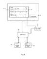
- Fig. 2 shows a schematic illustration of CPUs and video RAM in connection to a screen.
- the input window 11 is displayed on the screen 10, which can be a single channel display.
- the input window 11 is displayed by means of the graphical user interface of the MAIN CPU 23 so that data text, value, unit and/or operational status of the MAIN CPU (hardware of software component 20) are displayed.
- This MAIN CPU 23 is in connection to a FIRST SLAVE CPU 24 and SECOND SLAVE CPU 25.
- the FIRST SLAVE CPU 24 is associated to the control unit 30, whereas the SECOND SLAVE CPU 25 is associated to the supervisor unit 40.
- data text, value, unit of at least one adjusted parameter setting and/or operational status of the MAIN CPU 23 is represented in a screen image and captured (read back) by a video RAM 14 by a TASK in the MAIN CPU 23.
- the captured screen image is then decoded to data text, value, unit and/or operational status by a TASK in the MAIN CPU 23.
- Captured and decoded data is communicated from MAIN CPU 23 to SECOND SLAVE CPU 25 (hardware of supervisor unit 40) and then compared to the data in the SECOND SLAVE CPU 25 by a TASK in the SECOND SLAVE CPU 25 (data/task in hardware of supervisor unit 40). If any change is detected in the SECOND SLAVE CPU 25, a signal is triggered.
- data in both SLAVE CPUs 24 and 25 are cyclically received and sent and then compared to be equal except limited duration transients.
Landscapes
- Health & Medical Sciences (AREA)
- Engineering & Computer Science (AREA)
- Biomedical Technology (AREA)
- Public Health (AREA)
- Heart & Thoracic Surgery (AREA)
- Urology & Nephrology (AREA)
- General Health & Medical Sciences (AREA)
- Epidemiology (AREA)
- Anesthesiology (AREA)
- Medical Informatics (AREA)
- General Business, Economics & Management (AREA)
- Emergency Medicine (AREA)
- Business, Economics & Management (AREA)
- Vascular Medicine (AREA)
- Primary Health Care (AREA)
- Hematology (AREA)
- Life Sciences & Earth Sciences (AREA)
- Animal Behavior & Ethology (AREA)
- Veterinary Medicine (AREA)
- Measuring And Recording Apparatus For Diagnosis (AREA)
- Medical Treatment And Welfare Office Work (AREA)
Description
- The invention relates to a method for setting at least one safety relevant parameter of a microprocessor controlled medical apparatus, whereby processes of the medical apparatus are operated based at least on said parameter setting, and the medical apparatus comprises means for manual selection and amendment of the parameter setting by an operator.
- The invention further relates to a medical apparatus using this method.
- Modern medical apparatuses are often controlled by a microprocessor that, for example, operates pumps, reads sensors and communicates with an operator via a user interface like a monitor, keypad and/or touchscreen. This user interface can make use of text, pictograms and/or graphical icons to guide an operator through the setup and give him/her necessary information during a therapy that is performed by the medical apparatus.
- Thereby, parameter input is an essential part of such medical equipment. For example, extracorporal blood treatment (ECB) involves the continuous withdrawal of blood from a patient, where the blood is processed within a medical device outside of the patient and is then returned to the patient. Parameters like the ultrafiltration volume, the therapy time and the ultrafiltration rate can be input by a nurse depending on the patient's prescription, and the medical apparatus can then individually perform the therapy for each patient. The traditional way is the separate input of parameters, i.e. one by one entering the values by any means, and confirming these parameters before they are implemented. However, some of these parameters are mutually dependent from each other and possibly from the time passed during the therapy, which can cause usability problems. Therefore, U.S. Patent Application
US 2005/0256444 A1 , for example, suggests a user interface for a blood treatment device which allows to select and review a series of parameter settings and to implement the settings in batch manner. - In addition, the functional safety of medical equipment has been very much developed and essentially improved in the past two decades. In particular, if a patient is constantly connected to a medical apparatus like an extracorporal blood treatment device, any failure in entering or implementing a proper prescription can have negative impacts on the therapy and the patient's health. Therefore, it has to be guaranteed that the processes of a medical apparatus are actually controlled by the parameters that have been input by an operator.
- International Patent Application
WO 2006/131775 A1 , for example, describes a medical apparatus comprising a user interface for setting parameters that includes a screen for visualizing values of said parameters, a main control unit connected to the interface, a first memory and a video memory both connected to the main control unit for storing data corresponding to images on the screen. The main control unit allows setting of a new value for a parameter, displays the new value on the screen region, stores the new value in the first memory and captures from the video memory data that is representative of said screen region. Hereby, it can be verified from said representative data whether the displayed value corresponds to the value in the first memory, which is used for the processes of the medical apparatus during therapy. - Furthermore, the processes of a medical apparatus like an extracorporal blood treatment device are often controlled by a control software unit and additionally monitored by a supervisor software unit. Both software units have to be provided with the same parameters and statuses via two channels, and it can be considered an essential part of the functional safety of the medical apparatus to guarantee that the supervisor software's parameter and/or status is equal to the one(s) confirmed by the user and to those one(s) being used by the functional control unit. For this purpose, the parameters of the two channels can be displayed to the nurse on a screen, for example, who then has to compare the values for each software unit and can take measures, if they differ from each other. However, this requires awareness, time and concentration, whereby human decisions always involve certain risks.
- It is therefore an objective of the invention to provide an improved method for safety relevant input of parameters with little handling need and good handling consistency. It is another objective of the invention to provide a corresponding medical apparatus.
- According to the invention, this objective is achieved by a method having the features of independent Claim 1. Advantageous refinements of this method are set forth in dependent Claims 2 through 12. The objective is also achieved by a medical apparatus according to
Claim 13. - The method according to the invention can be used for setting at least one safety relevant parameter of a microprocessor controlled medical apparatus, whereby processes of the medical apparatus are operated based at least on said parameter setting. Thereby, the medical apparatus comprises a software component driving a user interface connected to a screen and means for manual selection and amendment of the parameter settings by an operator. The method comprises at least the following steps:
- displaying by means of the user interface the at least one safety relevant parameter in an input window on the screen;
- adjusting said parameter in the input window upon manual selection by an operator, and representing the new parameter in a screen image by means of a video RAM;
- communicating data regarding the new parameter from the user interface to a control unit and to a supervisor unit of the medical apparatus after a parameter setting acceptance operation is actuated by the operator;
- capturing the screen image from the video RAM and decoding the screen image to data regarding the new parameter;
- communicating the decoded data regarding the new parameter to the supervisor unit;
- comparing the data regarding the new parameter communicated from the user interface with the data regarding the new parameter communicated from the video RAM, wherein the result of the comparison leads to:
- generating a signal, if the data regarding the new parameter communicated from the user interface differs from the data regarding the new parameter communicated from the video RAM, or if data regarding the new parameter communicated from the video RAM did not arrive within a time-out at the supervisor unit after the parameter setting acceptance operation; or
- controlling processes of the medical apparatus by means of the control unit at least based on the data regarding the new parameter received by the control unit and communicating data regarding the running processes to the supervisor unit, if the data regarding the new parameter communicated from the user interface does not differ from the data regarding the new parameter communicated from the video RAM, and checking the processes by means of the supervisor unit.
- This method guarantees that the processes of the medical apparatus are performed based on those parameter settings that have been set and confirmed by an operator. If the communication of data regarding a new parameter setting from the user interface to the control unit and supervisor unit is somehow faulty, the video RAM will capture the parameter setting that has really been set by the operator and will communicate this data via a different channel. Both data regarding a new parameter setting can then be compared to generate a signal, if an inconsistency is detected. This signal can be used to issue an alarm, for example, which can be a visual and/or acoustic alarm that informs the operator of a problem with parameter settings. Thus, an operator like a nurse does not have to compare parameters on a screen, for example, because this is done automatically. The method according to the invention requires very little handling need and, consequently, less concentration and time of the user. However, the user is still to compare the settings of the machine to the prescription of the responsible physician.
- A user also does not have to know whether a parameter setting is safety relevant or not. This improves the handling consistency, because safety relevant parameters do not have to be confirmed by pressing an additional hardware button, for example, whereas non-safety relevant parameters might not have to be confirmed this way. With the invention, the user will only have to set the parameters and the medical apparatus will take care of the parameters depending on their safety relevance. Thereby, safety relevant parameters are displayed in a safety relevant input window and represented in the video RAM and non-safety relevant parameters will not, for example.
- The usability of the medical apparatus is improved by these measures, and the product costs for the equipment are lower than for other known solutions without reducing the level of functional safety that has already been achieved by these known solutions. The manufacturer needs equipment, which is cheaper to produce and cheaper to develop and maintain. Thus, the complexity of an equipment hardware-software system is also a cost issue, since less complexity means less
engineering effort in development and maintenance. Preferably, the screen according to the invention is a single channel display, and similar software can be used for the display and the screen capture feature, which keeps the complexity low. - The solution according to International Patent Application
WO 2006/131775 A1 , for example, is very complex, since it needs periodical comparisons in three relations of four memory sets, whereas the invention needs comparisons in only one relation of two memory sets. Furthermore, the solution according to said international application provides for safety relevant parameters only and not for status, but in a preferred embodiment of the invention, a parameter comprises data text, value, unit and/or the operational status of the medical apparatus. Therefore, a parameter within the meaning of this invention is not only a value of an ultrafiltration volume, for example, but might also be a status. - The operational status of the medical apparatus can be a therapy mode in which the medical apparatus performs a therapy on a patient, or a preparation mode in which the therapy is prepared, for example. Other statuses can also be considered, and at least the supervisor unit operates depending on the current status of the medical apparatus. Thus, the safety of monitoring the processes can be improved depending on the current status of the medical apparatus, and the solution according to said international application
WO 2006/131775 A1 has weaker functional safety than the invention. Furthermore, more than one parameter can be set and handled in batch manner by the method according to the invention. This further increases the usability of the device. - According to one (separate) aspect of the invention, data regarding the parameter communicated from the user interface to the control unit may be cyclically compared to the data regarding the parameter communicated from the user interface to the supervisor unit, and a signal is generated, if these data differ from each other.
- Preferably, a signal can inhibit the control of the processes based on new parameter settings so that the processes do not start or are based on current parameter settings.
- This ensures that processes are not controlled based on inconsistent parameter settings as long as they are not confirmed.
- The parameter setting acceptance operation can be actuated by pressing a soft button on the screen or by pressing a hardware button. Furthermore, another confirmation window can be provided to confirm an acceptance operation.
- The invention further comprises a medical apparatus, comprising at least a software component driving a user interface connected to a screen and means for manual selection and amendment of parameter settings by an operator, whereby processes of the medical apparatus are operated based on at least these parameter settings, and the medical apparatus comprises means configured to perform the method described above for setting safety relevant parameters. In one embodiment of the invention, the medical apparatus is an extracorporal blood treatment device that performs hemodialysis, hemofiltration, hemodialfiltration, ultrafiltration and/or plasmapheresis, for example, but the invention is not limited to this application. Since safety relevant parameter setting can be important for all kinds of medical apparatuses, the invention can have advantages for other applications, too.
- Additional advantages, special features and practical refinements of the invention can be gleaned from the dependent claims and from the presentation below of preferred embodiments making reference to the figures.
- The figures show the following:
- Fig. 1
- an example of a system architecture for implementing the method according to the invention; and
- Fig. 2
- a schematic illustration of CPUs and video RAM in connection to a screen.
-
Fig. 1 shows a diagram depicting the basic features of a system architecture of a microprocessor controlled extracorporal blood treatment device (ECB device), which is one example of a medical apparatus for which the invention can be used. The ECB device comprises at least an extracorporal blood circuit, pumps and sensors (not shown) and asoftware component 20 that controls processes 50 for performing the therapy functions of the ECB device. The processes can be performed on parameters like the ultrafiltration volume, the ultrafiltration rate and/or the therapy time, for example, which are set for each patient individually depending on the patient's description. - The ECB device also comprises a
screen 10 on which aparameter input window 11 can be displayed by the graphical user interface 21 (GUI) of thesoftware component 20 that runs on the MAIN CPU of the microprocessor controlled ECB device. Preferably, thescreen 10 is a touchscreen which allows displaying and inputting information to/by a user of the ECB device. - According to the embodiment of
Fig. 1 , thesoftware component 20 provides current parameter settings including statuses to twosoftware units parameter input window 11. Thefirst software unit 30 is a control unit (LLC) that controls theprocesses 50 of the device based on these parameter settings and statuses. Thereby, thecontrol software 30 drives pumps, feed-back controls, dialysate composition, sets valve positions, etc. The same parameter settings and statuses are provided to the supervisor unit (LLS) 40 that also receives data from theprocesses 50 and monitors these processes based on said received data and the parameter settings/statuses. It checks the pump speed, dialysate composition, valve positions, etc. using the same values as thecontrol unit 30, which were confirmed by the user. This can be called a two channel architecture and is illustrated on the left side of the system architecture inFig. 1 with continuous arrows. - The
software component 20 drives theuser interface 21 that is connected to thescreen 10 and comprises means for displaying theparameter input window 11 on thescreen 10. Data text, value and unit and/or operational status of the MAIN CPU are displayed on thesingle channel display 10. When parameters have been input in thisinput window 11 by an operator, they can be confirmed by touching a software "CONFIRM"button 12, for example. Alternatively or in addition, ahardware button 13 can be provided which can be pressed to confirm an amended setting. Parameter and status can be entered without confirmation, or changed data can be confirmed automatically. Upon confirmation, thesoftware component 20 stores the parameter settings and status in the local memory of theinput window 11 or thedata memory 22 of the MAIN CPU, respectively. Thecorresponding input window 11 can be closed, and theprocesses 50 of the ECB device are controlled by thecontrol unit 30 based on these amended/new parameter settings. As mentioned before, the amended/new parameter settings are also communicated to thesupervisor unit 40. Based on these settings and data received from theprocesses 50, thesupervisor unit 40 can check whether theprocesses 50 run correctly. - Furthermore, there is a data connection between the
control unit 30 and thesupervisor software 40 in order to exchange parameters and status. Thereby, data in their slave CPUs are cyclically received/sent and then compared to be equal except for limited duration transients. If the parameters and statuses used by thecontrol unit 30 and thesupervisor software 40 are not equal over transient time, an alarm is issued. If this difference is detected by thecontrol unit 30, a control alarm is issued, whereas as supervisor alarm is issued, if thesupervisor unit 40 detects the difference. - At the same time, a
video RAM 14 is operated between thescreen 10 and theGUI 21 of the MAIN CPU, which comprises aspecial video RAM 15 forparameter input window 11. Theparameter input window 11 serves for setting safety relevant parameters. Therefore, thisinput window 11 can also be called a safety relevant window, and safety relevant parameters can be captured by means of thevideo RAM 15 in order to provide them to thesupervisor unit 40 via a parallel channel. This additional channel from thevideo RAM 15 to thesupervisor unit 40 only is illustrated with dashed arrows on the right side of the system architecture inFig. 1 . - Thereby, data text, value and unit and/or operational status of the MAIN CPU is represented in a screen image by means of the
video RAM 15, and this screen image is captured/read back by a TASK in the MAIN CPU when the soft "CONFIRM"button 12 is pressed on thescreen 10, for example. The screen image is then decoded to data text, value and unit and/or operational status by another TASK in the MAIN CPU. Any method can be used for this decoding, e.g. comparing it to a desired image, or any pattern recognition method. The decoded data is then sent to thesupervisor unit 40 as described before. Thus, thesupervisor unit 40 receives parameter and status data via theuser interface 21 of the MAIN CPU and from thevideo RAM 15. - The data received from the
user interface 21 is sent to a SECOND SLAVE CPU, where any change is detected to start-time of receiving decoded screen. The decoded screen is communicated from the MAIN CPU to SECOND SLAVE CPU and then compared to the data in the SECOND SLAVE CPU by a TASK in the SECOND SLAVE CPU. If parameter and status received by thesupervisor unit 40 via the two channels differ from each other or a time-out is expired, a supervisor alarm is issued. Thus, an error in software can occur, if wrong contents were detected on the screen, or if the detection did not happen within a time limit. - Thereby, in safety relevant input the input of parameters and statuses are equally important. The status expresses whether the medical apparatus and the corresponding software are in preparation mode or therapy mode, for example. Having just safety relevant input for parameters, but not for statuses would be an unsafe design of the software system. Any software unit, therefore the
supervisor unit 40, too, contains features, which are operated depending on the status / statuses of the software. The status transition is normally triggered by pressing a button and then confirming a confirmation window ("Are you sure..."), i.e. by pressing another button once more. By this trigger the software system is supposed to change its status, i.e. all the components are supposed to change their statuses in the same way. If the design cannot guarantee that thesupervisor unit 40 is in the status, which used to be confirmed by the user, then the design remains unsafe regardless of parameters being input in a safe way. Thereby, if a user changes the status of the medical apparatus via theuser interface 21, it has to be guaranteed that this change of status is safely accounted for. - For example, if the safety relevant input of the set ultrafiltration volume (UF volume) is part of the design of the software system, one can be sure that the supervisor software memory will contain the correct set UF volume value that has been confirmed by the user. Nevertheless, the
supervisor unit 40 takes care of the UF volume (measures, calculates and compares it to the set value) in "Therapy" main phase/status only. It does not take care of the UF volume e.g. in "Preparation" main phase/status. Consequently, if the design cannot guarantee that thesupervisor unit 40 is in the "Therapy" status, which used to be confirmed by the user and not in the "Preparation" status any more, then the safely input set UF volume will be neglected, i.e. the UF volume will not be taken care of. - Furthermore, parameters and/or status do not have to be adjusted one by one, but they can be set in batch manner, too. For example, several settings can manually be performed by the user in the
input window 11, and they are handled in the same way in parallel upon confirmation by the operator. - The invention is further described by means of
Fig. 2 , which shows a schematic illustration of CPUs and video RAM in connection to a screen. Theinput window 11 is displayed on thescreen 10, which can be a single channel display. Thereby, theinput window 11 is displayed by means of the graphical user interface of theMAIN CPU 23 so that data text, value, unit and/or operational status of the MAIN CPU (hardware of software component 20) are displayed. ThisMAIN CPU 23 is in connection to aFIRST SLAVE CPU 24 andSECOND SLAVE CPU 25. TheFIRST SLAVE CPU 24 is associated to thecontrol unit 30, whereas theSECOND SLAVE CPU 25 is associated to thesupervisor unit 40. - Upon confirmation by the
soft button 12, for example, data text, value, unit of at least one adjusted parameter setting and/or operational status of theMAIN CPU 23 is represented in a screen image and captured (read back) by avideo RAM 14 by a TASK in theMAIN CPU 23. The captured screen image is then decoded to data text, value, unit and/or operational status by a TASK in theMAIN CPU 23. Captured and decoded data is communicated fromMAIN CPU 23 to SECOND SLAVE CPU 25 (hardware of supervisor unit 40) and then compared to the data in theSECOND SLAVE CPU 25 by a TASK in the SECOND SLAVE CPU 25 (data/task in hardware of supervisor unit 40). If any change is detected in theSECOND SLAVE CPU 25, a signal is triggered. Furthermore, data in bothSLAVE CPUs -
- 10
- Screen, touchscreen, display
- 11
- Parameter input window, safety relevant input window
- 12
- Soft "CONFIRM" button
- 13
- Hardware enter button
- 14
- Video RAM
- 15
- Video RAM for safety relevant window
- 20
- Software component
- 21
- Graphical user interface, GUI
- 22
- Storage unit, data memory of MAIN CPU
- 23
- MAIN CPU
- 24,25
- SLAVE CPU
- 30
- Control unit, LLC
- 40
- Supervisor unit, LLS
- 50
- Processes
Claims (14)
- Method for setting at least one safety relevant parameter of a microprocessor controlled medical apparatus, whereby processes (50) of the medical apparatus are operated based at least on said parameter setting and the medical apparatus comprises a software component (20) driving a user interface (21) connected to a screen (10), and the medical apparatus further comprises means for manual selection and amendment of the parameter setting by an operator, the method comprising:- displaying by means of the user interface (21) the at least one safety relevant parameter in an input window (11) on the screen (10);- adjusting said parameter in the input window (11) upon manual selection by an operator, and representing the new parameter in a screen image by means of a video RAM (14);- communicating data regarding the new parameter from the user interface (21) to a control unit (30) and to a supervisor unit (40) of the medical apparatus after a parameter setting acceptance operation is actuated by the operator;- capturing the screen image from the video RAM (14) and decoding the screen image to data regarding the new parameter;- communicating the decoded data regarding the new parameter to the supervisor unit (40);- comparing the data regarding the new parameter communicated from the user interface (21) with the data regarding the new parameter communicated from the video RAM (14), wherein the result of the comparison leads to:- generating a signal, if the data regarding the new parameter communicated from the user interface (21) differs from the data regarding the new parameter communicated from the video RAM (14), or if data regarding the new parameter communicated from the video RAM (14) did not arrive within a time-out at the supervisor unit (40) after the parameter setting acceptance operation; or- controlling processes (50) of the medical apparatus by means of the control unit (30) at least based on the data regarding the new parameter received by the control unit (30) and communicating data regarding the running processes (50) to the supervisor unit (40), if the data regarding the new parameter communicated from the user interface (21) does not differ from the data regarding the new parameter communicated from the video RAM (14), and checking the processes (50) by means of the supervisor unit (40).
- Method according to Claim 1, wherein the screen (10) is a single channel display.
- Method according to one or both of Claims 1 and 2, wherein the parameter comprises data text, value, unit and/or the operational status of the medical apparatus.
- Method according to one or more of Claims 1 to 3, wherein the operational status of the medical apparatus can at least be a therapy mode in which the medical apparatus performs a therapy on a patient, or a preparation mode in which the therapy is prepared.
- Method according to Claim 4, wherein at least the supervisor unit (40) operates depending on the operational status of the medical apparatus.
- Method according to one or more of Claims 1 to 5, wherein more than one parameter is set and handled in batch manner.
- Method according to one or more of Claims 1 to 6, wherein non-safety relevant parameters are not represented in the video RAM (14).
- Method according to one or more of Claims 1 to 7, wherein the data regarding the parameter communicated from the user interface (21) to the control unit (30) is cyclically compared to the data regarding the parameter communicated from the user interface (21) to the supervisor unit (40), and a signal is generated, if these data differ from each other.
- Method according to one or more of Claims 1 to 8, wherein the signal issues an alarm.
- Method according to Claim 9, wherein the alarm is a visual and/or acoustic alarm.
- Method according to one or more of Claims 1 to 10, wherein the signal inhibits the control of the processes (50) based on new parameter settings so that the processes (50) do not start or are based on current parameter settings.
- Method according to one or more of Claims 1 to 11, wherein the parameter setting acceptance operation is actuated by pressing a soft button (12) on the screen (10) or by pressing a hardware button (13).
- Medical apparatus, comprising at least a software component (20) driving a user interface (21) connected to a screen (10) and means for manual selection and amendment of parameter settings by an operator, whereby processes (50) of the medical apparatus are operated based on at least these parameter settings, characterized in that the medical apparatus comprises means configured to perform the method according to one or more of Claims 1 to 12 for setting safety relevant parameters.
- Medical apparatus according to Claim 13, wherein the medical apparatus is an extracorporal blood treatment device.
Priority Applications (1)
| Application Number | Priority Date | Filing Date | Title |
|---|---|---|---|
| EP12166674.7A EP2659919B1 (en) | 2012-05-03 | 2012-05-03 | Method for safety relevant parameter setting in a medical apparatus and medical apparatus |
Applications Claiming Priority (1)
| Application Number | Priority Date | Filing Date | Title |
|---|---|---|---|
| EP12166674.7A EP2659919B1 (en) | 2012-05-03 | 2012-05-03 | Method for safety relevant parameter setting in a medical apparatus and medical apparatus |
Publications (3)
| Publication Number | Publication Date |
|---|---|
| EP2659919A1 EP2659919A1 (en) | 2013-11-06 |
| EP2659919A8 EP2659919A8 (en) | 2014-02-12 |
| EP2659919B1 true EP2659919B1 (en) | 2014-12-10 |
Family
ID=46027813
Family Applications (1)
| Application Number | Title | Priority Date | Filing Date |
|---|---|---|---|
| EP12166674.7A Active EP2659919B1 (en) | 2012-05-03 | 2012-05-03 | Method for safety relevant parameter setting in a medical apparatus and medical apparatus |
Country Status (1)
| Country | Link |
|---|---|
| EP (1) | EP2659919B1 (en) |
Families Citing this family (2)
| Publication number | Priority date | Publication date | Assignee | Title |
|---|---|---|---|---|
| CN105013032B (en) | 2014-03-31 | 2018-06-22 | 甘布罗伦迪亚股份公司 | Extracorporeal blood treatment system and the method for the system |
| CN111831201A (en) * | 2020-05-25 | 2020-10-27 | 中国人民解放军陆军军医大学第二附属医院 | Human-computer interaction system and method for automatically detecting bone marrow cell morphology |
Family Cites Families (5)
| Publication number | Priority date | Publication date | Assignee | Title |
|---|---|---|---|---|
| SE457388B (en) * | 1985-06-04 | 1988-12-19 | Gambro Ab | MONITOR FOR CONTROL AND / OR CONTROL OF TWO OR MULTIPLE FUNCTIONS AND APPLICATION OF SUCH CIRCULAR CONTROL |
| US5620608A (en) * | 1995-06-07 | 1997-04-15 | Cobe Laboratories, Inc. | Information entry validation system and method for a dialysis machine |
| IT1320264B1 (en) * | 2000-09-29 | 2003-11-26 | Gambro Dasco Spa | DIALYSIS EQUIPMENT AND METHOD OF VERIFICATION OF THE FUNCTIONALITY OF A DIALYSIS EQUIPMENT. |
| US7303540B2 (en) | 2004-04-26 | 2007-12-04 | Chf Solutions, Inc. | User interface for blood treatment device |
| ES2344512T3 (en) | 2005-06-09 | 2010-08-30 | Gambro Lundia Ab | MEDICAL DEVICE AND METHOD TO CONFIGURE A MEDICAL DEVICE. |
-
2012
- 2012-05-03 EP EP12166674.7A patent/EP2659919B1/en active Active
Also Published As
| Publication number | Publication date |
|---|---|
| EP2659919A1 (en) | 2013-11-06 |
| EP2659919A8 (en) | 2014-02-12 |
Similar Documents
| Publication | Publication Date | Title |
|---|---|---|
| EP3248121B1 (en) | Remote monitoring interface device and mobile application for medical devices | |
| EP3304366B1 (en) | Alert on a dialysis machine | |
| EP2973094B1 (en) | Wearable interface for remote monitoring and control of a medical device | |
| JP4653218B2 (en) | Medical device and method for setting up a medical device | |
| CA2862361C (en) | Systems and methods for displaying objects at a medical treatment apparatus display screen | |
| US11058512B2 (en) | Sensor-controlled display output for dialysis machines | |
| US9703926B2 (en) | Method for customization of user interface of a medical apparatus for extracorporal blood treatment; medical apparatus for extracorporal blood treatment | |
| CN111009310B (en) | Medical system, medical equipment and control method thereof | |
| EP3072074B1 (en) | Dialysis apparatus with versatile user interface and method and computer program therefor | |
| EP2659919B1 (en) | Method for safety relevant parameter setting in a medical apparatus and medical apparatus | |
| JP6207019B2 (en) | Blood purification system | |
| JP5729868B2 (en) | Blood purification equipment | |
| US11642446B2 (en) | Blood purification system | |
| US20240299637A1 (en) | Contactless proximity controls for a medical device | |
| US12027081B2 (en) | Medical device with a display and with a processing unit and method therefor | |
| US20210125712A1 (en) | Maintenance notification for medical devices | |
| US20180039750A1 (en) | Processing repeated error messages in a dialysis machine | |
| WO2024141389A2 (en) | Medical device remote screen view methods, apparatus, and system |
Legal Events
| Date | Code | Title | Description |
|---|---|---|---|
| PUAI | Public reference made under article 153(3) epc to a published international application that has entered the european phase |
Free format text: ORIGINAL CODE: 0009012 |
|
| AK | Designated contracting states |
Kind code of ref document: A1 Designated state(s): AL AT BE BG CH CY CZ DE DK EE ES FI FR GB GR HR HU IE IS IT LI LT LU LV MC MK MT NL NO PL PT RO RS SE SI SK SM TR |
|
| AX | Request for extension of the european patent |
Extension state: BA ME |
|
| RIN1 | Information on inventor provided before grant (corrected) |
Inventor name: KINORANYI, GABOR Inventor name: SCHIN, ROBERT D. Inventor name: DOLGOS, SANDOR DR. Inventor name: BOGATIN, GYOERGY Inventor name: SZAMKO, PETER |
|
| RIN1 | Information on inventor provided before grant (corrected) |
Inventor name: DOLGOS, SANDOR, DR. Inventor name: SCHIN, ROBERT D. Inventor name: SZAMKO, PETER Inventor name: KINORANYI, GABOR Inventor name: BOGATIN, GYOERGY |
|
| 17P | Request for examination filed |
Effective date: 20140120 |
|
| RBV | Designated contracting states (corrected) |
Designated state(s): AL AT BE BG CH CY CZ DE DK EE ES FI FR GB GR HR HU IE IS IT LI LT LU LV MC MK MT NL NO PL PT RO RS SE SI SK SM TR |
|
| GRAP | Despatch of communication of intention to grant a patent |
Free format text: ORIGINAL CODE: EPIDOSNIGR1 |
|
| RIC1 | Information provided on ipc code assigned before grant |
Ipc: A61M 1/16 20060101AFI20140526BHEP |
|
| INTG | Intention to grant announced |
Effective date: 20140624 |
|
| GRAS | Grant fee paid |
Free format text: ORIGINAL CODE: EPIDOSNIGR3 |
|
| GRAA | (expected) grant |
Free format text: ORIGINAL CODE: 0009210 |
|
| AK | Designated contracting states |
Kind code of ref document: B1 Designated state(s): AL AT BE BG CH CY CZ DE DK EE ES FI FR GB GR HR HU IE IS IT LI LT LU LV MC MK MT NL NO PL PT RO RS SE SI SK SM TR |
|
| REG | Reference to a national code |
Ref country code: GB Ref legal event code: FG4D |
|
| REG | Reference to a national code |
Ref country code: CH Ref legal event code: EP |
|
| REG | Reference to a national code |
Ref country code: SE Ref legal event code: TRGR |
|
| REG | Reference to a national code |
Ref country code: IE Ref legal event code: FG4D |
|
| REG | Reference to a national code |
Ref country code: AT Ref legal event code: REF Ref document number: 700333 Country of ref document: AT Kind code of ref document: T Effective date: 20150115 |
|
| REG | Reference to a national code |
Ref country code: DE Ref legal event code: R096 Ref document number: 602012004188 Country of ref document: DE Effective date: 20150122 |
|
| REG | Reference to a national code |
Ref country code: AT Ref legal event code: MK05 Ref document number: 700333 Country of ref document: AT Kind code of ref document: T Effective date: 20141210 Ref country code: NL Ref legal event code: VDEP Effective date: 20141210 |
|
| REG | Reference to a national code |
Ref country code: NL Ref legal event code: VDEP Effective date: 20141210 |
|
| PG25 | Lapsed in a contracting state [announced via postgrant information from national office to epo] |
Ref country code: FI Free format text: LAPSE BECAUSE OF FAILURE TO SUBMIT A TRANSLATION OF THE DESCRIPTION OR TO PAY THE FEE WITHIN THE PRESCRIBED TIME-LIMIT Effective date: 20141210 Ref country code: NO Free format text: LAPSE BECAUSE OF FAILURE TO SUBMIT A TRANSLATION OF THE DESCRIPTION OR TO PAY THE FEE WITHIN THE PRESCRIBED TIME-LIMIT Effective date: 20150310 Ref country code: ES Free format text: LAPSE BECAUSE OF FAILURE TO SUBMIT A TRANSLATION OF THE DESCRIPTION OR TO PAY THE FEE WITHIN THE PRESCRIBED TIME-LIMIT Effective date: 20141210 Ref country code: LT Free format text: LAPSE BECAUSE OF FAILURE TO SUBMIT A TRANSLATION OF THE DESCRIPTION OR TO PAY THE FEE WITHIN THE PRESCRIBED TIME-LIMIT Effective date: 20141210 |
|
| REG | Reference to a national code |
Ref country code: FR Ref legal event code: PLFP Year of fee payment: 4 |
|
| REG | Reference to a national code |
Ref country code: LT Ref legal event code: MG4D |
|
| PG25 | Lapsed in a contracting state [announced via postgrant information from national office to epo] |
Ref country code: GR Free format text: LAPSE BECAUSE OF FAILURE TO SUBMIT A TRANSLATION OF THE DESCRIPTION OR TO PAY THE FEE WITHIN THE PRESCRIBED TIME-LIMIT Effective date: 20150311 Ref country code: AT Free format text: LAPSE BECAUSE OF FAILURE TO SUBMIT A TRANSLATION OF THE DESCRIPTION OR TO PAY THE FEE WITHIN THE PRESCRIBED TIME-LIMIT Effective date: 20141210 Ref country code: LV Free format text: LAPSE BECAUSE OF FAILURE TO SUBMIT A TRANSLATION OF THE DESCRIPTION OR TO PAY THE FEE WITHIN THE PRESCRIBED TIME-LIMIT Effective date: 20141210 Ref country code: RS Free format text: LAPSE BECAUSE OF FAILURE TO SUBMIT A TRANSLATION OF THE DESCRIPTION OR TO PAY THE FEE WITHIN THE PRESCRIBED TIME-LIMIT Effective date: 20141210 Ref country code: HR Free format text: LAPSE BECAUSE OF FAILURE TO SUBMIT A TRANSLATION OF THE DESCRIPTION OR TO PAY THE FEE WITHIN THE PRESCRIBED TIME-LIMIT Effective date: 20141210 |
|
| PG25 | Lapsed in a contracting state [announced via postgrant information from national office to epo] |
Ref country code: NL Free format text: LAPSE BECAUSE OF FAILURE TO SUBMIT A TRANSLATION OF THE DESCRIPTION OR TO PAY THE FEE WITHIN THE PRESCRIBED TIME-LIMIT Effective date: 20141210 |
|
| PG25 | Lapsed in a contracting state [announced via postgrant information from national office to epo] |
Ref country code: RO Free format text: LAPSE BECAUSE OF FAILURE TO SUBMIT A TRANSLATION OF THE DESCRIPTION OR TO PAY THE FEE WITHIN THE PRESCRIBED TIME-LIMIT Effective date: 20141210 Ref country code: EE Free format text: LAPSE BECAUSE OF FAILURE TO SUBMIT A TRANSLATION OF THE DESCRIPTION OR TO PAY THE FEE WITHIN THE PRESCRIBED TIME-LIMIT Effective date: 20141210 Ref country code: PT Free format text: LAPSE BECAUSE OF FAILURE TO SUBMIT A TRANSLATION OF THE DESCRIPTION OR TO PAY THE FEE WITHIN THE PRESCRIBED TIME-LIMIT Effective date: 20150410 Ref country code: SK Free format text: LAPSE BECAUSE OF FAILURE TO SUBMIT A TRANSLATION OF THE DESCRIPTION OR TO PAY THE FEE WITHIN THE PRESCRIBED TIME-LIMIT Effective date: 20141210 Ref country code: CZ Free format text: LAPSE BECAUSE OF FAILURE TO SUBMIT A TRANSLATION OF THE DESCRIPTION OR TO PAY THE FEE WITHIN THE PRESCRIBED TIME-LIMIT Effective date: 20141210 |
|
| PG25 | Lapsed in a contracting state [announced via postgrant information from national office to epo] |
Ref country code: PL Free format text: LAPSE BECAUSE OF FAILURE TO SUBMIT A TRANSLATION OF THE DESCRIPTION OR TO PAY THE FEE WITHIN THE PRESCRIBED TIME-LIMIT Effective date: 20141210 Ref country code: IS Free format text: LAPSE BECAUSE OF FAILURE TO SUBMIT A TRANSLATION OF THE DESCRIPTION OR TO PAY THE FEE WITHIN THE PRESCRIBED TIME-LIMIT Effective date: 20150410 |
|
| REG | Reference to a national code |
Ref country code: DE Ref legal event code: R097 Ref document number: 602012004188 Country of ref document: DE |
|
| PLBE | No opposition filed within time limit |
Free format text: ORIGINAL CODE: 0009261 |
|
| STAA | Information on the status of an ep patent application or granted ep patent |
Free format text: STATUS: NO OPPOSITION FILED WITHIN TIME LIMIT |
|
| PG25 | Lapsed in a contracting state [announced via postgrant information from national office to epo] |
Ref country code: DK Free format text: LAPSE BECAUSE OF FAILURE TO SUBMIT A TRANSLATION OF THE DESCRIPTION OR TO PAY THE FEE WITHIN THE PRESCRIBED TIME-LIMIT Effective date: 20141210 |
|
| 26N | No opposition filed |
Effective date: 20150911 |
|
| REG | Reference to a national code |
Ref country code: CH Ref legal event code: PL |
|
| PG25 | Lapsed in a contracting state [announced via postgrant information from national office to epo] |
Ref country code: MC Free format text: LAPSE BECAUSE OF FAILURE TO SUBMIT A TRANSLATION OF THE DESCRIPTION OR TO PAY THE FEE WITHIN THE PRESCRIBED TIME-LIMIT Effective date: 20141210 Ref country code: LU Free format text: LAPSE BECAUSE OF FAILURE TO SUBMIT A TRANSLATION OF THE DESCRIPTION OR TO PAY THE FEE WITHIN THE PRESCRIBED TIME-LIMIT Effective date: 20150503 Ref country code: LI Free format text: LAPSE BECAUSE OF NON-PAYMENT OF DUE FEES Effective date: 20150531 Ref country code: CH Free format text: LAPSE BECAUSE OF NON-PAYMENT OF DUE FEES Effective date: 20150531 |
|
| REG | Reference to a national code |
Ref country code: IE Ref legal event code: MM4A |
|
| PG25 | Lapsed in a contracting state [announced via postgrant information from national office to epo] |
Ref country code: SI Free format text: LAPSE BECAUSE OF FAILURE TO SUBMIT A TRANSLATION OF THE DESCRIPTION OR TO PAY THE FEE WITHIN THE PRESCRIBED TIME-LIMIT Effective date: 20141210 |
|
| PG25 | Lapsed in a contracting state [announced via postgrant information from national office to epo] |
Ref country code: IE Free format text: LAPSE BECAUSE OF NON-PAYMENT OF DUE FEES Effective date: 20150503 |
|
| REG | Reference to a national code |
Ref country code: FR Ref legal event code: PLFP Year of fee payment: 5 |
|
| PG25 | Lapsed in a contracting state [announced via postgrant information from national office to epo] |
Ref country code: BE Free format text: LAPSE BECAUSE OF FAILURE TO SUBMIT A TRANSLATION OF THE DESCRIPTION OR TO PAY THE FEE WITHIN THE PRESCRIBED TIME-LIMIT Effective date: 20141210 |
|
| PG25 | Lapsed in a contracting state [announced via postgrant information from national office to epo] |
Ref country code: MT Free format text: LAPSE BECAUSE OF FAILURE TO SUBMIT A TRANSLATION OF THE DESCRIPTION OR TO PAY THE FEE WITHIN THE PRESCRIBED TIME-LIMIT Effective date: 20141210 |
|
| GBPC | Gb: european patent ceased through non-payment of renewal fee |
Effective date: 20160503 |
|
| REG | Reference to a national code |
Ref country code: FR Ref legal event code: PLFP Year of fee payment: 6 |
|
| PG25 | Lapsed in a contracting state [announced via postgrant information from national office to epo] |
Ref country code: BG Free format text: LAPSE BECAUSE OF FAILURE TO SUBMIT A TRANSLATION OF THE DESCRIPTION OR TO PAY THE FEE WITHIN THE PRESCRIBED TIME-LIMIT Effective date: 20141210 Ref country code: GB Free format text: LAPSE BECAUSE OF NON-PAYMENT OF DUE FEES Effective date: 20160503 Ref country code: HU Free format text: LAPSE BECAUSE OF FAILURE TO SUBMIT A TRANSLATION OF THE DESCRIPTION OR TO PAY THE FEE WITHIN THE PRESCRIBED TIME-LIMIT; INVALID AB INITIO Effective date: 20120503 Ref country code: SM Free format text: LAPSE BECAUSE OF FAILURE TO SUBMIT A TRANSLATION OF THE DESCRIPTION OR TO PAY THE FEE WITHIN THE PRESCRIBED TIME-LIMIT Effective date: 20141210 |
|
| PG25 | Lapsed in a contracting state [announced via postgrant information from national office to epo] |
Ref country code: CY Free format text: LAPSE BECAUSE OF FAILURE TO SUBMIT A TRANSLATION OF THE DESCRIPTION OR TO PAY THE FEE WITHIN THE PRESCRIBED TIME-LIMIT Effective date: 20141210 |
|
| PG25 | Lapsed in a contracting state [announced via postgrant information from national office to epo] |
Ref country code: TR Free format text: LAPSE BECAUSE OF FAILURE TO SUBMIT A TRANSLATION OF THE DESCRIPTION OR TO PAY THE FEE WITHIN THE PRESCRIBED TIME-LIMIT Effective date: 20141210 |
|
| REG | Reference to a national code |
Ref country code: FR Ref legal event code: PLFP Year of fee payment: 7 |
|
| PG25 | Lapsed in a contracting state [announced via postgrant information from national office to epo] |
Ref country code: MK Free format text: LAPSE BECAUSE OF FAILURE TO SUBMIT A TRANSLATION OF THE DESCRIPTION OR TO PAY THE FEE WITHIN THE PRESCRIBED TIME-LIMIT Effective date: 20141210 |
|
| PG25 | Lapsed in a contracting state [announced via postgrant information from national office to epo] |
Ref country code: AL Free format text: LAPSE BECAUSE OF FAILURE TO SUBMIT A TRANSLATION OF THE DESCRIPTION OR TO PAY THE FEE WITHIN THE PRESCRIBED TIME-LIMIT Effective date: 20141210 |
|
| PGFP | Annual fee paid to national office [announced via postgrant information from national office to epo] |
Ref country code: DE Payment date: 20240517 Year of fee payment: 13 |
|
| PGFP | Annual fee paid to national office [announced via postgrant information from national office to epo] |
Ref country code: FR Payment date: 20240523 Year of fee payment: 13 |
|
| PGFP | Annual fee paid to national office [announced via postgrant information from national office to epo] |
Ref country code: SE Payment date: 20240522 Year of fee payment: 13 |
|
| PGFP | Annual fee paid to national office [announced via postgrant information from national office to epo] |
Ref country code: IT Payment date: 20240531 Year of fee payment: 13 |