EP2659761A1 - Harvesting machine with a cutting device - Google Patents
Harvesting machine with a cutting device Download PDFInfo
- Publication number
- EP2659761A1 EP2659761A1 EP13155019.6A EP13155019A EP2659761A1 EP 2659761 A1 EP2659761 A1 EP 2659761A1 EP 13155019 A EP13155019 A EP 13155019A EP 2659761 A1 EP2659761 A1 EP 2659761A1
- Authority
- EP
- European Patent Office
- Prior art keywords
- knife carrier
- support frame
- harvesting machine
- crop
- machine according
- Prior art date
- Legal status (The legal status is an assumption and is not a legal conclusion. Google has not performed a legal analysis and makes no representation as to the accuracy of the status listed.)
- Granted
Links
Images


Classifications
-
- A—HUMAN NECESSITIES
- A01—AGRICULTURE; FORESTRY; ANIMAL HUSBANDRY; HUNTING; TRAPPING; FISHING
- A01D—HARVESTING; MOWING
- A01D90/00—Vehicles for carrying harvested crops with means for selfloading or unloading
- A01D90/02—Loading means
- A01D90/04—Loading means with additional cutting means
-
- A—HUMAN NECESSITIES
- A01—AGRICULTURE; FORESTRY; ANIMAL HUSBANDRY; HUNTING; TRAPPING; FISHING
- A01F—PROCESSING OF HARVESTED PRODUCE; HAY OR STRAW PRESSES; DEVICES FOR STORING AGRICULTURAL OR HORTICULTURAL PRODUCE
- A01F15/00—Baling presses for straw, hay or the like
- A01F15/08—Details
- A01F15/10—Feeding devices for the crop material e.g. precompression devices
- A01F2015/107—Means for withdrawing knives, rotor or walls of the feeding chamber in case of plugging or congestion
-
- A—HUMAN NECESSITIES
- A01—AGRICULTURE; FORESTRY; ANIMAL HUSBANDRY; HUNTING; TRAPPING; FISHING
- A01F—PROCESSING OF HARVESTED PRODUCE; HAY OR STRAW PRESSES; DEVICES FOR STORING AGRICULTURAL OR HORTICULTURAL PRODUCE
- A01F15/00—Baling presses for straw, hay or the like
- A01F15/08—Details
- A01F15/10—Feeding devices for the crop material e.g. precompression devices
- A01F2015/108—Cutting devices comprising cutter and counter-cutter
Definitions
- the invention relates to a harvester, in particular a baler or a loader wagon with a cutting device for agricultural crop according to the preamble of claim 1.
- Agricultural balers or self-loading wagons are often equipped with a cutting device - also called “cutting unit” - supplied for the machine stalk and / or sheet material (in the following simplified: “crop") equipped to crush this for different purposes.
- a cutting device also called “cutting unit” - supplied for the machine stalk and / or sheet material (in the following simplified: “crop") equipped to crush this for different purposes.
- Other agricultural harvesters may also be equipped with such a cutting device.
- the cutting device is in each case arranged in a flow-through by the crop channel of the baler, the loading wagon or other agricultural machine so that the crop is supported on a projecting into the channel number fixed knife to be cut in contact with the knife edges.
- the conveyance of the crop in the area of action of the knives is effected, in particular, by a rotor which rotates about an axis transverse to the flow direction and is equipped in the axial direction with a multiplicity of rotor stars.
- the rotor stars are usually slightly twisted to each other mounted on the axis to achieve a largely continuous promotion of the crop and even load on the associated drive train.
- such cutting devices have a multiplicity of knives arranged side by side in rows, wherein the number of knives protruding next to one another into the crop channel dictates the number of effective cut edges and thus an achievable cut length of the crop. It is generally desirable to be able to use different numbers of blades to adapt to the particular application or the harvesting conditions. To protect the knives against damage by stones or other particles that are generally not comminuted and to allow selection of a desired number of knives, it is customary to store the blades so movable relative to a blade carrier of the cutting device, that each blade can be adjusted between at least one operating position and an inoperative position.
- the knife In the operating position, the knife is in a position in which it protrudes into the Erntegutkanal that past flowing crop is crushed in cooperation with the knife. In the inoperative position, however, the knife is in a position in which it is largely withdrawn from the crop channel, so the crop does not cut.
- a complex adjusting mechanism which includes, among other things, the individual knives associated clamping units and a common actuating device.
- Such cutting devices require a great deal of effort when it comes to wear-related blade replacement. The required for the blade change access to the close below the Erntegutkanals arranged knives is difficult in practice.
- a harvester with the features of claim 1.
- the knife carrier is mounted linearly movable in a direction extending transversely to Erntegutkanal direction, so that the knife carrier from a relative to the Erntegutkanal central position on both sides in each of which lateral positions is movable, in which the knife carrier respectively at least half out of the canal.
- the double-sided movable storage ensures that the knife carrier, for example, for the purpose of maintenance and / or repair of individual knives (or associated adjusting mechanism) by moving to the right or left of the harvester can be completely moved out of the inaccessible installation area below the Erntegutkanals.
- the knife carrier By shifting to the right more than half of the right part of the knife carrier protrudes from the channel, by a shift to the left protrudes more than half of the left part of the knife carrier out of the channel.
- the knife carrier In the central position, the knife carrier is in a central position relative to the crop channel, which position is also assumed during operation in order to achieve the full effectiveness of the cutting device.
- the arrangement according to the invention has the advantage that the blade carrier can be made in one piece, with only a small lateral space requirement for blade replacement due to the two-sided, each partially extensibility and no extended holding forces in the extended state of a - whatever design - holding structure are applied ,
- the knife carrier is held by a support frame which is mounted about an axis extending transversely to the Erntegutkanal pivotally relative to the machine frame of the harvester.
- the knife carrier is thus not only laterally displaceable, but by means of the pivotable support frame with respect to the Erntegutkanal pivoted.
- the pivotability is advantageously used to be able to spend the knife carrier from a crop channel final operating position in a maintenance position in which the crop channel is at least partially open and thus accessible for maintenance or repair purposes.
- the operating position of the maintenance position preferably differs in that in the operating position, the knife carrier is prevented laterally from the walls of the Erntegutkanals in the movement, while in the maintenance position, the knife carrier from its central position is movable into lateral positions.
- the support frame by means of a suitable actuator from a closed state in which the knife carrier is enclosed laterally from the crop channel, in an open state (maintenance position) pivotable in which the knife carrier is movable into lateral positions.
- a suitable actuator from a closed state in which the knife carrier is enclosed laterally from the crop channel, in an open state (maintenance position) pivotable in which the knife carrier is movable into lateral positions.
- this could be serve in pairs between the machine frame and the support frame acting hydraulic actuating cylinder.
- Other actuators are conceivable. With the help of actuators in any case ensures that the adjustment of the blade carrier between the operating position and the maintenance position for a machine operator without effort, for example, remotely from an operator terminal, perform.
- An advantageous development of the invention provides that the knife carrier relative to the support frame by means of linear guide means is mounted like a drawer.
- the knife carrier is in this case designed similar to a drawer, i. as a structural unit, which is held displaceable by the support frame.
- On the support frame guide means are expediently provided, which cooperate with complementary guide means of the knife carrier to allow the two-sided lateral pushing out of the knife carrier.
- a transversely to the crop channel extending front rail and a transversely extending to Erntegutkanal rear rail are arranged on the knife carrier each, which are held by arranged on the support frame bearing elements on a transverse to the crop channel guide path.
- the bearing elements are several rollers arranged over the width of the support frame, the front rail and the rear rail also resting on at least two of these rollers in the lateral positions of the knife carrier. In the manner mentioned, therefore, a roller bearing of the knife carrier is created, resulting in a particularly smooth and low-friction mounting of the knife carrier. Since the knife carrier in each case rests on at least two rollers, secure storage is ensured in all positions of the knife carrier.
- the knife carrier projects at least half out of the crop channel in the lateral positions.
- the storage is such that the knife carrier protrudes in the lateral positions to about 60% (of its own width) from the crop channel, since it has been shown that with such a design even at relatively easy construction of the supporting frame can achieve sufficient accessibility.
- the cutting device is associated with the crop channel down over the blade carrier covering Gutleitelement in which a plurality of slit-like recesses for the blades arranged on the knife carrier is formed. It is in the Gutleitelement in particular a floor plate that limits the Erntegutkanal down to the knife carrier, inter alia, to protect the knife carrier from contamination by crop.
- the bottom plate is mounted pivotably relative to the machine frame of the harvester about an axis extending transversely to the crop channel.
- the pivotability of the bottom plate allows that in a closed position of the bottom plate of the crop channel is closed down.
- the crop channel is at least partially opened downwards, so that the crop channel, in particular a cutting rotor located therein, is accessible for maintenance and repair purposes.
- a particularly advantageous embodiment provides that the bottom plate and the support frame are mounted pivotably about the same axis relative to the machine frame of the harvester. By such a storage, it is possible to pivot the support frame with it held knife carrier about the same axis as the bottom plate. It can be provided that the base plate and the support frame of the knife carrier are connected to each other, so that, depending on requirements, a common pivoting as a unit or a separate pivoting is possible.
- Fig. 1 shows a baler 1 in the form of a square baler at harvest time in a schematic side view.
- the baler takes 1 lying on the field soil crop 2, for example, laid to swath straw and processed this to cuboid pressed and tied with twine bale 3, which are ejected after completion of the baler 1.
- the baler 1 picks up the crop 2 from the ground by means of a rotating picking drum 5 occupied by tines in order to feed it, in cooperation with two overlying hold-down rollers 4, to the further conveying and processing devices of the baling press 1.
- the crop 2 is brought together by a conveying member 6, such as a cross auger, from an original receiving width of the collecting drum 5 to a smaller width of the feed channel 9 and (not shown) by means of on the conveying member 6 centrally arranged conveyor paddle to a downstream (cutting) Rotor 7 promoted.
- the rotor 7 has over the width thereof a plurality of mutually spaced rotor stars.
- the rotor stars are arranged, for example, helically on the rotor 7 in order to achieve a uniform conveying action and a uniform load of the associated drive train.
- the cutting device 16 essentially has a multiplicity of knives 8, which, with respect to the feed channel 9, extend transversely to the conveying direction of the crop 2 are arranged side by side. Accordingly, only one in the drawing view front (seen in the direction of travel of the press 1 left) knife 8 of the cutting device 16 can be seen, which - as the other knives 8 - is pivotable about a transverse to Gutellecardi knife axis 17. Each knife 8 is thus pivotable between an inoperative position, in which it does not protrude into the crop channel, and an operating position, in which it projects into the crop channel.
- the crop 2 flowing through the feed channel 9 is comminuted, in particular cut, by intermeshing cooperation of the rotor 7 (its rotor stars) and the respective knife 8.
- the crop 2 After passing through the cutting device 16, the crop 2 is collected by a gatherer performing Raffer 10, which then in portions an overlying pressing chamber 11 fills. After the pressing process takes place there, a knotting device 12 is used to tie the pressed bale 3 with twine to complete this. The rear side of the baler 1 is then the bale dump.
- Front of the baler 1 is a drawbar 15 with which the baler 1 is pulled by a towing vehicle such as a tractor (not shown) and driven by this.
- a towing vehicle such as a tractor (not shown)
- To drive the conveying and processing facilities of the baler 1 is a coupled to the tractor main drive shaft 14, which opens into a main gearbox 13.
- FIG. 2 to 5 now show in detail a cutting device 16, the in a baler 1 according to Fig. 1 can be installed in different states in perspective view.
- This shows first Fig. 2 a cutting device 16 with closed support frame 21, ie in its closed state (Z closed ).
- the cutting device 16 is supported by a machine frame 18, which in the exemplary embodiment shown comprises support elements with a rectangular profile arranged on both sides of the rotor 7 and welded together at an obtuse angle.
- a rotor 7 having a plurality of rotor stars (not individually designated) attached thereto is rotatably supported relative to the machine frame 18.
- a curved bottom plate 20 which limits a crop channel 9 (indicated by the incoming and outgoing arrows 9) over its entire width downwards.
- the base plate 20 is pivotally mounted relative to the machine frame 18 about a transversely to the Erntegutkanal 9 extending pivot axis 22.
- a plurality of slot-like recesses are formed over its width (in Fig. 2 occluded closed due to the closed state Z), by which a number of knives 8 (in Fig. 2 also hidden) can protrude into the crop channel 9.
- a support frame 21 is mounted pivotably relative to the machine frame 18 about the pivot axis 22 extending transversely to the crop channel 9.
- the support frame 21 holds a knife carrier 27 located thereunder, to which a plurality of knives 8 (in FIG Fig. 2 covered) in relation to the crop channel 9 are arranged in series next to each other. Due to the pivotability of the support frame 21 about the pivot axis 22 and the knife carrier 27 carried thereby is pivotable about the pivot axis 22.
- the pair of adjusting cylinders 19 acts between the machine frame 18 and the support frame 21 in the sense of an actuator to the support frame 21 of a in Fig. 2 shown closed state Z closed , in which the knife carrier 27 is laterally enclosed by side walls of the crop channel 9, in an in Fig. 3 shown opened state Z can pivot open , in which the knife carrier 27 is movable in lateral positions.
- FIG. 3 shows Fig. 3 the cutting device 16 with the support frame 21 open (open state Z open ) in a perspective view.
- the actuating cylinder 19 are different from Fig. 2 extended, so that the support frame 21 together with attached knife carrier 27 relative to the Erntegutkanal 9 (in comparison to Fig. 2 ) is lowered.
- the floor panel 20 is in the same position as in FIG Fig. 2 , namely is locked by means of a locking lever 24 relative to the machine frame 18.
- opened state Z open the support frame 21st Accordingly, a region located between the lowered knife carrier 27 and the bottom plate 20 is released.
- the knife carrier 27 is centered in each case in a central position P relative to the Erntegutkanal 9, that is, the knife carrier 27 is arranged centrally between the adjusting cylinders 19. According to the invention, however, the knife carrier 27 is mounted linearly movable in a direction transverse to the Erntegutkanal 9 extending direction, so that this from the in the Fig. 2 and 3 shown central position P centrally on both sides in each case can move lateral positions in which the knife carrier 27 projects at least half out of the Erntegutkanal 9.
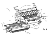
- FIG. 4 shows Fig. 4 the cutting device 16, wherein the blade carrier 27 opened from the open state of the Z Fig. 3 has been moved to a left position P left
- Fig. 5 the cutting device 16, wherein the blade carrier 27 opened from the open state of the Z Fig. 3 moved to a right position P on the right .
- the knife carrier 27 is designed in the sense of a drawer, which is mounted laterally displaceable relative to the holding support frame 21.
- a plurality of support rollers 23 arranged over the width of the crop channel 9 are arranged for this purpose.
- four support rollers 23 are arranged at a rear cross member of the support frame 21 at regular intervals.
- the rear rail 25 and the front rail 26 are held by the support rollers 23 of the support frame 21 so on a transversely to Erntegutkanal 9 extending track that the entire knife carrier 27 - in the open state of the support frame 21 - from the central position P center according to Fig. 3 in the left position P left according to Fig. 4 , or in the right position P right according to Fig. 5 lets move.
- the knife carrier 27 projects laterally out of the crop channel 9 to about 60% of its width.
- the support rollers 23 are each below the front or rear rail 26 and 25, it is also ensured that falling by the cutting process particles that fall, for example, formed by the bottom plate 20 slot-like recesses, not with the linear guide means, in particular the Support rollers 23 and the cooperating rails 25, 26 come into contact and contaminate them.
- baler P in the middle central position crop P left left position 3 bale P right right position 4 Hold-down rollers 5
- Aufnroterommel Z closed closed state 6 conveying member Z open opened state 7
- rotor 8th knife 9 feed 10
- raffer 11 baling chamber 12
- knotting device 13 main gearbox 14
- Main drive shaft 15 drawbar 16 cutter 17 blade axis 18 machine frame 19 actuating cylinder 20 floor panel 21 supporting frame 22 swivel axis 23 supporting role 24
Abstract
Description
Die Erfindung betrifft eine Erntemaschine, insbesondere eine Ballenpresse oder einen Ladewagen mit einer Schneidvorrichtung für landwirtschaftliches Erntegut gemäß dem Oberbegriff des Anspruchs 1.The invention relates to a harvester, in particular a baler or a loader wagon with a cutting device for agricultural crop according to the preamble of claim 1.
Landwirtschaftliche Ballenpressen oder Ladewagen sind oftmals mit einer Schneidvorrichtung - auch "Schneidwerk" genannt - für der Maschine zugeführtes Halm- und/oder Blattgut (im Folgenden vereinfacht: "Erntegut") ausgestattet, um dieses zu unterschiedlichen Zwecken zu zerkleinern. Auch andere landwirtschaftliche Erntemaschinen können mit einer solchen Schneidvorrichtung ausgestattet sein.Agricultural balers or self-loading wagons are often equipped with a cutting device - also called "cutting unit" - supplied for the machine stalk and / or sheet material (in the following simplified: "crop") equipped to crush this for different purposes. Other agricultural harvesters may also be equipped with such a cutting device.
Die Schneidvorrichtung ist dabei jeweils in einem vom Erntegut durchströmten Kanal der Ballenpresse, des Ladewagens oder sonstigen landwirtschaftlichen Maschine so angeordnet, dass das Erntegut auf eine in den Kanal hineinragende Anzahl feststehender Messer zu gefördert wird, um in Kontakt mit den Messerkanten geschnitten zu werden. Im Fall von Ballenpressen und Ladewagen wird die Förderung des Ernteguts im Wirkungsbereich der Messer insbesondere durch einen Rotor bewirkt, der sich um eine quer zur Gutstromrichtung liegende Achse dreht und in Axialrichtung mit einer Vielzahl von Rotorsternen ausgestattet ist. Die Rotorsterne sind in der Regel leicht verdreht zueinander auf der Achse montiert, um eine weitestgehend kontinuierliche Förderung des Ernteguts sowie gleichmäßige Belastung des zugehörigen Antriebsstrangs zu erzielen.The cutting device is in each case arranged in a flow-through by the crop channel of the baler, the loading wagon or other agricultural machine so that the crop is supported on a projecting into the channel number fixed knife to be cut in contact with the knife edges. In the case of balers and loader wagons, the conveyance of the crop in the area of action of the knives is effected, in particular, by a rotor which rotates about an axis transverse to the flow direction and is equipped in the axial direction with a multiplicity of rotor stars. The rotor stars are usually slightly twisted to each other mounted on the axis to achieve a largely continuous promotion of the crop and even load on the associated drive train.
In Bezug auf den durchströmten Erntegutkanal weisen derartige Schneidvorrichtungen eine Vielzahl in Reihe nebeneinander angeordneter Messer auf, wobei die Anzahl nebeneinander in den Erntegutkanal ragender Messer die Anzahl wirksamer Schnittkanten und damit eine erzielbare Schnittlänge des Ernteguts vorgibt. Es ist allgemein wünschenswert, unterschiedliche Messeranzahlen verwenden zu können, um sich dem jeweiligen Einsatzzweck bzw. den Erntebedingungen anzupassen. Zum Schutz der Messer vor Beschädigungen durch Steine oder sonstige allgemein nicht zerkleinerbare Partikel und zur Ermöglichung einer Auswahl einer gewünschten Messeranzahl ist es üblich, die Messer derart beweglich gegenüber einem Messerträger der Schneidvorrichtung zu lagern, dass sich jedes Messer zwischen zumindest einer Betriebsposition und einer Außerbetriebsposition verstellen lässt. In der Betriebsposition befindet sich das Messer dabei in einer Stellung, in der es so in den Erntegutkanal hineinragt, dass vorbeiströmendes Erntegut in Zusammenwirkung mit dem Messer zerkleinert wird. In der Außerbetriebsposition befindet sich das Messer dagegen in einer Stellung, in der es aus dem Erntegutkanal weitestgehend zurückgezogen ist, das Erntegut also nicht schneidet. Zum individuellen Spannen und Halten der Messer in den verschiedenen Betriebs- bzw. Außerbetriebspositionen dient eine aufwendige Stellmechanik, die unter anderem den einzelnen Messern zugeordnete Spanneinheiten sowie eine gemeinsame Stelleinrichtung umfasst. Schon angesichts der großen Anzahl heute verbauter Messer in Schneidvorrichtungen fällt bei derartigen Schneidvorrichtungen ein hoher Aufwand beim verschleißbedingten Messerwechsel an. Der für den Messerwechsel erforderliche Zugang zu den dicht unterhalb des Erntegutkanals angeordneten Messern ist in der Praxis schwierig.With regard to the flow-through crop channel, such cutting devices have a multiplicity of knives arranged side by side in rows, wherein the number of knives protruding next to one another into the crop channel dictates the number of effective cut edges and thus an achievable cut length of the crop. It is generally desirable to be able to use different numbers of blades to adapt to the particular application or the harvesting conditions. To protect the knives against damage by stones or other particles that are generally not comminuted and to allow selection of a desired number of knives, it is customary to store the blades so movable relative to a blade carrier of the cutting device, that each blade can be adjusted between at least one operating position and an inoperative position. In the operating position, the knife is in a position in which it protrudes into the Erntegutkanal that past flowing crop is crushed in cooperation with the knife. In the inoperative position, however, the knife is in a position in which it is largely withdrawn from the crop channel, so the crop does not cut. For individual clamping and holding of the knives in the various operating or inoperative positions is a complex adjusting mechanism, which includes, among other things, the individual knives associated clamping units and a common actuating device. In view of the large number of knives installed today in cutting devices, such cutting devices require a great deal of effort when it comes to wear-related blade replacement. The required for the blade change access to the close below the Erntegutkanals arranged knives is difficult in practice.
Aus dem Stand der Technik ist es beispielsweise bekannt sich zu Wartungs- und/oder Reparaturzwecken Zugänglichkeit zu den Messern zu verschaffen, indem der mit den Messern bestückte Messerträger einseitig aus der Erntemaschine herausziehbar gestaltet ist, um die Messer dann von der einen Maschinenseite tauschen zu können. Nachteilig daran ist, dass aufgrund des Gewichts und der erforderlichen Auszuglänge des Messerträgers ein aufwendiger Aufbau des diesen tragenden Rahmens erforderlich ist. Zudem erfordert der voll ausgezogene Messerträger viel seitlichen Platz.From the state of the art, it is known, for example, to obtain accessibility to the knives for maintenance and / or repair purposes, in that the knife carrier equipped with the knives is designed to be extractable from the harvester on one side so that the knives can then be exchanged by one side of the machine , The disadvantage of this is that due to the weight and the required extension length of the blade carrier a complex structure of this supporting frame is required. In addition, the fully extended knife carrier requires a lot of lateral space.
Es ist daher eine Aufgabe der vorliegenden Erfindung, eine mit einer Schneidvorrichtung ausgestattete Erntemaschine anzugeben, die bei geringem Platzbedarf und verhältnismäßig leichter Konstruktion einfachen Zugang zu den Messern gewährleistet, um diese auf bequeme Weise warten bzw. austauschen zu können.It is therefore an object of the present invention to provide a harvesting machine equipped with a cutting device, which ensures easy access to the knives in a small footprint and relatively light construction in order to maintain or exchange them in a comfortable way.
Die genannte Aufgabe wird gelöst durch eine Erntemaschine mit den Merkmalen des Anspruchs 1. Diese zeichnet sich dadurch aus, dass der Messerträger in einer sich quer zum Erntegutkanal erstreckenden Richtung linear beweglich gelagert ist, so dass der Messerträger aus einer bezogen auf den Erntegutkanal mittigen Position beidseitig in jeweils davon seitliche Positionen bewegbar ist, in denen der Messerträger jeweils zumindest zur Hälfte aus dem Kanal hinausragt. Erfindungsgemäß ist durch die beidseitig bewegbare Lagerung gewährleistet, dass der Messerträger beispielsweise zum Zweck der Wartung und/oder Reparatur einzelner Messer (oder zugehöriger Stellmechanik) durch Verschiebung nach rechts oder links der Erntemaschine vollständig aus dem unzugänglichen Einbaubereich unterhalb des Erntegutkanals herausbewegt werden kann. Durch eine Verschiebung nach rechts ragt dabei mehr als die Hälfte des rechten Teils des Messerträgers aus dem Kanal hervor, durch eine Verschiebung nach links ragt mehr als die Hälfte des linken Teils des Messerträgers aus dem Kanal hervor. In der mittigen Position befindet sich der Messerträger in einer bezogen auf den Erntegutkanal zentralen Stellung, die auch im Betrieb einzunehmen ist, um die volle Wirksamkeit der Schneideinrichtung zu erzielen. Die erfindungsgemäße Anordnung bietet den Vorteil, dass der Messerträger einteilig gefertigt sein kann, wobei durch die beidseitige, jeweils teilweise Ausziehbarkeit nur ein geringer seitlicher Platzbedarf beim Messerwechsel besteht und im ausgezogenen Zustand von einer - wie auch immer gestalteten - Haltestruktur keine übermäßig hohen Haltekräfte aufzubringen sind.This object is achieved by a harvester with the features of claim 1. This is characterized in that the knife carrier is mounted linearly movable in a direction extending transversely to Erntegutkanal direction, so that the knife carrier from a relative to the Erntegutkanal central position on both sides in each of which lateral positions is movable, in which the knife carrier respectively at least half out of the canal. According to the double-sided movable storage ensures that the knife carrier, for example, for the purpose of maintenance and / or repair of individual knives (or associated adjusting mechanism) by moving to the right or left of the harvester can be completely moved out of the inaccessible installation area below the Erntegutkanals. By shifting to the right more than half of the right part of the knife carrier protrudes from the channel, by a shift to the left protrudes more than half of the left part of the knife carrier out of the channel. In the central position, the knife carrier is in a central position relative to the crop channel, which position is also assumed during operation in order to achieve the full effectiveness of the cutting device. The arrangement according to the invention has the advantage that the blade carrier can be made in one piece, with only a small lateral space requirement for blade replacement due to the two-sided, each partially extensibility and no extended holding forces in the extended state of a - whatever design - holding structure are applied ,
Gemäß einer vorteilhaften Weiterbildung der Erfindung wird der Messerträger von einem Tragrahmen gehalten, der um eine quer zum Erntegutkanal verlaufende Achse schwenkbar gegenüber dem Maschinenrahmen der Erntemaschine gelagert ist. Der Messerträger ist damit nicht nur seitlich verschiebbar, sondern mittels des schwenkbaren Tragrahmens in Bezug auf den Erntegutkanal verschwenkbar. Die Verschwenkbarkeit dient vorteilhaft dazu, den Messerträger aus einer den Erntegutkanal abschließenden Betriebsposition in eine Wartungsposition verbringen zu können, in welcher der Erntegutkanal zumindest teilweise geöffnet und damit zu Wartungs- bzw. Reparaturzwecken zugänglich ist. Weiterhin unterscheidet sich die Betriebsposition von der Wartungsposition vorzugsweise darin, dass in der Betriebsposition der Messerträger seitlich von den Wänden des Erntegutkanals in der Bewegung gehindert ist, während in der Wartungsposition der Messerträger aus seiner mittigen Position in seitliche Positionen bewegbar ist.According to an advantageous embodiment of the invention, the knife carrier is held by a support frame which is mounted about an axis extending transversely to the Erntegutkanal pivotally relative to the machine frame of the harvester. The knife carrier is thus not only laterally displaceable, but by means of the pivotable support frame with respect to the Erntegutkanal pivoted. The pivotability is advantageously used to be able to spend the knife carrier from a crop channel final operating position in a maintenance position in which the crop channel is at least partially open and thus accessible for maintenance or repair purposes. Furthermore, the operating position of the maintenance position preferably differs in that in the operating position, the knife carrier is prevented laterally from the walls of the Erntegutkanals in the movement, while in the maintenance position, the knife carrier from its central position is movable into lateral positions.
Vorteilhaft ist demnach der Tragrahmen mittels einer geeigneten Aktorik aus einem geschlossenen Zustand, in dem der Messerträger seitlich vom Erntegutkanal eingeschlossen ist, in einen geöffneten Zustand (Wartungsposition) verschwenkbar, in dem der Messerträger in seitliche Positionen bewegbar ist. Beispielsweise könnten hierzu paarweise zwischen dem Maschinenrahmen und dem Tragrahmen wirkende hydraulische Stellzylinder dienen. Auch andere Aktoren sind denkbar. Mit Hilfe der Aktorik ist jedenfalls gewährleistet, dass sich die Verstellung des Messerträgers zwischen der Betriebsposition und der Wartungsposition für einen Maschinenbediener ohne Kraftaufwand, beispielsweise ferngesteuert von einem Bedienterminal, durchführen lässt.Advantageously, therefore, the support frame by means of a suitable actuator from a closed state in which the knife carrier is enclosed laterally from the crop channel, in an open state (maintenance position) pivotable in which the knife carrier is movable into lateral positions. For example, this could be serve in pairs between the machine frame and the support frame acting hydraulic actuating cylinder. Other actuators are conceivable. With the help of actuators in any case ensures that the adjustment of the blade carrier between the operating position and the maintenance position for a machine operator without effort, for example, remotely from an operator terminal, perform.
Für die Lagerung des Messerträgers kommen verschiedene Möglichkeiten in Betracht. Eine vorteilhafte Weiterbildung der Erfindung sieht vor, dass der Messerträger gegenüber dem Tragrahmen mittels linearer Führungsmittel schubladenartig gelagert ist. Der Messerträger ist in diesem Fall ähnlich einer Schublade gestaltet, d.h. als eine bauliche Einheit, die vom Tragrahmen verschiebbar gehalten wird. Am Tragrahmen sind dazu zweckmäßigerweise Führungsmittel vorgesehen, die mit dazu komplementären Führungsmitteln des Messerträgers zusammenwirken, um das beidseitige seitliche Ausschieben des Messerträgers zu ermöglichen.For the storage of the knife carrier different possibilities are considered. An advantageous development of the invention provides that the knife carrier relative to the support frame by means of linear guide means is mounted like a drawer. The knife carrier is in this case designed similar to a drawer, i. as a structural unit, which is held displaceable by the support frame. On the support frame guide means are expediently provided, which cooperate with complementary guide means of the knife carrier to allow the two-sided lateral pushing out of the knife carrier.
Gemäß einer konstruktiv günstigen Ausgestaltung sind am Messerträger jeweils eine quer zum Erntegutkanal verlaufende vordere Schiene und eine quer zum Erntegutkanal verlaufende hintere Schiene angeordnet, die mittels am Tragrahmen angeordneter Lagerelemente auf einer quer zum Erntegutkanal verlaufenden Führungsbahn gehalten werden. Besonders vorteilhaft handelt es sich bei den Lagerelementen um mehrere über die Breite des Tragrahmens angeordnete Rollen, wobei die vordere Schiene und die hintere Schiene auch in den seitlichen Positionen des Messerträger auf zumindest zwei dieser Rollen aufliegen. Auf die genannte Weise ist demnach eine Rollenlagerung des Messerträgers geschaffen, wodurch sich eine besonders leichtgängige und reibungsarme Lagerung des Messerträgers ergibt. Da der Messerträger jeweils auf zumindest zwei Rollen aufliegt, ist in sämtlichen Positionen des Messerträgers eine sichere Lagerung gewährleistet.According to a structurally favorable embodiment, a transversely to the crop channel extending front rail and a transversely extending to Erntegutkanal rear rail are arranged on the knife carrier each, which are held by arranged on the support frame bearing elements on a transverse to the crop channel guide path. Particularly advantageously, the bearing elements are several rollers arranged over the width of the support frame, the front rail and the rear rail also resting on at least two of these rollers in the lateral positions of the knife carrier. In the manner mentioned, therefore, a roller bearing of the knife carrier is created, resulting in a particularly smooth and low-friction mounting of the knife carrier. Since the knife carrier in each case rests on at least two rollers, secure storage is ensured in all positions of the knife carrier.
Erfindungsgemäß ragt der Messerträger in den seitlichen Positionen jeweils zumindest zur Hälfte aus dem Erntegutkanal hinaus. Gemäß einer besonders platzsparenden und bedienfreundlichen Gestaltung ist die Lagerung so beschaffen, dass der Messerträger in den seitlichen Positionen zu etwa 60% (seiner eigenen Breite) aus dem Erntegutkanal hinausragt, da sich gezeigt hat, dass sich mit einer solchen Gestaltung auch bei verhältnismäßig leichtem Aufbau des tragenden Rahmens eine hinreichende Zugänglichkeit erzielen lässt.According to the invention, the knife carrier projects at least half out of the crop channel in the lateral positions. According to a particularly space-saving and user-friendly design, the storage is such that the knife carrier protrudes in the lateral positions to about 60% (of its own width) from the crop channel, since it has been shown that with such a design even at relatively easy construction of the supporting frame can achieve sufficient accessibility.
Zweckmäßigerweise ist der Schneidvorrichtung ein den Erntegutkanal nach unten gegenüber dem Messerträger abdeckendes Gutleitelement zugeordnet, in dem eine Vielzahl schlitzartiger Ausnehmungen für die am Messerträger angeordneten Messer ausgebildet ist. Es handelt sich bei dem Gutleitelement insbesondere um ein Bodenblech, das den Erntegutkanal nach unten gegenüber dem Messerträger begrenzt, um unter anderem den Messerträger vor Verschmutzungen durch Erntegut zu schützen.Conveniently, the cutting device is associated with the crop channel down over the blade carrier covering Gutleitelement in which a plurality of slit-like recesses for the blades arranged on the knife carrier is formed. It is in the Gutleitelement in particular a floor plate that limits the Erntegutkanal down to the knife carrier, inter alia, to protect the knife carrier from contamination by crop.
Gemäß einer bevorzugten Weiterbildung der Erntemaschine ist das Bodenblech um eine quer zum Erntegutkanal verlaufende Achse schwenkbar gegenüber dem Maschinenrahmen der Erntemaschine gelagert. Die Schwenkbarkeit des Bodenblechs ermöglicht, dass in einer geschlossenen Stellung des Bodenblechs der Erntegutkanal nach unten geschlossen ist. In einer geöffneten Stellung des Bodenblechs ist der Erntegutkanal dagegen nach unten zumindest teilweise geöffnet, so dass der Erntegutkanal, insbesondere ein darin befindlicher Schneidrotor zu Wartungs- und Reparaturzwecken zugänglich ist.According to a preferred embodiment of the harvester, the bottom plate is mounted pivotably relative to the machine frame of the harvester about an axis extending transversely to the crop channel. The pivotability of the bottom plate allows that in a closed position of the bottom plate of the crop channel is closed down. By contrast, in an open position of the floor panel, the crop channel is at least partially opened downwards, so that the crop channel, in particular a cutting rotor located therein, is accessible for maintenance and repair purposes.
Eine besonders vorteilhafte Ausgestaltung sieht vor, dass das Bodenblech und der Tragrahmen um die gleiche Achse schwenkbar gegenüber dem Maschinenrahmen der Erntemaschine gelagert sind. Durch eine solche Lagerung ist es möglich, den Tragrahmen mit daran gehaltenem Messerträger um die gleiche Achse wie das Bodenblech zu verschwenken. Es kann vorgesehen sein, dass das Bodenblech und der Tragrahmen des Messerträgers miteinander verbindbar sind, so dass je nach Bedarf ein gemeinsames Verschwenken als eine Einheit oder ein separates Verschwenken möglich ist.A particularly advantageous embodiment provides that the bottom plate and the support frame are mounted pivotably about the same axis relative to the machine frame of the harvester. By such a storage, it is possible to pivot the support frame with it held knife carrier about the same axis as the bottom plate. It can be provided that the base plate and the support frame of the knife carrier are connected to each other, so that, depending on requirements, a common pivoting as a unit or a separate pivoting is possible.
Die Erfindung wird im Folgenden unter Hinweis auf die beigefügten Figuren anhand eines bevorzugten Ausführungsbeispiels näher erläutert. Daraus ergeben sich auch weitere Einzelheiten und Vorteile der Erfindung. Es zeigen:
- Fig. 1
- eine Ballenpresse in schematischer Seitenansicht,
- Fig. 2
- eine Schneidvorrichtung einer Ballenpresse bei geschlossenem Tragrahmen in perspektivischer Ansicht,
- Fig. 3
- die Schneidvorrichtung der
Fig. 2 bei geöffnetem Tragrahmen in perspektivischer Ansicht, - Fig. 4
- die Schneidvorrichtung der
Fig. 3 , wobei der Messerträger in eine linke Position bewegt wurde, - Fig. 5
- die Schneidvorrichtung der
Fig. 3 , wobei der Messerträger in eine rechte Position bewegt wurde.
- Fig. 1
- a baler in a schematic side view,
- Fig. 2
- a cutting device of a baler with a closed support frame in perspective view,
- Fig. 3
- the cutting device of
Fig. 2 with open support frame in perspective view, - Fig. 4
- the cutting device of
Fig. 3 with the knife carrier moved to a left position, - Fig. 5
- the cutting device of
Fig. 3 with the knife carrier moved to a right position.
Dazu nimmt die Ballenpresse 1 das Erntegut 2 mittels einer mit Zinken besetzten rotierenden Aufsammeltrommel 5 vom Boden auf, um es in Zusammenwirkung mit zwei darüberliegenden Niederhalterollen 4 den weiteren Förder- und Verarbeitungseinrichtungen der Ballenpresse 1 zuzuführen. Als nächstes wird das Erntegut 2 von einem Förderorgan 6, beispielsweise einer Querförderschnecke, von einer ursprünglichen Aufnahmebreite der Aufsammeltrommel 5 auf eine geringere Breite des Zuführkanals 9 zusammengeführt und mittels auf dem Förderorgan 6 mittig angeordneter Förderpaddel (nicht dargestellt) zu einem nachgelagerten (Schneid-) Rotor 7 gefördert. Der Rotor 7 weist über dessen Breite eine Vielzahl von zueinander beabstandeten Rotorsternen auf. Die Rotorsterne sind beispielsweise wendelförmig auf dem Rotor 7 angeordnet, um eine gleichmäßige Förderwirkung sowie eine gleichmäßige Belastung des zugehörigen Antriebsstrangs zu erzielen.For this purpose, the baler 1 picks up the
Unterhalb des Rotors 7 ist eine schematisch dargestellte Schneidvorrichtung 16 angeordnet. Die Schneidvorrichtung 16 weist im Wesentlichen eine Vielzahl von Messern 8 auf, die in Bezug auf den Zuführkanal 9 quer zur Förderrichtung des Ernteguts 2 nebeneinander angeordnet sind. Demzufolge ist nur ein in der Zeichnungsansicht vorderes (in Fahrtrichtung der Presse 1 gesehen linkes) Messer 8 der Schneidvorrichtung 16 zu sehen, das - wie auch die übrigen Messer 8 - um eine quer zur Gutförderrichtung verlaufende Messerachse 17 verschwenkbar ist. Jedes Messer 8 ist so zwischen einer Außerbetriebsposition, in der es nicht in den Erntegutkanal hineinragt, und einer Betriebsposition verschwenkbar, in der es in den Erntegutkanal hineinragt. Befindet sich ein Messer 8 (bzw. eine Vielzahl oder sämtliche der Messer 8) in der Betriebsposition, so wird das den Zuführkanal 9 durchströmende Erntegut 2 durch kämmende Zusammenwirkung von Rotor 7 (dessen Rotorsternen) und dem jeweiligen Messer 8 zerkleinert, insbesondere geschnitten.Below the rotor 7 a schematically illustrated
Nach Passieren der Schneidvorrichtung 16 wird das Erntegut 2 von einem Sammelhübe durchführenden Raffer 10 gesammelt, der dann portionsweise eine darüberliegende Presskammer 11 befüllt. Nach dem dort stattfindenden Pressvorgang dient eine Knoteinrichtung 12 dazu, den gepressten Ballen 3 mit Bindegarn zu verschnüren, um diesen fertig zu stellen. Heckseitig der Ballenpresse 1 erfolgt anschließend der Ballenabwurf.After passing through the cutting
Frontseitig der Ballenpresse 1 befindet sich eine Zugdeichsel 15, mit der die Ballenpresse 1 von einem Zugfahrzeug wie einem Traktor (nicht dargestellt) gezogen und von diesem angetrieben wird. Zum Antrieb der Förder- und Verarbeitungseinrichtungen der Ballenpresse 1 dient eine mit dem Traktor koppelbare Hauptantriebswelle 14, die in ein Hauptgetriebe 13 mündet.Front of the baler 1 is a
Die
Unmittelbar unterhalb des Rotors 7 erstreckt sich ein gebogenes Bodenblech 20, das einen Erntegutkanal 9 (angedeutet durch die ein- und austretenden Pfeile 9) über dessen gesamte Breite nach unten begrenzt. Das Bodenblech 20 ist um eine quer zum Erntegutkanal 9 verlaufende Schwenkachse 22 schwenkbar gegenüber dem Maschinenrahmen 18 drehbar gelagert. In dem Bodenblech 20 sind über dessen Breite eine Vielzahl schlitzartiger Ausnehmungen ausgebildet (in
Zusätzlich zum Bodenblech 20 ist ein Tragrahmen 21 um die quer zum Erntegutkanal 9 verlaufende Schwenkachse 22 schwenkbar gegenüber dem Maschinenrahmen 18 gelagert. Der Tragrahmen 21 hält einen sich darunter befindlichen Messerträger 27, an dem eine Vielzahl von Messern 8 (in
Zur Betätigung des Tragrahmens 21 dienen zwei beidseitig des Erntegutkanals 9 angeordnete hydraulische Stellzylinder 19 (in der perspektivischen Ansicht der
Dementsprechend zeigt
In den
Dementsprechend zeigt
Wie
Durch Einnahme der beiden Positionen Plinks bzw. Prechts lassen sich demnach sämtliche Messer 8 bequem erreichen, um diese beispielsweise auszutauschen, zu reinigen oder um sich aus sonstigen Gründen Zugang zum Messerträger 27 zu verschaffen. Aufgrund der gleichmäßigen Anordnung der vier Tragrollen 23 wird die hintere Schiene 25 auch in den seitlichen Positionen Plinks bzw. Prechts des Messerträgers 27 von jeweils zumindest zwei der Tragrollen 23 kontaktiert. So ist auch in den voll ausgefahrenen Positionen Plinks bzw. Prechts ein sicherer Halt des Messerträgers 27 im Tragrahmen 21 gewährleistet. Da sich die Tragrollen 23 jeweils unterhalb der vorderen bzw. hinteren Schiene 26 bzw. 25 befinden, ist zudem gewährleistet, dass durch den Schneidvorgang anfallende Partikel, die beispielsweise durch die im Bodenblech 20 ausgebildeten schlitzartigen Ausnehmungen fallen, nicht mit den linearen Führungsmitteln, insbesondere den Tragrollen 23 sowie den damit zusammenwirkenden Schienen 25, 26 in Kontakt geraten und diese verunreinigen.By taking the two positions P left or P right , therefore, all the knives 8 can be easily reached, for example, to exchange them, to clean or to gain access to the
Claims (10)
dadurch gekennzeichnet, dass der Messerträger (27) in einer sich quer zum Erntegutkanal (9) erstreckenden Richtung linear beweglich gelagert ist, so dass der Messerträger (27) aus einer bezogen auf den Erntegutkanal (9) mittigen Position (Pmittig) beidseitig in jeweils davon seitliche Positionen (Plink,, Prechts) bewegbar ist, in denen der Messerträger (27) jeweils zumindest zur Hälfte aus dem Kanal (9) hinausragt.Harvesting machine, in particular baling press (1) or loading wagons, with a cutting device (16) for agricultural crop (2), wherein the cutting device (16) comprises a number of knives (8) which are in relation to a crop channel through which crop material (2) flows (9) are arranged in series next to each other on a knife carrier (27) and are each adjustable between at least one operating position and a non-operating position,
characterized in that the knife carrier (27) in a transversely to the Erntegutkanal (9) extending direction is mounted linearly movable, so that the knife carrier (27) from a relative to the Erntegutkanal (9) central position (P centered ) on both sides in each case thereof lateral positions (P link ,, P right ) is movable, in which the knife carrier (27) in each case at least half protrudes from the channel (9).
Applications Claiming Priority (1)
| Application Number | Priority Date | Filing Date | Title |
|---|---|---|---|
| DE201210008721 DE102012008721A1 (en) | 2012-05-03 | 2012-05-03 | Harvester with a cutting device |
Publications (2)
| Publication Number | Publication Date |
|---|---|
| EP2659761A1 true EP2659761A1 (en) | 2013-11-06 |
| EP2659761B1 EP2659761B1 (en) | 2017-05-10 |
Family
ID=47748417
Family Applications (1)
| Application Number | Title | Priority Date | Filing Date |
|---|---|---|---|
| EP13155019.6A Active EP2659761B1 (en) | 2012-05-03 | 2013-02-13 | Harvesting machine with a cutting device |
Country Status (2)
| Country | Link |
|---|---|
| EP (1) | EP2659761B1 (en) |
| DE (1) | DE102012008721A1 (en) |
Cited By (2)
| Publication number | Priority date | Publication date | Assignee | Title |
|---|---|---|---|---|
| CN104054471A (en) * | 2014-05-21 | 2014-09-24 | 南通棉花机械有限公司 | Grass feed device for joint operation machine of reaping and bundling of grains |
| EP4140289A1 (en) * | 2021-08-23 | 2023-03-01 | Usines Claas France S.A.S | Agricultural baler |
Families Citing this family (3)
| Publication number | Priority date | Publication date | Assignee | Title |
|---|---|---|---|---|
| DE202014003759U1 (en) * | 2014-04-30 | 2015-07-31 | Alois Pöttinger Maschinenfabrik Gmbh | Agricultural machine |
| US10462974B2 (en) | 2016-07-27 | 2019-11-05 | Deere & Company | Two stage knife floor |
| EP3959961A1 (en) * | 2020-08-26 | 2022-03-02 | Georg Rubenbauer | Baler press with removable cutting module and method for handling such a removable cutting module |
Citations (4)
| Publication number | Priority date | Publication date | Assignee | Title |
|---|---|---|---|---|
| DE3711355C1 (en) * | 1987-04-03 | 1988-04-28 | Mengele & Soehne Masch Karl | Loading wagons |
| DE3821717A1 (en) * | 1987-04-03 | 1990-01-11 | Mengele & Soehne Masch Karl | Loading truck |
| DE9308656U1 (en) * | 1993-06-09 | 1993-08-12 | Alois Poettinger Maschinenfabrik Ges.M.B.H., Grieskirchen, At | |
| US20080028737A1 (en) * | 2006-08-03 | 2008-02-07 | Jean Viaud | Conveyor Assembly For A Baler |
-
2012
- 2012-05-03 DE DE201210008721 patent/DE102012008721A1/en not_active Withdrawn
-
2013
- 2013-02-13 EP EP13155019.6A patent/EP2659761B1/en active Active
Patent Citations (4)
| Publication number | Priority date | Publication date | Assignee | Title |
|---|---|---|---|---|
| DE3711355C1 (en) * | 1987-04-03 | 1988-04-28 | Mengele & Soehne Masch Karl | Loading wagons |
| DE3821717A1 (en) * | 1987-04-03 | 1990-01-11 | Mengele & Soehne Masch Karl | Loading truck |
| DE9308656U1 (en) * | 1993-06-09 | 1993-08-12 | Alois Poettinger Maschinenfabrik Ges.M.B.H., Grieskirchen, At | |
| US20080028737A1 (en) * | 2006-08-03 | 2008-02-07 | Jean Viaud | Conveyor Assembly For A Baler |
Cited By (2)
| Publication number | Priority date | Publication date | Assignee | Title |
|---|---|---|---|---|
| CN104054471A (en) * | 2014-05-21 | 2014-09-24 | 南通棉花机械有限公司 | Grass feed device for joint operation machine of reaping and bundling of grains |
| EP4140289A1 (en) * | 2021-08-23 | 2023-03-01 | Usines Claas France S.A.S | Agricultural baler |
Also Published As
| Publication number | Publication date |
|---|---|
| DE102012008721A1 (en) | 2013-11-07 |
| EP2659761B1 (en) | 2017-05-10 |
Similar Documents
| Publication | Publication Date | Title |
|---|---|---|
| EP2067399B1 (en) | Arrangement to adjust the position of a pick-up drum and a pressing element in an agricultural harvesting machine | |
| EP2979535B1 (en) | Cutting device for agricultural harvesters | |
| EP1121012B1 (en) | Cutting device for an agricultural harvester | |
| EP2659761B1 (en) | Harvesting machine with a cutting device | |
| EP2653025B1 (en) | Cutting device for agricultural crops | |
| DE102011013242B4 (en) | baler | |
| EP2742794B1 (en) | Agricultural harvesting machine and method for servicing such a harvesting machine | |
| AT394126B (en) | CUTTING DEVICE FOR STRAW AND / OR LEAF | |
| EP2659763B1 (en) | Harvesting machine with a cutting device | |
| EP3092890B1 (en) | Cutting assembly for a harvester | |
| EP2939521B1 (en) | Agricultural machine | |
| EP2659762B1 (en) | Agricultural harvester with a cutting device | |
| EP3111742B1 (en) | Cutting device and harvesting machine | |
| EP3981245B1 (en) | Agricultural stalk press and method for depositing bales made of pressed stalk material | |
| DE102006053771B4 (en) | Machine for mowing stalk-like crops | |
| DE102008043577B4 (en) | Machine for mowing stalk-like crops | |
| DE2218773C3 (en) | Agricultural trailer with a loading device | |
| DE102022105847A1 (en) | Swath pickup with third support wheel | |
| EP3959961A1 (en) | Baler press with removable cutting module and method for handling such a removable cutting module | |
| DE102007002670B4 (en) | Machine for mowing stalk-like crops | |
| DE102022124860A1 (en) | Harvesting attachment for harvesting stem-like plants | |
| DE102022115512A1 (en) | Foldable pick-up attachment for a harvester | |
| DE102019109479A1 (en) | Harvester with a cutting device | |
| DE102015200536A1 (en) | Green waste cutting plant for use on a forage harvester | |
| DE1236848B (en) | Forage wagons for picking up stalk and leaf crops |
Legal Events
| Date | Code | Title | Description |
|---|---|---|---|
| PUAI | Public reference made under article 153(3) epc to a published international application that has entered the european phase |
Free format text: ORIGINAL CODE: 0009012 |
|
| AK | Designated contracting states |
Kind code of ref document: A1 Designated state(s): AL AT BE BG CH CY CZ DE DK EE ES FI FR GB GR HR HU IE IS IT LI LT LU LV MC MK MT NL NO PL PT RO RS SE SI SK SM TR |
|
| AX | Request for extension of the european patent |
Extension state: BA ME |
|
| RIN1 | Information on inventor provided before grant (corrected) |
Inventor name: BIRKHOFER, STEFAN Inventor name: ALTMAYER, MARC |
|
| RIN1 | Information on inventor provided before grant (corrected) |
Inventor name: ALTMAYER, MARC Inventor name: BIRKHOFER, STEFAN |
|
| 17P | Request for examination filed |
Effective date: 20140506 |
|
| RBV | Designated contracting states (corrected) |
Designated state(s): AL AT BE BG CH CY CZ DE DK EE ES FI FR GB GR HR HU IE IS IT LI LT LU LV MC MK MT NL NO PL PT RO RS SE SI SK SM TR |
|
| RIN1 | Information on inventor provided before grant (corrected) |
Inventor name: BIRKHOFER, STEFAN Inventor name: ALTMAYER, MARC |
|
| GRAP | Despatch of communication of intention to grant a patent |
Free format text: ORIGINAL CODE: EPIDOSNIGR1 |
|
| INTG | Intention to grant announced |
Effective date: 20170217 |
|
| RAP1 | Party data changed (applicant data changed or rights of an application transferred) |
Owner name: USINES CLAAS FRANCE S.A.S. |
|
| GRAS | Grant fee paid |
Free format text: ORIGINAL CODE: EPIDOSNIGR3 |
|
| GRAA | (expected) grant |
Free format text: ORIGINAL CODE: 0009210 |
|
| AK | Designated contracting states |
Kind code of ref document: B1 Designated state(s): AL AT BE BG CH CY CZ DE DK EE ES FI FR GB GR HR HU IE IS IT LI LT LU LV MC MK MT NL NO PL PT RO RS SE SI SK SM TR |
|
| REG | Reference to a national code |
Ref country code: GB Ref legal event code: FG4D Free format text: NOT ENGLISH |
|
| REG | Reference to a national code |
Ref country code: AT Ref legal event code: REF Ref document number: 891311 Country of ref document: AT Kind code of ref document: T Effective date: 20170515 Ref country code: CH Ref legal event code: EP |
|
| REG | Reference to a national code |
Ref country code: IE Ref legal event code: FG4D Free format text: LANGUAGE OF EP DOCUMENT: GERMAN |
|
| REG | Reference to a national code |
Ref country code: DE Ref legal event code: R096 Ref document number: 502013007192 Country of ref document: DE |
|
| REG | Reference to a national code |
Ref country code: NL Ref legal event code: MP Effective date: 20170510 |
|
| REG | Reference to a national code |
Ref country code: LT Ref legal event code: MG4D |
|
| PG25 | Lapsed in a contracting state [announced via postgrant information from national office to epo] |
Ref country code: HR Free format text: LAPSE BECAUSE OF FAILURE TO SUBMIT A TRANSLATION OF THE DESCRIPTION OR TO PAY THE FEE WITHIN THE PRESCRIBED TIME-LIMIT Effective date: 20170510 Ref country code: ES Free format text: LAPSE BECAUSE OF FAILURE TO SUBMIT A TRANSLATION OF THE DESCRIPTION OR TO PAY THE FEE WITHIN THE PRESCRIBED TIME-LIMIT Effective date: 20170510 Ref country code: FI Free format text: LAPSE BECAUSE OF FAILURE TO SUBMIT A TRANSLATION OF THE DESCRIPTION OR TO PAY THE FEE WITHIN THE PRESCRIBED TIME-LIMIT Effective date: 20170510 Ref country code: LT Free format text: LAPSE BECAUSE OF FAILURE TO SUBMIT A TRANSLATION OF THE DESCRIPTION OR TO PAY THE FEE WITHIN THE PRESCRIBED TIME-LIMIT Effective date: 20170510 Ref country code: NO Free format text: LAPSE BECAUSE OF FAILURE TO SUBMIT A TRANSLATION OF THE DESCRIPTION OR TO PAY THE FEE WITHIN THE PRESCRIBED TIME-LIMIT Effective date: 20170810 Ref country code: GR Free format text: LAPSE BECAUSE OF FAILURE TO SUBMIT A TRANSLATION OF THE DESCRIPTION OR TO PAY THE FEE WITHIN THE PRESCRIBED TIME-LIMIT Effective date: 20170811 |
|
| PG25 | Lapsed in a contracting state [announced via postgrant information from national office to epo] |
Ref country code: BG Free format text: LAPSE BECAUSE OF FAILURE TO SUBMIT A TRANSLATION OF THE DESCRIPTION OR TO PAY THE FEE WITHIN THE PRESCRIBED TIME-LIMIT Effective date: 20170810 Ref country code: SE Free format text: LAPSE BECAUSE OF FAILURE TO SUBMIT A TRANSLATION OF THE DESCRIPTION OR TO PAY THE FEE WITHIN THE PRESCRIBED TIME-LIMIT Effective date: 20170510 Ref country code: PL Free format text: LAPSE BECAUSE OF FAILURE TO SUBMIT A TRANSLATION OF THE DESCRIPTION OR TO PAY THE FEE WITHIN THE PRESCRIBED TIME-LIMIT Effective date: 20170510 Ref country code: LV Free format text: LAPSE BECAUSE OF FAILURE TO SUBMIT A TRANSLATION OF THE DESCRIPTION OR TO PAY THE FEE WITHIN THE PRESCRIBED TIME-LIMIT Effective date: 20170510 Ref country code: RS Free format text: LAPSE BECAUSE OF FAILURE TO SUBMIT A TRANSLATION OF THE DESCRIPTION OR TO PAY THE FEE WITHIN THE PRESCRIBED TIME-LIMIT Effective date: 20170510 Ref country code: NL Free format text: LAPSE BECAUSE OF FAILURE TO SUBMIT A TRANSLATION OF THE DESCRIPTION OR TO PAY THE FEE WITHIN THE PRESCRIBED TIME-LIMIT Effective date: 20170510 Ref country code: IS Free format text: LAPSE BECAUSE OF FAILURE TO SUBMIT A TRANSLATION OF THE DESCRIPTION OR TO PAY THE FEE WITHIN THE PRESCRIBED TIME-LIMIT Effective date: 20170910 |
|
| PG25 | Lapsed in a contracting state [announced via postgrant information from national office to epo] |
Ref country code: RO Free format text: LAPSE BECAUSE OF FAILURE TO SUBMIT A TRANSLATION OF THE DESCRIPTION OR TO PAY THE FEE WITHIN THE PRESCRIBED TIME-LIMIT Effective date: 20170510 Ref country code: DK Free format text: LAPSE BECAUSE OF FAILURE TO SUBMIT A TRANSLATION OF THE DESCRIPTION OR TO PAY THE FEE WITHIN THE PRESCRIBED TIME-LIMIT Effective date: 20170510 Ref country code: EE Free format text: LAPSE BECAUSE OF FAILURE TO SUBMIT A TRANSLATION OF THE DESCRIPTION OR TO PAY THE FEE WITHIN THE PRESCRIBED TIME-LIMIT Effective date: 20170510 Ref country code: SK Free format text: LAPSE BECAUSE OF FAILURE TO SUBMIT A TRANSLATION OF THE DESCRIPTION OR TO PAY THE FEE WITHIN THE PRESCRIBED TIME-LIMIT Effective date: 20170510 Ref country code: CZ Free format text: LAPSE BECAUSE OF FAILURE TO SUBMIT A TRANSLATION OF THE DESCRIPTION OR TO PAY THE FEE WITHIN THE PRESCRIBED TIME-LIMIT Effective date: 20170510 |
|
| REG | Reference to a national code |
Ref country code: DE Ref legal event code: R097 Ref document number: 502013007192 Country of ref document: DE |
|
| REG | Reference to a national code |
Ref country code: FR Ref legal event code: PLFP Year of fee payment: 6 |
|
| PG25 | Lapsed in a contracting state [announced via postgrant information from national office to epo] |
Ref country code: SM Free format text: LAPSE BECAUSE OF FAILURE TO SUBMIT A TRANSLATION OF THE DESCRIPTION OR TO PAY THE FEE WITHIN THE PRESCRIBED TIME-LIMIT Effective date: 20170510 |
|
| PLBE | No opposition filed within time limit |
Free format text: ORIGINAL CODE: 0009261 |
|
| STAA | Information on the status of an ep patent application or granted ep patent |
Free format text: STATUS: NO OPPOSITION FILED WITHIN TIME LIMIT |
|
| 26N | No opposition filed |
Effective date: 20180213 |
|
| PG25 | Lapsed in a contracting state [announced via postgrant information from national office to epo] |
Ref country code: SI Free format text: LAPSE BECAUSE OF FAILURE TO SUBMIT A TRANSLATION OF THE DESCRIPTION OR TO PAY THE FEE WITHIN THE PRESCRIBED TIME-LIMIT Effective date: 20170510 |
|
| REG | Reference to a national code |
Ref country code: CH Ref legal event code: PL |
|
| PG25 | Lapsed in a contracting state [announced via postgrant information from national office to epo] |
Ref country code: MC Free format text: LAPSE BECAUSE OF FAILURE TO SUBMIT A TRANSLATION OF THE DESCRIPTION OR TO PAY THE FEE WITHIN THE PRESCRIBED TIME-LIMIT Effective date: 20170510 Ref country code: MT Free format text: LAPSE BECAUSE OF FAILURE TO SUBMIT A TRANSLATION OF THE DESCRIPTION OR TO PAY THE FEE WITHIN THE PRESCRIBED TIME-LIMIT Effective date: 20170510 |
|
| GBPC | Gb: european patent ceased through non-payment of renewal fee |
Effective date: 20180213 |
|
| REG | Reference to a national code |
Ref country code: IE Ref legal event code: MM4A |
|
| PG25 | Lapsed in a contracting state [announced via postgrant information from national office to epo] |
Ref country code: CH Free format text: LAPSE BECAUSE OF NON-PAYMENT OF DUE FEES Effective date: 20180228 Ref country code: LU Free format text: LAPSE BECAUSE OF NON-PAYMENT OF DUE FEES Effective date: 20180213 Ref country code: LI Free format text: LAPSE BECAUSE OF NON-PAYMENT OF DUE FEES Effective date: 20180228 |
|
| PG25 | Lapsed in a contracting state [announced via postgrant information from national office to epo] |
Ref country code: IE Free format text: LAPSE BECAUSE OF NON-PAYMENT OF DUE FEES Effective date: 20180213 |
|
| PG25 | Lapsed in a contracting state [announced via postgrant information from national office to epo] |
Ref country code: GB Free format text: LAPSE BECAUSE OF NON-PAYMENT OF DUE FEES Effective date: 20180213 |
|
| REG | Reference to a national code |
Ref country code: AT Ref legal event code: MM01 Ref document number: 891311 Country of ref document: AT Kind code of ref document: T Effective date: 20180213 |
|
| PG25 | Lapsed in a contracting state [announced via postgrant information from national office to epo] |
Ref country code: AT Free format text: LAPSE BECAUSE OF NON-PAYMENT OF DUE FEES Effective date: 20180213 |
|
| PG25 | Lapsed in a contracting state [announced via postgrant information from national office to epo] |
Ref country code: TR Free format text: LAPSE BECAUSE OF FAILURE TO SUBMIT A TRANSLATION OF THE DESCRIPTION OR TO PAY THE FEE WITHIN THE PRESCRIBED TIME-LIMIT Effective date: 20170510 |
|
| PG25 | Lapsed in a contracting state [announced via postgrant information from national office to epo] |
Ref country code: HU Free format text: LAPSE BECAUSE OF FAILURE TO SUBMIT A TRANSLATION OF THE DESCRIPTION OR TO PAY THE FEE WITHIN THE PRESCRIBED TIME-LIMIT; INVALID AB INITIO Effective date: 20130213 Ref country code: PT Free format text: LAPSE BECAUSE OF FAILURE TO SUBMIT A TRANSLATION OF THE DESCRIPTION OR TO PAY THE FEE WITHIN THE PRESCRIBED TIME-LIMIT Effective date: 20170510 |
|
| PG25 | Lapsed in a contracting state [announced via postgrant information from national office to epo] |
Ref country code: CY Free format text: LAPSE BECAUSE OF FAILURE TO SUBMIT A TRANSLATION OF THE DESCRIPTION OR TO PAY THE FEE WITHIN THE PRESCRIBED TIME-LIMIT Effective date: 20170510 Ref country code: MK Free format text: LAPSE BECAUSE OF NON-PAYMENT OF DUE FEES Effective date: 20170510 |
|
| PG25 | Lapsed in a contracting state [announced via postgrant information from national office to epo] |
Ref country code: AL Free format text: LAPSE BECAUSE OF FAILURE TO SUBMIT A TRANSLATION OF THE DESCRIPTION OR TO PAY THE FEE WITHIN THE PRESCRIBED TIME-LIMIT Effective date: 20170510 |
|
| PGFP | Annual fee paid to national office [announced via postgrant information from national office to epo] |
Ref country code: FR Payment date: 20230221 Year of fee payment: 11 |
|
| PGFP | Annual fee paid to national office [announced via postgrant information from national office to epo] |
Ref country code: IT Payment date: 20230223 Year of fee payment: 11 Ref country code: DE Payment date: 20230216 Year of fee payment: 11 Ref country code: BE Payment date: 20230216 Year of fee payment: 11 |
|
| P01 | Opt-out of the competence of the unified patent court (upc) registered |
Effective date: 20230515 |