EP2659171B1 - Pressure relief valve - Google Patents
Pressure relief valve Download PDFInfo
- Publication number
- EP2659171B1 EP2659171B1 EP20110806083 EP11806083A EP2659171B1 EP 2659171 B1 EP2659171 B1 EP 2659171B1 EP 20110806083 EP20110806083 EP 20110806083 EP 11806083 A EP11806083 A EP 11806083A EP 2659171 B1 EP2659171 B1 EP 2659171B1
- Authority
- EP
- European Patent Office
- Prior art keywords
- nozzle
- fluid
- disc
- lip
- cryogenic
- Prior art date
- Legal status (The legal status is an assumption and is not a legal conclusion. Google has not performed a legal analysis and makes no representation as to the accuracy of the status listed.)
- Active
Links
Images


Classifications
-
- F—MECHANICAL ENGINEERING; LIGHTING; HEATING; WEAPONS; BLASTING
- F16—ENGINEERING ELEMENTS AND UNITS; GENERAL MEASURES FOR PRODUCING AND MAINTAINING EFFECTIVE FUNCTIONING OF MACHINES OR INSTALLATIONS; THERMAL INSULATION IN GENERAL
- F16K—VALVES; TAPS; COCKS; ACTUATING-FLOATS; DEVICES FOR VENTING OR AERATING
- F16K17/00—Safety valves; Equalising valves, e.g. pressure relief valves
- F16K17/003—Safety valves; Equalising valves, e.g. pressure relief valves reacting to pressure and temperature
-
- F—MECHANICAL ENGINEERING; LIGHTING; HEATING; WEAPONS; BLASTING
- F16—ENGINEERING ELEMENTS AND UNITS; GENERAL MEASURES FOR PRODUCING AND MAINTAINING EFFECTIVE FUNCTIONING OF MACHINES OR INSTALLATIONS; THERMAL INSULATION IN GENERAL
- F16K—VALVES; TAPS; COCKS; ACTUATING-FLOATS; DEVICES FOR VENTING OR AERATING
- F16K1/00—Lift valves or globe valves, i.e. cut-off apparatus with closure members having at least a component of their opening and closing motion perpendicular to the closing faces
- F16K1/32—Details
- F16K1/34—Cutting-off parts, e.g. valve members, seats
- F16K1/36—Valve members
-
- F—MECHANICAL ENGINEERING; LIGHTING; HEATING; WEAPONS; BLASTING
- F16—ENGINEERING ELEMENTS AND UNITS; GENERAL MEASURES FOR PRODUCING AND MAINTAINING EFFECTIVE FUNCTIONING OF MACHINES OR INSTALLATIONS; THERMAL INSULATION IN GENERAL
- F16K—VALVES; TAPS; COCKS; ACTUATING-FLOATS; DEVICES FOR VENTING OR AERATING
- F16K31/00—Actuating devices; Operating means; Releasing devices
- F16K31/002—Actuating devices; Operating means; Releasing devices actuated by temperature variation
-
- Y—GENERAL TAGGING OF NEW TECHNOLOGICAL DEVELOPMENTS; GENERAL TAGGING OF CROSS-SECTIONAL TECHNOLOGIES SPANNING OVER SEVERAL SECTIONS OF THE IPC; TECHNICAL SUBJECTS COVERED BY FORMER USPC CROSS-REFERENCE ART COLLECTIONS [XRACs] AND DIGESTS
- Y10—TECHNICAL SUBJECTS COVERED BY FORMER USPC
- Y10T—TECHNICAL SUBJECTS COVERED BY FORMER US CLASSIFICATION
- Y10T137/00—Fluid handling
- Y10T137/0318—Processes
- Y10T137/0324—With control of flow by a condition or characteristic of a fluid
-
- Y—GENERAL TAGGING OF NEW TECHNOLOGICAL DEVELOPMENTS; GENERAL TAGGING OF CROSS-SECTIONAL TECHNOLOGIES SPANNING OVER SEVERAL SECTIONS OF THE IPC; TECHNICAL SUBJECTS COVERED BY FORMER USPC CROSS-REFERENCE ART COLLECTIONS [XRACs] AND DIGESTS
- Y10—TECHNICAL SUBJECTS COVERED BY FORMER USPC
- Y10T—TECHNICAL SUBJECTS COVERED BY FORMER US CLASSIFICATION
- Y10T137/00—Fluid handling
- Y10T137/7722—Line condition change responsive valves
- Y10T137/7737—Thermal responsive
-
- Y—GENERAL TAGGING OF NEW TECHNOLOGICAL DEVELOPMENTS; GENERAL TAGGING OF CROSS-SECTIONAL TECHNOLOGIES SPANNING OVER SEVERAL SECTIONS OF THE IPC; TECHNICAL SUBJECTS COVERED BY FORMER USPC CROSS-REFERENCE ART COLLECTIONS [XRACs] AND DIGESTS
- Y10—TECHNICAL SUBJECTS COVERED BY FORMER USPC
- Y10T—TECHNICAL SUBJECTS COVERED BY FORMER US CLASSIFICATION
- Y10T137/00—Fluid handling
- Y10T137/7722—Line condition change responsive valves
- Y10T137/7738—Pop valves
- Y10T137/7744—Adjustable choke
- Y10T137/7745—Annular lip or baffle
- Y10T137/7746—On movable valve part
Definitions
- This disclosure relates to pressure relief valves, and more particularly, to pressure relief valves suitable for use in cryogenic applications.
- a pressure relief valve may be used to control or limit pressure in a system or vessel, which can build up by, for example, a process upset, instrument or equipment failure, or fire.
- pressure relief valves may be used in a chemical processing plant that distills natural gas into pure methane, e.g., a "methanizer.” The process eliminates impurities like toluene and ethane from the natural gas to provide pure methane. The distillation is done by the adiabatic expansion of natural gas. Pressurized natural gas is made to work on compressors. The reduction in pressure to perform work is reflected by a drop in temperature.
- the process fluid coming out of the methanizer (e.g., methane) is in liquid form and may also be used elsewhere in the plant or sold as liquefied natural gas ("LNG").
- LNG liquefied natural gas
- a safety, or pressure, relief valve may be used to protect against overpressures at the methanizer output, or any other location within the piping system.
- LNG facilities may operate in the range of -101°C to -268°C (-150 degrees F to -450 degrees F).
- premature and/or undesirable leaks from prior art pressure relief valves may occur due in part to a difference in temperature between a fluid flowing to an inlet of the pressure relief valve and an ambient condition within the valve.
- a leak may begin as a microleak but, without attention, may increase in flow to a macroleak, thereby preventing the valve from maintaining a desired pressure-seal in the system.
- Very large temperature differences may occur with valves in cryogenic service.
- the temperature differences between the fluid flowing to the valve inlet and the ambient valve condition may be in the range of 250 degrees F. Referring briefly to FIGS.
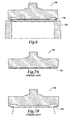
- FIG. 7A and 7B sectional views of a conventional prior art disc 700 of a prior art pressure relief valve used in a high temperature (e.g., steam) application is illustrated.
- the disc 700 includes lips 705 extending from a bottom surface of the disc 700 and directed towards a centerline of the disc 700.
- FIG. 6 shows the disc 700 in a non-operational state, i.e., with no high temperature fluid flowing through the valve in which the disc 700 is placed.
- a temperature gradient occurs across the lips 705 (e.g., high temperature at an inlet of the valve compared to ambient temperature at an outlet of the valve).
- FIG. 7B illustrates a deflection of the lips 705 due to the temperature gradient and thermal characteristics of the disc 700. As illustrated, due to a high temperature fluid, the lips 705 deflect in the direction "X.” Such deflection may help seal the valve (i.e., cause the disc to seat on a nozzle in the valve) to leaks, such as microleaks and/or macroleaks.
- a prior art pressure relief valve disc such as disc 135 (as shown in FIGS. 1A , 1B and 1C ) experiences micro or macroleaks when such a valve is placed in cryogenic service.
- Such prior art valve discs may also experience galling.
- galling is a form of surface damage on an interior surface of the pressure relief valve arising between sliding solids. Galling is, typically, distinct from damage caused by microscopic (usually localized) roughening and creation of protrusions ( i.e., lumps) above the interior surface. Galling may contribute or exacerbate the leaks experienced by the pressure relief valve due to the temperature difference experienced in cryogenic service.
- US 3,164,364 relates to a poppet-type valve for use in controlling the flow of steam to soot blowers and the like, the valve having a valve disk 30 which closes against a hardened valve seat surface 21, with movement of the valve disk caused by pivoting of a trigger 43 which is pivotally connected to the outside of the valve body and a yoke 46 to thereby vertically displace a valve stem 31, the valve disk 30 fixed to an end of the valve stem.
- the PRV of the present disclosure includes a disc-nozzle combination that minimizes and/or prevents process fluid leakage therethrough by deflection of portions of the disc and/or nozzle due to a thermal gradient between the process fluid temperature and the ambient condition.
- the disc of the PRV may include a groove disposed on an outer circumferential surface of the disc, thereby forming a protrusion (e.g., a lip) that deflects axially (rather than or in addition to radially) in order to sealingly contact the nozzle (as explained more fully below).
- the nozzle may include a notch disposed in an exterior circumferential surface of the nozzle to form a protrusion (e.g., a ledge) that, in response to a thermal gradient between the process fluid and the ambient condition on the outlet of the PRV, said ledge deflects to sealingly contact the disc and minimize and/or prevent leaks.
- a protrusion e.g., a ledge
- PRVs of the present disclosure may include one or more of the following features.
- the PRV may help prevent or minimize leaks during cryogenic service of the valve.
- the PRV may help prevent or minimize such leaks subsequent to a first opening (or "pop") of the valve in use in cryogenic service.
- the PRV may be used in a wide variety of cryogenic services and fluid temperatures while minimizing and/or preventing leaks through the valve caused at least in part by a temperature difference between the process fluid circulating through the valve and an ambient temperature condition in the valve (e.g., temperature on an outlet side of the PRV).
- the PRV may maximize set tightness during cryogenic service of the valve.
- the PRV may also utilize thermal characteristics of a material used for a valve disk and/or nozzle to minimize and/or prevent leaks of the valve during cryogenic service.
- the PRV may utilize a material deflection caused by a thermal gradient across the disc and/or nozzle to minimize and/or prevent leaks between the disk and nozzle.
- the PRV may utilize the thermal characteristics with a geometry of the disc and/or nozzle in order to minimize and/or prevent leaks between the disc and nozzle.
- one or more components of the PRV may axially deflect, rather than radially deflect, to sealingly contact and close the PRV to fluid flow therethrough in order to minimize and/or prevent leaks of the process fluid through the PRV.
- a pressure relief valve may include a disc, a disc holder, a nozzle, and a mass-spring-damper system that allows for a fluid (e.g., gas, liquid, or multiphase fluid) within a system, such as a piping system or pressure vessel, to be relieved by operation of the PRV when the fluidic pressure of the fluid exceeds a predetermined threshold.
- a fluid e.g., gas, liquid, or multiphase fluid
- the PRV may be used for cryogenic service, where a process fluid circulated to the PRV is at a lower temperature than an ambient condition at an outlet of the PRV.
- “Cryogenic service,” when used in the present disclosure, refers to applications in which a temperature of the process fluid circulated to the PRV is within one of the following temperature ranges: -29.4°C to -59.4°C (-21 to -75F) (e.g., propane as the process fluid); -60°C to -101 °C (-76 to -150F) (e.g., ethylene as the process fluid); and -102°C to -268°C (-151 to -450F) (e.g., liquefied natural gas " LNG", liquid nitrogen, liquid hydrogen or liquid helium as the process fluid).
- LNG liquid nitrogen, liquid hydrogen or liquid helium
- cryogenic service may refer to other temperature ranges for a combination of the aforementioned process fluids and other process fluid, such as: -17.8°C to - 45.6°C (0 to -50°F); -45.6°C to -101°C (-50 to -150°F); and -101°C to -268°C (-150 to -450°F).
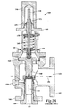
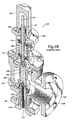
- FIGS. 1A-B illustrate sectional views of one implementation of a prior art pressure relief valve (PRV) 100.
- FIG. 1C illustrates a sectional view of another implementation of a pressure relief valve (PRV) 1000 having an alternative nozzle 121 integral with the base 105.
- PRV 100 receives a fluid 101 (e.g., gas or liquid or a multiphase fluid) at and through an inlet 110 and directs the fluid 101 to and through an outlet 115 of the PRV 100 in order to relieve a pressure within a system.
- a fluid 101 e.g., gas or liquid or a multiphase fluid
- the PRV 100 is typically in fluid communication with components, such as pressure vessels, heat exchangers, mechanical equipment (e.g., compressors, turbines, and others) within a piping or conduit system and may be used to control or limit a pressure in such a system, including such vessels, heat exchangers, and/or equipment, which can build up by a process upset, instrument or equipment failure, fire, or other incident.
- Pressure is relieved through the operation of PRV 100 by allowing the pressurized fluid to flow from the inlet 110 through the outlet 115 at a predetermined pressure set point.
- the PRV 100 may be designed or set to open at a predetermined set pressure to protect pressure vessels and other equipment from being subjected to pressures that exceed their design limits.
- the process fluid 101 may be one of a number of fluids utilized in cryogenic service.
- the fluid 101 may be methane, propane, ethylene, LNG, liquid nitrogen, or any combination thereof or other fluid.
- a temperature of the fluid 101 flowing through the inlet 110 may be substantially lower than an ambient temperature condition at the outlet 115.
- the ambient temperature typically, is between 10°C to 32.2°C (50-90°F).
- PRV 100 includes a base 105 at least partially enclosing a nozzle 120 (or, alternatively, PRV 1000 includes a base 105 with an integral nozzle 121 (see FIG. 1C )), and enclosing a disc 135, and a disc holder 140, and optionally an adjusting ring 125.
- the base 105 receives (e.g., threadingly or welded or integral) the nozzle 120 at the inlet 110 of the PRV 100 and, in the illustrated embodiment FIG. 1A and 1B , includes a flanged connection at the outlet 115.
- the nozzle 120 (or 121) generally, may be a pressure containing component in constant contact with the fluid 101 in both the open and closed positions of PRV 100. (Note: The nozzle 120 or 121 may sometimes be referred to in the art as a seat or seat bushing.)
- the base 105 may also include a flanged connection at the inlet 110 or, alternatively, may include other connection mechanisms (e.g., grooved pipe connection, butt weld, or otherwise) at one or both of the inlet 110 and outlet 115.
- a portion of the base 105 adjacent the outlet 115 may have a lower pressure rating than a portion of the base 105 adjacent the inlet 110 because of, for example, a decrease in fluidic pressure of the fluid 101 at the outlet 115 relative to the inlet 110.
- PRV 100 also includes a cap 180 and a bonnet 145 enclosing (at least partially) a spindle 160, which is threadingly engaged through one or more of a lock nut 185, an adjusting screw 175, spring washers 170, a spring 165, and a spindle head 155.
- the bonnet 145 is mechanically coupled (e.g., by one or more bolts and locking nuts or by threading) at one end to the base 105 while the cap 180 is mechanically coupled (e.g., threadingly) to the bonnet 145 at a second end.
- the PRV 100 also includes a guide 150 that receives at least a portion of the disc holder 140 therethrough.
- the disc 135, disc holder 140, spring washer (or washers) 170, spindle 160, spindle head 155, and spring 165 comprise a "mass-spring-damper" system that works to respond to fluidic forces applied by the fluid 101 as it contacts the disc 135 through the nozzle 120.
- the disc holder 140 includes a receiving aperture at a top end to receivingly engage the spindle head 155 such that force may be transmitted from the disc holder 140 to the spindle head 155 and, thus, to the spring washers 170 and spring 165.
- the spring 165 may be compressed, thereby urging the spindle 160 upward through the adjusting screw 175.
- the spring 165 expands, thereby urging the spindle 160 (and spindle head 155, disc holder 140, and disc 135) downward.
- an adjusting ring 125 is engaged (e.g., threadingly) with a top portion of the nozzle 120.
- adjusting ring 125 may be adjusted upward and/or downward on the nozzle 120 by threading or unthreading the ring 125 on the nozzle 120.
- blowdown, or reseating pressure may also be adjusted. For example, when the adjusting ring 125 is moved upward, blowdown is increased thereby lowering the reseating pressure.
- the adjusting ring 125 when the adjusting ring 125 is moved downward, the blowdown is decreased, thereby raising the reseating pressure.
- the adjusting ring 125, and therefore the PRV 100 may be preset at a predetermined position prior to putting the PRV 100 in service. In such embodiments, presetting may reduce the necessity of "popping" (i.e., applying the set pressure to the PRV 100, such that significant lift of the disc and/or disc holder is obtained) the PRV 100 in service to ascertain that the adjusting ring 125 has been set properly for attaining the necessary lift and relieving capacity.
- a ring pin 130 extends from a location external to the base 105, through the base 105, and operates to secure the adjusting ring 125 at a certain location (e.g., vertical position) on the nozzle 120.
- the adjusting ring 125 may be adjusted (i.e., moved upward or downward).
- the adjusting ring 125 may have multiple vertical grooves arranged circumferentially around an outer surface of the ring 125.
- the adjusting ring 125 has 30 grooves; alternatively, the adjusting ring 125 may have fewer or more grooves (e.g., 16, 42, or other number of grooves).
- the ring pin 130 includes a pointed tip configured to fit within a groove (e.g., approximately halfway between peaks and a valley between two grooves) and substantially prevents the adjusting ring 125 from vertical movement along the nozzle 120 through rotation of the adjusting ring 125 around the nozzle 120.
- adjusting the ring pin 130 between adjacent grooves may allow for approximately 12 degrees of rotation of the adjusting ring 125, which translates to approximately 0.0508 mm (2/1000 inch) vertical movement of the adjusting ring 125 along the nozzle 120.
- the PRV 100 is in a "closed” state, where the disc 135 is "seated” on the nozzle 120.
- PRV 1000 is illustrated in a closed state in FIG. 1C and FIG. ID.
- flow of the fluid 101 may be prevented or substantially prevented from the inlet 110 to the outlet 115 of the PRV 100.
- the PRV 100 may experience a leak such that a small flow of fluid 101 occurs from the inlet 110 to the outlet 115.
- a thermal gradient may occur across the disc 135 and/or nozzle 120.
- the thermal gradient may occur across a portion of the disc 135 that contacts the nozzle 120, e.g., a "seat.”
- Such a thermal gradient across a disc and/or nozzle may cause a thermal deflection of one or both of these components, thereby exacerbating the leak (or preventing the disc from seating on the nozzle).
- This thermal deflection may, for example, cause a radial deflection of the disc (e.g., radially outward from a vertical centerline of the valve), thereby increasing a gap between the disc and nozzle.
- the gap may allow fluid 101 to flow to the outlet 115 during a leak.
- a disc 200 and/or nozzle 300 for use in the prior art PRV 100 to thermally deflect in an axial direction toward each other (i.e., vertically in parallel with a centerline 10 defined through the PRV 100 as shown in FIG. 4 ).
- the disc 200 may axially deflect towards a seat 119 of the nozzle 300, thereby closing or substantially closing the PRV 100 to prevent or substantially prevent flow of the fluid 101 from the inlet 110 to the outlet 115 in cryogenic service.
- a portion of the nozzle 300 may deflect axially towards the disc 300 to assist in closing the PRV 100.
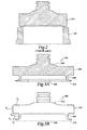
- FIGS. 3A and 3B illustrate a sectional view of the disc 200 that may be used in the PRV 100 of the present disclosure.
- the disc 200 has a body 210, a lip 215, a groove ring 220, and a groove cut 225.
- at least a portion of the disc 200 may axially deflect in the illustrated direction "Z" in response to a thermal gradient across the lip 215.
- a thermal gradient between the inlet 110 and the outlet 120 of the PRV 100 may occur across the lip 215 of the disc 200.
- the thermal gradient may, in some embodiments, be dependent on the difference between a temperature of the fluid 101 at the inlet 110 of the PRV and an ambient temperature at the outlet 115 of the PRV.
- position P 1 illustrates the configuration of an embodiment of the disc 200 when not deflected due to a thermal gradient.
- Position P 2 illustrates a deflected position due to a thermal gradient across the disc 200. Dotted lines illustrate the approximated deflected position P 2 . The amount of deflection will vary depending on the thermal gradient and the configuration of the disc 200.
- the groove ring 220 may be a circumferential recess in the body 210 around an exterior, radial surface 230 of the disc 200. Further, in the illustrated embodiment of the disc 200, the groove cut 225 may be formed in a bottom surface of the body 210. In forming the groove ring 220 and the groove cut 225 in the body 210 of the disc 200, the lip 215 may be configured to extend away from the body 210 in response to the thermal gradient.
- the groove ring 220 and groove cut 225 may minimize and/or reduce a thermal mass of the body 210 of the disc 200. For instance, by forming the groove ring 220 and groove cut 225 in the body 210 of the disc 200, thermal mass may be removed in order to minimize thermal mass around the lip 215. In some embodiments, this minimization of thermal mass may direct and/or confine the thermal gradient across the lip 215 rather than, for example, other portions of the body 210. Due to the reduction of thermal mass by the groove ring 220 and/or groove cut 225, thermal deflection in a radial direction (e.g., radially towards the exterior surface 230) of the body 215 may be minimized and/or prevented.
- a radial direction e.g., radially towards the exterior surface 230
- the groove cut 225 also reduces the section modulus of the disc at the lip which increases the thermally induced deflection in the axial direction.
- Thermal deflection as shown in FIG. 3B , may therefore be confined or directed in the "Z" direction, deflecting the lip 215 substantially axially toward the nozzle (not shown here).
- the lip 215 By confining and/or directing the thermal deflection of the disc 200 due to the thermal gradient in a substantially axial direction, "Z,” the lip 215 may be urged into contact with the nozzle to close or substantially close the PRV 100 against leaks of the fluid 101 from the inlet 110 to the outlet 115.
- the disc 200 may be manufactured from a material with a relatively high coefficient of thermal expansion.
- the disc 200 may be made from 316 stainless steel.
- the disc 200 may be made from Inconel X-750, or another alloy, such as Incoloy 903, Incoloy 907, Incoloy 909, Inconel X-783, or other alloy(s) suitable for cryogenic applications with a relatively high coefficient of thermal expansion.
- FIG. 4 illustrates a sectional view of a disc and a nozzle combination used in one implementation of the PRV 100.
- disc 200 may be used in combination with a nozzle 300 in the PRV 100 to regulate flow of the fluid 101 from the inlet 110 to the outlet 115 of the PRV 100.
- the nozzle 300 includes a ledge 305 formed at a top surface of the nozzle 300 (i.e., seat 119).
- the ledge 305 may be formed in the nozzle 300 to protrude radially towards the centerline 10 of the PRV 100 by, for example, formation of a recess in an exterior surface 315 of the nozzle 300 to form a radial notch 310.
- the thermal gradient between the inlet 110 and the outlet 120 of the PRV 100 may be experienced across the ledge 305.
- the radial notch 310 may minimize and/or reduce a thermal mass of the nozzle 300 at the seat 119. For instance, by forming the radial notch 310, thermal mass may be removed in order to minimize thermal mass around the ledge 305. In some embodiments, this minimization of thermal mass may direct and/or confine the thermal gradient across the ledge 310 rather than, for example, a full thickness of the seat 119 between the interior surface 315 and an exterior surface 320.
- thermal deflection in a radial direction e.g., towards the interior surface 315) of the seat 119 may be minimized and/or prevented.
- Thermal deflection may therefore be confined to or directed in an axial direction, deflecting the ledge 305 toward the disc 200.
- the ledge 305 may be urged into contact with the disc 200 to close or substantially close the PRV 100 against leaks of the fluid 101 from the inlet 110 to the outlet 115.
- the nozzle 300 may be manufactured from a material with a relatively high coefficient of thermal expansion.
- the nozzle 300 may be made from 316 stainless steel.
- the nozzle 300 may be made from Inconel X-750, or another alloy, such as Incoloy 903, Incoloy 907, Incoloy 909, Inconel X-783, or other alloy(s) suitable for cryogenic application with a relatively high coefficient of thermal expansion.
- FIGS. 5A and 5B illustrate a sectional view of a disc 400 that may be used in the PRV 100 of the present disclosure.
- the disc 400 has a body 410, a lip 415, and a groove ring 420.
- at least a portion of the disc 400 may axially deflect in the illustrated direction "Z" in response to a thermal gradient across the lip 415.
- a thermal gradient between the inlet 110 and the outlet 120 of the PRV 100 may be experienced across the lip 415 of the disc 400.
- the thermal gradient may, in some embodiments, be a difference between a temperature of the fluid 101 at the inlet 110 of the PRV and an ambient temperature at the outlet 115 of the PRV.
- position P 1 illustrates the configuration of an embodiment of the disc 400 when not deflected due to a thermal gradient.
- Position P 2 illustrates a deflected position due to a thermal gradient across the disc 400. Dotted lines illustrate the approximated deflected position P 2 . The amount of deflection will vary depending on the thermal gradient and the configuration of the disc 400.
- the groove ring 420 may be a circumferential recess in the body 410 around an exterior, radial surface 430 of the disc 400. As compared to the disc 200 (shown in FIG. 3A ), the disc 400 may not have a groove cut formed in a bottom surface of the disc 400. In forming the groove ring 420 in the body 410 of the disc 400, the lip 415 may be formed to deflect away from the body 410 in response to the thermal gradient.
- the groove ring 420 may minimize and/or reduce a thermal mass of the body 410 of the disc 400. For instance, by forming the groove ring 420 in the body 410 of the disc 400, thermal mass may be removed in order to minimize thermal mass around the lip 415. In some embodiments, this minimization of thermal mass may direct and/or confine the thermal gradient across the lip 415 rather than, for example, other portions of the body 410 (e.g., the full radial thickness of the body 410). Due to the reduction of thermal mass by the groove ring 420, thermal deflection in a radial direction (e.g., radially towards the exterior surface 430) of the body 415 may be minimized and/or prevented.
- a radial direction e.g., radially towards the exterior surface 430
- Thermal deflection may therefore be confined or directed in the "Z" direction, deflecting the lip 415 substantially axially toward the nozzle (not shown here).
- the lip 415 may be urged into contact with the nozzle to close or substantially close the PRV 100 against leaks of the fluid 101 from the inlet 110 to the outlet 115.
- Test fluid Liquid Nitrogen; Fluid Temperature: -305 F to -285 F Standard Trim Cryogenic Trim % improvement Set Pressure Leak stop % set pressure Set pressure Leak stop % set pressure 1900J 97.1 38.6 39.7% 95 76.4 79.8% 201% 1900F 107 39.6 37 . 0% 108 75.4 69 . 8% 189%
- the percentage improvement is calculated as the improvement in the leak pressure/set pressure ratio of the cryogenic trim over the standard trim.
- the PRV 100 may include varying disc-nozzle combinations.
- the disc 200 may be combined with the nozzle 300 as shown in FIG. 4 .
- the disc 400 may be combined with the nozzle 300.
- the disc 200 may be combined with a conventional nozzle, such as the nozzle 120, which, in some embodiments, may not include the radial notch 310 and/or ledge 305.
- the disc 400 may be combined with the nozzle 120.
- the nozzle 300 may be combined with a conventional disc, which may not include a groove cut, a groove ring, or a lip as those components of the disc are illustrated in the present disclosure.
- Different combinations may provide for varying operation of the PRV 100.
- combining the disc 200 with the nozzle 300 may provide for maximal sealing contact between the lip 215 and the ledge 305, as axial thermal deflection due to a thermal gradient across the lip 215 and ledge 305 may urge the disc 200 and nozzle 300 into sealing contact.
- the present disclosure contemplates many different embodiments with varying combinations of the disc, nozzle, and other components of the PRV depending on, for example, a temperature of the fluid 101 and/or cryogenic service in which the PRV 100 is used.
- the recess of the groove ring 220 and/or 420 in an outer surface of the disc 200 and/or 420 may have a cross sectional profile that is hemispherical, square, or v-shaped. Accordingly, other implementations are within the scope of the following claims.
Landscapes
- Engineering & Computer Science (AREA)
- General Engineering & Computer Science (AREA)
- Mechanical Engineering (AREA)
- Filling Or Discharging Of Gas Storage Vessels (AREA)
- Lift Valve (AREA)
- Safety Valves (AREA)
Applications Claiming Priority (2)
| Application Number | Priority Date | Filing Date | Title |
|---|---|---|---|
| US12/981,028 US8505572B2 (en) | 2010-12-29 | 2010-12-29 | Pressure relief valve |
| PCT/US2011/065087 WO2012091937A1 (en) | 2010-12-29 | 2011-12-15 | Pressure relief valve |
Publications (2)
| Publication Number | Publication Date |
|---|---|
| EP2659171A1 EP2659171A1 (en) | 2013-11-06 |
| EP2659171B1 true EP2659171B1 (en) | 2015-04-15 |
Family
ID=45464896
Family Applications (1)
| Application Number | Title | Priority Date | Filing Date |
|---|---|---|---|
| EP20110806083 Active EP2659171B1 (en) | 2010-12-29 | 2011-12-15 | Pressure relief valve |
Country Status (5)
| Country | Link |
|---|---|
| US (2) | US8505572B2 (cg-RX-API-DMAC10.html) |
| EP (1) | EP2659171B1 (cg-RX-API-DMAC10.html) |
| JP (1) | JP5986583B2 (cg-RX-API-DMAC10.html) |
| CN (1) | CN103348169B (cg-RX-API-DMAC10.html) |
| WO (1) | WO2012091937A1 (cg-RX-API-DMAC10.html) |
Families Citing this family (9)
| Publication number | Priority date | Publication date | Assignee | Title |
|---|---|---|---|---|
| US9856794B2 (en) | 2012-10-23 | 2018-01-02 | Hamilton Sundstrand Corporation | High pressure relief valve nozzle |
| JP5790674B2 (ja) * | 2013-02-01 | 2015-10-07 | 株式会社デンソー | リリーフ弁装置 |
| CN104913089B (zh) * | 2015-06-01 | 2017-07-04 | 杭州华惠阀门有限公司 | 一种安全阀 |
| US10738903B2 (en) | 2018-08-29 | 2020-08-11 | International Business Machines Corporation | Microfluidic relief valve |
| US11598436B2 (en) | 2021-04-14 | 2023-03-07 | Dresser, Llc | Safety valves for use at extremely high temperatures |
| US11959557B2 (en) * | 2022-08-31 | 2024-04-16 | Dresser, Llc | Preventing damage to valves due to cold weather |
| US12504083B2 (en) * | 2023-04-13 | 2025-12-23 | Curtiss-Wright Flow Control Corporation | Relief valve |
| WO2025188591A1 (en) * | 2024-03-04 | 2025-09-12 | Curtiss-Wright Flow Control Corporation | Low pressure relief valve |
| CN120426428B (zh) * | 2025-07-08 | 2025-09-19 | 中国重型机械研究院股份公司 | 一种绝热防焦的耐高温泄爆阀、制作及泄爆方法 |
Family Cites Families (28)
| Publication number | Priority date | Publication date | Assignee | Title |
|---|---|---|---|---|
| US1671140A (en) * | 1926-01-25 | 1928-05-29 | Wylie G Wilson | Valve |
| US1671139A (en) * | 1926-01-25 | 1928-05-29 | Wylie G Wilson | Valve |
| US1699217A (en) * | 1926-04-24 | 1929-01-15 | Wylie G Wilson | Valve |
| US2643671A (en) | 1952-06-21 | 1953-06-30 | Manning Maxwell & Moore Inc | Spring loaded pop-safety valve |
| US3174718A (en) | 1961-11-17 | 1965-03-23 | Manning Maxwell & Moore Inc | Valve with improved head seal |
| US3141474A (en) * | 1962-08-15 | 1964-07-21 | Perry H Gentzel | Safety valve construction |
| US3164364A (en) * | 1962-10-04 | 1965-01-05 | Diamond Power Speciality | Deformable valve head and seat construction |
| US3450385A (en) | 1966-12-12 | 1969-06-17 | Rockwell Mfg Co | Grooved valve disc |
| GB1164678A (en) | 1966-12-27 | 1969-09-17 | Toa Valve Company Ltd | Improvements relating to Pop Safety Valves |
| US3902695A (en) | 1973-12-13 | 1975-09-02 | Us Energy | Valve for cryogenic service |
| US4130130A (en) | 1976-11-15 | 1978-12-19 | Crosby Valve & Gage Company | Valve with variable secondary orifice |
| US4357956A (en) | 1980-08-12 | 1982-11-09 | Bopp & Reuther Gmbh | Safety valve with vibration-damped valve spring |
| DE3210768C2 (de) | 1982-03-24 | 1990-07-12 | Bopp & Reuther Gmbh, 6800 Mannheim | Sicherheitsventil mit einer Reibeinrichtung zum Unterdrücken von Ventilschwingungen |
| FR2524958B1 (fr) * | 1982-04-07 | 1986-02-07 | Sarasin & Cie Ets | Soupape de surete |
| US4595033A (en) | 1983-09-30 | 1986-06-17 | Dresser Industries, Inc. | Low pressure high temperature safety valve |
| US4708164A (en) * | 1986-06-16 | 1987-11-24 | Dresser Industries, Inc. | Safety relief valve |
| US4757974A (en) * | 1987-04-13 | 1988-07-19 | Ward Erin C | Check valve |
| DE3713974A1 (de) | 1987-04-25 | 1988-11-10 | Sempell Rhein Armaturen | Federbelastetes sicherheitsventil |
| US4858642A (en) * | 1988-01-25 | 1989-08-22 | Dresser Industries, Inc. | Impact resistant pressure relief valve |
| US4932434A (en) * | 1988-01-25 | 1990-06-12 | Taylor Wesley L | Adjustable safety relief valve |
| SE467708B (sv) | 1990-03-27 | 1992-08-31 | Stal Refrigeration Ab | Tryckkontrollventil |
| US5046524A (en) | 1990-07-23 | 1991-09-10 | Dresser Industries, Inc. | Safety relief valve |
| US5370151A (en) | 1994-03-23 | 1994-12-06 | Dresser Industries Inc. | Safety valve |
| US5515884A (en) | 1994-05-18 | 1996-05-14 | Dresser Industries Inc. | Multi-media safety relief valve |
| US5791373A (en) * | 1996-04-29 | 1998-08-11 | Adams; John S. | Fluid sealing disc and seat mechanism |
| CN100540961C (zh) * | 2007-12-14 | 2009-09-16 | 苏州有色金属研究院有限公司 | 气缸式喷射阀 |
| US8360095B2 (en) * | 2008-02-01 | 2013-01-29 | Exxonmobil Chemical Patents Inc. | High-pressure valve |
| US8607818B2 (en) * | 2010-05-20 | 2013-12-17 | Dresser, Inc. | Pressure relief valve |
-
2010
- 2010-12-29 US US12/981,028 patent/US8505572B2/en active Active
-
2011
- 2011-12-15 CN CN201180063324.4A patent/CN103348169B/zh not_active Expired - Fee Related
- 2011-12-15 EP EP20110806083 patent/EP2659171B1/en active Active
- 2011-12-15 WO PCT/US2011/065087 patent/WO2012091937A1/en not_active Ceased
- 2011-12-15 JP JP2013547519A patent/JP5986583B2/ja active Active
-
2013
- 2013-07-03 US US13/934,643 patent/US9273788B2/en active Active
Also Published As
| Publication number | Publication date |
|---|---|
| US20140000728A1 (en) | 2014-01-02 |
| WO2012091937A1 (en) | 2012-07-05 |
| US8505572B2 (en) | 2013-08-13 |
| JP2014501375A (ja) | 2014-01-20 |
| EP2659171A1 (en) | 2013-11-06 |
| US9273788B2 (en) | 2016-03-01 |
| CN103348169A (zh) | 2013-10-09 |
| US20120167992A1 (en) | 2012-07-05 |
| CN103348169B (zh) | 2015-07-01 |
| JP5986583B2 (ja) | 2016-09-06 |
Similar Documents
| Publication | Publication Date | Title |
|---|---|---|
| US9273788B2 (en) | Pressure relief valve | |
| EP3859195B1 (en) | Extremely low-temperature globe valve | |
| US8607818B2 (en) | Pressure relief valve | |
| US4932434A (en) | Adjustable safety relief valve | |
| US8398053B2 (en) | Double piston trunnion mounted ball valves and methods of use | |
| US6698715B2 (en) | Valve having ceramic components and associated fabrication method | |
| AU682605B2 (en) | Multi-media safety relief valve | |
| US9395019B2 (en) | Device for sealing a valve | |
| US20010038084A1 (en) | Valve having ceramic components and associated fabrication method | |
| JP2005321061A (ja) | 高温用弁 | |
| CN102369377B (zh) | 压力平衡控制阀 | |
| JP7562877B2 (ja) | 極めて高温で使用するための安全弁の改良 | |
| KR102418912B1 (ko) | 팝핑 기능을 구비한 릴리프 밸브 | |
| CN118257868A (zh) | 一种分段式反冲盘的弹簧式低温安全阀 | |
| JP7574727B2 (ja) | シール構造および弁装置 | |
| AU2005238872A1 (en) | Low pressure stem gas seal | |
| JP2025039309A (ja) | エクステンションボンネット型回転弁 |
Legal Events
| Date | Code | Title | Description |
|---|---|---|---|
| PUAI | Public reference made under article 153(3) epc to a published international application that has entered the european phase |
Free format text: ORIGINAL CODE: 0009012 |
|
| 17P | Request for examination filed |
Effective date: 20130729 |
|
| AK | Designated contracting states |
Kind code of ref document: A1 Designated state(s): AL AT BE BG CH CY CZ DE DK EE ES FI FR GB GR HR HU IE IS IT LI LT LU LV MC MK MT NL NO PL PT RO RS SE SI SK SM TR |
|
| DAX | Request for extension of the european patent (deleted) | ||
| 17Q | First examination report despatched |
Effective date: 20140530 |
|
| GRAP | Despatch of communication of intention to grant a patent |
Free format text: ORIGINAL CODE: EPIDOSNIGR1 |
|
| INTG | Intention to grant announced |
Effective date: 20141215 |
|
| GRAS | Grant fee paid |
Free format text: ORIGINAL CODE: EPIDOSNIGR3 |
|
| GRAA | (expected) grant |
Free format text: ORIGINAL CODE: 0009210 |
|
| AK | Designated contracting states |
Kind code of ref document: B1 Designated state(s): AL AT BE BG CH CY CZ DE DK EE ES FI FR GB GR HR HU IE IS IT LI LT LU LV MC MK MT NL NO PL PT RO RS SE SI SK SM TR |
|
| REG | Reference to a national code |
Ref country code: GB Ref legal event code: FG4D Ref country code: CH Ref legal event code: EP |
|
| REG | Reference to a national code |
Ref country code: IE Ref legal event code: FG4D |
|
| REG | Reference to a national code |
Ref country code: AT Ref legal event code: REF Ref document number: 722193 Country of ref document: AT Kind code of ref document: T Effective date: 20150515 |
|
| REG | Reference to a national code |
Ref country code: DE Ref legal event code: R096 Ref document number: 602011015766 Country of ref document: DE Effective date: 20150528 |
|
| REG | Reference to a national code |
Ref country code: NL Ref legal event code: T3 |
|
| REG | Reference to a national code |
Ref country code: AT Ref legal event code: MK05 Ref document number: 722193 Country of ref document: AT Kind code of ref document: T Effective date: 20150415 |
|
| REG | Reference to a national code |
Ref country code: LT Ref legal event code: MG4D |
|
| PG25 | Lapsed in a contracting state [announced via postgrant information from national office to epo] |
Ref country code: FI Free format text: LAPSE BECAUSE OF FAILURE TO SUBMIT A TRANSLATION OF THE DESCRIPTION OR TO PAY THE FEE WITHIN THE PRESCRIBED TIME-LIMIT Effective date: 20150415 Ref country code: PT Free format text: LAPSE BECAUSE OF FAILURE TO SUBMIT A TRANSLATION OF THE DESCRIPTION OR TO PAY THE FEE WITHIN THE PRESCRIBED TIME-LIMIT Effective date: 20150817 Ref country code: NO Free format text: LAPSE BECAUSE OF FAILURE TO SUBMIT A TRANSLATION OF THE DESCRIPTION OR TO PAY THE FEE WITHIN THE PRESCRIBED TIME-LIMIT Effective date: 20150715 Ref country code: ES Free format text: LAPSE BECAUSE OF FAILURE TO SUBMIT A TRANSLATION OF THE DESCRIPTION OR TO PAY THE FEE WITHIN THE PRESCRIBED TIME-LIMIT Effective date: 20150415 Ref country code: LT Free format text: LAPSE BECAUSE OF FAILURE TO SUBMIT A TRANSLATION OF THE DESCRIPTION OR TO PAY THE FEE WITHIN THE PRESCRIBED TIME-LIMIT Effective date: 20150415 Ref country code: HR Free format text: LAPSE BECAUSE OF FAILURE TO SUBMIT A TRANSLATION OF THE DESCRIPTION OR TO PAY THE FEE WITHIN THE PRESCRIBED TIME-LIMIT Effective date: 20150415 |
|
| PG25 | Lapsed in a contracting state [announced via postgrant information from national office to epo] |
Ref country code: RS Free format text: LAPSE BECAUSE OF FAILURE TO SUBMIT A TRANSLATION OF THE DESCRIPTION OR TO PAY THE FEE WITHIN THE PRESCRIBED TIME-LIMIT Effective date: 20150415 Ref country code: AT Free format text: LAPSE BECAUSE OF FAILURE TO SUBMIT A TRANSLATION OF THE DESCRIPTION OR TO PAY THE FEE WITHIN THE PRESCRIBED TIME-LIMIT Effective date: 20150415 Ref country code: LV Free format text: LAPSE BECAUSE OF FAILURE TO SUBMIT A TRANSLATION OF THE DESCRIPTION OR TO PAY THE FEE WITHIN THE PRESCRIBED TIME-LIMIT Effective date: 20150415 Ref country code: IS Free format text: LAPSE BECAUSE OF FAILURE TO SUBMIT A TRANSLATION OF THE DESCRIPTION OR TO PAY THE FEE WITHIN THE PRESCRIBED TIME-LIMIT Effective date: 20150815 Ref country code: GR Free format text: LAPSE BECAUSE OF FAILURE TO SUBMIT A TRANSLATION OF THE DESCRIPTION OR TO PAY THE FEE WITHIN THE PRESCRIBED TIME-LIMIT Effective date: 20150716 |
|
| REG | Reference to a national code |
Ref country code: FR Ref legal event code: PLFP Year of fee payment: 5 |
|
| REG | Reference to a national code |
Ref country code: DE Ref legal event code: R097 Ref document number: 602011015766 Country of ref document: DE |
|
| PG25 | Lapsed in a contracting state [announced via postgrant information from national office to epo] |
Ref country code: DK Free format text: LAPSE BECAUSE OF FAILURE TO SUBMIT A TRANSLATION OF THE DESCRIPTION OR TO PAY THE FEE WITHIN THE PRESCRIBED TIME-LIMIT Effective date: 20150415 Ref country code: EE Free format text: LAPSE BECAUSE OF FAILURE TO SUBMIT A TRANSLATION OF THE DESCRIPTION OR TO PAY THE FEE WITHIN THE PRESCRIBED TIME-LIMIT Effective date: 20150415 |
|
| PLBE | No opposition filed within time limit |
Free format text: ORIGINAL CODE: 0009261 |
|
| STAA | Information on the status of an ep patent application or granted ep patent |
Free format text: STATUS: NO OPPOSITION FILED WITHIN TIME LIMIT |
|
| PG25 | Lapsed in a contracting state [announced via postgrant information from national office to epo] |
Ref country code: CZ Free format text: LAPSE BECAUSE OF FAILURE TO SUBMIT A TRANSLATION OF THE DESCRIPTION OR TO PAY THE FEE WITHIN THE PRESCRIBED TIME-LIMIT Effective date: 20150415 Ref country code: RO Free format text: LAPSE BECAUSE OF NON-PAYMENT OF DUE FEES Effective date: 20150415 Ref country code: PL Free format text: LAPSE BECAUSE OF FAILURE TO SUBMIT A TRANSLATION OF THE DESCRIPTION OR TO PAY THE FEE WITHIN THE PRESCRIBED TIME-LIMIT Effective date: 20150415 Ref country code: SK Free format text: LAPSE BECAUSE OF FAILURE TO SUBMIT A TRANSLATION OF THE DESCRIPTION OR TO PAY THE FEE WITHIN THE PRESCRIBED TIME-LIMIT Effective date: 20150415 |
|
| 26N | No opposition filed |
Effective date: 20160118 |
|
| PG25 | Lapsed in a contracting state [announced via postgrant information from national office to epo] |
Ref country code: SI Free format text: LAPSE BECAUSE OF FAILURE TO SUBMIT A TRANSLATION OF THE DESCRIPTION OR TO PAY THE FEE WITHIN THE PRESCRIBED TIME-LIMIT Effective date: 20150415 Ref country code: BE Free format text: LAPSE BECAUSE OF NON-PAYMENT OF DUE FEES Effective date: 20151231 |
|
| PG25 | Lapsed in a contracting state [announced via postgrant information from national office to epo] |
Ref country code: LU Free format text: LAPSE BECAUSE OF FAILURE TO SUBMIT A TRANSLATION OF THE DESCRIPTION OR TO PAY THE FEE WITHIN THE PRESCRIBED TIME-LIMIT Effective date: 20151215 Ref country code: MC Free format text: LAPSE BECAUSE OF FAILURE TO SUBMIT A TRANSLATION OF THE DESCRIPTION OR TO PAY THE FEE WITHIN THE PRESCRIBED TIME-LIMIT Effective date: 20150415 |
|
| REG | Reference to a national code |
Ref country code: CH Ref legal event code: PL |
|
| PG25 | Lapsed in a contracting state [announced via postgrant information from national office to epo] |
Ref country code: BE Free format text: LAPSE BECAUSE OF FAILURE TO SUBMIT A TRANSLATION OF THE DESCRIPTION OR TO PAY THE FEE WITHIN THE PRESCRIBED TIME-LIMIT Effective date: 20150415 |
|
| REG | Reference to a national code |
Ref country code: IE Ref legal event code: MM4A |
|
| PG25 | Lapsed in a contracting state [announced via postgrant information from national office to epo] |
Ref country code: LI Free format text: LAPSE BECAUSE OF NON-PAYMENT OF DUE FEES Effective date: 20151231 Ref country code: CH Free format text: LAPSE BECAUSE OF NON-PAYMENT OF DUE FEES Effective date: 20151231 Ref country code: IE Free format text: LAPSE BECAUSE OF NON-PAYMENT OF DUE FEES Effective date: 20151215 |
|
| REG | Reference to a national code |
Ref country code: FR Ref legal event code: PLFP Year of fee payment: 6 |
|
| PG25 | Lapsed in a contracting state [announced via postgrant information from national office to epo] |
Ref country code: IT Free format text: LAPSE BECAUSE OF NON-PAYMENT OF DUE FEES Effective date: 20151215 |
|
| PG25 | Lapsed in a contracting state [announced via postgrant information from national office to epo] |
Ref country code: SM Free format text: LAPSE BECAUSE OF FAILURE TO SUBMIT A TRANSLATION OF THE DESCRIPTION OR TO PAY THE FEE WITHIN THE PRESCRIBED TIME-LIMIT Effective date: 20150415 Ref country code: BG Free format text: LAPSE BECAUSE OF FAILURE TO SUBMIT A TRANSLATION OF THE DESCRIPTION OR TO PAY THE FEE WITHIN THE PRESCRIBED TIME-LIMIT Effective date: 20150415 Ref country code: HU Free format text: LAPSE BECAUSE OF FAILURE TO SUBMIT A TRANSLATION OF THE DESCRIPTION OR TO PAY THE FEE WITHIN THE PRESCRIBED TIME-LIMIT; INVALID AB INITIO Effective date: 20111215 |
|
| PG25 | Lapsed in a contracting state [announced via postgrant information from national office to epo] |
Ref country code: SE Free format text: LAPSE BECAUSE OF FAILURE TO SUBMIT A TRANSLATION OF THE DESCRIPTION OR TO PAY THE FEE WITHIN THE PRESCRIBED TIME-LIMIT Effective date: 20150415 Ref country code: CY Free format text: LAPSE BECAUSE OF FAILURE TO SUBMIT A TRANSLATION OF THE DESCRIPTION OR TO PAY THE FEE WITHIN THE PRESCRIBED TIME-LIMIT Effective date: 20150415 |
|
| PG25 | Lapsed in a contracting state [announced via postgrant information from national office to epo] |
Ref country code: MT Free format text: LAPSE BECAUSE OF FAILURE TO SUBMIT A TRANSLATION OF THE DESCRIPTION OR TO PAY THE FEE WITHIN THE PRESCRIBED TIME-LIMIT Effective date: 20150415 Ref country code: IT Free format text: LAPSE BECAUSE OF NON-PAYMENT OF DUE FEES Effective date: 20151215 |
|
| PGFP | Annual fee paid to national office [announced via postgrant information from national office to epo] |
Ref country code: IT Payment date: 20151222 Year of fee payment: 5 |
|
| PGRI | Patent reinstated in contracting state [announced from national office to epo] |
Ref country code: IT Effective date: 20170710 |
|
| PG25 | Lapsed in a contracting state [announced via postgrant information from national office to epo] |
Ref country code: IT Free format text: LAPSE BECAUSE OF NON-PAYMENT OF DUE FEES Effective date: 20161215 |
|
| PGRI | Patent reinstated in contracting state [announced from national office to epo] |
Ref country code: IT Effective date: 20170710 |
|
| REG | Reference to a national code |
Ref country code: FR Ref legal event code: PLFP Year of fee payment: 7 |
|
| PG25 | Lapsed in a contracting state [announced via postgrant information from national office to epo] |
Ref country code: MK Free format text: LAPSE BECAUSE OF FAILURE TO SUBMIT A TRANSLATION OF THE DESCRIPTION OR TO PAY THE FEE WITHIN THE PRESCRIBED TIME-LIMIT Effective date: 20150415 |
|
| PG25 | Lapsed in a contracting state [announced via postgrant information from national office to epo] |
Ref country code: AL Free format text: LAPSE BECAUSE OF FAILURE TO SUBMIT A TRANSLATION OF THE DESCRIPTION OR TO PAY THE FEE WITHIN THE PRESCRIBED TIME-LIMIT Effective date: 20150415 Ref country code: TR Free format text: LAPSE BECAUSE OF FAILURE TO SUBMIT A TRANSLATION OF THE DESCRIPTION OR TO PAY THE FEE WITHIN THE PRESCRIBED TIME-LIMIT Effective date: 20150415 |
|
| PGFP | Annual fee paid to national office [announced via postgrant information from national office to epo] |
Ref country code: NL Payment date: 20251119 Year of fee payment: 15 |
|
| PGFP | Annual fee paid to national office [announced via postgrant information from national office to epo] |
Ref country code: DE Payment date: 20251126 Year of fee payment: 15 |
|
| PGFP | Annual fee paid to national office [announced via postgrant information from national office to epo] |
Ref country code: GB Payment date: 20251119 Year of fee payment: 15 |
|
| PGFP | Annual fee paid to national office [announced via postgrant information from national office to epo] |
Ref country code: FR Payment date: 20251120 Year of fee payment: 15 |