EP2658278A2 - An isolated measurement system with cooperatively-timed isolated power generation - Google Patents
An isolated measurement system with cooperatively-timed isolated power generation Download PDFInfo
- Publication number
- EP2658278A2 EP2658278A2 EP13164191.2A EP13164191A EP2658278A2 EP 2658278 A2 EP2658278 A2 EP 2658278A2 EP 13164191 A EP13164191 A EP 13164191A EP 2658278 A2 EP2658278 A2 EP 2658278A2
- Authority
- EP
- European Patent Office
- Prior art keywords
- power
- measurement system
- measurement
- isolator
- signal
- Prior art date
- Legal status (The legal status is an assumption and is not a legal conclusion. Google has not performed a legal analysis and makes no representation as to the accuracy of the status listed.)
- Granted
Links
Images


Classifications
-
- H—ELECTRICITY
- H04—ELECTRIC COMMUNICATION TECHNIQUE
- H04Q—SELECTING
- H04Q9/00—Arrangements in telecontrol or telemetry systems for selectively calling a substation from a main station, in which substation desired apparatus is selected for applying a control signal thereto or for obtaining measured values therefrom
-
- H—ELECTRICITY
- H02—GENERATION; CONVERSION OR DISTRIBUTION OF ELECTRIC POWER
- H02J—CIRCUIT ARRANGEMENTS OR SYSTEMS FOR SUPPLYING OR DISTRIBUTING ELECTRIC POWER; SYSTEMS FOR STORING ELECTRIC ENERGY
- H02J1/00—Circuit arrangements for dc mains or dc distribution networks
- H02J1/02—Arrangements for reducing harmonics or ripples
-
- G—PHYSICS
- G06—COMPUTING; CALCULATING OR COUNTING
- G06F—ELECTRIC DIGITAL DATA PROCESSING
- G06F1/00—Details not covered by groups G06F3/00 - G06F13/00 and G06F21/00
- G06F1/26—Power supply means, e.g. regulation thereof
-
- H—ELECTRICITY
- H04—ELECTRIC COMMUNICATION TECHNIQUE
- H04Q—SELECTING
- H04Q2209/00—Arrangements in telecontrol or telemetry systems
- H04Q2209/80—Arrangements in the sub-station, i.e. sensing device
- H04Q2209/88—Providing power supply at the sub-station
- H04Q2209/883—Providing power supply at the sub-station where the sensing device enters an active or inactive mode
Definitions
- An isolated measurement system typically includes a measurement system to measure external signals and a control system to control the measurement system and receive measurement data therefrom.
- the two systems operate in two different voltage domains that are galvanically isolated from each other.
- the measurement system often includes multiple channels, each with its own measurement system and converter. Each channel transmits sampled data, in an asynchronous manner, to the control system through a respective data communication transformer.
- a power generator provided in a voltage domain of the control system generates power for a voltage domain of the measurement system.
- the power generator includes a power transmitter in the control system's domain coupled to a rectifier in the measurement system's domain via a transformer that bridges an isolation barrier between the two domains.
- the power transmitter and rectifier are active continuously to ensure power supply to the measurement system is continuous.
- a power monitor may measure a voltage supply provided by the rectifier and may generate power feedback data therefrom, which is communicated to the control system's domain via a dedicated isolation transformer.
- Modern applications of isolated measurement systems call for sampling and conversion operations to be performed with increasing precision.
- the inventors have determined that the operations of the power transmitter and/or rectifier can inject undesired electromagnetic interference into the operation of such systems. Accordingly, the inventors have identified a need for an isolated measurement system in which a powered control system may deliver power to an otherwise unpowered measurement system and yet reduce electromagnetic interference that the power delivery might inject into operations of the measurement system.
- the inventors also have identified a need for such a system in which communication of power feedback data makes efficient use of isolators.
- FIG. 1 illustrates a power generation system according to an embodiment of the present invention.
- FIG. 2 illustrates a system for managing power generation according to an embodiment of the present invention.
- FIG. 3 is a signal diagram illustrating exemplary control signals according to an embodiment of the present invention.
- FIG. 4 illustrates supply monitors according to various embodiments of the present invention.
- FIG. 5 illustrates a system for communicating timing information and power control data according to another embodiment of the present invention.
- FIG. 6(a) illustrates a power generation system provided in a system-in-package configuration on a non-conductive carrier package substrate according to an embodiment of the present invention.
- FIG. 6(b) illustrates a power generation system provided in a system-in-package configuration on a conductive split carrier package substrate according to an embodiment of the present invention.
- Embodiments of the present invention provide a power delivery system for an isolated measurement system in which a power transmitter and power receiver are provided at powered and unpowered sides of an isolation barrier respectively.
- the power transmitter and power receiver may be coupled by a common isolator.
- the power transmitter may deliver power to the power receiver to power components on the unpowered side of the isolation barrier.
- the system may include a controller provided in the powered side to generate a clock signal defining timing of a predetermined operation of the measurement system and to generate a disabling signal to the power transmitter controller coincident with the timing of the predetermined operation.
- the system may include a supply monitor on the unpowered side of the isolation barrier to determine whether power supplied by the power receiver is within operating tolerances.
- the supply monitor may generate power control commands that may be multiplexed with data from other systems on the unpowered domain and communicated to the controller on the powered domain.
- the controller may alter power delivery by the power transmitter in response to the power control commands.
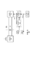
- FIG. 1 illustrates an isolated measurement system 100 according to an embodiment of the present invention.
- the system 100 may define an isolation barrier 110 that establishes two galvanically isolated voltage domains 120, 130.
- Each voltage domain 120, 130 may have voltage supplies and ground references that are isolated from each other.
- the system 100 also may include various isolator devices 140, 150 to exchange power and data between the voltage domains 120, 130 while still maintaining galvanic isolation between them.
- the first voltage domain 120 may include a control system 160 to manage operations of the system 100 and, therefore, it is called a "control system domain” herein.
- the second voltage domain 130 may include a measurement system 170 and, therefore, it is called a "measurement system domain" herein.
- the control system 160 and measurement system 170 may exchange communication with each other via communication isolators 150.
- the communication may include exchange of control signals, timing signals and/or data.
- the communication isolators 150 may be implemented as capacitors, transformers and/or opto-electric devices.
- a single bidirectional communication isolator 150 is shown in FIG. 1 but the system may include other communication isolators 150, which may be unidirectional and/or bidirectional, to provide higher bandwidth communication between the voltage domains 120, 130 as may be appropriate for individual application needs.
- the control system domain 120 may include a power transmitter 180 and the measurement system domain 130 may include a power receiver 190.
- the power transmitter 180 may have outputs connected to an input side of a power isolator 140 and the power receiver 190 may have inputs connected to an output side of the same power isolator 140.
- the power isolator 140 may be implemented as capacitors, transformers and/or optoelectronic devices.
- the power transmitter 180 may generate an oscillating output signal (ISO PWR) to the power isolator 140 in response to a control signal PWR CTRL .
- the power transmitter 180 may include an inductor-capacitor oscillator (not shown), which may set an operating frequency of the oscillating output signal ISO PWR.
- the PWR CTRL signal may gate operation of the power transmitter 180 which may selectively enable it to generate the output signal to the power isolator 140 or disable it from doing so. Disabling the power transmitter 180 reduces an amount of electromagnetic interference that the power transmitter 180 may inject into operation of other circuit systems, for example, the measurement system 170 of the measurement system domain 130.
- FIG. 1 illustrates components of an exemplary measurement system 170, which may include a controller 172, a communication unit 174 and measurement circuit(s) 176.
- the controller 172 may manage operation of the measurement system 170 and may generate timing references for other components of the measurement system 170.
- the communication unit 174 may exchange bidirectional communication signals with the control system 160 of the control system domain 120 across communication isolator 150.
- the measurement circuit 176 represents circuitry to measure various external signals input to the system 100 for a test subject (not shown).
- Operations of the measurement circuit 176 may be high-precision operations that can be corrupted by interference generated by electrical activity of other components within the measurement system 100, including the power transmitter 180 and the power receiver 190.
- the measurement circuit 176 may perform its operations according to a measurement clock signal CLK MEAS provided by the controller 172.
- the measurement circuit 176 may include one or more analog-to-digital converters ("ADCs") (not shown) to digitize externally provided voltages, each of which may be single or multi-bit ADCs (not shown).
- the measurement circuit 176 may include one or more sigma-delta (" ⁇ ") ADCs or multi-bit ADCs.
- the measurement circuit 176 may include one or more capacitive sample-and-hold circuits (not shown) or other similarly situated sampling components to sample the external voltage prior to digitization.
- FIG. 1 also illustrates components of an exemplary control system 160, which may include a controller 162, a communication unit 164, a power controller 166 and, optionally, an input/output ("I/O") unit 168.
- the controller 162 may manage operation of the control system 160 and may generate timing references for components within the control system 160.
- the communication unit 164 may exchange bidirectional communication signals with its counterpart communication unit 174 in the measurement system 170 via the communication isolator 150.
- the power controller 166 may gate operation of the power transmitter 180.
- the I/O unit 168 may interface with processors and/or controllers external to the system 100 (not shown) which may enable transmission of data from the measurement system 100 and/or reception of command(s) for management of the measurement system 100.
- the control system 160 may generate timing signals to govern operation of the power transmitter 180 and the measurement system 170.
- the controller 162 may generate a master clock signal CLK MSTR from which other timing signals are derived.
- CLK MSTR signal may be communicated to the measurement system 170 via the communication units 164, 174 and a communication isolator 150, which may serve as a basis for derivation of the measurement clock signal CLK MEAS .
- the controller 162 also may output the master clock signal CLK MSTR to the power controller 166, which may derive a power transmitter control signal PWR CTRL therefrom.
- the power transmitter control signal PWR CTRL may be output to the power transmitter 180 to gate its operation, selectively enabling it and disabling it at times during which high-precision events will occur in the measurement system 170.
- FIG. 2 is a timing diagram 200 illustrating operation of a control system according to an embodiment of the present invention.
- FIG. 2 illustrates relationships among a master clock signal CLK MSTR , a measurement clock signal CLK MEAS , a power transmitter control signal PWR CTRL and a power isolator signal ISO PWR.
- the master clock signal CLK MSTR may be generated by a controller 162 within the control system domain 120 ( FIG. 1 ).
- the clock measurement signal CLK MEAS may be derived within the measurement system domain 130 from the master clock signal CLK MSTR .
- the power transmitter control signal PWR CTRL may be generated by the power controller 166 to the power transmitter 180 and may control timing of the power isolator signal ISO PWR.
- the master clock signal CLK MSTR may be communicated to the measurement system 170 by the communication units 164, 174 and the isolator 150.
- the controller 172 within the measurement system domain 130 may derive the measurement clock signal CLK MEAS from the communicated CLK MSTR signal.
- Edges 202-208 within the master clock signal CLK MSTR may be replicated as corresponding edges 210-214 of the measurement clock signal CLK MEAS with a delay t delay imposed by the communication and derivation operations performed by intermediate circuitry 150, 164, 174.
- the communication unit 174 may convert edges of the CLK MSTR signal to pulses or other transmission signals that are appropriate for transmission via a communication isolator 150 and the communication unit 164 and controller 172 may generate a recovered clock signal CLK MEAS from the signals received from the communication isolator 510.
- the measurement system 170 may perform data capture operations on rising and/or falling edges 210-214 of the measurement clock signal CLK MEAS , which may occur at some time after corresponding edges 202-208 of the CLK MSTR signal.
- the exact amount of delay t delay among the edges may vary over time due to process, voltage and/or temperature variations of the system 100. Therefore, the control system 160 within the control system domain 120 may not have information to estimate a precise time of delay between edges 202-208 and 210-214 of the CLK MSTR and CLK MEAS signals, respectively.
- the power controller 166 may derive a PWR CTRL signal from the CLK MSTR signal.
- the PWR CTRL signal may include activation pulses 218-224 that are timed so as not to coincide with critical edges 202-208 within the CLK MSTR signal.
- the power transmitter 160 may generate power delivery signals 226-232 in response to activation pulses 218-224 in the PWR CTRL signal.
- the PWR CTRL signal is illustrated as an active high signal; thus, the power transmitter 180 may generate its power delivery signals ISO PWR during times when the PWR CTRL signal is set at a high level.
- the activation pulses 218-224 may be timed so as not to coincide with critical edges 210-216 within the CLK MEAS signal.
- the activation pulses 218-224 may be defined to have terminating edges 234-240 that end a predetermined time before corresponding next edges 202-208 of the CLK MSTR signal. Terminating edges 234-240 may cause suspension of power delivery signals 226-232, which may reduce corruption that may be generated by the power transmitter 180, power isolator 140 and power receiver 190.
- the PWR CTRL signal may remain disabled for some time after the transition of the next edge 202, 204 of the CLK MSTR signal, whereupon a next activation pulse may initiate.
- the suspension of the activation pulses 218-224 may induce windows of "quiet time" (shown as t quiet ) in operation of the power transmitter 180, power isolator 140 and power receiver 190 provided about the edges in the master clock signal CLK MSTR .
- the quiet time may reduce corruption within the system 100 by suspending operation of the power transmitter 180.
- the quiet time may be defined to include transitions 210-216 in the CLK MEAS signal based on expectations of delay induced by the communication units 164, 175 and the communication isolator 150. Transitions 210-216 in the CLK MEAS signal may trigger data capture operations within the system 100 and, therefore, reduced interference is expected to contribute to accuracy of such data capture operations.
- FIG. 2 illustrates some of the timing variations that may be used in accordance with an embodiment of the present invention.
- activation pulses 218-224 are illustrated as centered within each half cycle of the master clock CLK MSTR , other implementations are permissible.
- pulse 218 is illustrated as aligned with an onset of the quiet window surrounding edge 202 in the master clock signal CLK MSTR .
- an activation pulse may be aligned with the conclusion of such quiet windows.
- it is permissible for activation pulses to fit the entire period between such windows it may prove useful to provide activation pulses that are much smaller than the time period between such windows to provide power control in such systems 100.
- the master clock signal CLK MSTR and the measurement clock signal CLK MEAS are illustrated as 50% duty cycle clocks having even distribution between rising and falling edges.
- Such clock signals often are used in a system that performs data capture on rising and falling edges of a sampling clock (in this case, CLK MEAS ).
- CLK MEAS sampling clock
- the principles of the present invention may be extended to other types of clocks, for example, pulsed clocks having uneven distributions between rising and falling edges and to other types of systems, for example, systems that perform data capture on only one type of edge (e.g., a rising or a falling edge of a sampling clock).
- Such operational variations are immaterial to the principles of the present invention except where noted herein.
- some systems may not use all edges of a CLK MSTR signal or, by extension, all edges of a CLK MEAS signal to perform data capture operations.
- it may not be necessary to introduce quiet times to the power transmitter's output ISO PWR for all edges of the master clock signal CLK MSTR . Rather, it may be sufficient to introduce such quiet times only for those edges that will be used for data capture operations in a measurement system 170.
- the measurement system 170 and control system 160 may engage in a predetermined communication protocol across the communication isolator 150.
- the control system's master clock signal CLK MSTR may define timing of measurement operations to be performed by the measurement system 170 by defining the CLK MEAS signal.
- the control system 160 also may include commands or other data to be provided in conjunction with the master clock signal CLK MSTR that are communicated to the measurement system 170 via the communication isolator 150.
- the measurement system 170 may report data representing its measurements to the control system 160.
- communication of data across the communication isolator 150 may be performed synchronously with respect to the master clock signal CLK MSTR .
- the measurement system 170 may include a supply monitor 178 to measure output from the power receiver 190.
- the supply monitor 178 may provide power measurement data to the controller 172, which may communicate it to the control system 160 via the communication units 164, 174 and a communication isolator 150.
- the power measurement data may be merged with measurement data from the measurement circuit 176 as it is communicated to the control system 160.
- the supply monitor 178 may generate data for the control system 160, which may include power control information to manage operation of the power transmitter 180.
- the supply monitor 178 may include a resistor divider network and a comparator (not shown), as described in more detail below.
- the power control information may indicate whether the power transmitter 180 should supply more or less power to the measurement system domain 130.
- the power control information from the supply monitor 178 may be represented by a single bit flag that is generated at periodic intervals, wherein a logic level '0' may indicate that the measurement system 170 needs less power, and a logic level '1' may indicate that the measurement system 170 needs more power.
- the controller 162 may parse the power measurement data and any other measurement data from communications received by the communication unit 164 and may relay the power measurement data to the power controller 166.
- the power measurement data may be a single bit signal indicating a need for more power or less power.
- the power controller 166 may modulate the PWR CTRL signal according to power measurement data received from the measurement system 170.
- the power controller 166 may be configured to interpret an excess number of "less power” indicators to be generated as a system error, and, in turn, may control the power transmitter 180 to generate a minimum power level to ensure proper operation of the measurement system 170. Conversely, the power controller 166 may be configured to interpret repeated power feedback information indicating "more power" to be generated as another system error, and, in turn may control the power transmitter to generate a maximum power level for the measurement system 170. In an embodiment, the minimum and maximum power levels may be configured during manufacture of the isolated measurement system 100.
- Embodiments of the present invention also may increase power generation reliability by providing for power generation states, which may provide a minimum power level needed to operate the measurement system 170 and a maximum power level, which the measurement system 170 may consume without damaging the system 100.
- power generation states may provide a minimum power level needed to operate the measurement system 170 and a maximum power level, which the measurement system 170 may consume without damaging the system 100.
- the power regulation feedback information may be at a low logic level (e.g., which, during normal operation may indicate that the measurement system may need less power) because the supply monitor 178 is not yet powered.
- the power receiver 190 may include a full-wave rectifier (not shown) and a filtering capacitor C to generate the supply voltage V SUPP for the measurement system domain 120.
- the power receiver 190 may generate a supply voltage V SUPP that varies based on the operating frequency and operational duty rate of the power transmitter 180.
- the filtering capacitor C may be provided as a discrete component that is external to an integrated circuit in which the power receiver 190 is fabricated.
- the power receiver 190 therefore, may provide for storage of power supplied by the power transmitter 180 and may maintain the power stable for periods of time even when the power transmitter 180 is disabled.
- the power isolator 140 may be provided as a transformer-based, capacitor-based or optical-based isolator. Isolated power generation and isolators are described in U.S. Pat. No. 8,089,311 and U.S. Pat. No. 7,075,329 , the contents of which are incorporated herein.
- FIG. 3 is a functional block diagram of a control system 300 according to an embodiment of the present invention.
- the control system 300 may generate a clock control signal PWR CTRL to a power transmitter 310, which in turn may drive signals to a power isolator 320 and to a power receiver 330.
- the control system 300 may include a power controller 340 and a clock generator 350.
- the power controller 340 may generate the PWR CTRL signal to the power transmitter 310 in response to a master clock signal CLK MSTR .
- the clock generator 350 may generate the master clock signal CLK MSTR to the power controller 340.
- the power controller 340 may include a signal generator 342 that generates the PWR CTRL signal.
- the signal generator 342 may generate a pulsed signal that defines periods of activity and inactivity of the power transmitter 310.
- the periods of inactivity may coincide with portions of the master clock signal CLK MSTR that define high precision operations within the system 300.
- the power controller 340 may include a feedback controller 344 that interprets power control signals received from other circuit systems and provides feedback signals to the signal generator 342.
- the feedback controller 344 may interpret power control signals received from other system sources (such as the measurement system domain 130 of FIG. 1 ) and determine whether such feedback signals indicate requests for increased or decreased power.
- the feedback controller 334 may provide data to the signal generator 342.
- the signal generator 342 may modulate the PWR CTRL signal output to the power transmitter 310 to accommodate requests included in the power control signals.
- the PWR CTRL signal may toggle between a predetermined number of pulse widths (shown as t max and t min in FIG. 2 ).
- the power transmitter 310 may generate active output signals ISO PWR during times when the PWR CTRL is in an active state.
- the PWR CTRL signal may be a pulse-width modulated signal (not shown in FIG. 2 ) whose pulse width may vary within a predetermined range as determined by the power control signals. Again, the duty cycle of the power transmitter's 180 output and, therefore, an amount of power delivered to the measurement system domain 130 ( FIG. 1 ).
- the power controller 340 may respond to power control signals that indicate a need to provide more or less power but may include functionality to determine whether an excess number of "more power” or “less power” indicators have been received.
- the feedback controller 344 may include an accumulator (not shown) to maintain running counts of the more power or less power indicators that have been received within a predetermined period of time. The feedback controller 344 may compare the counts to predetermined thresholds representing excess numbers of "more power” or "less power” indications.
- the feedback controller 344 may override output signals that otherwise would be provided by the accumulator and, instead, provide a feedback signal to the signal generator 342 that maintains the power transmitter 310 in a nominal operating range.
- Embodiments of the present invention also may increase power generation reliability by providing for power generation states, which may provide a minimum power level needed to operate the measurement system 170 and a maximum power level, which the measurement system 170 may consume without damaging the system 100.
- the power regulation feedback information may be at a low logic level (e.g., which, during normal operation may indicate that the measurement system 170 may need less power) because the supply monitor 178 is not yet powered.
- the feedback controller 344 may ignore power control commands that indicate the measurement system domain 130 needs less power.
- the system may provide a "minimum life support" power, in which an empirically determined minimum power may be sent to the measurement system domain 130.
- the empirically determined minimum power may be determined by experiments that may ensure the measurement system domain 130 may receive a minimum amount of power but will be functional (e.g., to generate power regulation feedback information and to send back to the non-isolated side).
- the feedback controller 334 may monitor occurrences of such power control data and limit delivery of power to "maximum life support" power level.
- the feedback controller 334 may limit the power transmitter 180 ( FIG. 1 ) to prevent providing too much power to the measurement system domain 130.
- the maximum power may also be determined by experiments that may ensure the measurement system domain 130 receives a maximum amount of power but will not be damaged.
- the clock generator 350 may generate the master clock signal CLK MSTR .
- the master clock signal may be generated internally within the clock generator 350.
- the clock generator 350 may include a ring oscillator or other self-contained clock generator circuit.
- the master clock signal CLK MSTR may be derived from an externally-provided clock signal (not shown in FIG. 3 ), in which case the clock generator 350 may be provided as a phase lock loop, a delay lock loop or other appropriate clock generator.
- the clock generator 350 may output the CLK MSTR signal to the power controller 340 and other circuit systems without alteration.
- FIG. 4 contains simplified block diagrams of various supply monitors 400 according to an embodiment of the present invention.
- the supply monitor 400 may find application in the measurement system 170 of FIG. 1 .
- the supply monitor 400 may include a voltage divider 410 and a comparator 420.
- the voltage divider 410 may have an input coupled to the V SUPP voltage supply. It may divide the input voltage V SUPP by a scaling factor and output a voltage V DIV , representing the divided-down voltage.
- the voltage divider 410 may be provided as a resistor divider ( FIG. 4(b) ).
- the V DIV voltage may be input to a first input terminal of the comparator 420.
- a reference voltage V REF may be input to a second input terminal of the comparator 420.
- the reference voltage V REF may be a bandgap reference voltage locally generated at the measurement system 170.
- the comparator 420 may generate a binary output signal representing a comparison between the V DIV voltage and the V REF voltage. The comparator's output may become a power control signal within the measurement system 170 of FIG. 1 .
- the supply monitor 400 may provide a multi-bit output that indicates three states: power should be increased, power should be decreased and power should remain unchanged.
- the voltage divider 410' may output a pair of voltages, a high threshold V DIVHI and a low threshold V DIVLO , that may be output to respective comparators 420.1, 420.2.
- the comparators 420.1, 420.2 also may receive the V REF voltage on other inputs, which again may be a bandgap reference voltage. If the V DIVHI voltage exceeds the V REF voltage, the comparator 420.1 may generate an output that indicates a power decrease is warranted. If the V DIVLO voltage is lower than the V REF voltage, the comparator 420.2 may generate an output that indicates a power increase is warranted. If neither comparator 420.1 nor 420.2 generates such outputs, it may indicate no power changed is warranted.
- FIG. 5 illustrates a system for communicating timing information and power control data within a system 500 according to another embodiment of the present invention.
- the system 500 may include a control system 510 and a measurement system 520 separated by an isolation barrier 530.
- the system 500 may include a pair of unidirectional isolators 540.1, 540.2 to communicate the timing and power control signals between the control system 510 and the measurement system 520.
- the system 500 may communicate timing and data from the control system 510 to the measurement system 520 via a first isolator 540.1.
- the system 500 may communicate power control signals and data from the measurement system 520 to the control system 510 via the second isolator 540.2.
- control system 510 may include a controller 512, a communication unit 514, a power controller 516 and an I/O unit 518.
- the communication unit 514 is illustrated as having a transmitter 514A coupled to the first isolator 540.1 and a receiver 514B coupled to the second isolator 540.2.
- the power controller 516 and I/O unit 518 may operate as in the foregoing embodiments.
- the measurement system 520 may include a controller 522, a communication unit 524, a supply monitor 526 and measurement circuit(s) 528.
- the communication unit 524 is illustrated as having a transmitter 524A coupled to the second isolator 540.2 and a receiver 524B coupled to the second isolator 540.1.
- the supply monitor 526 and measurement circuit(s) 528 may operate as in the foregoing embodiments.
- the controller 512 may generate timing signals corresponding to CLK MSTR events and may output the signals to the transmitter 514A.
- the transmitter 514A may modulate an isolator transmission signal representing the CLK MSTR signal.
- the controller 512 may multiplex the CLK MSTR events with other control data and output a multiplexed signal to the transmitter 514A.
- the transmitter 514A may modulate the isolator transmission signal representing the multiplexed signal and drive the isolator 540.1 according to the isolator transmission signal.
- the receiver 524B may receive the isolator transmission signals from the first isolator 540.1 and may recover data therefrom.
- the receiver 524B may output the recovered data to the controller 522.
- the controller 522 may generate a timing reference for the measurement circuit(s) 528 from timing information present in the recovered data. If the recovered data includes additional control data, the controller 522 may interpret such data and configure its operation in response to it.
- the controller 522 within the measurement system domain may receive power control data from the supply monitor 526.
- the controller 522 also may receive measurement data from the measurement circuits 528.
- the controller 522 may multiplex the power control data with the measurement data and provide the multiplexed data to a transmitter 524A within the communication unit 524.
- the transmitter 524A may modulate an isolator transmission signal according to the data provided by the controller 522 and may drive the second isolator 540.2 accordingly.
- the receiver 514B may receive the isolator transmission signal from the second isolator 540.2 and may recover data therefrom.
- the receiver 514B may output the recovered data to the controller 512.
- the controller 512 may parse the recovered data into power control signals and measurement data.
- the controller 512 may provide the power control signal to the power controller 516 and may provide measurement data to the I/O unit 518.
- FIG. 6 illustrates a power generation system 600 according to another embodiment of the present invention.
- FIG. 6 illustrates the power generation system 600 provided in a system-in-package ("SIP") configuration.
- the power transmitter 610, power receiver 620 and power isolator 630 may be provided as separate components.
- the power transmitter 610 and power receiver 620 may be provided on separate semiconductor dies, which may be mounted on a package substrate 640 such as a non-conductive carrier ( FIG. 6(a) ) or a conductive split carrier ( FIG. 6(b) ).
- the power isolator 630 may be provided on the package substrate 640 or, alternatively, may be provided on a separate substrate that may be mounted on the package substrate 640. In the embodiment illustrated in FIG.
- the power isolator 630 is illustrated as a micro-transformer formed of a pair of spiral conductors (not shown separately) that overlap each other on the substrate 640 and are separated by a dielectric.
- a first spiral conductor may be coupled to the power transmitter 610 by bridging conductors and a second spiral conductor may be coupled to the power receiver 620 also by bridging conductors.
- the power isolator 630 may be formed as a capacitor network, in which case the power transmitter 610 and power receiver 620 would be coupled to respective capacitor plates by bridging conductors.
- FIG. 6 also illustrates the control system 650, the measurement system 660 and the communication isolator(s) 670 provided as separate components.
- the control system 650 and measurement system 660 may be provided on separate semiconductor dies, which may be mounted on the package substrate 640.
- the communication isolator(s) 670 may be provided on the package substrate 640 or, alternatively, may be provided on a separate substrate that may be mounted on the package substrate 640.
- the communication isolators 670 are illustrated as a pair of micro-transformers each formed of a pair of spiral conductors (not shown separately) that overlap each other on the substrate 640 and are separated by a dielectric.
- a first spiral conductor may be coupled to the control system 650 by bridging conductors and a second spiral conductor may be coupled to the measurement system 660 also by bridging conductors.
- the communication isolator(s) 670 also may be formed as capacitive or as optical couplers.
- the power transmitter 610 and power receiver 620 would be coupled to a respective capacitor plate by bridging conductors.
- transmitters within the control system 650 and the measurement system 660 may be coupled to respective optical transmitters within the optical coupler and receivers within the control system 650 and the measurement system 660 may be coupled to respective optical receivers.
- FIG. 6 illustrates an exemplary set of package pins P coupled to respectively components of the system 600.
- a pair of pins may be provided to couple the power receiver 620 to a discrete capacitor.
- Other pins may be provided for I/O communication and an external clock CLK, which may be coupled to the control system 650.
- Still other sets of pins may be provided for coupling test subjects to the measurement system 660.
- two pairs of pins are provided for two test subjects (represented as "measurement channels" of the system 600).
- the package also may have pins for connection to supply voltages, for example, V DD and ground supplies for the control system 650 and power transmitter 610.
- the power transmitter 610 and control system 650 may be provided in a first package and the power receiver 620 and the measurement system 660 may be provided in a second package.
- the isolators 630, 670 may be provided in their own, third package or, alternatively, may be provided in one of the first or second packages.
Abstract
Description
- The present invention benefits from priority afforded by
U.S. patent application serial no. 61/636,797 - An isolated measurement system typically includes a measurement system to measure external signals and a control system to control the measurement system and receive measurement data therefrom. The two systems operate in two different voltage domains that are galvanically isolated from each other. The measurement system often includes multiple channels, each with its own measurement system and converter. Each channel transmits sampled data, in an asynchronous manner, to the control system through a respective data communication transformer.
- A power generator provided in a voltage domain of the control system generates power for a voltage domain of the measurement system. The power generator includes a power transmitter in the control system's domain coupled to a rectifier in the measurement system's domain via a transformer that bridges an isolation barrier between the two domains. The power transmitter and rectifier are active continuously to ensure power supply to the measurement system is continuous. A power monitor may measure a voltage supply provided by the rectifier and may generate power feedback data therefrom, which is communicated to the control system's domain via a dedicated isolation transformer.
- Modern applications of isolated measurement systems call for sampling and conversion operations to be performed with increasing precision. The inventors have determined that the operations of the power transmitter and/or rectifier can inject undesired electromagnetic interference into the operation of such systems. Accordingly, the inventors have identified a need for an isolated measurement system in which a powered control system may deliver power to an otherwise unpowered measurement system and yet reduce electromagnetic interference that the power delivery might inject into operations of the measurement system. The inventors also have identified a need for such a system in which communication of power feedback data makes efficient use of isolators.
-
FIG. 1 illustrates a power generation system according to an embodiment of the present invention. -
FIG. 2 illustrates a system for managing power generation according to an embodiment of the present invention. -
FIG. 3 is a signal diagram illustrating exemplary control signals according to an embodiment of the present invention. -
FIG. 4 illustrates supply monitors according to various embodiments of the present invention. -
FIG. 5 illustrates a system for communicating timing information and power control data according to another embodiment of the present invention. -
FIG. 6(a) illustrates a power generation system provided in a system-in-package configuration on a non-conductive carrier package substrate according to an embodiment of the present invention. -
FIG. 6(b) illustrates a power generation system provided in a system-in-package configuration on a conductive split carrier package substrate according to an embodiment of the present invention. - Embodiments of the present invention provide a power delivery system for an isolated measurement system in which a power transmitter and power receiver are provided at powered and unpowered sides of an isolation barrier respectively. The power transmitter and power receiver may be coupled by a common isolator. The power transmitter may deliver power to the power receiver to power components on the unpowered side of the isolation barrier. The system may include a controller provided in the powered side to generate a clock signal defining timing of a predetermined operation of the measurement system and to generate a disabling signal to the power transmitter controller coincident with the timing of the predetermined operation.
- In another embodiment, the system may include a supply monitor on the unpowered side of the isolation barrier to determine whether power supplied by the power receiver is within operating tolerances. The supply monitor may generate power control commands that may be multiplexed with data from other systems on the unpowered domain and communicated to the controller on the powered domain. The controller may alter power delivery by the power transmitter in response to the power control commands.
-
FIG. 1 illustrates anisolated measurement system 100 according to an embodiment of the present invention. Thesystem 100 may define anisolation barrier 110 that establishes two galvanicallyisolated voltage domains voltage domain system 100 also may includevarious isolator devices 140, 150 to exchange power and data between thevoltage domains system 100 illustrated inFIG. 1 , thefirst voltage domain 120 may include acontrol system 160 to manage operations of thesystem 100 and, therefore, it is called a "control system domain" herein. Thesecond voltage domain 130 may include ameasurement system 170 and, therefore, it is called a "measurement system domain" herein. - The
control system 160 andmeasurement system 170 may exchange communication with each other via communication isolators 150. The communication may include exchange of control signals, timing signals and/or data. The communication isolators 150 may be implemented as capacitors, transformers and/or opto-electric devices. A single bidirectional communication isolator 150 is shown inFIG. 1 but the system may include other communication isolators 150, which may be unidirectional and/or bidirectional, to provide higher bandwidth communication between thevoltage domains - The
control system domain 120 may include apower transmitter 180 and themeasurement system domain 130 may include apower receiver 190. Thepower transmitter 180 may have outputs connected to an input side of apower isolator 140 and thepower receiver 190 may have inputs connected to an output side of thesame power isolator 140. Thepower isolator 140 may be implemented as capacitors, transformers and/or optoelectronic devices. - The
power transmitter 180 may generate an oscillating output signal (ISO PWR) to thepower isolator 140 in response to a control signal PWRCTRL. In an embodiment, thepower transmitter 180 may include an inductor-capacitor oscillator (not shown), which may set an operating frequency of the oscillating output signal ISO PWR. During operation, the PWRCTRL signal may gate operation of thepower transmitter 180 which may selectively enable it to generate the output signal to thepower isolator 140 or disable it from doing so. Disabling thepower transmitter 180 reduces an amount of electromagnetic interference that thepower transmitter 180 may inject into operation of other circuit systems, for example, themeasurement system 170 of themeasurement system domain 130. -
FIG. 1 illustrates components of anexemplary measurement system 170, which may include acontroller 172, acommunication unit 174 and measurement circuit(s) 176. Thecontroller 172 may manage operation of themeasurement system 170 and may generate timing references for other components of themeasurement system 170. Thecommunication unit 174 may exchange bidirectional communication signals with thecontrol system 160 of thecontrol system domain 120 across communication isolator 150. Themeasurement circuit 176 represents circuitry to measure various external signals input to thesystem 100 for a test subject (not shown). - Operations of the
measurement circuit 176, such as sampling of the external signals, may be high-precision operations that can be corrupted by interference generated by electrical activity of other components within themeasurement system 100, including thepower transmitter 180 and thepower receiver 190. Themeasurement circuit 176 may perform its operations according to a measurement clock signal CLKMEAS provided by thecontroller 172. By way of example, themeasurement circuit 176 may include one or more analog-to-digital converters ("ADCs") (not shown) to digitize externally provided voltages, each of which may be single or multi-bit ADCs (not shown). In another embodiment, themeasurement circuit 176 may include one or more sigma-delta ("ΣΔ") ADCs or multi-bit ADCs. In another embodiment, themeasurement circuit 176 may include one or more capacitive sample-and-hold circuits (not shown) or other similarly situated sampling components to sample the external voltage prior to digitization. -
FIG. 1 also illustrates components of anexemplary control system 160, which may include acontroller 162, acommunication unit 164, apower controller 166 and, optionally, an input/output ("I/O")unit 168. Thecontroller 162 may manage operation of thecontrol system 160 and may generate timing references for components within thecontrol system 160. Thecommunication unit 164 may exchange bidirectional communication signals with itscounterpart communication unit 174 in themeasurement system 170 via the communication isolator 150. Thepower controller 166 may gate operation of thepower transmitter 180. The I/O unit 168 may interface with processors and/or controllers external to the system 100 (not shown) which may enable transmission of data from themeasurement system 100 and/or reception of command(s) for management of themeasurement system 100. - Within the
control system domain 120, thecontrol system 160 may generate timing signals to govern operation of thepower transmitter 180 and themeasurement system 170. Thecontroller 162 may generate a master clock signal CLKMSTR from which other timing signals are derived. For example, the CLKMSTR signal may be communicated to themeasurement system 170 via thecommunication units controller 162 also may output the master clock signal CLKMSTR to thepower controller 166, which may derive a power transmitter control signal PWRCTRL therefrom. The power transmitter control signal PWRCTRL may be output to thepower transmitter 180 to gate its operation, selectively enabling it and disabling it at times during which high-precision events will occur in themeasurement system 170. -
FIG. 2 is a timing diagram 200 illustrating operation of a control system according to an embodiment of the present invention.FIG. 2 illustrates relationships among a master clock signal CLKMSTR, a measurement clock signal CLKMEAS, a power transmitter control signal PWRCTRL and a power isolator signal ISO PWR. The master clock signal CLKMSTR may be generated by acontroller 162 within the control system domain 120 (FIG. 1 ). The clock measurement signal CLKMEAS may be derived within themeasurement system domain 130 from the master clock signal CLKMSTR. The power transmitter control signal PWRCTRL may be generated by thepower controller 166 to thepower transmitter 180 and may control timing of the power isolator signal ISO PWR. - The master clock signal CLKMSTR may be communicated to the
measurement system 170 by thecommunication units controller 172 within themeasurement system domain 130 may derive the measurement clock signal CLKMEAS from the communicated CLKMSTR signal. Edges 202-208 within the master clock signal CLKMSTR may be replicated as corresponding edges 210-214 of the measurement clock signal CLKMEAS with a delay tdelay imposed by the communication and derivation operations performed byintermediate circuitry communication unit 174 may convert edges of the CLKMSTR signal to pulses or other transmission signals that are appropriate for transmission via a communication isolator 150 and thecommunication unit 164 andcontroller 172 may generate a recovered clock signal CLKMEAS from the signals received from thecommunication isolator 510. Themeasurement system 170 may perform data capture operations on rising and/or falling edges 210-214 of the measurement clock signal CLKMEAS, which may occur at some time after corresponding edges 202-208 of the CLKMSTR signal. Moreover, the exact amount of delay tdelay among the edges may vary over time due to process, voltage and/or temperature variations of thesystem 100. Therefore, thecontrol system 160 within thecontrol system domain 120 may not have information to estimate a precise time of delay between edges 202-208 and 210-214 of the CLKMSTR and CLKMEAS signals, respectively. - The
power controller 166 may derive a PWRCTRL signal from the CLKMSTR signal. The PWRCTRL signal may include activation pulses 218-224 that are timed so as not to coincide with critical edges 202-208 within the CLKMSTR signal. Thepower transmitter 160 may generate power delivery signals 226-232 in response to activation pulses 218-224 in the PWRCTRL signal. In the example ofFIG. 2 , the PWRCTRL signal is illustrated as an active high signal; thus, thepower transmitter 180 may generate its power delivery signals ISO PWR during times when the PWRCTRL signal is set at a high level. - As indicated, the activation pulses 218-224 may be timed so as not to coincide with critical edges 210-216 within the CLKMEAS signal. The activation pulses 218-224 may be defined to have terminating edges 234-240 that end a predetermined time before corresponding next edges 202-208 of the CLKMSTR signal. Terminating edges 234-240 may cause suspension of power delivery signals 226-232, which may reduce corruption that may be generated by the
power transmitter 180,power isolator 140 andpower receiver 190. The PWRCTRL signal may remain disabled for some time after the transition of thenext edge - The suspension of the activation pulses 218-224 may induce windows of "quiet time" (shown as tquiet) in operation of the
power transmitter 180,power isolator 140 andpower receiver 190 provided about the edges in the master clock signal CLKMSTR. As indicated, the quiet time may reduce corruption within thesystem 100 by suspending operation of thepower transmitter 180. The quiet time may be defined to include transitions 210-216 in the CLKMEAS signal based on expectations of delay induced by thecommunication units 164, 175 and the communication isolator 150. Transitions 210-216 in the CLKMEAS signal may trigger data capture operations within thesystem 100 and, therefore, reduced interference is expected to contribute to accuracy of such data capture operations. -
FIG. 2 illustrates some of the timing variations that may be used in accordance with an embodiment of the present invention. For example, although activation pulses 218-224 are illustrated as centered within each half cycle of the master clock CLKMSTR, other implementations are permissible. For example,pulse 218 is illustrated as aligned with an onset of the quietwindow surrounding edge 202 in the master clock signal CLKMSTR. Alternatively, an activation pulse may be aligned with the conclusion of such quiet windows. And, while it is permissible for activation pulses to fit the entire period between such windows, it may prove useful to provide activation pulses that are much smaller than the time period between such windows to provide power control insuch systems 100. - In the embodiment illustrated in
FIG. 2 , the master clock signal CLKMSTR and the measurement clock signal CLKMEAS are illustrated as 50% duty cycle clocks having even distribution between rising and falling edges. Such clock signals often are used in a system that performs data capture on rising and falling edges of a sampling clock (in this case, CLKMEAS). The principles of the present invention, however, may be extended to other types of clocks, for example, pulsed clocks having uneven distributions between rising and falling edges and to other types of systems, for example, systems that perform data capture on only one type of edge (e.g., a rising or a falling edge of a sampling clock). Such operational variations are immaterial to the principles of the present invention except where noted herein. - Moreover, some systems may not use all edges of a CLKMSTR signal or, by extension, all edges of a CLKMEAS signal to perform data capture operations. In such applications, it may not be necessary to introduce quiet times to the power transmitter's output ISO PWR for all edges of the master clock signal CLKMSTR. Rather, it may be sufficient to introduce such quiet times only for those edges that will be used for data capture operations in a
measurement system 170. - Returning to
FIG. 1 , themeasurement system 170 andcontrol system 160 may engage in a predetermined communication protocol across the communication isolator 150. The control system's master clock signal CLKMSTR may define timing of measurement operations to be performed by themeasurement system 170 by defining the CLKMEAS signal. Thecontrol system 160 also may include commands or other data to be provided in conjunction with the master clock signal CLKMSTR that are communicated to themeasurement system 170 via the communication isolator 150. Themeasurement system 170 may report data representing its measurements to thecontrol system 160. In an embodiment, communication of data across the communication isolator 150 may be performed synchronously with respect to the master clock signal CLKMSTR. - In another embodiment, the
measurement system 170 may include asupply monitor 178 to measure output from thepower receiver 190. The supply monitor 178 may provide power measurement data to thecontroller 172, which may communicate it to thecontrol system 160 via thecommunication units measurement circuit 176 as it is communicated to thecontrol system 160. By multiplexing power control data with other data, the design eliminates a need for a dedicated isolator to manage power generation, thus the number of isolators 150 for thesystem 100 can be reduced. - The supply monitor 178 may generate data for the
control system 160, which may include power control information to manage operation of thepower transmitter 180. In an embodiment, thesupply monitor 178 may include a resistor divider network and a comparator (not shown), as described in more detail below. The power control information may indicate whether thepower transmitter 180 should supply more or less power to themeasurement system domain 130. For example, the power control information from thesupply monitor 178 may be represented by a single bit flag that is generated at periodic intervals, wherein a logic level '0' may indicate that themeasurement system 170 needs less power, and a logic level '1' may indicate that themeasurement system 170 needs more power. - The
controller 162 may parse the power measurement data and any other measurement data from communications received by thecommunication unit 164 and may relay the power measurement data to thepower controller 166. In an embodiment, the power measurement data may be a single bit signal indicating a need for more power or less power. Thepower controller 166 may modulate the PWRCTRL signal according to power measurement data received from themeasurement system 170. - According to embodiments of the present invention, the
power controller 166 may be configured to interpret an excess number of "less power" indicators to be generated as a system error, and, in turn, may control thepower transmitter 180 to generate a minimum power level to ensure proper operation of themeasurement system 170. Conversely, thepower controller 166 may be configured to interpret repeated power feedback information indicating "more power" to be generated as another system error, and, in turn may control the power transmitter to generate a maximum power level for themeasurement system 170. In an embodiment, the minimum and maximum power levels may be configured during manufacture of theisolated measurement system 100. - Embodiments of the present invention also may increase power generation reliability by providing for power generation states, which may provide a minimum power level needed to operate the
measurement system 170 and a maximum power level, which themeasurement system 170 may consume without damaging thesystem 100. For example, during start-up conditions when no power may be provided to themeasurement system 170, the power regulation feedback information may be at a low logic level (e.g., which, during normal operation may indicate that the measurement system may need less power) because thesupply monitor 178 is not yet powered. - In an embodiment, the
power receiver 190 may include a full-wave rectifier (not shown) and a filtering capacitor C to generate the supply voltage VSUPP for themeasurement system domain 120. Thus, thepower receiver 190 may generate a supply voltage VSUPP that varies based on the operating frequency and operational duty rate of thepower transmitter 180. In an embodiment, the filtering capacitor C may be provided as a discrete component that is external to an integrated circuit in which thepower receiver 190 is fabricated. Thepower receiver 190, therefore, may provide for storage of power supplied by thepower transmitter 180 and may maintain the power stable for periods of time even when thepower transmitter 180 is disabled. For purposes of power transfer, thepower isolator 140 may be provided as a transformer-based, capacitor-based or optical-based isolator. Isolated power generation and isolators are described inU.S. Pat. No. 8,089,311 andU.S. Pat. No. 7,075,329 , the contents of which are incorporated herein. -
FIG. 3 is a functional block diagram of acontrol system 300 according to an embodiment of the present invention. Thecontrol system 300 may generate a clock control signal PWRCTRL to apower transmitter 310, which in turn may drive signals to apower isolator 320 and to apower receiver 330. Thecontrol system 300 may include apower controller 340 and aclock generator 350. Thepower controller 340 may generate the PWRCTRL signal to thepower transmitter 310 in response to a master clock signal CLKMSTR. Theclock generator 350 may generate the master clock signal CLKMSTR to thepower controller 340. - The
power controller 340 may include asignal generator 342 that generates the PWRCTRL signal. In a simple embodiment, thesignal generator 342 may generate a pulsed signal that defines periods of activity and inactivity of thepower transmitter 310. The periods of inactivity may coincide with portions of the master clock signal CLKMSTR that define high precision operations within thesystem 300. - In other embodiments, the
power controller 340 may include afeedback controller 344 that interprets power control signals received from other circuit systems and provides feedback signals to thesignal generator 342. For example, thefeedback controller 344 may interpret power control signals received from other system sources (such as themeasurement system domain 130 ofFIG. 1 ) and determine whether such feedback signals indicate requests for increased or decreased power. The feedback controller 334 may provide data to thesignal generator 342. In response, thesignal generator 342 may modulate the PWRCTRL signal output to thepower transmitter 310 to accommodate requests included in the power control signals. For example, the PWRCTRL signal may toggle between a predetermined number of pulse widths (shown as tmax and tmin inFIG. 2 ). Again, thepower transmitter 310 may generate active output signals ISO PWR during times when the PWRCTRL is in an active state. Alternatively, the PWRCTRL signal may be a pulse-width modulated signal (not shown inFIG. 2 ) whose pulse width may vary within a predetermined range as determined by the power control signals. Again, the duty cycle of the power transmitter's 180 output and, therefore, an amount of power delivered to the measurement system domain 130 (FIG. 1 ). - As indicated, the
power controller 340 may respond to power control signals that indicate a need to provide more or less power but may include functionality to determine whether an excess number of "more power" or "less power" indicators have been received. For example, thefeedback controller 344 may include an accumulator (not shown) to maintain running counts of the more power or less power indicators that have been received within a predetermined period of time. Thefeedback controller 344 may compare the counts to predetermined thresholds representing excess numbers of "more power" or "less power" indications. If the counts were to indicate that excess "more power" or "less power" indications, thefeedback controller 344 may override output signals that otherwise would be provided by the accumulator and, instead, provide a feedback signal to thesignal generator 342 that maintains thepower transmitter 310 in a nominal operating range. - Embodiments of the present invention also may increase power generation reliability by providing for power generation states, which may provide a minimum power level needed to operate the
measurement system 170 and a maximum power level, which themeasurement system 170 may consume without damaging thesystem 100. For example, during start-up conditions when no power may be provided to themeasurement system 170, the power regulation feedback information may be at a low logic level (e.g., which, during normal operation may indicate that themeasurement system 170 may need less power) because thesupply monitor 178 is not yet powered. For example, during start up when the measurement system domain 130 (FIG. 1 ) has not yet been fully powered up, thefeedback controller 344 may ignore power control commands that indicate themeasurement system domain 130 needs less power. In this scenario, the system may provide a "minimum life support" power, in which an empirically determined minimum power may be sent to themeasurement system domain 130. The empirically determined minimum power may be determined by experiments that may ensure themeasurement system domain 130 may receive a minimum amount of power but will be functional (e.g., to generate power regulation feedback information and to send back to the non-isolated side). - In another example, if the
measurement system domain 130 has been running at steady state conditions, and repeatedly indicates it needs more power (due to e.g., corruptive transmission influence), there may be a risk of providing more power than needed. In this scenario, the feedback controller 334 may monitor occurrences of such power control data and limit delivery of power to "maximum life support" power level. Thus, the feedback controller 334 may limit the power transmitter 180 (FIG. 1 ) to prevent providing too much power to themeasurement system domain 130. The maximum power may also be determined by experiments that may ensure themeasurement system domain 130 receives a maximum amount of power but will not be damaged. - The
clock generator 350 may generate the master clock signal CLKMSTR. As indicated, the master clock signal may be generated internally within theclock generator 350. In such embodiments theclock generator 350 may include a ring oscillator or other self-contained clock generator circuit. Alternatively, the master clock signal CLKMSTR may be derived from an externally-provided clock signal (not shown inFIG. 3 ), in which case theclock generator 350 may be provided as a phase lock loop, a delay lock loop or other appropriate clock generator. In a first embodiment, theclock generator 350 may output the CLKMSTR signal to thepower controller 340 and other circuit systems without alteration. -
FIG. 4 contains simplified block diagrams of various supply monitors 400 according to an embodiment of the present invention. The supply monitor 400 may find application in themeasurement system 170 ofFIG. 1 . As illustrated inFIG. 4(a) , thesupply monitor 400 may include avoltage divider 410 and acomparator 420. Thevoltage divider 410 may have an input coupled to the VSUPP voltage supply. It may divide the input voltage VSUPP by a scaling factor and output a voltage VDIV, representing the divided-down voltage. In an embodiment, thevoltage divider 410 may be provided as a resistor divider (FIG. 4(b) ). The VDIV voltage may be input to a first input terminal of thecomparator 420. A reference voltage VREF may be input to a second input terminal of thecomparator 420. The reference voltage VREF may be a bandgap reference voltage locally generated at themeasurement system 170. Thecomparator 420 may generate a binary output signal representing a comparison between the VDIV voltage and the VREF voltage. The comparator's output may become a power control signal within themeasurement system 170 ofFIG. 1 . - In another embodiment, shown in
FIG. 4(c) , thesupply monitor 400 may provide a multi-bit output that indicates three states: power should be increased, power should be decreased and power should remain unchanged. In this embodiment, the voltage divider 410' may output a pair of voltages, a high threshold VDIVHI and a low threshold VDIVLO, that may be output to respective comparators 420.1, 420.2. The comparators 420.1, 420.2 also may receive the VREF voltage on other inputs, which again may be a bandgap reference voltage. If the VDIVHI voltage exceeds the VREF voltage, the comparator 420.1 may generate an output that indicates a power decrease is warranted. If the VDIVLO voltage is lower than the VREF voltage, the comparator 420.2 may generate an output that indicates a power increase is warranted. If neither comparator 420.1 nor 420.2 generates such outputs, it may indicate no power changed is warranted. -
FIG. 5 illustrates a system for communicating timing information and power control data within asystem 500 according to another embodiment of the present invention. As illustrated, thesystem 500 may include acontrol system 510 and ameasurement system 520 separated by anisolation barrier 530. In the embodiment illustrated inFIG. 5 , thesystem 500 may include a pair of unidirectional isolators 540.1, 540.2 to communicate the timing and power control signals between thecontrol system 510 and themeasurement system 520. In the embodiment ofFIG. 5 , thesystem 500 may communicate timing and data from thecontrol system 510 to themeasurement system 520 via a first isolator 540.1. Thesystem 500 may communicate power control signals and data from themeasurement system 520 to thecontrol system 510 via the second isolator 540.2. - As in the prior embodiments, the
control system 510 may include acontroller 512, acommunication unit 514, apower controller 516 and an I/O unit 518. Thecommunication unit 514 is illustrated as having atransmitter 514A coupled to the first isolator 540.1 and areceiver 514B coupled to the second isolator 540.2. Thepower controller 516 and I/O unit 518 may operate as in the foregoing embodiments. - Similarly, the
measurement system 520 may include acontroller 522, acommunication unit 524, asupply monitor 526 and measurement circuit(s) 528. Thecommunication unit 524 is illustrated as having atransmitter 524A coupled to the second isolator 540.2 and areceiver 524B coupled to the second isolator 540.1. Thesupply monitor 526 and measurement circuit(s) 528 may operate as in the foregoing embodiments. - During operation, the
controller 512 may generate timing signals corresponding to CLKMSTR events and may output the signals to thetransmitter 514A. Thetransmitter 514A may modulate an isolator transmission signal representing the CLKMSTR signal. In an embodiment, thecontroller 512 may multiplex the CLKMSTR events with other control data and output a multiplexed signal to thetransmitter 514A. Again, thetransmitter 514A may modulate the isolator transmission signal representing the multiplexed signal and drive the isolator 540.1 according to the isolator transmission signal. - Within the
measurement system 520, thereceiver 524B may receive the isolator transmission signals from the first isolator 540.1 and may recover data therefrom. Thereceiver 524B may output the recovered data to thecontroller 522. Thecontroller 522 may generate a timing reference for the measurement circuit(s) 528 from timing information present in the recovered data. If the recovered data includes additional control data, thecontroller 522 may interpret such data and configure its operation in response to it. - Also during operation, the
controller 522 within the measurement system domain may receive power control data from thesupply monitor 526. Thecontroller 522 also may receive measurement data from the measurement circuits 528. Thecontroller 522 may multiplex the power control data with the measurement data and provide the multiplexed data to atransmitter 524A within thecommunication unit 524. Thetransmitter 524A may modulate an isolator transmission signal according to the data provided by thecontroller 522 and may drive the second isolator 540.2 accordingly. - Within the
control system 510, thereceiver 514B may receive the isolator transmission signal from the second isolator 540.2 and may recover data therefrom. Thereceiver 514B may output the recovered data to thecontroller 512. Thecontroller 512 may parse the recovered data into power control signals and measurement data. Thecontroller 512 may provide the power control signal to thepower controller 516 and may provide measurement data to the I/O unit 518. -
FIG. 6 illustrates apower generation system 600 according to another embodiment of the present invention.FIG. 6 illustrates thepower generation system 600 provided in a system-in-package ("SIP") configuration. In this embodiment, thepower transmitter 610,power receiver 620 andpower isolator 630 may be provided as separate components. Thepower transmitter 610 andpower receiver 620 may be provided on separate semiconductor dies, which may be mounted on apackage substrate 640 such as a non-conductive carrier (FIG. 6(a) ) or a conductive split carrier (FIG. 6(b) ). Thepower isolator 630 may be provided on thepackage substrate 640 or, alternatively, may be provided on a separate substrate that may be mounted on thepackage substrate 640. In the embodiment illustrated inFIG. 6 , thepower isolator 630 is illustrated as a micro-transformer formed of a pair of spiral conductors (not shown separately) that overlap each other on thesubstrate 640 and are separated by a dielectric. A first spiral conductor may be coupled to thepower transmitter 610 by bridging conductors and a second spiral conductor may be coupled to thepower receiver 620 also by bridging conductors. As discussed, thepower isolator 630 may be formed as a capacitor network, in which case thepower transmitter 610 andpower receiver 620 would be coupled to respective capacitor plates by bridging conductors. -
FIG. 6 also illustrates thecontrol system 650, themeasurement system 660 and the communication isolator(s) 670 provided as separate components. Thecontrol system 650 andmeasurement system 660 may be provided on separate semiconductor dies, which may be mounted on thepackage substrate 640. The communication isolator(s) 670 may be provided on thepackage substrate 640 or, alternatively, may be provided on a separate substrate that may be mounted on thepackage substrate 640. In the embodiment illustrated inFIG. 6 , thecommunication isolators 670 are illustrated as a pair of micro-transformers each formed of a pair of spiral conductors (not shown separately) that overlap each other on thesubstrate 640 and are separated by a dielectric. A first spiral conductor may be coupled to thecontrol system 650 by bridging conductors and a second spiral conductor may be coupled to themeasurement system 660 also by bridging conductors. - As discussed, the communication isolator(s) 670 also may be formed as capacitive or as optical couplers. When provided as a capacitive coupler, the
power transmitter 610 andpower receiver 620 would be coupled to a respective capacitor plate by bridging conductors. When provided as an optical coupler, transmitters within thecontrol system 650 and themeasurement system 660 may be coupled to respective optical transmitters within the optical coupler and receivers within thecontrol system 650 and themeasurement system 660 may be coupled to respective optical receivers. -
FIG. 6 illustrates an exemplary set of package pins P coupled to respectively components of thesystem 600. A pair of pins may be provided to couple thepower receiver 620 to a discrete capacitor. Other pins may be provided for I/O communication and an external clock CLK, which may be coupled to thecontrol system 650. Still other sets of pins may be provided for coupling test subjects to themeasurement system 660. In the example ofFIG. 6 , two pairs of pins are provided for two test subjects (represented as "measurement channels" of the system 600). The package also may have pins for connection to supply voltages, for example, VDD and ground supplies for thecontrol system 650 andpower transmitter 610. - In a further embodiment, the
power transmitter 610 andcontrol system 650 may be provided in a first package and thepower receiver 620 and themeasurement system 660 may be provided in a second package. Theisolators - Several embodiments of the invention are specifically illustrated and/or described herein. However, it will be appreciated that modifications and variations of the invention are covered by the above teachings and within the purview of the appended claims without departing from the spirit and intended scope of the invention.
Claims (17)
- A system for an isolated measurement system comprising:a power transmitter provided on a first side of an isolation barrier,a power receiver provided on a second side of the isolation barrier,an isolator coupling the power transmitter to the power receiver, anda control system, provided in the first side, to provide a clock signal defining timing of a predetermined operation of a measurement system in the second side and to generate a disabling signal to the power transmitter controller synchronously with the timing of the predetermined operation.
- The system of claim 1, further comprising:a second isolator to receive the clock signal from the first side and produce an isolated clock signal for the measurement system provided on the second side.
- The system of claim 1 or 2, wherein the measurement circuit comprises an analog to digital converter, and/or the measurement circuit comprises a sigma delta analog to digital converter, and/or wherein the measurement circuit comprises a multi-bit analog to digital converter.
- The system of claim 1 or 2, wherein at least one of the following applies:(a) the control system and power transmitter are provided in a package separate from a package in which the power receiver and measurement system are provided;(b) the control system, power transmitter, power receiver and measurement system are provided in a common package;(c) the system further comprises a monitor provided in the second side to measure at least one of a voltage and current to obtain an indication of power received by the power receiver.
- The system of any of the previous claims, further comprising a power control system, provided in the first side, to modulate the disabling signal according to power feedback signals received from the first side.
- The system of claim 5, wherein the disabling signal has an activation period that varies from a minimum duration to a maximum duration according to the power feedback signals, or wherein the disabling signal has an activation period that toggles between a minimum duration and a maximum duration according to the power feedback signals.
- The system of any of the preceding claims, wherein the predetermined operation comprises one or more of:(a) sampling an input voltage by the measurement system,(b) settling of voltages stored on or removed from capacitors within an analog to digital converter of the measurement system,(c) comparison operations of a comparator within an analog to digital converter of the measurement system.
- A method of controlling an isolated measurement system, comprising:delivering power via a first isolator from the first side of an isolation barrier to a second side of an isolation barrier by an isolator driving signal,generating, on a first side of the isolation barrier, a clock signal defining timing of a predetermined operation of a measurement system on a second side of the isolation barrier,transmitting the clock signal to the second side via a second isolator, anddisabling the isolator driving signal synchronously with the predetermined operation.
- The method of claim 8, wherein the predetermined operation is one or more of sampling of a voltage at an input of the measurement system, sampling an input voltage by the measurement system, settling of voltages stored on or removed from capacitors within an analog to digital converter of the measurement system, or comparison operations of a comparator within an analog to digital converter of the measurement system.
- The method of claim 8, wherein the predetermined operation is a sampling of a voltage by an analog-to-digital converter of the measurement system.
- The method of claim 10, wherein the power delivery resumes during a conversion operation of the analog-to-digital converter.
- The method of any of claims 8 to 11, further comprising:measuring at least one of a voltage and current to obtain an indication of power received at the second side based on the power delivery, andgenerating a power control signal representing the measured power, andtransmitting data representing the power control signal from the second side to the first side.
- The method of claim 12, wherein at least one of the following applies:(a) the power control signal is transmitted synchronously with the clock signal,(b) the power control signal is multiplexed with measurement data of the measurement system prior to transmission,(c) the method further comprises varying, in response to the power control signals, a duration of times at which the isolator driving signal is disabled
- A system for an isolated measurement system comprising:a power transmitter provided on a first side of an isolation barrier,a power receiver provided on a second side of the isolation barrier,a measurement signal provided on the second side of the isolation barrier,a first isolator coupling the power transmitter to the power receiver,a second isolator to carry power measurement signals from the second side to the first side, anda power controller to modulate a control signal to the power transmitter, the control signal defining a duty cycle of activation of the power transmitter, wherein the control signal deactivates the power transmitter at times when the measurement system performs high precision operations.
- The system of claim 14, further comprising a clock generator in the first side, an output of the clock generator defining timing of the high precision operations of the measurement system.
- The system of claim 15, wherein at least one of the following applies:(a) the power measurement signals are merged with data from the measurement system and transmitted across the second isolator;(b) the power controller generates a pulse width modulated control signal to the power transmitter;(c) the power controller generates a control signal to the power transmitter whose pulse duration toggles between a first and second duration.
- A system for an isolated measurement system comprising:a power transmitter provided on a first side of an isolation barrier, having an output coupled to a first isolator,a control system provided in the first side havinga first output, coupled to a second isolator, for a clock signal defining timing of a predetermined operation of a measurement system on a second side of the isolation barrier anda second output, coupled to the power transmitter, for a disabling signal that disables the power transmitter controller synchronously with the timing of the predetermined operation.
Applications Claiming Priority (2)
| Application Number | Priority Date | Filing Date | Title |
|---|---|---|---|
| US201261636797P | 2012-04-23 | 2012-04-23 | |
| US13/670,315 US9184588B2 (en) | 2012-04-23 | 2012-11-06 | Isolated measurement system with power transmitter disabling |
Publications (3)
| Publication Number | Publication Date |
|---|---|
| EP2658278A2 true EP2658278A2 (en) | 2013-10-30 |
| EP2658278A3 EP2658278A3 (en) | 2016-03-09 |
| EP2658278B1 EP2658278B1 (en) | 2018-11-07 |
Family
ID=48141787
Family Applications (1)
| Application Number | Title | Priority Date | Filing Date |
|---|---|---|---|
| EP13164191.2A Active EP2658278B1 (en) | 2012-04-23 | 2013-04-17 | An isolated measurement system with cooperatively-timed isolated power generation |
Country Status (3)
| Country | Link |
|---|---|
| US (1) | US9184588B2 (en) |
| EP (1) | EP2658278B1 (en) |
| CN (1) | CN103378660B (en) |
Cited By (1)
| Publication number | Priority date | Publication date | Assignee | Title |
|---|---|---|---|---|
| FR3077912A1 (en) * | 2018-02-15 | 2019-08-16 | Safran | METHOD OF COMMUNICATION IN AN ELECTRONIC DEVICE FOR CLOSE CONTROL OF AN ELECTRICAL SYSTEM |
Families Citing this family (11)
| Publication number | Priority date | Publication date | Assignee | Title |
|---|---|---|---|---|
| US9768945B2 (en) | 2012-04-23 | 2017-09-19 | Analog Devices, Inc. | Isolated system data communication |
| US10536309B2 (en) * | 2014-09-15 | 2020-01-14 | Analog Devices, Inc. | Demodulation of on-off-key modulated signals in signal isolator systems |
| US9513319B1 (en) * | 2014-11-25 | 2016-12-06 | Cypress Semiconductor Corporation | Systems, methods, and devices for energy and power metering |
| JP6383007B2 (en) * | 2014-11-26 | 2018-08-29 | 株式会社東芝 | Electronic device and detection method |
| US10074939B1 (en) * | 2017-08-08 | 2018-09-11 | Allegro Microsystems, Llc | Signal isolator having inductive and capacitive signal coupling |
| US10389434B1 (en) | 2018-11-06 | 2019-08-20 | Analog Devices, Inc. | Bi-directional data isolator with dynamic communication |
| US11342288B2 (en) | 2019-06-04 | 2022-05-24 | Allegro Microsystems, Llc | Signal isolator having at least one isolation island |
| US11029366B2 (en) | 2019-08-13 | 2021-06-08 | Allegro Microsystems, Llc | Ground disconnect detection for multiple voltage domains |
| US11519754B2 (en) | 2020-05-29 | 2022-12-06 | Analog Devices International Unlimited Company | Isolation amplifier with reference signal transfer |
| US11515246B2 (en) | 2020-10-09 | 2022-11-29 | Allegro Microsystems, Llc | Dual circuit digital isolator |
| CN114689931A (en) * | 2020-12-31 | 2022-07-01 | 维谛技术(西安)有限公司 | Electric quantity acquisition circuit and device |
Citations (2)
| Publication number | Priority date | Publication date | Assignee | Title |
|---|---|---|---|---|
| US7075329B2 (en) | 2003-04-30 | 2006-07-11 | Analog Devices, Inc. | Signal isolators using micro-transformers |
| US8089311B2 (en) | 2008-01-22 | 2012-01-03 | Analog Devices, Inc. | Signal amplifier |
Family Cites Families (22)
| Publication number | Priority date | Publication date | Assignee | Title |
|---|---|---|---|---|
| US4845421A (en) * | 1986-10-10 | 1989-07-04 | Mineral Control Instrumentation Ltd. | Method and apparatus for measuring the moisture content of a substance |
| US5384808A (en) | 1992-12-31 | 1995-01-24 | Apple Computer, Inc. | Method and apparatus for transmitting NRZ data signals across an isolation barrier disposed in an interface between adjacent devices on a bus |
| US5940447A (en) * | 1996-08-30 | 1999-08-17 | Motorola, Inc. | Wireless powered communication device using power signal sampling and method |
| US6519339B1 (en) * | 1999-04-30 | 2003-02-11 | Conexant Systems, Inc. | Method of regulating power transfer across an isolation barrier |
| DE10048353B4 (en) | 2000-09-29 | 2007-04-26 | Siemens Ag | Drive control for an electric drive |
| JP2003141701A (en) * | 2001-11-06 | 2003-05-16 | Sony Corp | Recording and reproducing apparatus |
| US7158573B2 (en) | 2003-05-29 | 2007-01-02 | Tdk Semiconductor | Method and apparatus for full duplex signaling across a transformer |
| US8049573B2 (en) * | 2004-06-03 | 2011-11-01 | Silicon Laboratories Inc. | Bidirectional multiplexed RF isolator |
| CA2596694A1 (en) * | 2005-02-24 | 2006-08-31 | Firefly Power Technologies, Inc. | Method, apparatus and system for power transmission |
| US7245510B2 (en) * | 2005-07-07 | 2007-07-17 | Power Integrations, Inc. | Method and apparatus for conditional response to a fault condition in a switching power supply |
| US8552749B2 (en) | 2007-02-13 | 2013-10-08 | Linear Technology Corporation | Measuring cable resistance in system for providing power over communication cable |
| US8077486B2 (en) * | 2007-04-06 | 2011-12-13 | Power Integrations, Inc. | Method and apparatus for power converter fault condition detection |
| US7515076B1 (en) * | 2007-09-28 | 2009-04-07 | Cirrus Logic, Inc. | Method and apparatus for reducing switching noise in a system-on-chip (SoC) integrated circuit including an analog-to-digital converter (ADC) |
| KR20090044087A (en) * | 2007-10-31 | 2009-05-07 | 삼성전자주식회사 | Portable terminal having real time clock operator and method for rtc operating thereof |
| US7796076B2 (en) | 2008-02-26 | 2010-09-14 | Cirrus Logic, Inc. | Transformer-isolated analog-to-digital converter (ADC) feedback apparatus and method |
| WO2009146083A2 (en) | 2008-04-01 | 2009-12-03 | Asic Advantage, Inc. | Pulse transformer driver |
| US8432182B2 (en) | 2009-03-30 | 2013-04-30 | Analog Devices, Inc. | USB isolator with advanced control features |
| US8477856B2 (en) | 2009-03-31 | 2013-07-02 | Analog Devices, Inc. | Multi-bit digital signal isolator |
| US8660489B2 (en) * | 2010-01-29 | 2014-02-25 | Infineon Technologies Austria Ag | System and method for receiving data across an isolation barrier |
| CN103210570B (en) | 2010-11-11 | 2016-04-20 | 瑞典爱立信有限公司 | Overload detection in switch mode power |
| US10079090B2 (en) * | 2010-12-01 | 2018-09-18 | Triune Systems, LLC | Multiple coil data transmission system |
| US8947126B2 (en) * | 2011-10-10 | 2015-02-03 | Infineon Technologies Austria Ag | System, drivers for switches and methods for synchronizing measurements of analog-to-digital converters |
-
2012
- 2012-11-06 US US13/670,315 patent/US9184588B2/en active Active
-
2013
- 2013-04-17 EP EP13164191.2A patent/EP2658278B1/en active Active
- 2013-04-23 CN CN201310142046.2A patent/CN103378660B/en active Active
Patent Citations (2)
| Publication number | Priority date | Publication date | Assignee | Title |
|---|---|---|---|---|
| US7075329B2 (en) | 2003-04-30 | 2006-07-11 | Analog Devices, Inc. | Signal isolators using micro-transformers |
| US8089311B2 (en) | 2008-01-22 | 2012-01-03 | Analog Devices, Inc. | Signal amplifier |
Cited By (1)
| Publication number | Priority date | Publication date | Assignee | Title |
|---|---|---|---|---|
| FR3077912A1 (en) * | 2018-02-15 | 2019-08-16 | Safran | METHOD OF COMMUNICATION IN AN ELECTRONIC DEVICE FOR CLOSE CONTROL OF AN ELECTRICAL SYSTEM |
Also Published As
| Publication number | Publication date |
|---|---|
| US20130278077A1 (en) | 2013-10-24 |
| EP2658278A3 (en) | 2016-03-09 |
| CN103378660B (en) | 2016-06-08 |
| EP2658278B1 (en) | 2018-11-07 |
| US9184588B2 (en) | 2015-11-10 |
| CN103378660A (en) | 2013-10-30 |
Similar Documents
| Publication | Publication Date | Title |
|---|---|---|
| US9184588B2 (en) | Isolated measurement system with power transmitter disabling | |
| US9972196B2 (en) | Isolator system with status data integrated with measurement data | |
| US10812664B2 (en) | Power transmission system for wireless communication systems | |
| US8749213B2 (en) | Mixed mode control for switching regulator with fast transient responses | |
| US11159056B2 (en) | Wireless power receiver circuit and method | |
| CN103746544B (en) | Use the method and apparatus of low standby power loss control adjustment type power converter | |
| US7796076B2 (en) | Transformer-isolated analog-to-digital converter (ADC) feedback apparatus and method | |
| US7956592B2 (en) | Monitoring and control of power converters | |
| US9577543B2 (en) | Constant on time (COT) control in isolated converter | |
| US20160020702A1 (en) | Switching synchronization for isolated electronics topologies | |
| US9954455B2 (en) | Constant on time COT control in isolated converter | |
| US8754610B2 (en) | System and method for supplying power to a load | |
| WO2010112094A1 (en) | Current share configuration in a power converter system | |
| CN102969874A (en) | A power converter control circuit with a deep burst mode | |
| US10270353B2 (en) | Constant on-time (COT) control in isolated converter | |
| US9548667B2 (en) | Constant on-time (COT) control in isolated converter | |
| US20160079876A1 (en) | Constant on-time (cot) control in isolated converter | |
| EP3278439B1 (en) | Constant on-time (cot) control in isolated converter | |
| Rinne et al. | A novel digital single-wire quasi-democratic stress share scheme for paralleled switching converters | |
| WO2016044487A1 (en) | Constant on-time (cot) control in isolated converter | |
| JP4451718B2 (en) | Power supply device and power supply method | |
| EP3195457B1 (en) | Constant on-time (cot) control in isolated converter | |
| EP3195460A1 (en) | Constant on-time (cot) control in isolated converter |
Legal Events
| Date | Code | Title | Description |
|---|---|---|---|
| PUAI | Public reference made under article 153(3) epc to a published international application that has entered the european phase |
Free format text: ORIGINAL CODE: 0009012 |
|
| AK | Designated contracting states |
Kind code of ref document: A2 Designated state(s): AL AT BE BG CH CY CZ DE DK EE ES FI FR GB GR HR HU IE IS IT LI LT LU LV MC MK MT NL NO PL PT RO RS SE SI SK SM TR |
|
| AX | Request for extension of the european patent |
Extension state: BA ME |
|
| PUAL | Search report despatched |
Free format text: ORIGINAL CODE: 0009013 |
|
| AK | Designated contracting states |
Kind code of ref document: A3 Designated state(s): AL AT BE BG CH CY CZ DE DK EE ES FI FR GB GR HR HU IE IS IT LI LT LU LV MC MK MT NL NO PL PT RO RS SE SI SK SM TR |
|
| AX | Request for extension of the european patent |
Extension state: BA ME |
|
| RIC1 | Information provided on ipc code assigned before grant |
Ipc: H02J 1/02 20060101ALI20160201BHEP Ipc: G06F 1/26 20060101ALI20160201BHEP Ipc: G08C 17/06 20060101ALI20160201BHEP Ipc: H04Q 9/00 20060101AFI20160201BHEP |
|
| 17P | Request for examination filed |
Effective date: 20160701 |
|
| RBV | Designated contracting states (corrected) |
Designated state(s): AL AT BE BG CH CY CZ DE DK EE ES FI FR GB GR HR HU IE IS IT LI LT LU LV MC MK MT NL NO PL PT RO RS SE SI SK SM TR |
|
| GRAP | Despatch of communication of intention to grant a patent |
Free format text: ORIGINAL CODE: EPIDOSNIGR1 |
|
| STAA | Information on the status of an ep patent application or granted ep patent |
Free format text: STATUS: GRANT OF PATENT IS INTENDED |
|
| INTG | Intention to grant announced |
Effective date: 20180529 |
|
| GRAS | Grant fee paid |
Free format text: ORIGINAL CODE: EPIDOSNIGR3 |
|
| GRAA | (expected) grant |
Free format text: ORIGINAL CODE: 0009210 |
|
| STAA | Information on the status of an ep patent application or granted ep patent |
Free format text: STATUS: THE PATENT HAS BEEN GRANTED |
|
| AK | Designated contracting states |
Kind code of ref document: B1 Designated state(s): AL AT BE BG CH CY CZ DE DK EE ES FI FR GB GR HR HU IE IS IT LI LT LU LV MC MK MT NL NO PL PT RO RS SE SI SK SM TR |
|
| REG | Reference to a national code |
Ref country code: GB Ref legal event code: FG4D |
|
| REG | Reference to a national code |
Ref country code: CH Ref legal event code: EP Ref country code: AT Ref legal event code: REF Ref document number: 1063519 Country of ref document: AT Kind code of ref document: T Effective date: 20181115 |
|
| REG | Reference to a national code |
Ref country code: IE Ref legal event code: FG4D |
|
| REG | Reference to a national code |
Ref country code: DE Ref legal event code: R096 Ref document number: 602013046208 Country of ref document: DE |
|
| REG | Reference to a national code |
Ref country code: NL Ref legal event code: MP Effective date: 20181107 |
|
| REG | Reference to a national code |
Ref country code: LT Ref legal event code: MG4D |
|
| REG | Reference to a national code |
Ref country code: AT Ref legal event code: MK05 Ref document number: 1063519 Country of ref document: AT Kind code of ref document: T Effective date: 20181107 |
|
| PG25 | Lapsed in a contracting state [announced via postgrant information from national office to epo] |
Ref country code: HR Free format text: LAPSE BECAUSE OF FAILURE TO SUBMIT A TRANSLATION OF THE DESCRIPTION OR TO PAY THE FEE WITHIN THE PRESCRIBED TIME-LIMIT Effective date: 20181107 Ref country code: AT Free format text: LAPSE BECAUSE OF FAILURE TO SUBMIT A TRANSLATION OF THE DESCRIPTION OR TO PAY THE FEE WITHIN THE PRESCRIBED TIME-LIMIT Effective date: 20181107 Ref country code: ES Free format text: LAPSE BECAUSE OF FAILURE TO SUBMIT A TRANSLATION OF THE DESCRIPTION OR TO PAY THE FEE WITHIN THE PRESCRIBED TIME-LIMIT Effective date: 20181107 Ref country code: LT Free format text: LAPSE BECAUSE OF FAILURE TO SUBMIT A TRANSLATION OF THE DESCRIPTION OR TO PAY THE FEE WITHIN THE PRESCRIBED TIME-LIMIT Effective date: 20181107 Ref country code: IS Free format text: LAPSE BECAUSE OF FAILURE TO SUBMIT A TRANSLATION OF THE DESCRIPTION OR TO PAY THE FEE WITHIN THE PRESCRIBED TIME-LIMIT Effective date: 20190307 Ref country code: NO Free format text: LAPSE BECAUSE OF FAILURE TO SUBMIT A TRANSLATION OF THE DESCRIPTION OR TO PAY THE FEE WITHIN THE PRESCRIBED TIME-LIMIT Effective date: 20190207 Ref country code: BG Free format text: LAPSE BECAUSE OF FAILURE TO SUBMIT A TRANSLATION OF THE DESCRIPTION OR TO PAY THE FEE WITHIN THE PRESCRIBED TIME-LIMIT Effective date: 20190207 Ref country code: FI Free format text: LAPSE BECAUSE OF FAILURE TO SUBMIT A TRANSLATION OF THE DESCRIPTION OR TO PAY THE FEE WITHIN THE PRESCRIBED TIME-LIMIT Effective date: 20181107 Ref country code: LV Free format text: LAPSE BECAUSE OF FAILURE TO SUBMIT A TRANSLATION OF THE DESCRIPTION OR TO PAY THE FEE WITHIN THE PRESCRIBED TIME-LIMIT Effective date: 20181107 |
|
| PG25 | Lapsed in a contracting state [announced via postgrant information from national office to epo] |
Ref country code: RS Free format text: LAPSE BECAUSE OF FAILURE TO SUBMIT A TRANSLATION OF THE DESCRIPTION OR TO PAY THE FEE WITHIN THE PRESCRIBED TIME-LIMIT Effective date: 20181107 Ref country code: SE Free format text: LAPSE BECAUSE OF FAILURE TO SUBMIT A TRANSLATION OF THE DESCRIPTION OR TO PAY THE FEE WITHIN THE PRESCRIBED TIME-LIMIT Effective date: 20181107 Ref country code: AL Free format text: LAPSE BECAUSE OF FAILURE TO SUBMIT A TRANSLATION OF THE DESCRIPTION OR TO PAY THE FEE WITHIN THE PRESCRIBED TIME-LIMIT Effective date: 20181107 Ref country code: PT Free format text: LAPSE BECAUSE OF FAILURE TO SUBMIT A TRANSLATION OF THE DESCRIPTION OR TO PAY THE FEE WITHIN THE PRESCRIBED TIME-LIMIT Effective date: 20190307 Ref country code: NL Free format text: LAPSE BECAUSE OF FAILURE TO SUBMIT A TRANSLATION OF THE DESCRIPTION OR TO PAY THE FEE WITHIN THE PRESCRIBED TIME-LIMIT Effective date: 20181107 Ref country code: GR Free format text: LAPSE BECAUSE OF FAILURE TO SUBMIT A TRANSLATION OF THE DESCRIPTION OR TO PAY THE FEE WITHIN THE PRESCRIBED TIME-LIMIT Effective date: 20190208 |
|
| PG25 | Lapsed in a contracting state [announced via postgrant information from national office to epo] |
Ref country code: DK Free format text: LAPSE BECAUSE OF FAILURE TO SUBMIT A TRANSLATION OF THE DESCRIPTION OR TO PAY THE FEE WITHIN THE PRESCRIBED TIME-LIMIT Effective date: 20181107 Ref country code: PL Free format text: LAPSE BECAUSE OF FAILURE TO SUBMIT A TRANSLATION OF THE DESCRIPTION OR TO PAY THE FEE WITHIN THE PRESCRIBED TIME-LIMIT Effective date: 20181107 Ref country code: CZ Free format text: LAPSE BECAUSE OF FAILURE TO SUBMIT A TRANSLATION OF THE DESCRIPTION OR TO PAY THE FEE WITHIN THE PRESCRIBED TIME-LIMIT Effective date: 20181107 Ref country code: IT Free format text: LAPSE BECAUSE OF FAILURE TO SUBMIT A TRANSLATION OF THE DESCRIPTION OR TO PAY THE FEE WITHIN THE PRESCRIBED TIME-LIMIT Effective date: 20181107 |
|
| REG | Reference to a national code |
Ref country code: DE Ref legal event code: R097 Ref document number: 602013046208 Country of ref document: DE |
|
| PG25 | Lapsed in a contracting state [announced via postgrant information from national office to epo] |
Ref country code: RO Free format text: LAPSE BECAUSE OF FAILURE TO SUBMIT A TRANSLATION OF THE DESCRIPTION OR TO PAY THE FEE WITHIN THE PRESCRIBED TIME-LIMIT Effective date: 20181107 Ref country code: EE Free format text: LAPSE BECAUSE OF FAILURE TO SUBMIT A TRANSLATION OF THE DESCRIPTION OR TO PAY THE FEE WITHIN THE PRESCRIBED TIME-LIMIT Effective date: 20181107 Ref country code: SM Free format text: LAPSE BECAUSE OF FAILURE TO SUBMIT A TRANSLATION OF THE DESCRIPTION OR TO PAY THE FEE WITHIN THE PRESCRIBED TIME-LIMIT Effective date: 20181107 Ref country code: SK Free format text: LAPSE BECAUSE OF FAILURE TO SUBMIT A TRANSLATION OF THE DESCRIPTION OR TO PAY THE FEE WITHIN THE PRESCRIBED TIME-LIMIT Effective date: 20181107 |
|
| PLBE | No opposition filed within time limit |
Free format text: ORIGINAL CODE: 0009261 |
|
| STAA | Information on the status of an ep patent application or granted ep patent |
Free format text: STATUS: NO OPPOSITION FILED WITHIN TIME LIMIT |
|
| 26N | No opposition filed |
Effective date: 20190808 |
|
| PG25 | Lapsed in a contracting state [announced via postgrant information from national office to epo] |
Ref country code: SI Free format text: LAPSE BECAUSE OF FAILURE TO SUBMIT A TRANSLATION OF THE DESCRIPTION OR TO PAY THE FEE WITHIN THE PRESCRIBED TIME-LIMIT Effective date: 20181107 |
|
| REG | Reference to a national code |
Ref country code: CH Ref legal event code: PL |
|
| REG | Reference to a national code |
Ref country code: BE Ref legal event code: MM Effective date: 20190430 |
|
| PG25 | Lapsed in a contracting state [announced via postgrant information from national office to epo] |
Ref country code: LU Free format text: LAPSE BECAUSE OF NON-PAYMENT OF DUE FEES Effective date: 20190417 Ref country code: MC Free format text: LAPSE BECAUSE OF FAILURE TO SUBMIT A TRANSLATION OF THE DESCRIPTION OR TO PAY THE FEE WITHIN THE PRESCRIBED TIME-LIMIT Effective date: 20181107 |
|
| PG25 | Lapsed in a contracting state [announced via postgrant information from national office to epo] |
Ref country code: CH Free format text: LAPSE BECAUSE OF NON-PAYMENT OF DUE FEES Effective date: 20190430 Ref country code: LI Free format text: LAPSE BECAUSE OF NON-PAYMENT OF DUE FEES Effective date: 20190430 |
|
| PG25 | Lapsed in a contracting state [announced via postgrant information from national office to epo] |
Ref country code: BE Free format text: LAPSE BECAUSE OF NON-PAYMENT OF DUE FEES Effective date: 20190430 |
|
| PG25 | Lapsed in a contracting state [announced via postgrant information from national office to epo] |
Ref country code: TR Free format text: LAPSE BECAUSE OF FAILURE TO SUBMIT A TRANSLATION OF THE DESCRIPTION OR TO PAY THE FEE WITHIN THE PRESCRIBED TIME-LIMIT Effective date: 20181107 |
|
| PG25 | Lapsed in a contracting state [announced via postgrant information from national office to epo] |
Ref country code: IE Free format text: LAPSE BECAUSE OF NON-PAYMENT OF DUE FEES Effective date: 20190417 |
|
| PG25 | Lapsed in a contracting state [announced via postgrant information from national office to epo] |
Ref country code: CY Free format text: LAPSE BECAUSE OF FAILURE TO SUBMIT A TRANSLATION OF THE DESCRIPTION OR TO PAY THE FEE WITHIN THE PRESCRIBED TIME-LIMIT Effective date: 20181107 |
|
| PG25 | Lapsed in a contracting state [announced via postgrant information from national office to epo] |
Ref country code: HU Free format text: LAPSE BECAUSE OF FAILURE TO SUBMIT A TRANSLATION OF THE DESCRIPTION OR TO PAY THE FEE WITHIN THE PRESCRIBED TIME-LIMIT; INVALID AB INITIO Effective date: 20130417 Ref country code: MT Free format text: LAPSE BECAUSE OF FAILURE TO SUBMIT A TRANSLATION OF THE DESCRIPTION OR TO PAY THE FEE WITHIN THE PRESCRIBED TIME-LIMIT Effective date: 20181107 |
|
| PG25 | Lapsed in a contracting state [announced via postgrant information from national office to epo] |
Ref country code: MK Free format text: LAPSE BECAUSE OF FAILURE TO SUBMIT A TRANSLATION OF THE DESCRIPTION OR TO PAY THE FEE WITHIN THE PRESCRIBED TIME-LIMIT Effective date: 20181107 |
|
| PGFP | Annual fee paid to national office [announced via postgrant information from national office to epo] |
Ref country code: FR Payment date: 20230321 Year of fee payment: 11 |
|
| PGFP | Annual fee paid to national office [announced via postgrant information from national office to epo] |
Ref country code: GB Payment date: 20230321 Year of fee payment: 11 |
|
| PGFP | Annual fee paid to national office [announced via postgrant information from national office to epo] |
Ref country code: DE Payment date: 20230321 Year of fee payment: 11 |