EP2658088A2 - Stator of drive motor for electrically operated valve - Google Patents
Stator of drive motor for electrically operated valve Download PDFInfo
- Publication number
- EP2658088A2 EP2658088A2 EP13160269.0A EP13160269A EP2658088A2 EP 2658088 A2 EP2658088 A2 EP 2658088A2 EP 13160269 A EP13160269 A EP 13160269A EP 2658088 A2 EP2658088 A2 EP 2658088A2
- Authority
- EP
- European Patent Office
- Prior art keywords
- stator
- resin
- valve
- electrically operated
- magnetic pole
- Prior art date
- Legal status (The legal status is an assumption and is not a legal conclusion. Google has not performed a legal analysis and makes no representation as to the accuracy of the status listed.)
- Withdrawn
Links
- 229920005989 resin Polymers 0.000 claims abstract description 51
- 239000011347 resin Substances 0.000 claims abstract description 51
- 239000002184 metal Substances 0.000 claims abstract description 13
- 230000002093 peripheral effect Effects 0.000 claims abstract description 13
- 238000007789 sealing Methods 0.000 claims description 5
- 238000000465 moulding Methods 0.000 description 7
- 238000000034 method Methods 0.000 description 5
- 239000002826 coolant Substances 0.000 description 2
- 238000002844 melting Methods 0.000 description 2
- 230000000717 retained effect Effects 0.000 description 2
- XLYOFNOQVPJJNP-UHFFFAOYSA-N water Substances O XLYOFNOQVPJJNP-UHFFFAOYSA-N 0.000 description 2
- 230000006866 deterioration Effects 0.000 description 1
- 230000000694 effects Effects 0.000 description 1
- 230000007613 environmental effect Effects 0.000 description 1
- 238000004519 manufacturing process Methods 0.000 description 1
- 238000005057 refrigeration Methods 0.000 description 1
- 229920003002 synthetic resin Polymers 0.000 description 1
- 239000000057 synthetic resin Substances 0.000 description 1
Images



Classifications
-
- B—PERFORMING OPERATIONS; TRANSPORTING
- B29—WORKING OF PLASTICS; WORKING OF SUBSTANCES IN A PLASTIC STATE IN GENERAL
- B29C—SHAPING OR JOINING OF PLASTICS; SHAPING OF MATERIAL IN A PLASTIC STATE, NOT OTHERWISE PROVIDED FOR; AFTER-TREATMENT OF THE SHAPED PRODUCTS, e.g. REPAIRING
- B29C45/00—Injection moulding, i.e. forcing the required volume of moulding material through a nozzle into a closed mould; Apparatus therefor
- B29C45/17—Component parts, details or accessories; Auxiliary operations
- B29C45/26—Moulds
- B29C45/27—Sprue channels ; Runner channels or runner nozzles
- B29C45/2701—Details not specific to hot or cold runner channels
- B29C45/2708—Gates
-
- H—ELECTRICITY
- H02—GENERATION; CONVERSION OR DISTRIBUTION OF ELECTRIC POWER
- H02K—DYNAMO-ELECTRIC MACHINES
- H02K1/00—Details of the magnetic circuit
- H02K1/06—Details of the magnetic circuit characterised by the shape, form or construction
- H02K1/12—Stationary parts of the magnetic circuit
-
- F—MECHANICAL ENGINEERING; LIGHTING; HEATING; WEAPONS; BLASTING
- F16—ENGINEERING ELEMENTS AND UNITS; GENERAL MEASURES FOR PRODUCING AND MAINTAINING EFFECTIVE FUNCTIONING OF MACHINES OR INSTALLATIONS; THERMAL INSULATION IN GENERAL
- F16K—VALVES; TAPS; COCKS; ACTUATING-FLOATS; DEVICES FOR VENTING OR AERATING
- F16K31/00—Actuating devices; Operating means; Releasing devices
- F16K31/02—Actuating devices; Operating means; Releasing devices electric; magnetic
- F16K31/04—Actuating devices; Operating means; Releasing devices electric; magnetic using a motor
-
- H—ELECTRICITY
- H02—GENERATION; CONVERSION OR DISTRIBUTION OF ELECTRIC POWER
- H02K—DYNAMO-ELECTRIC MACHINES
- H02K1/00—Details of the magnetic circuit
- H02K1/06—Details of the magnetic circuit characterised by the shape, form or construction
- H02K1/12—Stationary parts of the magnetic circuit
- H02K1/14—Stator cores with salient poles
- H02K1/145—Stator cores with salient poles having an annular coil, e.g. of the claw-pole type
-
- H—ELECTRICITY
- H02—GENERATION; CONVERSION OR DISTRIBUTION OF ELECTRIC POWER
- H02K—DYNAMO-ELECTRIC MACHINES
- H02K15/00—Processes or apparatus specially adapted for manufacturing, assembling, maintaining or repairing of dynamo-electric machines
- H02K15/10—Applying solid insulation to windings, stators or rotors, e.g. applying insulating tapes
-
- H—ELECTRICITY
- H02—GENERATION; CONVERSION OR DISTRIBUTION OF ELECTRIC POWER
- H02K—DYNAMO-ELECTRIC MACHINES
- H02K15/00—Processes or apparatus specially adapted for manufacturing, assembling, maintaining or repairing of dynamo-electric machines
- H02K15/12—Impregnating, moulding insulation, heating or drying of windings, stators, rotors or machines
-
- H—ELECTRICITY
- H02—GENERATION; CONVERSION OR DISTRIBUTION OF ELECTRIC POWER
- H02K—DYNAMO-ELECTRIC MACHINES
- H02K15/00—Processes or apparatus specially adapted for manufacturing, assembling, maintaining or repairing of dynamo-electric machines
- H02K15/14—Casings; Enclosures; Supports
-
- H—ELECTRICITY
- H02—GENERATION; CONVERSION OR DISTRIBUTION OF ELECTRIC POWER
- H02K—DYNAMO-ELECTRIC MACHINES
- H02K5/00—Casings; Enclosures; Supports
- H02K5/04—Casings or enclosures characterised by the shape, form or construction thereof
- H02K5/08—Insulating casings
-
- H—ELECTRICITY
- H02—GENERATION; CONVERSION OR DISTRIBUTION OF ELECTRIC POWER
- H02K—DYNAMO-ELECTRIC MACHINES
- H02K5/00—Casings; Enclosures; Supports
- H02K5/04—Casings or enclosures characterised by the shape, form or construction thereof
- H02K5/10—Casings or enclosures characterised by the shape, form or construction thereof with arrangements for protection from ingress, e.g. water or fingers
-
- B—PERFORMING OPERATIONS; TRANSPORTING
- B29—WORKING OF PLASTICS; WORKING OF SUBSTANCES IN A PLASTIC STATE IN GENERAL
- B29C—SHAPING OR JOINING OF PLASTICS; SHAPING OF MATERIAL IN A PLASTIC STATE, NOT OTHERWISE PROVIDED FOR; AFTER-TREATMENT OF THE SHAPED PRODUCTS, e.g. REPAIRING
- B29C45/00—Injection moulding, i.e. forcing the required volume of moulding material through a nozzle into a closed mould; Apparatus therefor
- B29C45/17—Component parts, details or accessories; Auxiliary operations
- B29C45/26—Moulds
- B29C45/27—Sprue channels ; Runner channels or runner nozzles
- B29C45/2701—Details not specific to hot or cold runner channels
- B29C45/2708—Gates
- B29C2045/2714—Gates elongated, e.g. film-like, annular
-
- B—PERFORMING OPERATIONS; TRANSPORTING
- B29—WORKING OF PLASTICS; WORKING OF SUBSTANCES IN A PLASTIC STATE IN GENERAL
- B29C—SHAPING OR JOINING OF PLASTICS; SHAPING OF MATERIAL IN A PLASTIC STATE, NOT OTHERWISE PROVIDED FOR; AFTER-TREATMENT OF THE SHAPED PRODUCTS, e.g. REPAIRING
- B29C45/00—Injection moulding, i.e. forcing the required volume of moulding material through a nozzle into a closed mould; Apparatus therefor
- B29C45/0025—Preventing defects on the moulded article, e.g. weld lines, shrinkage marks
-
- B—PERFORMING OPERATIONS; TRANSPORTING
- B29—WORKING OF PLASTICS; WORKING OF SUBSTANCES IN A PLASTIC STATE IN GENERAL
- B29C—SHAPING OR JOINING OF PLASTICS; SHAPING OF MATERIAL IN A PLASTIC STATE, NOT OTHERWISE PROVIDED FOR; AFTER-TREATMENT OF THE SHAPED PRODUCTS, e.g. REPAIRING
- B29C45/00—Injection moulding, i.e. forcing the required volume of moulding material through a nozzle into a closed mould; Apparatus therefor
- B29C45/14—Injection moulding, i.e. forcing the required volume of moulding material through a nozzle into a closed mould; Apparatus therefor incorporating preformed parts or layers, e.g. injection moulding around inserts or for coating articles
- B29C45/14639—Injection moulding, i.e. forcing the required volume of moulding material through a nozzle into a closed mould; Apparatus therefor incorporating preformed parts or layers, e.g. injection moulding around inserts or for coating articles for obtaining an insulating effect, e.g. for electrical components
Definitions
- the present invention relates to a stator of a drive motor which is equipped for an electrically operated valve used for controlling a flow rate of a cooling medium which circulates in a refrigeration cycle.
- JP-A-2009-287663 discloses this kind of electrically operated valve.
- the electrically operated valve is provided with a valve mechanism within a valve main body, and a sealed container called as a can is attached to an upper portion of the valve main body.
- a rotor of a driving motor is equipped in an inner portion of the can, and a turning force of the rotor is converted into a motion in a linear direction by a screw mechanism so as to operate a valve member.
- the valve member linearly moves so as to control a valve opening degree.
- a stator of the driving motor is detachably mounted to an outer peripheral portion of the can.
- the stator is structured such that a stator assembly having a coil wound around magnetic pole teeth of a yoke is set within a metal mold for a resin molding, and a molten resin is supplied into the metal mold, whereby the stator assembly is integrally formed by a synthetic resin.
- the magnetic pole teeth of the yoke arranged within the stator are exposed to an inner portion of the stator, however, the other portions than a portion which is opposed to the can in the magnetic pole teeth are molded by the resin, so as to prevent a moisture from intruding into the coil within the stator from an external portion.
- JP-A-2009-287663 there is disclosed a technique which prevents water from intruding into a portion between the can and the stator, by providing a seal member between a lower portion of the stator and a lower portion of the valve main body or the can, in order to further securely prevent the moisture intrusion.
- JP-A-2000-262024 there is disclosed an example of a molding method of the stator for the electrically operated valve.
- a yoke accommodating a coil wound around a bobbin is structured such as to be injected the resin from a plurality of gates.
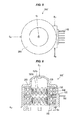
- Figs. 5 to 7 show a structure of a stator of a drive motor for a conventional electrically operated valve.
- a coil 140 wound around a bobbin 130 is retained from above and below by an outer yoke 120 which is provided with magnetic pole teeth 120a, and an inner yoke 122 which is provided with magnetic pole teeth 122a.
- a stator assembly 110 is constructed by bringing two sets of retaining bodies into contact with each other so as to be opposed to each other and positioning them.
- a resin mold 200 is formed around the stator assembly 110 so that only inner surfaces (inward directed surfaces of the stator) of the magnetic pole teeth 120a and 122a, and a lead pin 141 drawn out of the coil 140 are exposed.
- the resin mold 200 is formed, for example, according to the following manner.
- the stator assembly of a stator 100' is set within a metal mold which is not illustrated, and the resin is injected into the metal mold from an upper gate G1 and lower gates, for example, three lower gates G2, G3 and G4.
- the stator assembly 110 is integrally formed with the resin mold 200 and the stator 100' is finished.
- the weld line is a re-melting position of the resin in the resin molding, and a mechanical strength of the re-melting position is lowered in comparison with the other molded surfaces.
- An object of the present invention is to provide a stator of a drive motor for an electrically operated valve, the stator solving the problem mentioned above.
- JP-A-2009-287663 discloses the technique which is provided with the seal member between the lower portion of the stator and the lower portion of the valve main body or the can.
- the structure mentioned above since the moisture does not intrude to the inner side of the stator from the lower portion of the stator, it is not necessary to mold the other portions than the portion which is opposed to the can in the magnetic pole teeth by the resin.
- a stator of a drive motor for an electrically operated valve which is installed to an outer peripheral portion of a can attached to a valve main body having a valve port which is opened and closed by a valve member coupled to a rotor, wherein the stator comprises:
- the resin mold is formed by the molten resin after the stator assembly and the plate are fitted and inserted to a protruding portion of the metal mold.
- the resin mold is formed by the molten resin which is injected from one gate provided in an upper portion of the metal mold opposed to the plate.
- a seal member sealing between the stator and the can or the stator and the valve main body may be provided.
- Fig. 1 is an explanatory view of an electrically operated valve which is equipped with a stator according to the present invention, is a view as seen from a front face of the electrically operated valve and shows only a stator 100 by a vertical cross section, and Fig. 2 is a cross sectional view of the stator according to the present invention.
- the electrically operated valve 1 has a valve main body 10, and a valve member opening and closing between a valve chamber and a valve seat of the valve chamber is arranged within the valve main body 10.
- Two pipings 30 and 32 communicating with the valve chamber are attached to the valve main body 10.
- a can 20 serving as a sealed container is arranged in an upper portion of the valve main body 10.
- a rotor of the motor for driving the electrically operated valve is equipped within the can 20, and a rotation of the rotor is converted into a linear motion via a screw mechanism so as to be transmitted to a valve member.
- the valve member linearly moves, so that a distance between the valve member and the valve seat is adjusted, and a flow rate of a passing cooling medium is controlled.
- valve main body 10 and the can 20 Internal structures of the valve main body 10 and the can 20 are set to well-known appropriate structures.
- a stator 100 of the driving motor is detachably mounted to an outer peripheral portion of the can 20.
- Fig. 3 is a vertical cross sectional perspective view of a stator assembly 110.
- a coil 140 wound around a bobbin 130 is retained from above and below by an outer yoke 120 which is provided with magnetic pole teeth 120a, and an inner yoke 122 which is provided with magnetic pole teeth 122a. Further, the stator assembly 110 is constructed by bringing two sets of the retaining bodies into contact with each other so as to be opposed to each other and positioning them.
- stator 100 is manufactured by setting the stator assembly 110 within a metal mold and injecting a resin so as to be integrated by a resin mold 200, as mentioned later with reference to Fig. 4 .
- annular plate 160 ( Fig. 2 ) is mounted to an upper portion of the stator assembly 110.
- An inner diameter of the plate 160 is set to be substantially the same as an inner diameter of the outer yoke 120 and the inner yoke 122 (that is, an inner diameter of the magnetic pole teeth 120a and the magnetic pole teeth 122a).
- a seal member 180 such as an O-ring is arranged in a lower portion of the resin mold 200, and a seal member stopper 170 for fixing the seal member 180 to the lower portion of the stator 100 is arranged.
- the seal member stopper 170 has four holes in this example, and is attached by inserting a columnar portion formed in the lower portion of the resin mold 200 to the hole so as to form a weld portion 210.
- the seal member 180 prevents moisture from intruding between inner sides of the can 20 and the stator 100.
- Fig. 4 is an explanatory view showing a resin molding process of the stator according to the present invention.
- a center portion of a lower mold 310 is provided with a cylindrical protruding portion 320 which is inserted to the inner diameter portions of the magnetic pole teeth 120a and the magnetic pole teeth 122a of the stator assembly 110, and the stator assembly 110 is fitted to the protruding portion 320.
- a cavity C1 is formed in an outer side of the stator assembly 110.
- a molding molten resin P1 is injected only from one gate G1 which is provided in a top portion of the upper mold 300.
- the annular plate 160 is mounted to the upper portion of the stator assembly 110, and an inner peripheral portion of the plate 160 comes into contact with an outer peripheral portion of the protruding portion 320.
- the molten resin P1 injected from the gate G1 is filled in an outer side of the stator assembly 110 formed by the cavity C1 as shown by an arrow in Fig. 4 without being circulated to an inner side of the stator assembly 110 which is covered with the plate 160.
- a part of the resin intrudes into a complicated internal region of the stator assembly 110 via the outer yoke 120 or gaps which are appropriately provided between the outer yoke 120 and the inner yoke 122, however, does not reach at least side surfaces of the magnetic pole teeth 120a and 122a.
- the weld line is not formed in the outer peripheral portion of the resin mold 200.
- any inflow of the resin into the magnetic pole teeth 120a and the magnetic pole teeth 122a of the stator assembly 110 is not generated. Accordingly, a capacity of the used resin is fixed. Further, an influence applied to the coil by the inflow of the molten resin into the upper coil 140 and the lower coil 142 can be reduced.
- the resin does not flow into the side surfaces of the magnetic pole teeth 120a and the magnetic pole teeth 122a, however, since the seal member 180 sealing between the stator and the can is arranged in the lower portion of the stator 100 (the lower portion of the stator assembly 110), no moisture intrudes into the inner portion of the stator 100.
- the seal member 180 may be structured such as to seal between the stator 100 and the valve main body 10.
- the present invention is provided with the above structures, there can be obtained the preferable stator of the drive motor for the electrically operated valve which has no weld line in the outer peripheral portion of the resin mold.
Landscapes
- Engineering & Computer Science (AREA)
- Power Engineering (AREA)
- Manufacturing & Machinery (AREA)
- Mechanical Engineering (AREA)
- General Engineering & Computer Science (AREA)
- Electrically Driven Valve-Operating Means (AREA)
- Motor Or Generator Frames (AREA)
Abstract
Description
- The present invention relates to a stator of a drive motor which is equipped for an electrically operated valve used for controlling a flow rate of a cooling medium which circulates in a refrigeration cycle.
-
JP-A-2009-287663 - The electrically operated valve is provided with a valve mechanism within a valve main body, and a sealed container called as a can is attached to an upper portion of the valve main body. A rotor of a driving motor is equipped in an inner portion of the can, and a turning force of the rotor is converted into a motion in a linear direction by a screw mechanism so as to operate a valve member. The valve member linearly moves so as to control a valve opening degree. A stator of the driving motor is detachably mounted to an outer peripheral portion of the can.
- The stator is structured such that a stator assembly having a coil wound around magnetic pole teeth of a yoke is set within a metal mold for a resin molding, and a molten resin is supplied into the metal mold, whereby the stator assembly is integrally formed by a synthetic resin.
- In the electrically operated valve mentioned above, in order to make a magnetic gap between the stator and the rotor as small as possible, the magnetic pole teeth of the yoke arranged within the stator are exposed to an inner portion of the stator, however, the other portions than a portion which is opposed to the can in the magnetic pole teeth are molded by the resin, so as to prevent a moisture from intruding into the coil within the stator from an external portion.
- In
JP-A-2009-287663 - In
JP-A-2000-262024 -
Figs. 5 to 7 show a structure of a stator of a drive motor for a conventional electrically operated valve. Acoil 140 wound around abobbin 130 is retained from above and below by anouter yoke 120 which is provided withmagnetic pole teeth 120a, and aninner yoke 122 which is provided withmagnetic pole teeth 122a. Further, astator assembly 110 is constructed by bringing two sets of retaining bodies into contact with each other so as to be opposed to each other and positioning them. In thestator assembly 110, aresin mold 200 is formed around thestator assembly 110 so that only inner surfaces (inward directed surfaces of the stator) of themagnetic pole teeth lead pin 141 drawn out of thecoil 140 are exposed. - The
resin mold 200 is formed, for example, according to the following manner. In other words, the stator assembly of a stator 100' is set within a metal mold which is not illustrated, and the resin is injected into the metal mold from an upper gate G1 and lower gates, for example, three lower gates G2, G3 and G4. - The
stator assembly 110 is integrally formed with theresin mold 200 and the stator 100' is finished. - As mentioned above, in an inner peripheral surface of the stator 100', it is necessary to circulate the resin in the other portions than the inner surfaces of the
magnetic pole teeth - Therefore, in the conventional manufacturing method, since the molding operation is carried out in the multiple points of gates (for example, four gates) which are provided in the upper and lower sides of the metal mold, so that the molten resin is circulated around the stator, a weld line WL is generated in an outer peripheral portion of the
resin mold 200. - The weld line is a re-melting position of the resin in the resin molding, and a mechanical strength of the re-melting position is lowered in comparison with the other molded surfaces.
- In the case that an electrically operated valve using the stator is mounted, for example, to a motor vehicle or a marine vessel, an environmental temperature range in an air temperature and a low temperature becomes large, and a temperature fluctuation do damage to the coil resin part. Therefore, a crack is generated in the weld line portion, and there is a risk that a deterioration of an insulating performance is caused by a water intrusion from the crack position.
- An object of the present invention is to provide a stator of a drive motor for an electrically operated valve, the stator solving the problem mentioned above.
-
JP-A-2009-287663 - The present invention is made by taking the point mentioned above into consideration. In order to achieve the object mentioned above, according to the present invention, there is provided a stator of a drive motor for an electrically operated valve which is installed to an outer peripheral portion of a can attached to a valve main body having a valve port which is opened and closed by a valve member coupled to a rotor,
wherein the stator comprises: - a stator assembly which is provided with a yoke having magnetic pole teeth and a coil; and
- a resin mold which integrally forms the stator assembly by injecting a molten resin within a metal mold, and
- a plate having an inner diameter which is substantially the same as an inner diameter of the magnetic pole teeth, and arranged in an upper surface of the stator assembly so as to prevent the molten resin from flowing to the magnetic pole teeth side.
- It is desirable that the resin mold is formed by the molten resin after the stator assembly and the plate are fitted and inserted to a protruding portion of the metal mold.
- Further, it is desirable that the resin mold is formed by the molten resin which is injected from one gate provided in an upper portion of the metal mold opposed to the plate.
- Further, a seal member sealing between the stator and the can or the stator and the valve main body may be provided.
-
-
Fig. 1 is an explanatory view of an electrically operated valve which is equipped with a stator of a drive motor for an electrically operated valve according to an embodiment of the present invention; -
Fig. 2 is a vertical cross sectional view of the stator of the drive motor for the electrically operated valve according to the embodiment of the present invention; -
Fig. 3 is a vertical cross sectional perspective view of a stator assembly according to the embodiment of the present invention; -
Fig. 4 is an explanatory view showing a molding method of the stator according to the embodiment of the present invention; -
Fig. 5 is a plan view of a conventional stator; -
Fig. 6 is a vertical cross sectional view of the conventional stator; and -
Fig. 7 is a front elevational view of the conventional stator. -
Fig. 1 is an explanatory view of an electrically operated valve which is equipped with a stator according to the present invention, is a view as seen from a front face of the electrically operated valve and shows only astator 100 by a vertical cross section, andFig. 2 is a cross sectional view of the stator according to the present invention. - The electrically operated
valve 1 has a valvemain body 10, and a valve member opening and closing between a valve chamber and a valve seat of the valve chamber is arranged within the valvemain body 10. Twopipings main body 10. - A can 20 serving as a sealed container is arranged in an upper portion of the valve
main body 10. A rotor of the motor for driving the electrically operated valve is equipped within thecan 20, and a rotation of the rotor is converted into a linear motion via a screw mechanism so as to be transmitted to a valve member. The valve member linearly moves, so that a distance between the valve member and the valve seat is adjusted, and a flow rate of a passing cooling medium is controlled. - Internal structures of the valve
main body 10 and thecan 20 are set to well-known appropriate structures. - A
stator 100 of the driving motor is detachably mounted to an outer peripheral portion of thecan 20.Fig. 3 is a vertical cross sectional perspective view of astator assembly 110. - A
coil 140 wound around abobbin 130 is retained from above and below by anouter yoke 120 which is provided withmagnetic pole teeth 120a, and aninner yoke 122 which is provided withmagnetic pole teeth 122a. Further, thestator assembly 110 is constructed by bringing two sets of the retaining bodies into contact with each other so as to be opposed to each other and positioning them. - Further, the
stator 100 is manufactured by setting thestator assembly 110 within a metal mold and injecting a resin so as to be integrated by aresin mold 200, as mentioned later with reference toFig. 4 . - When injecting the resin, an annular plate 160 (
Fig. 2 ) is mounted to an upper portion of thestator assembly 110. An inner diameter of theplate 160 is set to be substantially the same as an inner diameter of theouter yoke 120 and the inner yoke 122 (that is, an inner diameter of themagnetic pole teeth 120a and themagnetic pole teeth 122a). - Further, a
seal member 180 such as an O-ring is arranged in a lower portion of theresin mold 200, and a seal member stopper 170 for fixing theseal member 180 to the lower portion of thestator 100 is arranged. - The
seal member stopper 170 has four holes in this example, and is attached by inserting a columnar portion formed in the lower portion of theresin mold 200 to the hole so as to form aweld portion 210. - The
seal member 180 prevents moisture from intruding between inner sides of thecan 20 and thestator 100. -
Fig. 4 is an explanatory view showing a resin molding process of the stator according to the present invention. - A center portion of a
lower mold 310 is provided with a cylindrical protrudingportion 320 which is inserted to the inner diameter portions of themagnetic pole teeth 120a and themagnetic pole teeth 122a of thestator assembly 110, and thestator assembly 110 is fitted to the protrudingportion 320. When anupper mold 300 and thelower mold 310 are closed, a cavity C1 is formed in an outer side of thestator assembly 110. A molding molten resin P1 is injected only from one gate G1 which is provided in a top portion of theupper mold 300. - In the stator according to the present invention, the
annular plate 160 is mounted to the upper portion of thestator assembly 110, and an inner peripheral portion of theplate 160 comes into contact with an outer peripheral portion of the protrudingportion 320. - Accordingly, the molten resin P1 injected from the gate G1 is filled in an outer side of the
stator assembly 110 formed by the cavity C1 as shown by an arrow inFig. 4 without being circulated to an inner side of thestator assembly 110 which is covered with theplate 160. A part of the resin intrudes into a complicated internal region of thestator assembly 110 via theouter yoke 120 or gaps which are appropriately provided between theouter yoke 120 and theinner yoke 122, however, does not reach at least side surfaces of themagnetic pole teeth - As mentioned above, since the resin P1 is filled only from the gate G1 at one position, the weld line is not formed in the outer peripheral portion of the
resin mold 200. - Further, any inflow of the resin into the
magnetic pole teeth 120a and themagnetic pole teeth 122a of thestator assembly 110 is not generated. Accordingly, a capacity of the used resin is fixed. Further, an influence applied to the coil by the inflow of the molten resin into theupper coil 140 and the lower coil 142 can be reduced. - As mentioned above, the resin does not flow into the side surfaces of the
magnetic pole teeth 120a and themagnetic pole teeth 122a, however, since theseal member 180 sealing between the stator and the can is arranged in the lower portion of the stator 100 (the lower portion of the stator assembly 110), no moisture intrudes into the inner portion of thestator 100. - The
seal member 180 may be structured such as to seal between thestator 100 and the valvemain body 10. - Further, in the case that a seal member sealing between the stator and the can is provided in the lower portion of the can, in place of the
seal member 180 provided in the lower portion of thestator 100, it is not necessary to arrange the seal member in the stator. Further, in the case that the lower portion of the stator is extended so as to cover the upper side surface of the valve main body, and the seal member sealing between the stator and the valve main body is provided in the upper side surface of the valve main body, it is not necessary to arrange the seal member in the stator in the same manner. - Since the present invention is provided with the above structures, there can be obtained the preferable stator of the drive motor for the electrically operated valve which has no weld line in the outer peripheral portion of the resin mold.
Claims (4)
- A stator (100) of a drive motor for an electrically operated valve (1) which is installed to an outer peripheral portion of a can (20) attached to a valve main body (10) having a valve port which is opened and closed by a valve member coupled to a rotor,
characterized in that said stator (100) comprises:a stator assembly (110) which is provided with a yoke (120, 122) having magnetic pole teeth (120a, 122a) and a coil (140); anda resin mold (200) which integrally forms said stator assembly (110) by injecting a molten resin (P1) within a metal mold (300, 310), andthat said stator (100) comprises:a plate (160) having an inner diameter which is substantially the same as an inner diameter of said magnetic pole teeth (120a, 122a), and arranged in an upper surface of the stator assembly (110) so as to prevent the molten resin (P1) from flowing to the magnetic pole teeth (120a, 122a) side. - The stator (100) of the drive motor for the electrically operated valve (1) according to claim 1, characterized in that said resin mold (200) is formed by the molten resin (P1) after said stator assembly (110) and said plate (160) are fitted and inserted to a protruding portion (320) of the metal mold (300, 310).
- The stator (100) of the drive motor for the electrically operated valve (1) according to claim 1 or 2, characterized in that said resin mold (200) is formed by the molten resin (P1) which is injected from one gate (G1) provided in an upper portion of the metal mold (300, 310) opposed to the plate (160).
- The stator (100) of the drive motor for the electrically operated valve (1) according to any one of claims 1 to 3, characterized in that the stator further comprises a seal member (180) sealing between said stator and said can (20) or said stator and said valve main body (10).
Applications Claiming Priority (1)
| Application Number | Priority Date | Filing Date | Title |
|---|---|---|---|
| JP2012100111A JP5965712B2 (en) | 2012-04-25 | 2012-04-25 | Stator of drive motor for electric valve |
Publications (2)
| Publication Number | Publication Date |
|---|---|
| EP2658088A2 true EP2658088A2 (en) | 2013-10-30 |
| EP2658088A3 EP2658088A3 (en) | 2017-03-15 |
Family
ID=47998209
Family Applications (1)
| Application Number | Title | Priority Date | Filing Date |
|---|---|---|---|
| EP13160269.0A Withdrawn EP2658088A3 (en) | 2012-04-25 | 2013-03-21 | Stator of drive motor for electrically operated valve |
Country Status (5)
| Country | Link |
|---|---|
| US (1) | US9385564B2 (en) |
| EP (1) | EP2658088A3 (en) |
| JP (1) | JP5965712B2 (en) |
| KR (1) | KR101998426B1 (en) |
| CN (1) | CN103375628B (en) |
Cited By (2)
| Publication number | Priority date | Publication date | Assignee | Title |
|---|---|---|---|---|
| EP3361606A1 (en) * | 2017-02-09 | 2018-08-15 | Johnson Electric S.A. | Linear stepper motor, device and method for manufacturing the linear stepper motor |
| EP4224681A4 (en) * | 2020-09-30 | 2024-11-13 | Fujikoki Corporation | Stator unit and electric valve |
Families Citing this family (14)
| Publication number | Priority date | Publication date | Assignee | Title |
|---|---|---|---|---|
| JP6160730B1 (en) * | 2016-03-25 | 2017-07-12 | ダイキン工業株式会社 | Rotor and method for manufacturing the same |
| FR3062701B1 (en) * | 2017-02-06 | 2019-06-07 | Mmt ag | MOTORIZED VALVE WITH BOISSEAU |
| KR102452163B1 (en) * | 2017-08-03 | 2022-10-11 | 엘지이노텍 주식회사 | Motor |
| CN111255939A (en) * | 2018-11-30 | 2020-06-09 | 浙江三花智能控制股份有限公司 | an electromagnetic coil |
| US20240269906A1 (en) * | 2018-11-30 | 2024-08-15 | Zhejing Sanhua Intelligent Controls Co., Ltd. | Electromagnetic coil, mold, and electromagnetic coil manufacturing method |
| JP7161764B2 (en) * | 2019-03-22 | 2022-10-27 | 株式会社テージーケー | electric valve |
| JP7260159B2 (en) * | 2019-06-28 | 2023-04-18 | 株式会社テージーケー | Stator unit, motor-operated valve, and stator unit manufacturing method |
| JP7462282B2 (en) * | 2019-08-22 | 2024-04-05 | 株式会社テージーケー | Motor-operated valve |
| JP7280622B2 (en) * | 2020-08-28 | 2023-05-24 | 株式会社不二工機 | Stator unit, motor-operated valve, and stator unit manufacturing method |
| JP7418838B2 (en) * | 2021-06-14 | 2024-01-22 | 株式会社不二工機 | Stator unit, electric valve, and method for manufacturing the stator unit |
| CN115596851A (en) * | 2021-07-09 | 2023-01-13 | 浙江三花汽车零部件有限公司(Cn) | Electrically operated valve and assembling method thereof |
| CN216487648U (en) * | 2021-12-15 | 2022-05-10 | 浙江盾安人工环境股份有限公司 | Coil assembly and electronic expansion valve having the same |
| CN114484050B (en) * | 2022-04-15 | 2022-10-14 | 广东威灵电机制造有限公司 | Electronic expansion valve and refrigeration equipment |
| DE102022128604B3 (en) | 2022-10-28 | 2024-03-14 | Dr. Ing. H.C. F. Porsche Aktiengesellschaft | Tool, in particular injection tool for producing an electrical machine |
Citations (5)
| Publication number | Priority date | Publication date | Assignee | Title |
|---|---|---|---|---|
| JP2000262024A (en) | 1999-03-05 | 2000-09-22 | Fuji Koki Corp | Method of manufacturing electromagnetic actuator, electromagnetic actuator, and electric valve provided with electromagnetic actuator |
| EP1089416A1 (en) * | 1999-04-20 | 2001-04-04 | Mitsubishi Denki Kabushiki Kaisha | Motor shaft for rotation/direct action converting motor and method of manufacturing the motor shaft |
| US20070086907A1 (en) * | 2005-10-19 | 2007-04-19 | Stephan Oberle | Gearwheel and method for manufacturing a gearwheel |
| JP2009287663A (en) | 2008-05-29 | 2009-12-10 | Fuji Koki Corp | Flow rate control valve |
| US20090315218A1 (en) * | 2008-06-24 | 2009-12-24 | Suzuki Motor Corporation | Injection mold and molding method for resin molding |
Family Cites Families (5)
| Publication number | Priority date | Publication date | Assignee | Title |
|---|---|---|---|---|
| US4480614A (en) * | 1980-10-06 | 1984-11-06 | Toyota Jidosha K.K. | Idling speed control device of an internal combustion engine |
| JPH06335226A (en) * | 1993-05-18 | 1994-12-02 | Asmo Co Ltd | Pm type stepping motor |
| US6581903B2 (en) * | 1998-02-24 | 2003-06-24 | Mitsubishi Denki Kabushiki Kaisha | Electrical flow control valve |
| KR101055516B1 (en) * | 2003-04-02 | 2011-08-08 | 가부시기가이샤 후지고오키 | Motorized valve |
| US20060175565A1 (en) * | 2005-02-08 | 2006-08-10 | Roy Nungesser | Electric motor driven valve assembly having stator sealing |
-
2012
- 2012-04-25 JP JP2012100111A patent/JP5965712B2/en active Active
-
2013
- 2013-03-18 US US13/845,867 patent/US9385564B2/en active Active
- 2013-03-21 EP EP13160269.0A patent/EP2658088A3/en not_active Withdrawn
- 2013-03-28 KR KR1020130033310A patent/KR101998426B1/en active Active
- 2013-04-24 CN CN201310146403.2A patent/CN103375628B/en active Active
Patent Citations (5)
| Publication number | Priority date | Publication date | Assignee | Title |
|---|---|---|---|---|
| JP2000262024A (en) | 1999-03-05 | 2000-09-22 | Fuji Koki Corp | Method of manufacturing electromagnetic actuator, electromagnetic actuator, and electric valve provided with electromagnetic actuator |
| EP1089416A1 (en) * | 1999-04-20 | 2001-04-04 | Mitsubishi Denki Kabushiki Kaisha | Motor shaft for rotation/direct action converting motor and method of manufacturing the motor shaft |
| US20070086907A1 (en) * | 2005-10-19 | 2007-04-19 | Stephan Oberle | Gearwheel and method for manufacturing a gearwheel |
| JP2009287663A (en) | 2008-05-29 | 2009-12-10 | Fuji Koki Corp | Flow rate control valve |
| US20090315218A1 (en) * | 2008-06-24 | 2009-12-24 | Suzuki Motor Corporation | Injection mold and molding method for resin molding |
Cited By (3)
| Publication number | Priority date | Publication date | Assignee | Title |
|---|---|---|---|---|
| EP3361606A1 (en) * | 2017-02-09 | 2018-08-15 | Johnson Electric S.A. | Linear stepper motor, device and method for manufacturing the linear stepper motor |
| US10601294B2 (en) | 2017-02-09 | 2020-03-24 | Johnson Electric International AG | Linear stepper motor, device and method for manufacturing the linear stepper motor |
| EP4224681A4 (en) * | 2020-09-30 | 2024-11-13 | Fujikoki Corporation | Stator unit and electric valve |
Also Published As
| Publication number | Publication date |
|---|---|
| JP2013229994A (en) | 2013-11-07 |
| US9385564B2 (en) | 2016-07-05 |
| KR20130120383A (en) | 2013-11-04 |
| JP5965712B2 (en) | 2016-08-10 |
| CN103375628B (en) | 2016-12-28 |
| KR101998426B1 (en) | 2019-07-09 |
| EP2658088A3 (en) | 2017-03-15 |
| CN103375628A (en) | 2013-10-30 |
| US20130285481A1 (en) | 2013-10-31 |
Similar Documents
| Publication | Publication Date | Title |
|---|---|---|
| US9385564B2 (en) | Stator of drive motor for electrically operated valve | |
| KR101483300B1 (en) | Rotor core for motorized valve, rotor feed screw and rotor manufacturing method | |
| US10260510B2 (en) | Fan, motor and manufacturing method thereof | |
| EP2983277A2 (en) | Electromagnetic drive coil unit and molding method thereof | |
| CN114096175B (en) | Fastener stringer, method for producing the same, and slide fastener | |
| JP2016220403A (en) | Stator unit and motor-operated valve using the same | |
| US20140299802A1 (en) | Solenoid Valve, Battery of Solenoid Valves, Method of Manufacturing a Solenoid Valve, and Mold | |
| KR101857532B1 (en) | Electronic expansion valve and coil device for same | |
| JP5399343B2 (en) | Permanent magnet resin sealing method and laminated iron core manufactured by the method | |
| JP2008125353A5 (en) | ||
| CN104135101B (en) | Brushless plastic cement motor and its manufacture method | |
| JPH08296758A (en) | Flow control valve and its manufacture | |
| US20090300918A1 (en) | Methods of manufacturing rotor core for motor-driven valve, rotor feed screw and rotor | |
| US20140043020A1 (en) | Rotator for an angle sensor | |
| KR102561189B1 (en) | Waterproof step motor using magnetic field repulsion between rotating magnets | |
| JP4563088B2 (en) | Electromagnetic actuator | |
| JP2014014271A (en) | Resin sealing method of permanent magnet and laminated core manufactured by that method | |
| CN207122582U (en) | Valve mechanism and electromagnetic valve | |
| JP5560138B2 (en) | Resin sealing method for permanent magnet and resin sealing device used in the method | |
| CN114905770B (en) | Blade forming method and mould | |
| JP6129652B2 (en) | Manufacturing method of seal parts | |
| JP2015006052A (en) | Stator unit | |
| KR200280604Y1 (en) | Valve system for injection molding | |
| JP6239323B2 (en) | Stator unit | |
| KR102089960B1 (en) | Valve assembly and manufacturing method the same |
Legal Events
| Date | Code | Title | Description |
|---|---|---|---|
| PUAI | Public reference made under article 153(3) epc to a published international application that has entered the european phase |
Free format text: ORIGINAL CODE: 0009012 |
|
| AK | Designated contracting states |
Kind code of ref document: A2 Designated state(s): AL AT BE BG CH CY CZ DE DK EE ES FI FR GB GR HR HU IE IS IT LI LT LU LV MC MK MT NL NO PL PT RO RS SE SI SK SM TR |
|
| AX | Request for extension of the european patent |
Extension state: BA ME |
|
| PUAL | Search report despatched |
Free format text: ORIGINAL CODE: 0009013 |
|
| AK | Designated contracting states |
Kind code of ref document: A3 Designated state(s): AL AT BE BG CH CY CZ DE DK EE ES FI FR GB GR HR HU IE IS IT LI LT LU LV MC MK MT NL NO PL PT RO RS SE SI SK SM TR |
|
| AX | Request for extension of the european patent |
Extension state: BA ME |
|
| RIC1 | Information provided on ipc code assigned before grant |
Ipc: H02K 1/14 20060101AFI20170206BHEP Ipc: H02K 5/08 20060101ALN20170206BHEP Ipc: H02K 15/12 20060101ALI20170206BHEP Ipc: H02K 15/14 20060101ALI20170206BHEP |
|
| STAA | Information on the status of an ep patent application or granted ep patent |
Free format text: STATUS: REQUEST FOR EXAMINATION WAS MADE |
|
| STAA | Information on the status of an ep patent application or granted ep patent |
Free format text: STATUS: EXAMINATION IS IN PROGRESS |
|
| 17P | Request for examination filed |
Effective date: 20170807 |
|
| RBV | Designated contracting states (corrected) |
Designated state(s): AL AT BE BG CH CY CZ DE DK EE ES FI FR GB GR HR HU IE IS IT LI LT LU LV MC MK MT NL NO PL PT RO RS SE SI SK SM TR |
|
| 17Q | First examination report despatched |
Effective date: 20170912 |
|
| STAA | Information on the status of an ep patent application or granted ep patent |
Free format text: STATUS: THE APPLICATION IS DEEMED TO BE WITHDRAWN |
|
| 18D | Application deemed to be withdrawn |
Effective date: 20180801 |