EP2657923A2 - System und Verfahren zum Anzeigen eines zeitweise verschobenen Landebahnschwellenwerts und Flugzeuglandungszielpunkt - Google Patents
System und Verfahren zum Anzeigen eines zeitweise verschobenen Landebahnschwellenwerts und Flugzeuglandungszielpunkt Download PDFInfo
- Publication number
- EP2657923A2 EP2657923A2 EP13162816.6A EP13162816A EP2657923A2 EP 2657923 A2 EP2657923 A2 EP 2657923A2 EP 13162816 A EP13162816 A EP 13162816A EP 2657923 A2 EP2657923 A2 EP 2657923A2
- Authority
- EP
- European Patent Office
- Prior art keywords
- runway
- data
- display
- threshold
- aircraft
- Prior art date
- Legal status (The legal status is an assumption and is not a legal conclusion. Google has not performed a legal analysis and makes no representation as to the accuracy of the status listed.)
- Withdrawn
Links
Images


Classifications
-
- G—PHYSICS
- G08—SIGNALLING
- G08G—TRAFFIC CONTROL SYSTEMS
- G08G5/00—Traffic control systems for aircraft, e.g. air-traffic control [ATC]
- G08G5/0004—Transmission of traffic-related information to or from an aircraft
- G08G5/0013—Transmission of traffic-related information to or from an aircraft with a ground station
-
- G—PHYSICS
- G08—SIGNALLING
- G08G—TRAFFIC CONTROL SYSTEMS
- G08G5/00—Traffic control systems for aircraft, e.g. air-traffic control [ATC]
- G08G5/0017—Arrangements for implementing traffic-related aircraft activities, e.g. arrangements for generating, displaying, acquiring or managing traffic information
- G08G5/0021—Arrangements for implementing traffic-related aircraft activities, e.g. arrangements for generating, displaying, acquiring or managing traffic information located in the aircraft
-
- G—PHYSICS
- G08—SIGNALLING
- G08G—TRAFFIC CONTROL SYSTEMS
- G08G5/00—Traffic control systems for aircraft, e.g. air-traffic control [ATC]
- G08G5/02—Automatic approach or landing aids, i.e. systems in which flight data of incoming planes are processed to provide landing data
- G08G5/025—Navigation or guidance aids
Definitions
- the exemplary embodiments described herein generally relate to displaying a temporarily displaced threshold and aiming point, and more particularly to updating displayed runway markings modified in response to a Notice to Airmen (NOTAM).
- NOTAM Notice to Airmen
- the approach to landing and touch down on the runway of an aircraft is probably the most challenging task a pilot undertakes during normal operation.
- the aircraft approaches the runway within an envelope of attitude, course, speed, and rate of descent limits.
- the course limits include, for example, both lateral limits and glide slope limits.
- An approach outside of this envelope can result in an undesirable positioning of the aircraft with respect to the runway, resulting in possibly discontinuance of the landing attempt.
- the pilot is provided or determines the runway threshold (end of the usable runway) and aiming point (for the aircraft).
- the aiming point is further down the runway so the runway between the threshold and the aiming point is available for touchdown in case the pilot undershoots the aiming point.
- Synthetic vision systems are currently certified for situation awareness purposes in commercial and business aviation applications with no additional landing credit for going below published minimum.
- Such a display system when used in conjunction with Enhanced Vision Systems, is known to improve a pilot's overall situational awareness and reduce flight technical errors.
- NOTAMs bring information about sudden/immediate changes and temporary changes that will exist for a short time only.
- the legacy NOTAM messages (the current system of a text note which can be distributed by basic teletype networks such as the Aeronautical Fixed Telecommunication Network) largely escape the digital processing data chain and as a result the contents of a database on-board the aircraft may be incorrect (superseded by NOTAM).
- Display Systems such as the Synthetic Vision Systems (SVS), Airport Moving Maps, top down and side view maps may not be displaying up to date or complete data.
- SVS Synthetic Vision Systems
- Airport Moving Maps Airport Moving Maps
- top down and side view maps may not be displaying up to date or complete data.
- Advisory and Warning systems like Smart Landing/RAAS may mislead the pilot based on database information on which they provide an alert due to not being in sync with the temporary NOTAM, and for not considering the full runway length available in accordance with the airport database, and therefore, will raise an alert when the pilot tries the new computed aiming point. In doing so, the display is providing misleading or incomplete data to the pilot. If the threshold of the runway is temporarily displaced, the display still continues to show full runway length available. Though the information might be available through ATIS or even Digital NOTAMs on a separate display, there are quite a few opportunities for the pilot to miss the data.
- Pilot workload is increased as he has to take a note of this or visualize the effect of the change. For example, manufactures of SVS systems are seeking lower landing minima (Operational Credit) using improved symbology.
- the pilot can visually use the flight path symbol (FPS) and flight director (FD) alignment with the aiming point markers of the arrival runway to verify that the aircraft continues to move towards that point of runway during the approach.
- the runway threshold is displaced by a NOTAM
- the pilot will need to mentally visualize where the aiming point markers will now be depicted based on the NOTAM, which not only increases the pilot work load, the pilot estimate of aiming point markers may not be accurate.
- the pilot may aim at the original aiming point markers if he missed the NOTAM. This may put the aircraft glide path in the way of obstructions or the aircraft may land on the part of the runway that is not capable of handling aircraft landings. Therefore, depicting the Actual runway (incorporating the NOTAM changes) and notifying the pilot that the information came from a NOTAM is all the more important for SVS.
- NOTAMs are often hard to read and sometimes there are so many of them that don't apply to pilots that they just ignore all of them. Failure to get the current pertinent NOTAMs may result in undesired results.
- NOTAMs provide information about immediate and temporary changes. Determining which NOTAM is applicable to a given flight typically is not easy and requires a major effort on the part of the pilot or, in the case of airline operations, the personnel who put together the route documents for the pilot's flights.
- NOTAM The legacy NOTAM messages largely escape the digital processing data chain and as a result, the contents of a database on-board the aircraft may be 'superseded by NOTAM'. In known systems, the task of remembering which information has been overridden becomes a task for the pilots.
- a method and system are provided for receiving a NOTAM and storing information relating to flight information, e.g., the distance of a temporarily displaced threshold for a runway. When that runway is selected for approach and landing, the temporarily displaced threshold and new aiming point are automatically displayed.
- a method of displaying information on a display of an aircraft comprises receiving NOTAM data; storing the data; selecting a desired flight path; identifying visual information related to the flight path; modifying the visual information in response to the NOTAM data; and displaying the modified visual information.
- a system within an aircraft comprises a database; a display; and a flight management system coupled to the database and the display, and configured to store data from a received NOTAM; select a target runway having markers indicating the location of a runway threshold, and an aiming point on the runway for the aircraft in performing a landing; determine the positioning of modified markers, and a modified aiming point to be displayed in accordance with the data; and display on the display the runway including the modified markers and modified aiming point.
- a system within an aircraft including a display, the system comprises a database; and a processor coupled to the display and the database, and configured to store data from a received NOTAM in the database; determine a current position of the aircraft; retrieve visual markings related to a desired flight path from the database; update the visual markings by the processor in response to the data; and display the updated visual markings on the display.
- FIG. 1 is a functional block diagram of a known flight display system
- FIG. 2 is an exemplary image that may be rendered on the flight display system of FIG. 1 ;
- FIG. 3 is a flow chart of a method in accordance with an exemplary embodiment
- FIGS. 4-8 are exemplary images displayed in accordance with exemplary embodiments.
- FIG. 9 is an exemplary image displaying a NOTAM in accordance with an exemplary embodiment.
- FIG. 10 is a side view of a flight plan modified in accordance with an exemplary embodiment.
- a system and method are disclosed herein for receiving a NOTAM and storing information relating to the distance of a displaced threshold for a runway.
- the runway including the displaced threshold and a new aim point are automatically displayed.
- the change made to the display using NOTAM data can be indicated to the pilot by distinct symbology, particular color, or by using an icon or an annunciation.
- NOTAM is filed with an aviation authority to alert aircraft pilots of any hazards en route or at a specific location. While there are several types of NOTAMS, one type disseminates information for all navigational facilities that are part of the National Airspace System (NAS) including all public use airports, seaplane bases, and heliports listed in the Airport/Facility Directory (A/FD), for example, such information as whether or not an airport or a certain facility is usable. NOTAMS may include such data as taxiway closures, personnel and equipment near or crossing runways, and airport lighting aids that do not affect instrument approach criteria.
- NAS National Airspace System
- A/FD Airport/Facility Directory
- a digital NOTAM is a dataset that contains NOTAM information in a structured format. It can be fully interpreted by the onboard system without human intervention. It is geo-referenced, temporal, linked to static data, transformable, query enabled and electronically distributable.
- a displaced threshold may be necessary, for example, due to construction off the end of the runway. Knowing the displaced threshold distance, displays, for example, a synthetic vision system, airport moving map, vertical situation display, or interactive navigation, will depict that runway with a displaced threshold markings (or temporary displaced threshold markings) and also update the distance remaining signs accordingly. Distance remaining signs are signs typically on both sides of the runway indicating the distance remaining to the far end of the runway. This distance remaining indication assists the pilot in determining a rate of deceleration after touchdown. An indication to the pilot that the change may be made using NOTAM data through particular color, annunciation, icon or distinct symbology.
- the database can be updated for the effective period of the NOTAM and all displays are changed as the source data has changed.
- a temporary overriding database of only the NOTAM indicated changes could be created dynamically and after a record of the same position is fetched from the database, it can be cross checked against the NOTAM database created for updates.
- an icon could be placed on the display to depict the NOTAM since the digital NOTAM's are geo-referenced (having known coordinates).
- In-serviceable NAV aids could be either removed from the map display or depicted using a different icon based on the NOTAM. Updates issued to Restricted areas or Danger zones could be reflected on the airspace display.
- a caution and warning system could be updated with the NOTAM data for alerting the pilot.
- the waypoint of a plurality of waypoints in the flight plan may comprise a unique format for alerting the pilot of modified flight information, for example, a temporarily displaced threshold.
- Weather information available through SNOTAMS could be depicted on the Airport moving maps for graphical visualization of airport surface conditions or over laid on the existing weather displays.
- ATIS Automatic Terminal Information Service
- weather information which runways are active, available approaches, and any other information required by the pilots, such as important NOTAMs out of order could be alerted to pilot through crew alerting messages.
- an embodiment of a system or a component may employ various integrated circuit components, e.g., memory elements, digital signal processing elements, logic elements, look-up tables, or the like, which may carry out a variety of functions under the control of one or more microprocessors or other control devices.
- integrated circuit components e.g., memory elements, digital signal processing elements, logic elements, look-up tables, or the like, which may carry out a variety of functions under the control of one or more microprocessors or other control devices.
- the system 100 includes a user interface 102, a processor 104, one or more terrain/airport databases 106, one or more navigation databases 108, various optional sensors 112 (for the cockpit display version), various external data sources 114, and a display device 116.
- the user interface 102 and the display device 116 may be combined in the same device, for example, a touch pad.
- the user interface 102 is in operable communication with the processor 104 and is configured to receive input from a user 109 (e.g., a pilot) and, in response to the user input, supply command signals to the processor 104.
- a user 109 e.g., a pilot
- the user interface 102 may be any one, or combination, of various known user interface devices including, but not limited to, a cursor control device (not shown), such as a mouse, a trackball, or joystick, and/or a keyboard, one or more buttons, switches, or knobs.
- a cursor control device such as a mouse, a trackball, or joystick
- a keyboard such as a mouse, a trackball, or joystick
- buttons, switches, or knobs such as a keyboard, one or more buttons, switches, or knobs.
- the processor 104 may be any one of numerous known general-purpose microprocessors or an application specific processor that operates in response to program instructions.
- the processor 104 includes on-board RAM (random access memory) 103, and on-board ROM (read only memory) 105.
- the program instructions that control the processor 104 may be stored in either or both the RAM 103 and the ROM 105.
- the operating system software may be stored in the ROM 105, whereas various operating mode software routines and various operational parameters may be stored in the RAM 103. It will be appreciated that this is merely exemplary of one scheme for storing operating system software and software routines, and that various other storage schemes may be implemented.
- the processor 104 may be implemented using various other circuits, not just a programmable processor. For example, digital logic circuits and analog signal processing circuits could also be used.
- the processor 104 is in operable communication with the terrain/taxiway databases 106, the navigation databases 108, and the display device 116, and is coupled to receive various types of aircraft state data from the various sensors 112, and various other environment related data from the external data sources 114.
- the processor 104 is configured, in response to the inertial data and the avionics-related data, to selectively retrieve terrain data from one or more of the terrain/airport databases 106 and navigation data from one or more of the navigation databases 108, and to supply appropriate display commands to the display device 116.
- the display device 116 in response to the display commands from, for example, a touch screen, keypad, cursor control, line select, concentric knobs, voice control, and datalink message, selectively renders various types of textual, graphic, and/or iconic information.
- the preferred manner in which the textual, graphic, and/or iconic information are rendered by the display device 116 will be described in more detail further below. Before doing so, however, a brief description of the databases 106, 108, the sensors 112, and the external data sources 114, at least in the depicted embodiment, will be provided.
- the terrain/taxiway databases 106 include various types of data representative of the surface over which the aircraft is taxing, the terrain over which the aircraft is flying, and the navigation databases 108 include various types of navigation-related data.
- These navigation-related data include various flight plan related data such as, for example, waypoints, distances between waypoints, headings between waypoints, data related to different airports, navigational aids, obstructions, special use airspace, political boundaries, communication frequencies, and aircraft approach information.
- terrain/taxiway databases 106 and the navigation databases 108 are, for clarity and convenience, shown as being stored separate from the processor 104, all or portions of either or both of these databases 106, 108 could be loaded into the RAM 103, or integrally formed as part of the processor 104, and/or RAM 103, and/or ROM 105.
- the terrain/taxiway databases 106 and navigation databases 108 could also be part of a device or system that is physically separate from the system 100.
- the sensors 112 may be implemented using various types of sensors, systems, and or subsystems, now known or developed in the future, for supplying various types of aircraft state data.
- the state data may also vary, but preferably include data representative of the geographic position of the aircraft and also other data such as, for example, aircraft speed, heading, altitude, and attitude.
- the number and type of external data sources 114 may also vary, but typically include for example, a GPS receiver 122, other avionics receivers 118, and a data link unit 119.
- the other avionics receivers would include, for example, a terrain avoidance and warning system (TAWS), a traffic and collision avoidance system (TCAS), a runway awareness and advisory system (RAAS), a flight director, and a navigation computer.
- TAWS terrain avoidance and warning system
- TCAS traffic and collision avoidance system
- RAAS runway awareness and advisory system
- flight director and a navigation computer.
- the GPS receiver 122 is a multi-channel receiver, with each channel tuned to receive one or more of the GPS broadcast signals transmitted by the constellation of GPS satellites (not illustrated) orbiting the earth. Each GPS satellite encircles the earth two times each day, and the orbits are arranged so that at least four satellites are always within line of sight from almost anywhere on the earth.
- the GPS receiver 122 upon receipt of the GPS broadcast signals from at least three, and preferably four, or more of the GPS satellites, determines the distance between the GPS receiver 122 and the GPS satellites and the position of the GPS satellites. Based on these determinations, the GPS receiver 122, using a technique known as trilateration, determines, for example, aircraft position, groundspeed, and ground track angle. These data may be supplied to the processor 104, which may determine aircraft glide slope deviation therefrom. Preferably, however, the GPS receiver 122 is configured to determine, and supply data representative of, aircraft glide slope deviation to the processor 104.
- the display device 116 in response to display commands supplied from the processor 104, selectively renders various textual, graphic, and/or iconic information, and thereby supply visual feedback to the user 109.
- the display device 116 may be implemented using any one of numerous known display devices suitable for rendering textual, graphic, and/or iconic information in a format viewable by the user 109.
- Non-limiting examples of such display devices include various cathode ray tube (CRT) displays, and various flat panel displays such as various types of LCD (liquid crystal display) and TFT (thin film transistor) displays.
- the display device 116 may additionally be implemented as a panel mounted display, a HUD (head-up display) projection, or any one of numerous known technologies.
- the display device 116 may be configured as any one of numerous types of aircraft flight deck displays. For example, it may be configured as a multi-function display, a horizontal situation indicator, or a vertical situation indicator, just to name a few. In the depicted embodiment, however, the display device 116 is configured as a primary flight display (PFD).
- PFD primary flight display
- the display device 116 is also configured to process the current flight status data for the host aircraft.
- the sources of flight status data generate, measure, and/or provide different types of data related to the operational status of the host aircraft, the environment in which the host aircraft is operating, flight parameters, and the like.
- the sources of flight status data may be realized using line replaceable units (LRUs), transducers, accelerometers, instruments, sensors, and other well known devices.
- LRUs line replaceable units
- the data provided by the sources of flight status data may include, without limitation: airspeed data; groundspeed data; altitude data; attitude data, including pitch data and roll data; yaw data; geographic position data, such as GPS data; time/date information; heading information; weather information; flight path data; track data; radar altitude data; geometric altitude data; wind speed data; wind direction data; etc.
- the display device 116 is suitably designed to process data obtained from the sources of flight status data in the manner described in more detail herein. In particular, the display device 116 can use the flight status data of the host aircraft when rendering the SVS display.
- Onboard data link 119 is coupled to external data link 120 and is configured to receive data from ground stations and other aircraft. Examples of the data received include, for example, weather information, traffic information, route changes, and specifically clearances and alerts (including NOTAMS) describing, for example, hazardous situations.
- the onboard data link unit 119 receives Automatic Dependent Surveillance-Broadcast (ADS-B) information from external data link 120.
- ADS-B Automatic Dependent Surveillance-Broadcast
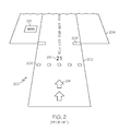
- a conventional displayed runway may include several visual markers 200, for example, a runway outline 202, an airport symbol 204, a threshold 206, a touchdown zone 208 (or aiming point), a runway identification 210, runway remaining signs 212, and unusable runway markers 214.
- visual markers 200 for example, a runway outline 202, an airport symbol 204, a threshold 206, a touchdown zone 208 (or aiming point), a runway identification 210, runway remaining signs 212, and unusable runway markers 214.
- the runway outline 202 around the edges of the runway provides delineation of runway of intended landing along with motion and location cues to the pilot when the range to the runway is not too long.
- the position, length, and width of the runway are stored in the runway database 110 for a plurality of runways.
- the size of the runway outline 202 is calculated.
- the super-sized intended airport symbol 204 is visible on the display screen at large distances from the runway. It emanates from the touchdown zone 208 and provides cues as to where the runway is, perspective cues to the runway, and the location of the touchdown zone.
- the dynamic sizing of the airport symbol 204 provides motion cues in all dimensions, i.e. up/down, left/right and forward motion flow including sense of ground closure.
- the size of the runway symbol 204 is determined by software based on the runway size, the altitude and attitude of the aircraft distance to the approaching runway. The symbol size change may not be linearly related to the distance to the runway. Generally, the size of the runway symbol 204 is about up to twice the runway length and about up to six times the width of the runway when close by.
- the runway symbol 204 may be twice the length but more than 10 times the width of the runway in order to facilitate the visual identification of the intended landing area on the display due to perspective view size reduction at distance.
- the runway symbol 204 may become six times of the runway width.
- the threshold 206 is typically marked with a series of boxes and indicates the start of the usable runway.
- the touchdown zone 208 (aiming point) is calculated from the runway database values gathered from the Aeronautical Information Publication and is visible on the display screen at large distances from the runway. It is the "point of reference” of the flight director (FD). The flight director is providing commands to "fly" the flight-path vector symbol to the touchdown zone.
- the touch down zone symbols include the rendered marking area, e.g., a filled rectangle, on the runway and the leading edge of the runway symbol box centered at the touch down zone.
- the runway identifier 210 is a number representing the runway, and is determined by the magnetic heading of the runway. For example, a runway having a magnetic heading of 210 has a runway identifier of 21, or the left runway of two runways having a magnetic heading of 080 would have a runway identifier of 08L.
- the runway remaining markers 212 simulate actual signs on the side of the runway that indicate the amount of runway ahead of the aircraft during landing, allowing the pilot to judge the rate of deceleration needed during roll out after touchdown.
- Additional visual markers may be displayed (not shown in FIG. 2 ), for example, an approach course leading up to the runway or a runway texture. Additionally, the visual markers 200 may be color coded.
- the system and method disclosed herein automatically updates the display for the pilot with information received in a NOTAM, supporting the pilot's ability to continue a modified flight path to the intended runway. While the NOTAM data described herein relates to a displaced threshold, the NOTAM data may comprise other information related to aircraft safety, including for example, weather, special traffic, restrictions, and airport updates.
- FIG. 3 is a flow chart that illustrates an exemplary embodiment of a process 300 suitable for use with a flight deck display system such as the display system 116.
- Process 300 represents one implementation of a method for displaying aircraft traffic information on an onboard display element of a host aircraft.
- the various tasks performed in connection with process 300 may be performed by software, hardware, firmware, or any combination thereof.
- the following description of process 300 may refer to elements mentioned above in connection with FIG. 3 .
- portions of process 300 may be performed by different elements of the described system, e.g., a processor, a display element, or a data communication component. It should be appreciated that process 300 may include any number of additional or alternative tasks, the tasks shown in FIG.
- process 300 need not be performed in the illustrated order, and process 300 may be incorporated into a more comprehensive procedure or process having additional functionality not described in detail herein. Moreover, one or more of the tasks shown in FIG. 3 could be omitted from an embodiment of the process 300 as long as the intended overall functionality remains intact.
- the flow chart of FIG. 3 includes receiving 302 a NOTAM message containing information of a displaced threshold.
- the message typically contains a distance of the displaced threshold from the original threshold.
- the NOTAM message is parsed 304 and stored 306 in a data base on-board the aircraft. If a manual input is not selected 308, the current position of the aircraft is retrieved 310 from the data sources 114, the flight management system determines 312 the arrival runway, and the data base is searched 314 for runway length and displaced threshold distance using the arrival runway identified in step 312.
- the stored NOTAM data is searched 318 for a displaced threshold distance and if found, the runway touchdown zone 208, threshold 206, runway identifier 210, and runway symbol 204 are adjusted 320.
- the touchdown zone 206 and distance remaining markers 212 are modified, for example, by moving the distance remaining markers 212.
- the touchdown zone and distance remaining markers are modified taking the displaced threshold distance into account.
- step 308 the flight management system selects 316 the arrival runway (per a programmed flight plan), and steps 314, 318, and 320 are performed (by omitting steps 310 and 312).
- the display of the displaced threshold may be made in one of several ways as depicted by the examples in FIGS. 4-10 .
- the display 116 is updated and an indication may be made to the pilot that the change is made using NOTAM data through symbology or in a particular color, or an annunciation or icon on the side of the runway markings, or by a status crew alerting system message.
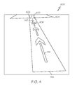
- a first exemplary embodiment of the display of the displaced threshold 406 shown in FIG. 4 includes arrows 414 (using typical SVS symbology) stretching from the actual end 416 of the runway 404 to the threshold 406.
- Each of the visual markers 400 including a runway outline 402, a runway symbol 404, a threshold 406, a touchdown zone 408 (or aiming point), a runway identification 410, and arrows 414 are repositioned with regard to the displaced threshold 406, and an annunciation is displayed to indicate the NOTAM in effect.
- the displaced threshold in SVS and 3D Advanced Motion Measurement (AMM) updated via NOTAM may be displayed using symbology different from that used for displaying displaced thresholds taken from database values.
- a second exemplary embodiment of FIG. 5 shows the arrows 514 encased in a note.
- a third exemplary embodiment of FIG. 6 has the original threshold 206 and runway identification 210 modified, for example, crossed out or deemphasized in some fashion, with the repositioned displaced threshold 606, runway identification 610, and touchdown zone 608 displayed. The runway outline 602 and runway symbol 604 are moved to coincide with the new touchdown zone 608.
- the displaced threshold 706 is indicated by the display, on one side or preferably on both sides of the runway, with arrows 722 and a line 724.
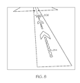
- the displaced threshold 806 in FIG. 8 is emphasized by arrows 814, being dashed to differentiate them from indicating a non-displaced threshold.
- the NOTAM information may be supplied in text format.
- "UPD DSPLCD THR RWY KPHX 7L NOTAM” indicates that an update has been issued of a displaced threshold at the Phoenix airport (sky harbor) runway 7L by NOTAM.
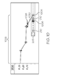
- FIG. 10 shows a combined top view and a side view of a displaced threshold 1006, the repositioned runway identifier 1010, and touchdown zone 1008, along with the original threshold 206 and runway identifier 210.
- the side view (profile) of the flight path 1026 for the aircraft 1028 is shown, with the last leg 1030 of the flight path 1026 ending at the touchdown zone 1008.
Applications Claiming Priority (1)
| Application Number | Priority Date | Filing Date | Title |
|---|---|---|---|
| US13/454,684 US9041560B2 (en) | 2012-04-24 | 2012-04-24 | System and method of displaying a runway temporarily displaced threshold and an aircraft landing aiming point |
Publications (2)
| Publication Number | Publication Date |
|---|---|
| EP2657923A2 true EP2657923A2 (de) | 2013-10-30 |
| EP2657923A3 EP2657923A3 (de) | 2014-03-05 |
Family
ID=48050533
Family Applications (1)
| Application Number | Title | Priority Date | Filing Date |
|---|---|---|---|
| EP13162816.6A Withdrawn EP2657923A3 (de) | 2012-04-24 | 2013-04-08 | System und Verfahren zum Anzeigen eines zeitweise verschobenen Landebahnschwellenwerts und Flugzeuglandungszielpunkt |
Country Status (2)
| Country | Link |
|---|---|
| US (1) | US9041560B2 (de) |
| EP (1) | EP2657923A3 (de) |
Cited By (8)
| Publication number | Priority date | Publication date | Assignee | Title |
|---|---|---|---|---|
| US9884690B2 (en) | 2016-05-03 | 2018-02-06 | Honeywell International Inc. | Methods and systems for conveying destination viability |
| EP3340208A1 (de) * | 2016-12-22 | 2018-06-27 | Thales | Verwaltung der nachrichten an flugpersonal |
| US10096253B2 (en) | 2015-11-30 | 2018-10-09 | Honeywell International Inc. | Methods and systems for presenting diversion destinations |
| US10109203B2 (en) | 2016-09-07 | 2018-10-23 | Honeywell International Inc. | Methods and systems for presenting en route diversion destinations |
| US10134289B2 (en) | 2016-02-18 | 2018-11-20 | Honeywell International Inc. | Methods and systems facilitating stabilized descent to a diversion airport |
| US10304344B2 (en) | 2016-02-09 | 2019-05-28 | Honeywell International Inc. | Methods and systems for safe landing at a diversion airport |
| CN112287526A (zh) * | 2020-10-15 | 2021-01-29 | 中国工程物理研究院总体工程研究所 | 一种跑道打击最优方案的设计方法 |
| EP4332943A1 (de) * | 2022-08-19 | 2024-03-06 | Honeywell International Inc. | Flugzeugsysteme und verfahren mit automatisierten landebahnzustandsinformationen |
Families Citing this family (22)
| Publication number | Priority date | Publication date | Assignee | Title |
|---|---|---|---|---|
| FR2983176B1 (fr) | 2011-11-29 | 2013-12-27 | Airbus Operations Sas | Dispositif de dialogue interactif entre un operateur d'un aeronef et un systeme de guidage dudit aeronef. |
| US20130179792A1 (en) * | 2011-12-29 | 2013-07-11 | Passur Aerospace, Inc. | System and Method for National Field Condition Reporting |
| FR3001066B1 (fr) | 2013-01-11 | 2015-02-27 | Airbus Operations Sas | Systeme d'assistance au guidage d'actions a realiser par un operateur sur un aeronef. |
| US9280904B2 (en) * | 2013-03-15 | 2016-03-08 | Airbus Operations (S.A.S.) | Methods, systems and computer readable media for arming aircraft runway approach guidance modes |
| US9567099B2 (en) | 2013-04-11 | 2017-02-14 | Airbus Operations (S.A.S.) | Aircraft flight management devices, systems, computer readable media and related methods |
| FR3016223B1 (fr) * | 2014-01-03 | 2017-03-10 | Airbus Operations Sas | Procede et dispositif de determination d'un profil de terrain lineaire le long d'une trajectoire laterale d'approche d'un aeroport. |
| FR3016222B1 (fr) | 2014-01-03 | 2016-02-05 | Airbus Operations Sas | Procede et dispositif de guidage vertical d'un aeronef lors d'une approche d'une piste d'atterrissage le long d'une trajectoire laterale d'approche. |
| US20150261829A1 (en) * | 2014-03-13 | 2015-09-17 | Honeywell International Inc. | System and method for intelligently mining information and briefing an aircrew on conditions outside the aircraft |
| US10529240B2 (en) | 2014-03-13 | 2020-01-07 | Honeywell International Inc. | System and method for intelligently mining information and briefing an aircrew on conditions outside the aircraft |
| DE102014104572B4 (de) * | 2014-04-01 | 2017-11-02 | Deutsches Zentrum für Luft- und Raumfahrt e.V. | Geschwindigkeitsanzeige |
| EP2947637B1 (de) * | 2014-05-23 | 2018-09-26 | The Boeing Company | Verfahren zur hochgenauen Vorhersage einer mittels der Aircraft Intent Description Language (AIDL) beschriebenen Abstiegstrajektorie |
| US9399524B2 (en) | 2014-10-21 | 2016-07-26 | Honeywell International Inc. | System and method for displaying runway landing information |
| US20160351058A1 (en) * | 2015-05-29 | 2016-12-01 | Gulfstream Aerospace Corporation | Systems and methods for aircraft approach selection |
| US9646501B2 (en) | 2015-07-14 | 2017-05-09 | Honeywell International Inc. | System and method for integrating temporal data into flight management systems |
| US9573698B1 (en) | 2015-08-06 | 2017-02-21 | Honeywell International Inc. | Flight deck display systems and methods for generating cockpit displays including dynamically-adjusted usable runway length symbology |
| US9672749B1 (en) | 2016-04-08 | 2017-06-06 | Honeywell International Inc. | System and method for updating ILS category and decision height |
| US20170310749A1 (en) * | 2016-04-25 | 2017-10-26 | Honeywell International Inc. | Methods and apparatus for flight briefing data synchronization |
| US10607494B2 (en) * | 2017-10-05 | 2020-03-31 | 3764729 Canada Inc. | Aircraft approach chart |
| CN111667723A (zh) * | 2020-06-10 | 2020-09-15 | 民航数据通信有限责任公司 | 一种数字化航行通告控制方法及装置 |
| US11817000B2 (en) * | 2020-12-10 | 2023-11-14 | Rockwell Collins, Inc. | System and method to reduce runway occupancy time using pseudo threshold |
| EP4012686A1 (de) * | 2020-12-10 | 2022-06-15 | Rockwell Collins, Inc. | System und verfahren zur verringerung der belegungszeit von start- und landebahnen mittels pseudoschwellen |
| US20230026834A1 (en) * | 2021-07-20 | 2023-01-26 | Honeywell International Inc. | Systems and methods for correlating a notice to airmen (notam) with a chart on an avionic display in a cockpit of an aircraft |
Citations (1)
| Publication number | Priority date | Publication date | Assignee | Title |
|---|---|---|---|---|
| US20080109160A1 (en) * | 2006-11-07 | 2008-05-08 | Thales | Device for assisting in the navigation of an aircraft in an airport zone |
Family Cites Families (18)
| Publication number | Priority date | Publication date | Assignee | Title |
|---|---|---|---|---|
| JP2710564B2 (ja) | 1994-09-29 | 1998-02-10 | 日本電気ソフトウェア株式会社 | ノータム電文処理システム |
| JPH11353600A (ja) | 1998-06-09 | 1999-12-24 | Nec Corp | 航空交通情報グラフィック表示装置および航空交通情報グラフィック表示方法 |
| US7769501B2 (en) | 2004-06-23 | 2010-08-03 | The Boeing Company | User-configurable electronic flight bag |
| US7908078B2 (en) | 2005-10-13 | 2011-03-15 | Honeywell International Inc. | Perspective-view visual runway awareness and advisory display |
| FR2897712B1 (fr) | 2006-02-20 | 2008-04-04 | Airbus France Sas | Dispositif d'aide au pilotage d'un aeronef lors d'une phase d'approche en vue d'un atterrissage. |
| US7908082B2 (en) * | 2007-05-04 | 2011-03-15 | The Boeing Company | Methods and systems for displaying airport moving map information |
| FR2935179B1 (fr) * | 2008-08-20 | 2010-12-03 | Airbus France | Procede et dispositif d'aide au controle des systemes embarques dans un aeronef |
| US7965223B1 (en) | 2009-02-03 | 2011-06-21 | Rockwell Collins, Inc. | Forward-looking radar system, module, and method for generating and/or presenting airport surface traffic information |
| US8209122B2 (en) | 2009-03-27 | 2012-06-26 | Honeywell International Inc. | System and method for rendering visible features of a target location on a synthetic flight display |
| US8200378B1 (en) * | 2009-09-30 | 2012-06-12 | Rockwell Collins, Inc. | System, module, and method for presenting NOTAM information on an aircraft display unit |
| US8060262B2 (en) | 2009-10-30 | 2011-11-15 | Honeywell International Inc. | Airport lighting aid simulation system |
| US8456328B2 (en) | 2010-02-17 | 2013-06-04 | Honeywell International Inc. | System and method for informing an aircraft operator about a temporary flight restriction in perspective view |
| EP2559017A2 (de) | 2010-04-12 | 2013-02-20 | Flight Focus Pte. Ltd. | Bewegliche kartenanzeige |
| US20110264313A1 (en) | 2010-04-22 | 2011-10-27 | Honeywell International Inc. | Flight planning with digital notam |
| US8462019B1 (en) | 2010-09-17 | 2013-06-11 | Rockwell Collins, Inc. | Position-dependent system, apparatus, and method for generating runway visual aids presented on an aircraft display unit |
| US9410819B2 (en) * | 2011-08-02 | 2016-08-09 | The Boeing Company | Management system for aeronautical information |
| US8760319B2 (en) * | 2011-11-15 | 2014-06-24 | Honeywell International Inc. | Aircraft monitoring with improved situational awareness |
| US8761971B2 (en) * | 2012-01-11 | 2014-06-24 | The Boeing Company | Auto-flight system pilot interface |
-
2012
- 2012-04-24 US US13/454,684 patent/US9041560B2/en not_active Expired - Fee Related
-
2013
- 2013-04-08 EP EP13162816.6A patent/EP2657923A3/de not_active Withdrawn
Patent Citations (1)
| Publication number | Priority date | Publication date | Assignee | Title |
|---|---|---|---|---|
| US20080109160A1 (en) * | 2006-11-07 | 2008-05-08 | Thales | Device for assisting in the navigation of an aircraft in an airport zone |
Non-Patent Citations (1)
| Title |
|---|
| SPIE, PO BOX 10 BELLINGHAM WA 98227-0010 USA, 16 March 2008 (2008-03-16), XP040437225 * |
Cited By (11)
| Publication number | Priority date | Publication date | Assignee | Title |
|---|---|---|---|---|
| US10096253B2 (en) | 2015-11-30 | 2018-10-09 | Honeywell International Inc. | Methods and systems for presenting diversion destinations |
| US10304344B2 (en) | 2016-02-09 | 2019-05-28 | Honeywell International Inc. | Methods and systems for safe landing at a diversion airport |
| US10134289B2 (en) | 2016-02-18 | 2018-11-20 | Honeywell International Inc. | Methods and systems facilitating stabilized descent to a diversion airport |
| US9884690B2 (en) | 2016-05-03 | 2018-02-06 | Honeywell International Inc. | Methods and systems for conveying destination viability |
| EP3242280A3 (de) * | 2016-05-03 | 2018-03-14 | Honeywell International Inc. | Verfahren und systeme zur beförderungszieldurchführbarkeit |
| US10109203B2 (en) | 2016-09-07 | 2018-10-23 | Honeywell International Inc. | Methods and systems for presenting en route diversion destinations |
| EP3340208A1 (de) * | 2016-12-22 | 2018-06-27 | Thales | Verwaltung der nachrichten an flugpersonal |
| FR3061342A1 (fr) * | 2016-12-22 | 2018-06-29 | Thales | Gestion des messages aux navigants aeriens |
| US10482774B2 (en) | 2016-12-22 | 2019-11-19 | Thales | Management of notices to airmen |
| CN112287526A (zh) * | 2020-10-15 | 2021-01-29 | 中国工程物理研究院总体工程研究所 | 一种跑道打击最优方案的设计方法 |
| EP4332943A1 (de) * | 2022-08-19 | 2024-03-06 | Honeywell International Inc. | Flugzeugsysteme und verfahren mit automatisierten landebahnzustandsinformationen |
Also Published As
| Publication number | Publication date |
|---|---|
| US20130278444A1 (en) | 2013-10-24 |
| EP2657923A3 (de) | 2014-03-05 |
| US9041560B2 (en) | 2015-05-26 |
Similar Documents
| Publication | Publication Date | Title |
|---|---|---|
| US9041560B2 (en) | System and method of displaying a runway temporarily displaced threshold and an aircraft landing aiming point | |
| US9733103B2 (en) | System and display element for displaying waypoint markers with integrated altitude constraint information | |
| US9478140B2 (en) | System and method for displaying traffic and associated alerts on a three-dimensional airport moving map display | |
| EP3321634B1 (de) | System und verfahren zur anzeige von landebahnüberschreitungsinformationen | |
| US7952493B2 (en) | System and method for rendering a primary flight display having an attitude frame element | |
| EP2775469B1 (de) | System und Verfahren zur Verwaltung eines Intervalls zwischen Flugzeugen | |
| EP2779140B1 (de) | System und Verfahren zur Alarmierung des Flugzeugpersonals vor Schwellenhöhen | |
| US9354078B2 (en) | Methods and systems for indicating whether an aircraft is within distance and altitude criteria for an IFR procedure turn | |
| US20100023187A1 (en) | System and method for displaying constraint information on a graphical aircraft instrument tape element | |
| EP2199746A2 (de) | System und Verfahren zur Bildwiedergabe von Flugzeuginformationen auf einer Anzeige zur vertikalen Situation | |
| EP3012590A1 (de) | System und verfahren zur anzeige von landebahnanfluginformationen | |
| EP2919219B1 (de) | System und Verfahren zur Identifizierung der Rollbahnposition während des Abflugs auf einer Rollbahneinmündung | |
| US20100148990A1 (en) | System and method for selectively displaying terminal procedure data | |
| EP3023741B1 (de) | System und verfahren zur exozentrischen anzeige von integrierter navigation | |
| EP2762837A2 (de) | System und Verfahren zur Geländehöhenanzeige auf einem Flugzeugbildschirm | |
| EP2913813B1 (de) | System und Verfahren zur Landebahnauswahl mittels Bewertung | |
| EP2645065A2 (de) | System und Verfahren zum Anzeigen der verbleibenden Landebahndistanz bei einer kurzen Landung (LAHSO) | |
| EP2801964A1 (de) | System und Verfahren zur Anzeige der Rate-of-climb auf einem Avionik-Vertikalgeschwindigkeitsanzeiger |
Legal Events
| Date | Code | Title | Description |
|---|---|---|---|
| PUAI | Public reference made under article 153(3) epc to a published international application that has entered the european phase |
Free format text: ORIGINAL CODE: 0009012 |
|
| 17P | Request for examination filed |
Effective date: 20130408 |
|
| AK | Designated contracting states |
Kind code of ref document: A2 Designated state(s): AL AT BE BG CH CY CZ DE DK EE ES FI FR GB GR HR HU IE IS IT LI LT LU LV MC MK MT NL NO PL PT RO RS SE SI SK SM TR |
|
| AX | Request for extension of the european patent |
Extension state: BA ME |
|
| PUAL | Search report despatched |
Free format text: ORIGINAL CODE: 0009013 |
|
| AK | Designated contracting states |
Kind code of ref document: A3 Designated state(s): AL AT BE BG CH CY CZ DE DK EE ES FI FR GB GR HR HU IE IS IT LI LT LU LV MC MK MT NL NO PL PT RO RS SE SI SK SM TR |
|
| AX | Request for extension of the european patent |
Extension state: BA ME |
|
| RIC1 | Information provided on ipc code assigned before grant |
Ipc: G08G 5/00 20060101AFI20140129BHEP Ipc: G08G 5/02 20060101ALI20140129BHEP Ipc: G01C 23/00 20060101ALI20140129BHEP |
|
| 17Q | First examination report despatched |
Effective date: 20140313 |
|
| RAP1 | Party data changed (applicant data changed or rights of an application transferred) |
Owner name: HONEYWELL INTERNATIONAL INC. |
|
| APBK | Appeal reference recorded |
Free format text: ORIGINAL CODE: EPIDOSNREFNE |
|
| APBN | Date of receipt of notice of appeal recorded |
Free format text: ORIGINAL CODE: EPIDOSNNOA2E |
|
| APAF | Appeal reference modified |
Free format text: ORIGINAL CODE: EPIDOSCREFNE |
|
| APBT | Appeal procedure closed |
Free format text: ORIGINAL CODE: EPIDOSNNOA9E |
|
| STAA | Information on the status of an ep patent application or granted ep patent |
Free format text: STATUS: THE APPLICATION HAS BEEN WITHDRAWN |
|
| 18W | Application withdrawn |
Effective date: 20180214 |