EP2657694A2 - Tool and method for manipulating a transducer assembly - Google Patents
Tool and method for manipulating a transducer assembly Download PDFInfo
- Publication number
- EP2657694A2 EP2657694A2 EP13150371.6A EP13150371A EP2657694A2 EP 2657694 A2 EP2657694 A2 EP 2657694A2 EP 13150371 A EP13150371 A EP 13150371A EP 2657694 A2 EP2657694 A2 EP 2657694A2
- Authority
- EP
- European Patent Office
- Prior art keywords
- transducer assembly
- tool
- transducer
- guide member
- tool according
- Prior art date
- Legal status (The legal status is an assumption and is not a legal conclusion. Google has not performed a legal analysis and makes no representation as to the accuracy of the status listed.)
- Withdrawn
Links
Images
Classifications
-
- G—PHYSICS
- G01—MEASURING; TESTING
- G01N—INVESTIGATING OR ANALYSING MATERIALS BY DETERMINING THEIR CHEMICAL OR PHYSICAL PROPERTIES
- G01N29/00—Investigating or analysing materials by the use of ultrasonic, sonic or infrasonic waves; Visualisation of the interior of objects by transmitting ultrasonic or sonic waves through the object
- G01N29/22—Details, e.g. general constructional or apparatus details
- G01N29/225—Supports, positioning or alignment in moving situation
- G01N29/226—Handheld or portable devices
-
- G—PHYSICS
- G01—MEASURING; TESTING
- G01N—INVESTIGATING OR ANALYSING MATERIALS BY DETERMINING THEIR CHEMICAL OR PHYSICAL PROPERTIES
- G01N29/00—Investigating or analysing materials by the use of ultrasonic, sonic or infrasonic waves; Visualisation of the interior of objects by transmitting ultrasonic or sonic waves through the object
- G01N29/22—Details, e.g. general constructional or apparatus details
- G01N29/26—Arrangements for orientation or scanning by relative movement of the head and the sensor
- G01N29/265—Arrangements for orientation or scanning by relative movement of the head and the sensor by moving the sensor relative to a stationary material
-
- G—PHYSICS
- G01—MEASURING; TESTING
- G01N—INVESTIGATING OR ANALYSING MATERIALS BY DETERMINING THEIR CHEMICAL OR PHYSICAL PROPERTIES
- G01N2291/00—Indexing codes associated with group G01N29/00
- G01N2291/26—Scanned objects
- G01N2291/269—Various geometry objects
- G01N2291/2694—Wings or other aircraft parts
Definitions
- the transducer assembly may be an ultrasound transducer assembly.
Landscapes
- Physics & Mathematics (AREA)
- Health & Medical Sciences (AREA)
- Life Sciences & Earth Sciences (AREA)
- Chemical & Material Sciences (AREA)
- Analytical Chemistry (AREA)
- Biochemistry (AREA)
- General Health & Medical Sciences (AREA)
- General Physics & Mathematics (AREA)
- Immunology (AREA)
- Pathology (AREA)
- Investigating Or Analyzing Materials By The Use Of Ultrasonic Waves (AREA)
Abstract
Description
- The present invention relates to a tool suitable for manipulating a transducer assembly and to a method of manipulating a transducer assembly.
- Non-visible areas of materials, such as the interiors of components, welds and composite materials can be analysed using ultrasonic testing. This type of non-destructive testing utilises the reflection of sound waves to detect faults and features which would otherwise be very difficult to detect without destroying the component in the process. Ultrasonic testing is a common technique in the aerospace sector to test the integrity of materials at manufacture and components during service.
- If a component within an assembly, such as an aircraft, is to be tested using non-destructive testing it is in some cases necessary to partially disassemble the assembly to access a specific part of the component. The location of the component and the manner in which it is tested may determine the degree of disassembly required. For example, an aircraft forward engine pylon mounting is a well known component that may be analysed for damage using an ultrasonic testing scanner. Such a mounting generally consists of a number of plate-like lugs positioned in a parallel side by side arrangement, each lug having a hole for receiving a common attachment link by which the engine pylon is coupled to the mounting. In testing, an ultrasound transducer is moved across a major face of one or more of the lugs to detect cracks and the like. However, in order to access a major face of the forward engine pylon mounting it is necessary to remove the engine and pylon, which has an adverse effect on servicing time and complexity.
- The present application relates to a tool for manipulating a transducer assembly. The tool had a shaft to space the transducer assembly from a grasping end. The tool rotatably mounts the transducer assembly so that the transducer assembly can transmissively coupled to and follow an arcuate scanning path. The tool includes a guide member for following an edge of a component to be tested.
- A first aspect of the invention provides a tool for manipulating a transducer assembly, the transducer assembly having an emission face from which in use an analysis signal is emitted. The tool may comprise an elongate shaft coupled to a transducer receiving portion. The transducer receiving portion may be arranged to be rotatably coupled to the transducer assembly. The tool may include a guide member. The guide member may be arranged in use to project beyond the emission face of the transducer assembly. Thus, a tool according to embodiments of the present invention may be used to manipulate a transducer assembly along an arcuate scanning surface which is difficult to access by hand. The transducer assembly may pivot about the tool to remain transmissively coupled to the scanning surface as the tool is moved. The guide member can be used to follow an edge, which may increase scan accuracy and repeatability.
- The guide member may be arranged to project beyond the emission face when the transducer assembly is at a plurality of different angular positions. This may improve the utility of the tool as different arcs and gradients may be scanned.
- The transducer receiving portion may comprise first and second arms arranged to be rotatably coupled to respective opposite sides of the transducer assembly.
- The arms may be generally planar and positioned so as to be orthogonal to the rotational axis of the transducer. This may provide a laterally compact tool.
- The tool may include a shoe arranged to be transmissively coupled to the transducer so as to form the transducer assembly. The shoe may be arranged to be rotatably coupled to the transducer receiving portion of the tool such that the shoe may pivot about the rotational axis.
- The emission face may have a concave outer profile.
- The tool may be in combination with the transducer assembly.
- The transducer assembly may be an ultrasound transducer assembly. The analysis signal may be ultrasound.
- The tool may be arranged to be manipulated by hand; for example, a distal portion of the shaft may be provided with, or may define, a handle.
- A further aspect of the invention provides use of the tool according to the first aspect as a manipulator for a transducer assembly during non-destructive testing of a component.
- A further aspect of the invention provides a method of manipulating a transducer assembly. The method may comprise providing a tool according to the first aspect. The method may comprise positioning the tool such that the guide member is adjacent or in contact with a guide surface of the component and the transducer assembly is transmissively coupled to a scanning surface of the component. The method may comprise moving the transducer assembly along the scanning surface such that the guide member remains adjacent or in contact with the guide surface.
- The method may include moving the transducer of the transducer assembly to a different position within the shoe of the transducer assembly.
- The method may include rotating the tool about its longitudinal axis L by 180° and positioning the tool such that the guide member is adjacent or in contact with a second guide surface of the component and the transducer assembly is transmissively coupled to a scanning surface of the component.
- The scanning surface may be arcuate.
- The scanning surface may be positioned within a narrow recess.
- The transducer assembly may be an ultrasound transducer assembly.
- Embodiments of the invention will now be described with reference to the accompanying drawings, in which:
-
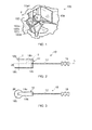
Figure 1 is a diagram showing a known aircraft forward engine pylon mounting; -
Figure 2 is a diagram showing a plan view of a tool according to an embodiment of the present invention; -
Figure 3 is a diagram showing a side view of the tool ofFigure 2 ; -
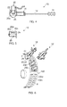
Figure 4 is a diagram showing a side view of the tool ofFigure 2 with a transducer assembly mounted thereto; -
Figure 5 is a diagram showing a front view of the tool ofFigure 4 ; and -
Figure 6 is a diagram illustrating a method of using the tool. -
Figure 1 shows part of anaircraft 100 including a known forward engine pylon mounting/fitting which will be referred to as a "pylon mounting" 102. Thepylon mounting 102 is attached to thefront spar 104 of theaircraft 100 and consists of four plate-like lugs 102a - 102d positioned in a parallel, side by side arrangement. Eachlug 102a - 102d has alateral hole 104d for receiving a common attachment link (not shown) by which the engine pylon (not shown) may be coupled to themounting 102. - Over time, cracks or other damage may occur within the
pylon mounting 102 and it is desirable to check for damage by non-destructive testing; for example, the condition of themounting lugs 102a - 102d can be analysed using ultrasonic testing. - It is known to move an ultrasound transducer across a major face M of the
mounting 102. However, this requires removal of the engine pylon. The present inventor has discovered that eachlug 102a - 102d may instead be scanned along an edge surface (seeFigure 6 ) to check for damage using ultrasonic testing. One problem however is that the upper and/or lower regions of the edge surfaces are difficult to access due to adjacent components. This is particularly problematic on the A340, A500 and A600 aircraft produced by Airbus, although the same is true for many aircraft. Similar problems exist when trying to scan a surface which is disposed within a narrow recess i.e. a recess which is sized and/or configured such that it is difficult for a user to hold a transducer in their hand and move it across the scanning surface. Such a recess may be formed by components which are adjacent the scanning surface. - Referring to
Figures 2 to 5 , atool 10 according to an embodiment of the present invention is shown. Thetool 10 is arranged to enable a user to move an ultrasound or other non-destructive testing transducer along a surface which is disposed within a narrow recess. The effective length of thetool 10, i.e. the distance from the transducer to the grasping end, may be any suitable length; for example, at least 25mm, 50mm, 75mm, 100mm, 125mm or 150mm and/or less than 1m, 750mm, 500mm, 250mm, 150mm or 100mm. - The
tool 10 includes anelongate shaft 12 having a first end attached to atransducer receiving portion 14 and a second end which may optionally be provided with ahandle 16. Theshaft 12 may be between 10mm and 150mm in length and preferably between 25mm and 75mm. The shaft may be formed of any suitable material, such as spring steel and may have any suitable shape and configuration. - In the illustrated embodiment the
transducer 22 is transmissively coupled to ashoe 20 such that ultrasound may be transmitted to and received from a target feature via the shoe. Thetransducer 22, with or without ashoe 20, will for simplicity be referred to herein as a "transducer assembly". Thetool 10 may be used with anysuitable transducer assembly - In the illustrated embodiment the
transducer 20 is an8mm x 8mm 16 element probe such as one marketed my Olympus NDT Limited under the part number U8330589. - The shoe is formed from a plastics material having, in this embodiment, a sound velocity of 2330 meters per second and, as shown in
Figure 5 , includes arecess 20a which is wider than thetransducer 22 and thus can receive thetransducer 22 at various lateral positions. Locking elements 20b, 20c, such as screws which may be advanced into therecess 20a, are provided to lock the position of thetransducer 22 within theshoe 20. - The
transducer receiving portion 14 is arranged to be rotationally coupled to anultrasound transducer 22. In the illustrated embodiment thetransducer receiving portion 14 comprises a pair ofelongate arms shaft 12. Thearms arms shaft 12 so as to define a receiving space S between them. The receiving space S is sized to receive thetransducer assembly - A
rotational coupling element arm coupling elements transducer assembly holes shoe 20 in which theultrasound transducer 22 is situated. However, in other embodiments thecoupling elements transducer assembly coupling elements transducer 22. - In the illustrated embodiment the
arms flat arms compact tool 10 which is useful when scanning surfaces which are difficult to access; for example, a surface within a narrow recess. - The
transducer assembly emission surface 20a". Theemission surface 20a may be profiled to conform to the surface it is arranged to scan. Thus, theemission surface 20a of atransducer assembly - The
tool 10 also includes aguide member 24 which projects beyond the "emission surface 20a". Theguide member 24 is positionally fixed with respect to thetransducer assembly transducer assembly guide member 24 is arranged such that in use it does not overlap theemission surface 20a i.e. theguide member 24 is adjacent or spaced from theemission surface 20a along axis T, meaning that theentire emission surface 20a may be coupled to a scanning surface while theguide member 24 is adjacent or in contact with a guide surface. - In the illustrated embodiment the
guide member 24 is a generally disc shaped continuation of thearm 14b, positioned such that its centre is generally coaxial with the axis T about which thetransducer assembly guide member 24 extends radially such that its circumferential edge projects beyond theemission surface 20a. Thus, theguide member 24 functions throughout a 270° arc of rotation of thetransducer assembly tool 10 be rotated about its longitudinal axis L by 180° to change from guiding thetransducer assembly tool 10. - In other embodiments the
guide member 24 may take any suitable form in which it projects beyond theemission surface 20a when thetransducer assembly guide member 24 may be generally "T" shaped and side on such that side projections of the "T" extend in a generally orthogonal manner with respect to both the longitudinal axis L of theshaft 12 and the rotational axis T of thetransducer assembly guide member 24 may be at least 25%, 40% or 50% of the width of the receiving space S, the width being parallel to the axis T. -
Figure 5 illustrates a method of scanning a pylon mounting 102 using atool 10 according to an embodiment of the invention. As shown, thetool 10 is positioned such that theguide member 24 is against a guide surface of afirst lug 102c of the pylon mounting 102 and, with thetransducer 22 positioned and locked within theshoe 20 such that it is at its closest position to theguide member 24, thetransducer assembly lug 102c. - The
transducer 22 may be positioned and locked within theshoe 20 such that it is at its furthest position from theguide member 24 and moved along a scanning path P2 at the opposite side of the edge of thelug 102c. - As shown, the tool may be rotated about its longitudinal axis L by 180°, shown as 10', such that the edge of
lug 102d may be scanned in a similar manner. - Thus, a tool according to embodiments of the present invention may be used to manipulate a transducer assembly along an arcuate scanning surface which is difficult to access by hand. The transducer assembly may pivot about the tool to remain transmissively coupled to the scanning surface as the tool is moved. The guide member can be used to follow an edge to increase the accuracy and repeatability of the scanning path, which may otherwise deteriorate with distance from the user.
- Although the invention has been described above with reference to one or more preferred embodiments, it will be appreciated that various changes or modifications may be made without departing from the scope of the invention as defined in the appended claims.
Claims (18)
- A tool for manipulating a transducer assembly, the transducer assembly having an emission face from which in use an analysis signal is emitted, the tool comprising an elongate shaft coupled to a transducer receiving portion, the transducer receiving portion being arranged to be rotatably coupled to the transducer assembly, and a guide member, the guide member being arranged in use to project beyond the emission face of the transducer assembly.
- A tool according to claim 1, wherein the guide member is arranged to project beyond the emission face when the transducer assembly is at a plurality of different angular positions.
- A tool according to any preceding claim, wherein the transducer receiving portion comprises first and second arms arranged to be rotatably coupled to respective opposite sides of the transducer assembly.
- A tool according to any preceding claim, wherein the arms are generally planar and positioned so as to be orthogonal to the rotational axis of the transducer.
- A tool according to any preceding claim including a shoe arranged to be transmissively coupled to the transducer so as to form the transducer assembly, the shoe being arranged to be rotatably coupled to the transducer receiving portion of the tool such that the shoe may pivot about the rotational axis.
- A tool according to any preceding claim, wherein the emission face has concave outer profile.
- A tool according to any preceding claim in combination with the transducer assembly.
- A tool according to any preceding claim, wherein the transducer assembly is an ultrasound transducer assembly and the analysis signal is ultrasound.
- A tool according to any preceding claim, including a handle.
- Use of the tool according to any preceding claim as a manipulator for a transducer assembly during non-destructive testing of a component.
- A method of manipulating a transducer assembly, the method comprising:providing a tool according to any preceding claim;positioning the tool such that the guide member is adjacent or in contact with a guide surface of the component and the transducer assembly is transmissively coupled to a scanning surface of the component; andmoving the transducer assembly along the scanning surface such that the guide member remains adjacent or in contact with the guide surface.
- A method according to claim 11, including moving the transducer of the transducer assembly to a different position within the shoe of the transducer assembly.
- A method according to any preceding claim, including rotating the tool about its longitudinal axis L by 180° and positioning the tool such that the guide member is adjacent or in contact with a second guide surface of the component and the transducer assembly is transmissively coupled to a scanning surface of the component.
- A method according to any preceding claim, wherein the scanning surface is arcuate.
- A method according to any preceding claim, wherein the scanning surface is positioned within a narrow recess.
- A method according to any preceding claim, wherein the transducer assembly is an ultrasound transducer assembly.
- A tool substantially a herein described with reference to Figures 2 to 5.
- A use and method substantially a herein described with reference to Figure 6.
Applications Claiming Priority (1)
| Application Number | Priority Date | Filing Date | Title |
|---|---|---|---|
| GBGB1200274.7A GB201200274D0 (en) | 2012-01-09 | 2012-01-09 | Tool and method for manipulating a transducer assembly |
Publications (2)
| Publication Number | Publication Date |
|---|---|
| EP2657694A2 true EP2657694A2 (en) | 2013-10-30 |
| EP2657694A3 EP2657694A3 (en) | 2014-04-02 |
Family
ID=45788645
Family Applications (1)
| Application Number | Title | Priority Date | Filing Date |
|---|---|---|---|
| EP13150371.6A Withdrawn EP2657694A3 (en) | 2012-01-09 | 2013-01-07 | Tool and method for manipulating a transducer assembly |
Country Status (5)
| Country | Link |
|---|---|
| US (1) | US9261489B2 (en) |
| EP (1) | EP2657694A3 (en) |
| JP (1) | JP2013142697A (en) |
| CN (1) | CN103196999B (en) |
| GB (1) | GB201200274D0 (en) |
Families Citing this family (2)
| Publication number | Priority date | Publication date | Assignee | Title |
|---|---|---|---|---|
| US9658193B2 (en) * | 2013-09-11 | 2017-05-23 | General Electric Company | Rolling phased array ultrasonic scanner |
| EP3290894B1 (en) * | 2016-09-06 | 2022-12-07 | General Electric Technology GmbH | Inspection probe |
Family Cites Families (42)
| Publication number | Priority date | Publication date | Assignee | Title |
|---|---|---|---|---|
| US2666862A (en) * | 1951-04-11 | 1954-01-19 | Branson Instr | Rail flaw detection device |
| US2678559A (en) * | 1951-12-29 | 1954-05-18 | Sperry Prod Inc | Ultrasonic rail test device |
| US2824979A (en) * | 1955-12-19 | 1958-02-25 | Welding Service Inc | Ultrasonic fissure detector |
| LU38025A1 (en) * | 1958-12-10 | |||
| US3732444A (en) * | 1969-06-12 | 1973-05-08 | Rockwell International Corp | Tubular transducer and dry couplant therefor |
| US3585579A (en) * | 1969-07-09 | 1971-06-15 | Westinghouse Electric Corp | Side looking sonar transducer |
| US4027528A (en) * | 1975-12-15 | 1977-06-07 | Tyree Bill D | Apparatus for ultrasonic inspection of ferromagnetic materials |
| US4229978A (en) * | 1978-10-02 | 1980-10-28 | Dapco Industries, Inc. | System for selectably pulsing ultrasonic transducers in a test apparatus |
| JPS5713352A (en) * | 1980-06-30 | 1982-01-23 | Suzukou Shoji Kk | Probe holder for ultrasonic flaw detector |
| US4453409A (en) * | 1981-08-07 | 1984-06-12 | General Electric Company | Ultrasonic sector scanner utilizing rotating transducer |
| US4487071A (en) * | 1982-09-22 | 1984-12-11 | Dapco Industries, Inc. | Flaw detection system for railroad rails and the like |
| JPS5989261U (en) * | 1982-12-09 | 1984-06-16 | 株式会社トキメック | Ultrasonic probe holding mechanism |
| JPS6394153A (en) * | 1986-10-08 | 1988-04-25 | Furukawa Electric Co Ltd:The | Ultrasonic flaw detecting method |
| US4807476A (en) * | 1986-12-22 | 1989-02-28 | The Boeing Company | Variable angle transducer system and apparatus for pulse echo inspection of laminated parts through a full radial arc |
| US4898034A (en) * | 1988-08-23 | 1990-02-06 | The United States Of America As Represented By The Department Of Energy | High temperature ultrasonic testing of materials for internal flaws |
| US5343750A (en) * | 1991-11-25 | 1994-09-06 | General Electric Company | Manual ultrasonic scanner for complex surfaces |
| US5404755A (en) * | 1992-04-10 | 1995-04-11 | Olson Engineering, Inc. | Scanning apparatus and method for non-destructive materials evaluation and mapping through use of acoustic waves |
| US5419196A (en) * | 1993-03-19 | 1995-05-30 | Pandrol Jackson Technologies, Inc. | Ultrasonic side-looker for rail head flaw detection |
| US5535628A (en) * | 1994-11-14 | 1996-07-16 | Rohrback Cosasco Systems, Inc. | Ultrasonic scanner head and method |
| US5576492A (en) | 1995-01-26 | 1996-11-19 | United Technologies Corporation | Mechanical contour follower |
| US6055862A (en) * | 1996-06-10 | 2000-05-02 | Herzog Services, Inc. | Method of and an apparatus for detecting, identifying and recording the location of defects in a railway rail |
| US6248072B1 (en) * | 1997-09-19 | 2001-06-19 | John M. Murkin | Hand controlled scanning device |
| JPH11142379A (en) * | 1997-11-10 | 1999-05-28 | Ishikawajima Harima Heavy Ind Co Ltd | Ultrasonic probe scanning holder |
| JP2001056318A (en) * | 1999-08-20 | 2001-02-27 | Nippon Kogyo Kensa Kk | Flaw detection method of pipe by ultrasonic waves and ultrasonic flaw detector |
| US6276209B1 (en) * | 1999-09-30 | 2001-08-21 | Perceptron, Inc. | System and method of assessing the structural properties of wooden members using ultrasound |
| US6536553B1 (en) * | 2000-04-25 | 2003-03-25 | The United States Of America As Represented By The Secretary Of The Army | Method and apparatus using acoustic sensor for sub-surface object detection and visualization |
| US6571636B1 (en) * | 2000-09-14 | 2003-06-03 | Cf&I Steel, L.P. | Wheel-type transmit/receive ultrasonic inspection device with constant length internal liquid soundpath |
| US6871560B2 (en) * | 2001-02-15 | 2005-03-29 | Ucar Carbon Company Inc. | Electrode inspection system |
| US6688178B1 (en) * | 2001-03-02 | 2004-02-10 | Materials Systems, Inc. | Roller transducer apparatus |
| US7054762B2 (en) * | 2002-08-29 | 2006-05-30 | Dapco Industries Inc. | Method and system for analysis of ultrasonic reflections in real time |
| JP2004191225A (en) * | 2002-12-12 | 2004-07-08 | Ishikawajima Harima Heavy Ind Co Ltd | Pipe inspection device |
| US7174788B2 (en) | 2003-12-15 | 2007-02-13 | General Electric Company | Methods and apparatus for rotary machinery inspection |
| US7213459B2 (en) * | 2004-03-24 | 2007-05-08 | General Electric Company | High speed inspection system and method |
| FR2871567B1 (en) * | 2004-06-11 | 2006-11-24 | Snecma Moteurs Sa | NON-DESTRUCTIVE CONTROL INSTALLATION OF A WORKPIECE |
| DE102004051020A1 (en) * | 2004-10-20 | 2006-05-04 | Sms Demag Ag | Method, apparatus and circuit for detecting surface defects such as cracks, eruptions and the like on a roll of a rolling mill |
| WO2007017781A2 (en) * | 2005-08-05 | 2007-02-15 | Koninklijke Philips Electronics, N.V. | Curved 2-d array ultrasound transducer and method for volumetric imaging |
| DE102007039598B4 (en) * | 2006-09-05 | 2010-07-22 | DENSO CORPORATION, Kariya-shi | Ultrasonic sensor and obstacle detector device |
| JP4474395B2 (en) * | 2006-09-29 | 2010-06-02 | 株式会社日立製作所 | Turbine fork ultrasonic flaw detector and method |
| US7669477B2 (en) * | 2006-12-22 | 2010-03-02 | The Boeing Company | Ultrasonic probe for hollow fuse pin inspection |
| US20080236286A1 (en) * | 2007-03-29 | 2008-10-02 | Clive Chemo Lam | Non-destructive tubular testing |
| EP2437053A1 (en) * | 2009-05-28 | 2012-04-04 | Central Research Institute of Electric Power Industry | Scanning device for nondestructive inspection and nondestructive inspection equipment |
| CN101571517B (en) * | 2009-06-15 | 2011-06-08 | 四川大学 | Fixing device for acoustic emission test sensor |
-
2012
- 2012-01-09 GB GBGB1200274.7A patent/GB201200274D0/en not_active Ceased
-
2013
- 2013-01-07 EP EP13150371.6A patent/EP2657694A3/en not_active Withdrawn
- 2013-01-08 JP JP2013000896A patent/JP2013142697A/en active Pending
- 2013-01-08 US US13/736,345 patent/US9261489B2/en active Active
- 2013-01-09 CN CN201310007850.XA patent/CN103196999B/en not_active Expired - Fee Related
Also Published As
| Publication number | Publication date |
|---|---|
| CN103196999B (en) | 2016-12-07 |
| EP2657694A3 (en) | 2014-04-02 |
| US9261489B2 (en) | 2016-02-16 |
| CN103196999A (en) | 2013-07-10 |
| US20130174663A1 (en) | 2013-07-11 |
| GB201200274D0 (en) | 2012-02-22 |
| JP2013142697A (en) | 2013-07-22 |
Similar Documents
| Publication | Publication Date | Title |
|---|---|---|
| EP1744156B1 (en) | Ultrasonic array probe apparatus, system, and method for travelling over holes and off edges of a structure | |
| US8578779B2 (en) | Inspection device | |
| EP2864772B1 (en) | Method for ultrasonic inspection of irregular and variable shapes | |
| US20130308419A1 (en) | Ultrasonic non-destructive evaluation methods for friction-welded blisks | |
| US20190212305A1 (en) | Probe approach for dgs sizing | |
| EP2669672B1 (en) | Apparatus and method for inspecting a tube | |
| JP4474395B2 (en) | Turbine fork ultrasonic flaw detector and method | |
| JP4694576B2 (en) | Turbine component defect detection method and apparatus | |
| JP6594608B2 (en) | Ultrasonic detection method and ultrasonic analysis method | |
| US9261489B2 (en) | Tool and method for manipulating a transducer assembly | |
| EP2318828B1 (en) | Ultrasonic inspection device with solid coupling element | |
| CN114624333A (en) | Ultrasound probe alignment using ultrasound signals | |
| US20150096382A1 (en) | Ultrasonic scanning fixture assembly | |
| KR20200089272A (en) | Ultrasonic phased array transducer device for non-destructive testing of components under test | |
| WO2017050452A1 (en) | Method and system for inspecting plate-like structures using ultrasound | |
| EP3913361B1 (en) | Beam steering for laser ultrasonic inspection systems | |
| Davì et al. | Correction of B-scan distortion for optimum ultrasonic imaging of backwalls with complex geometries | |
| Stetson et al. | Robotic inspection of fiber reinforced composites using phased array UT | |
| CN116256092A (en) | A workpiece stress distribution inversion system, method and storage medium based on longitudinal and shear wave fusion |
Legal Events
| Date | Code | Title | Description |
|---|---|---|---|
| PUAI | Public reference made under article 153(3) epc to a published international application that has entered the european phase |
Free format text: ORIGINAL CODE: 0009012 |
|
| AK | Designated contracting states |
Kind code of ref document: A2 Designated state(s): AL AT BE BG CH CY CZ DE DK EE ES FI FR GB GR HR HU IE IS IT LI LT LU LV MC MK MT NL NO PL PT RO RS SE SI SK SM TR |
|
| AX | Request for extension of the european patent |
Extension state: BA ME |
|
| PUAL | Search report despatched |
Free format text: ORIGINAL CODE: 0009013 |
|
| AK | Designated contracting states |
Kind code of ref document: A3 Designated state(s): AL AT BE BG CH CY CZ DE DK EE ES FI FR GB GR HR HU IE IS IT LI LT LU LV MC MK MT NL NO PL PT RO RS SE SI SK SM TR |
|
| AX | Request for extension of the european patent |
Extension state: BA ME |
|
| RIC1 | Information provided on ipc code assigned before grant |
Ipc: G01N 29/265 20060101ALI20140224BHEP Ipc: G01N 29/22 20060101AFI20140224BHEP |
|
| 17P | Request for examination filed |
Effective date: 20141001 |
|
| RBV | Designated contracting states (corrected) |
Designated state(s): AL AT BE BG CH CY CZ DE DK EE ES FI FR GB GR HR HU IE IS IT LI LT LU LV MC MK MT NL NO PL PT RO RS SE SI SK SM TR |
|
| STAA | Information on the status of an ep patent application or granted ep patent |
Free format text: STATUS: THE APPLICATION HAS BEEN WITHDRAWN |
|
| 18W | Application withdrawn |
Effective date: 20170224 |