EP2657562B1 - Druckfeder - Google Patents
Druckfeder Download PDFInfo
- Publication number
- EP2657562B1 EP2657562B1 EP13447008.7A EP13447008A EP2657562B1 EP 2657562 B1 EP2657562 B1 EP 2657562B1 EP 13447008 A EP13447008 A EP 13447008A EP 2657562 B1 EP2657562 B1 EP 2657562B1
- Authority
- EP
- European Patent Office
- Prior art keywords
- spring
- blocks
- prominences
- plates
- set forth
- Prior art date
- Legal status (The legal status is an assumption and is not a legal conclusion. Google has not performed a legal analysis and makes no representation as to the accuracy of the status listed.)
- Active
Links
Images


Classifications
-
- F—MECHANICAL ENGINEERING; LIGHTING; HEATING; WEAPONS; BLASTING
- F16—ENGINEERING ELEMENTS AND UNITS; GENERAL MEASURES FOR PRODUCING AND MAINTAINING EFFECTIVE FUNCTIONING OF MACHINES OR INSTALLATIONS; THERMAL INSULATION IN GENERAL
- F16F—SPRINGS; SHOCK-ABSORBERS; MEANS FOR DAMPING VIBRATION
- F16F3/00—Spring units consisting of several springs, e.g. for obtaining a desired spring characteristic
- F16F3/08—Spring units consisting of several springs, e.g. for obtaining a desired spring characteristic with springs made of a material having high internal friction, e.g. rubber
- F16F3/087—Units comprising several springs made of plastics or the like material
- F16F3/0873—Units comprising several springs made of plastics or the like material of the same material or the material not being specified
- F16F3/0876—Units comprising several springs made of plastics or the like material of the same material or the material not being specified and of the same shape
Definitions
- the invention relates to springs, especially elastomeric compression springs.
- a compression spring formed of a composite assembly of alternating elastomer blocks with metal spacers whose periphery protrudes beyond the elastomer blocks. This peripheral area of the spacers carries prominences protruding around the blocks and serve to limit the compression thereof.
- the composite assembly of the elastic blocks and metal spacers is generally sandwiched between two end supports which also have prominences at their periphery to limit the compression of the elastic blocks that adjoin them.
- a long spring comprising a large number of elastic blocks and metal spacers, they are traversed by a cylindrical bar to stiffen the assembly laterally and thus avoid buckling thereof in the course of use.
- the metal bar is normally secured to a medial spacer of the assembly. Because it has to support the axial bar, this intermediate spacer is generally thicker than the other spacers.
- the invention aims to improve the known spring described above, so as to facilitate its manufacture and reduce its cost.
- the invention relates to a compression spring comprising a composite assembly of elastically compressible elastomeric cylindrical blocks and non-deformable spacers, which are sandwiched between the blocks and overflow thereof, said spacers having, in their area which overflow blocks, prominences that limit the compression of blocks.
- the spring is characterized in that the spacers comprise substantially flat plates, one side of which bears the aforementioned prominences.
- the spring according to the invention comprises elastomer blocks which, by definition, is a macromolecular material having elastic properties.
- the elastomer should be selected from those having elastic compressive properties. Additional information regarding elastomeric blocks is provided below.
- the elastomer blocks are cylindrical. They are usually straight cylinders.
- the elastomeric blocks alternate with interleaves to which they are bonded to form a coherent composite assembly.
- the spacers are indeformable. By this definition, it is meant that if the composite assembly is compressed to the vicinity of the elastic limit of the elastomer of the blocks (without exceeding it), the deformation undergone by the spacers is negligible. Subsequently, in the absence of any information to the contrary, the term "interlayer” denotes an indeformable interlayer as defined above.
- the spacers are preferably made of metal, for example steel, although any other suitable material (for example a synthetic polymer) may be suitable.
- connection of the elastomeric blocks to the spacers can be obtained by any suitable means.
- This means is not critical for the definition of the invention and may for example comprise a connection by gluing, by crimping or by means of the technique described in the document WO 2006/021357 (Bureau Mertens) (illustrative, non-exhaustive list).
- the spacers overflow the elastomeric blocks and they have prominences in their area that overflows said blocks. These prominences serve to limit the axial contraction of the elastomeric blocks when the spring is subjected to compression.
- the spacers comprise substantially planar plates, one side of which bears the aforementioned prominences.
- the face of the trays, which does not bear prominences is flat.
- the spring according to the invention comprises two elastomer blocks and a single spacer sandwiched between the two blocks.
- the interlayer comprises a pair of trays (such as defined above) which are attached back to back on their flat face and carry prominences on the other side. In this way, the prominences of one of the trays surround one of the two elastomeric blocks and the prominences of the other plate surround the other block.
- the assembly of the two blocks and the two contiguous trays is sandwiched between two end supports.
- the face of the end supports, which faces an elastomeric block can be substantially flat, which simplifies its manufacture.
- the spring according to the invention comprises two elastomer blocks on either side of a flat median plate and the assembly thus formed is sandwiched between two plates whose faces directed towards the median plate bear the aforementioned prominences.
- the median plate is indeformable and does not bear prominences. It is made of metal or other suitable material.
- the spring according to the invention comprises more than two elastomer blocks and more than one interlayer. Consequently, in a general embodiment, the spring according to the invention comprises at least three elastomer blocks, alternating with two spacers. In this general embodiment of the invention, any intermediate block is sandwiched between the prominent face of a spacer plate and the flat face of another spacer plate (the expressions "prominent face” and "flat face” having have been defined above). In this embodiment of the invention, the optimum number of blocks and spacers will depend on the desired mechanical properties for the spring, especially of their race.
- the composite assembly of the spring according to the invention comprises n alternating elastomeric blocks with (n-1) spacers, n denoting an integer at least equal to 2.
- the maximum value that n can reach n ' is not critical for the definition of the invention. In practice, it depends on considerations of stability and bulk of the spring and must be determined in each particular case by a person skilled in the art depending in particular on the dimensions of the blocks and spacers.
- n may be assigned a value of between 2 and 50 (for example from 3 to 25), the values of 4 to 15 being suitable in most applications (exemplary, non-exhaustive values). It is recommended that n be at least equal (preferably greater) to 4.
- the composite assembly of the blocks and spacers is usually sandwiched between two end supports.
- These supports have the function of transmitting compression forces to the composite assembly. They are normally dimensionally stable and are generally made of metal, although another rigid material may also be suitable.
- one of the spacers comprises a pair of trays, which are contiguous on their respective planar faces.
- the two end supports can be planar and identical, which facilitates their manufacture.
- the dimensions of the prominences must be such that the compression tension in the elastomer of the blocks is less than the elastic limit of the elastomer when the interlayers are stacked against each other with the interposition of the prominences.
- the trays (especially their area which overflows the elastomeric blocks) and their peripheral prominences must also be dimensioned so that the elastomeric blocks can deform and swell transversely and freely when the trays are stacked as described above.
- the dimensions of the trays and prominences must be calculated in each particular case by a person skilled in the art, according to various parameters (in particular the nature of the elastomer and the dimensions of the blocks).
- the trays can be disks. It is also possible, alternatively, to use polygonal trays, for example rectangular or square.
- the trays can be provided with a unique prominence that forms an unbroken annular crown on the prominent face of the tray.
- the trays have several distinct prominences, which are distributed at the periphery of the prominent face of the tray.
- the prominences can have any cross section compatible with the desired objective. They may have a circular or polygonal cross section, for example square or rectangular.
- the trays are made of metal.
- the trays act as cooling fins actively participating in removing the heat that is generated within the elastomer during the cycles of the invention. compression-relaxation of the spring.
- This spring thus has the advantage of being properly refrigerated during use, which eliminates the risk of excessive heating of the elastomer.
- This advantageous feature of the spring according to the invention has the corollary that the spring can support high frequencies of compression-expansion cycles of large amplitude, without being subject to excessive heating. All other things being equal, the cooling intensity of the elastomer blocks will depend on the dimensions of the trays, mainly the area of their area which overflows said blocks.
- the optimum area will depend on various parameters, including block dimensions, the thermal conductivity of the panel metal, and the forces to which the spring is normally subjected during normal use. It can be determined by a person skilled in the art by means of a routine calculation. In practice, it is preferred that the ratio between the area of the overflowing portion of the panels and the area of their non-overflowing portion is at least equal to 1/3, preferably 1/2, the values between 1/2 and 3 / 2 being especially recommended.
- the block elastomer is a thermoplastic elastomer which has successively undergone compressive deformation beyond the elastic limit of the elastomer and expansion.
- a thermoplastic elastomer is an elastomer that retains elastic properties after having undergone permanent deformation by plastic creep under the action of a compressive force.
- the compressive elastic properties of the thermoplastic elastomer which has undergone the permanent deformation are normally different from those of the elastomer before the deformation.
- Thermoplastic elastomers are well known in the art and are generally synthetic elastomers. Thermoplastic polyesters are advantageously used.
- thermoplastic polyesters suitable for the invention belong to the family of copolymers of polyether esters. Copolymers obtained by transesterification of an ester derived from phthalic acid, a low molecular weight glycol and a polyether glycol are well suited, especially those marketed under the trademark HYTREL® (Du Pont). Information concerning these copolymers is particularly accessible in the document Polymer Engineering and Science, December 1974, Vol. 14, No. 12, pages 848 to 852 , as well as in the document Encyclopedia of Polymer Science and Technology, Suppl. Flight. II, Wiley & Son, New York, 1977, pp. 484-509 . The elastomers known under the trade name ARNITEL® (DSM) are especially suitable.
- DSM trade name
- the blocks of thermoplastic elastomer have undergone a suitable mechanical treatment, comprising compression deformation beyond the elastic limit of the thermoplastic elastomer, the compression being followed by expansion of the block .
- a suitable mechanical treatment comprising compression deformation beyond the elastic limit of the thermoplastic elastomer, the compression being followed by expansion of the block .
- the mechanical treatment which has just been described will be designated “mechanical compression / expansion treatment” and the expression “compression axis” will designate the direction of the compressive force used in the treatment.
- mechanical compression / relaxation After the mechanical compression / expansion treatment, the thermoplastic elastomer blocks retain a remanent deformation, which depends on the magnitude of the compression force and the selected thermoplastic elastomer.
- the compression force In the mechanical compression / expansion treatment, the compression force must be greater than the elastic limit of the thermoplastic elastomer, so that the blocks of the spring retain a remanent deformation.
- the optimum size of the compressive force will depend on the shape and dimensions of the block, as well as the thermoplastic elastomer and the desired properties for the spring. It must be determined in each particular case by the person skilled in the art. Information on the mechanical compression / expansion treatment is available in the documents US-A-4,198,037 , GB-A-2,180,618 and WO 98/46930 . Although this is not essential, mechanical compression / expansion treatment may be accompanied by appropriate heat treatment before, during or after exerting the compressive force.
- the compression axis is generally straight. In the case where the elastomer blocks are straight cylinders, the compression axis is preferably parallel to the axis of revolution of the block. Under the action of the compression force (which must be at least sufficient to cause a permanent deformation of the cylinder) the cylinder undergoes axial contraction and radial expansion. At the end of the relaxation (which consists of releasing the compressive force), the cylinder adopts an intermediate shape between that which it had before exerting the compression force and that which it had in the state compressed. Cylindrical blocks are generally circular blocks and their peripheral lateral face generally has a curved convex profile.
- the cylinder forming each of the blocks of the spring may be a unitary cylinder or a composite cylinder that is obtained by embedding a cylindrical core of thermoplastic elastomer, in a thermoplastic elastomer sheath.
- the sheath and the core may be made of the same thermoplastic elastomer or of different thermoplastic elastomers. Spring blocks of this type are described in particular in the documents WO 98/46930 and WO 2006/021357 .
- the composite assembly of the blocks and trays is tubular. It therefore comprises an axial duct defined by an alignment of openings which are formed respectively through the blocks and panels.
- a rigid cylindrical bar passes through this axial duct.
- the cylindrical bar serves to stiffen the composite assembly laterally, to avoid buckling thereof under the effect of axial compression. It can also serve to ensure the cohesion of the composite assembly of blocks and trays.
- the bar may be of metal or any other suitable rigid material. The metal is preferred.
- the bar normally has a cross section substantially corresponding to that of the conduit through which it passes, so that the blocks and trays can slide freely to its contact when the spring is subjected to a compression-expansion cycle.
- a lubricant can be provided between the bar and the assembly of blocks and trays.
- This particular embodiment of the invention is especially adapted to long length springs comprising a large number of elastomeric blocks.
- the cylindrical bar In the usual embodiment where the composite assembly of the blocks and trays is sandwiched between two end supports, the cylindrical bar generally slides in two openings which are formed respectively in these two supports. These two openings are advantageously provided with pads made of antifriction material.
- This embodiment of the invention is advantageously associated with that in which one of the spacers comprises a pair of trays, which are contiguous on their respective planar faces.
- the bar may be secured (for example welded) to the pair of contiguous trays and it then occupies, preferably, a substantially median position in the composite assembly.
- substantially median position is meant a position that is substantially midway from the ends of the composite assembly. In the case where the number n of blocks is an even number, the position is strictly median and divides the assembly into two fractions each comprising n / 2 blocks of elastomers and (n-2) / 2 trays.
- the position is approximately median and divides the assembly into two fractions, one of which comprises (n-1) / 2 elastomer blocks and the other (n + 1) ) / 2 elastomer blocks.
- the position median above may be offset from the strictly median position of the assembly.
- the bar ensures the alignment of the stack of indeformable spacers and elastomer blocks.
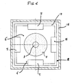
- the composite assembly of the blocks and spacers is housed in a housing and the latter is shaped such that at least one of the intermediate plates slides on the side wall of the housing. housing.
- This embodiment of the invention has the advantage of reinforcing the resistance of the spring to buckling.
- the housing and the spacer trays are preferably shaped and dimensioned such that a majority (preferably all) of the trays of the composite assembly slide on the side wall of the housing.
- the spring according to the invention has the advantage of a simpler design.
- the geometry of the spacers is simpler, the assembly of the spring is simplified and the margin of tolerance in the sizing of the prominences (especially their thickness) is doubled compared to what it was in the previous spring of the document WO-2010/012049-A1 .
- the spring according to the invention can be used in all applications requiring compression springs.
- the spring according to the invention finds an interesting application in buffers or bumpers intended for railway vehicles, such as locomotives and railcars, passenger railway cars and railway wagons for the transport of goods or livestock.
- the spring according to the invention finds an additional application in suspension systems of wheeled or chain road vehicles, such as motor cars, trucks, motorcycles, trolleys or trailers, civil engineering or military engines and railway cars. It is also found applications in stationary industrial machines, for example machine tools, as well as for the suspension of moving mechanical parts in household appliances (washing machine, dishwasher, etc.).
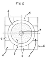
- the spring represented figures 1 and 2 comprises a composite assembly of tubular blocks 1 of thermoplastic elastomer, alternating with metal spacers 2.
- the blocks 1 have the appearance of flanges, whose peripheral side face has a convex curved profile.
- Each of the tubular blocks 1 was obtained by subjecting a straight cylindrical tube to a mechanical compression / expansion treatment comprising compression of the cylindrical tube beyond the elastic deformation limit of the elastomer and expansion. At the end of the mechanical compression / expansion treatment, the cylindrical tube retains a remanent deformation giving it the appearance of the blocks 1.
- the blocks 1 and the spacers 2 are pierced at their center to form an axial duct 3 through the composite assembly.
- the inserts 2 comprise a flat square plate 4 which overflows the blocks 1.
- each plate 4 carries four prominences 5.
- These prominences 5 are situated on one side of the plate, the other face of which is completely flat.
- the face bearing the prominences 5 is referred to as the "prominent face” in this specification.
- the other side (which does not have prominences) is called “flat face”.
- the prominences 5 form corbels at the periphery of the blocks 1.
- a substantial gap 6 is maintained between the prominences 5 and the peripheral surface of the blocks 1. The function of this gap 6 will be explained later.
- the inserts 2 are divided into three sets of inserts.
- a first series designated as a whole by the reference notation 7
- the plates 3 are positioned so that their prominent face is directed in the direction of the arrow Y.
- a second series of dividers designated 8
- the 3 trays are positioned so that their prominent face is directed in the opposite direction to that of the arrow Y.
- These two sets of spacers are separated by a medial spacer 9 formed of a pair of trays 4 contiguous on their flat face .
- the set of tabs 2, the intermediate spacer 9 and blocks 1 is sandwiched between two end supports 10, a face 11 is contiguous to a block 1.
- the face 11 of the supports 10 is substantially flat.
- a metal bar 12 passes through the aforementioned axial duct and enters an opening 16 of the end supports 10. The bar 12 serves to ensure the cohesion of the composite assembly of the blocks 1 and the trays 4. It has the additional function of avoid buckling of the composite assembly when the spring is compressed between the supports 10.
- the bar 12 passes freely through all the plates 4.
- the bar is welded to the plates 4 of the intermediate spacer 3.
- the openings 16 of the supports 10 may advantageously contain bearings (not shown) made of anti-friction material to facilitate the sliding of the bar 12 during normal use of the spring.
- the blocks 1 undergo compression / expansion cycles.
- the prominences 5 limit the axial compression of blocks 1.
- the thickness of the prominences 5 is calculated so that the compression tension in the blocks 1 is less than the elastic limit of the elastomer when the composite assembly is completely compressed, fully 5.
- the blocks 1 When the blocks 1 are in a compression phase, they swell transversely.
- the gap 6 between the blocks and the prominences 5 serves to allow the blocks to swell and deform freely.
- the square plates 2 may, alternatively, be replaced by circular or elliptical disks or by polygonal plates, for example hexagonal or octagonal.
- the four protuberances 5 of the trays 4 can be replaced by a single annular prominence at the periphery of the tray.
- the tray 4 is octagonal and its prominent face has two thick prominences along two opposite ridges. Along the other six edges, the plate bears on its prominent face, a rib 17 whose height is less than that of the prominences 5. The rib 17 serves to stiffen the plate. It does not participate in limiting the axial compression of the blocks 1.
- the composite assembly of the blocks 1 and the trays 4 of the figure 1 is enclosed in a box 15 of square or rectangular section.
Landscapes
- Engineering & Computer Science (AREA)
- General Engineering & Computer Science (AREA)
- Mechanical Engineering (AREA)
- Springs (AREA)
Claims (15)
- Druckfeder bestehend aus einer Zusammensetzung von zylindrischen Blöcken (1) aus elastisch druckbaren Elastomerwerkstoff und unverformbaren Zwischenscheiben (2), die zwischen den Blöcken als Sandwich gehalten sind, und diese überschreiten, die oberganannte Zwischenscheiben darstellend, in ihrem Teil, der die Blöcke überschreitet, Vorsprungen (5), die bei vollem Hub der Feder, den Druck der Blöcken begrenzt, dadurch gekennzeichnet, dass die Zwischenscheiben (2) aus grundsätzlich flache Platten (4) bestehen, dessen eine einzige Seite die obengenannten Vorsprungen darstellen.
- Feder gemäss Anspruch 1, dadurch gekennzeichnet, dass für jede Zusammensetzung eines Blöckes aus Elastomerwerkstoff (1) zwischen zwei Platten (4), die Vorsprungen (5) von einer der Platten in Richtung der Seite der anderen Platte, die keine Vorsprungen darstellt, gerichtet sind.
- Feder gemäss Anspruch 1 oder 2, dadurch gekennzeichnet, dass die Zusammensetzung zwischen zwei Endstützen (10) als Sandwich gehalten ist.
- Feder gemäss Anspruch 3, dadurch gekennzeichnet, dass mindestens einer der beiden Endstützen (10), eine gegenüber den Vorsprungen (5) einer Platte (4), mit Zwischenschaltung eines Elastomer Blöckes, eine grundsätzlich flache Seite darstellt.
- Feder nach irgendeinem der Ansprüchen 1 bis 4, dadurch gekennzeichnet, dass ein zylindricher Stab (12) durch einer Reihe von Öffnungen (3), die durch den Blöcken und Platten (4) verfertigt sind, gleitet.
- Feder nach irgendeinem der Ansprüchen 1 bis 5, dadurch gekennzeichnet, dass mindestens eine der Zwischenscheiben (2) aus ein Paar flache Platten (4), die sich bei einer Seite unterstützen und die vorgenannten Vorsprungen (5) auf der anderen Seite enthalten, besteht.
- Feder gemäss Anspruch 6, dadurch gekennzeichnet, dass falls die Zusammensetzung zwischen zwei Endstütze (10) als Sandwich gehalten ist, jeder Endstutz (10) besitzt eine grundsätzlich flache Seite in Berührung mit einem Block (1).
- Feder gemäss Anspruch 6 oder 7, dadurch gekennzeichnet, dass falls ein zylindrischer Stab (12) durch die Platten (4) gleitet, dieser Stab ist an dem Paar von Platten, die sich gegen einander unterstützen, befestigt.
- Feder nach irgendeinem der Ansprüchen 6 bis 8, dadurch gekennzeichnet, dass das Paar von Platten (4), die sich gegen einander unterstützen, eine grundsätzlich mittlere Lage in der Zusammensetzung besetzt.
- Feder nach irgendeinem der Ansprüchen 1 bis 9, dadurch gekennzeichnet, dass die Vorsprungen so dimensioniert sind, dass die Druckspannung in dem Elastomerwerkstoff der Blöcken (1) sei niedriger als seine elastische Grenze wenn die Zusammensetzung so zusammengepresst ist, dass die Vorsprungen (5) gegen die Platten (4) gedrückt sind.
- Feder nach irgendeinem der Ansprüchen 1 bis 10, dadurch gekennzeichnet, dass die Blöcke (1) rund und die Platten (4) polygonal sind.
- Feder gemäss Anspruch 11, dadurch gekennzeichnet, dass die Vorsprungen einförmisch am Rand der Platten verteilt sind.
- Ferder gemäss Anspruch 12, dadurch gekennzeichnet, dass die Platten augerichtet sind, dass ihren jeweiligen Vorsprungen ausgerichtet sind.
- Feder gemäss Anspruch 12 oder 13, dadurch gekennzeichnet, dass die Platten eine Umfangsrippe zwischen den Vorsprungen enthalten.
- Feder nach irgendeinem der Ansprüchen 1 bis 14, dadurch gekennzeichent, dass das Elastomerwerkstoff der Blöcken (1) ein thermoplastisches Elastomer ist, dass einanderfolgend eine Druckverformung über die elastische Grenze des Elastomerwerkstoffes und eine Entspannung ertragen hat.
Priority Applications (1)
| Application Number | Priority Date | Filing Date | Title |
|---|---|---|---|
| PL13447008T PL2657562T3 (pl) | 2012-04-24 | 2013-04-22 | Sprężyna ściskana |
Applications Claiming Priority (1)
| Application Number | Priority Date | Filing Date | Title |
|---|---|---|---|
| BE201200272A BE1020628A3 (fr) | 2012-04-24 | 2012-04-24 | Ressort de compression. |
Publications (2)
| Publication Number | Publication Date |
|---|---|
| EP2657562A1 EP2657562A1 (de) | 2013-10-30 |
| EP2657562B1 true EP2657562B1 (de) | 2015-03-04 |
Family
ID=48227123
Family Applications (1)
| Application Number | Title | Priority Date | Filing Date |
|---|---|---|---|
| EP13447008.7A Active EP2657562B1 (de) | 2012-04-24 | 2013-04-22 | Druckfeder |
Country Status (3)
| Country | Link |
|---|---|
| EP (1) | EP2657562B1 (de) |
| BE (1) | BE1020628A3 (de) |
| PL (1) | PL2657562T3 (de) |
Families Citing this family (2)
| Publication number | Priority date | Publication date | Assignee | Title |
|---|---|---|---|---|
| DE102016003607B4 (de) * | 2016-03-29 | 2022-08-18 | Günther Zimmer | Feder-Dämpfersystem aus mehreren hintereinander angeordneten Feder-Dämpferelementen |
| CN116274769B (zh) * | 2023-03-09 | 2026-01-20 | 常州格林电力机械制造有限公司 | 一种用于环形弹簧组的导向装置 |
Family Cites Families (9)
| Publication number | Priority date | Publication date | Assignee | Title |
|---|---|---|---|---|
| DE587498C (de) * | 1933-11-03 | Continental Gummi Werke Akt Ge | Abfederung des Untergestells durch zwischen Metallplatten gelagerte Gummipuffer | |
| DE6604167U (de) * | 1965-04-03 | 1969-12-18 | Continental Gummi Werke Ag | Mehrteilige, geschichtete feder aus gummi oder gummiartigen kunststoffen. |
| US4198037A (en) | 1976-12-28 | 1980-04-15 | Miner Enterprises, Inc. | Method of making polyester elastomer compression spring and resulting product |
| US4211429A (en) * | 1978-04-19 | 1980-07-08 | Howard D U | Adjustable suspension assembly |
| GB2180618B (en) | 1982-08-27 | 1989-05-10 | Miner Enterprises | Polymeric apparatus and method of making same |
| US5529327A (en) * | 1995-02-08 | 1996-06-25 | Aprebic Industry Co., Ltd. | Shock absorbing device for a bicycle |
| US5868384A (en) | 1997-04-11 | 1999-02-09 | Miner Enterprises, Inc. | Composite elastomeric spring |
| EP1630446A1 (de) | 2004-08-23 | 2006-03-01 | Bureau Mertens | Druckfeder und dazugehöriges Herstellungsverfahren |
| BE1018231A5 (fr) * | 2008-07-29 | 2010-07-06 | Mertens Rudi | Ressort de compression, amortisseur de chocs pour dispositif d'attelage automatique de vehicules et vehicule equipe d'un tel amortisseur de chocs. |
-
2012
- 2012-04-24 BE BE201200272A patent/BE1020628A3/fr active
-
2013
- 2013-04-22 EP EP13447008.7A patent/EP2657562B1/de active Active
- 2013-04-22 PL PL13447008T patent/PL2657562T3/pl unknown
Also Published As
| Publication number | Publication date |
|---|---|
| BE1020628A3 (fr) | 2014-02-04 |
| EP2657562A1 (de) | 2013-10-30 |
| PL2657562T3 (pl) | 2015-07-31 |
Similar Documents
| Publication | Publication Date | Title |
|---|---|---|
| EP2657562B1 (de) | Druckfeder | |
| FR2815593A1 (fr) | Rotule de liaison, par exemple pour barre anti-roulis de vehicule roulant | |
| EP2876326A1 (de) | Verfahren zur Erneuerung und Verwendung von Bremsscheiben vom Typ rückwärtiger Stator mit Bremsklötzen, montierte Scheibe und entsprechender Scheibenstapel. | |
| EP2904290B1 (de) | Torsionsdämpfende vorrichtung mit federn und kippbaren sitzen | |
| FR2734763A1 (fr) | Roue de chemin de fer polyblocs | |
| EP2390166A1 (de) | Ökologisches modulares Fahrzeugkonzept | |
| FR2932859A1 (fr) | Dispositif de transmission de couple notamment pour compresseur de climatisation | |
| EP1817506B1 (de) | Druckfeder und verfahren zu ihrer herstellung | |
| EP1756441B1 (de) | Reibungsvorrichtung für eine kupplung, im besonderen eines kraftfahrzeuges | |
| BE1018231A5 (fr) | Ressort de compression, amortisseur de chocs pour dispositif d'attelage automatique de vehicules et vehicule equipe d'un tel amortisseur de chocs. | |
| FR2960506A1 (fr) | Vehicule modulaire ecologique | |
| WO2019185835A1 (fr) | Dispositif d'amortissement de torsion avec siege de ressorts a guidage axial | |
| EP2153084B1 (de) | Reibungskupplung mit verbessertem reibring und verbessertem führungsring | |
| EP4158217B1 (de) | Bremssystem eines fahrzeuges | |
| FR3028223A1 (fr) | Glissiere comportant un dispositif de positionnement et siege de vehicule automobile comportant une telle glissiere | |
| FR2874860A1 (fr) | Barre anti-devers de vehicule automobile | |
| FR2986292A1 (fr) | Dispositif de securite pour un ressort helicoidal de suspension, comportant une gaine | |
| FR2726870A1 (fr) | Plateau durci pour un ensemble formant disque amortisseur, et son procede de fabrication | |
| FR2865511A1 (fr) | Procede de fabrication d'un dispositif d'articulation a masse elastique constituee de blocs de nature differente. | |
| EP3591251B1 (de) | Schwingungsdämpfender zentrierring für fuss des torsionsrohrs einer luftfahrzeugbremse, und mit einem solchen ring augestattete bremse | |
| FR3058771A1 (fr) | Dispositif de transmission mecanique | |
| FR2989137A1 (fr) | Procede d'utilisation et de renovation d'un disque d'une pile de disques d'un frein d'un vehicule. | |
| WO2020127639A1 (fr) | Dispositif de transmission de couple avec des ressorts en serie et systeme de transmission de couple comprenant un tel dispositif | |
| FR3036817A1 (fr) | Assemblage de deux pieces ayant une incompatibilite de soudure | |
| FR3055935A1 (fr) | Couronne de differentiel de transmission pour vehicule et differentiel de transmission |
Legal Events
| Date | Code | Title | Description |
|---|---|---|---|
| PUAI | Public reference made under article 153(3) epc to a published international application that has entered the european phase |
Free format text: ORIGINAL CODE: 0009012 |
|
| AK | Designated contracting states |
Kind code of ref document: A1 Designated state(s): AL AT BE BG CH CY CZ DE DK EE ES FI FR GB GR HR HU IE IS IT LI LT LU LV MC MK MT NL NO PL PT RO RS SE SI SK SM TR |
|
| AX | Request for extension of the european patent |
Extension state: BA ME |
|
| 17P | Request for examination filed |
Effective date: 20140311 |
|
| RBV | Designated contracting states (corrected) |
Designated state(s): AL AT BE BG CH CY CZ DE DK EE ES FI FR GB GR HR HU IE IS IT LI LT LU LV MC MK MT NL NO PL PT RO RS SE SI SK SM TR |
|
| RIC1 | Information provided on ipc code assigned before grant |
Ipc: F16F 3/087 20060101AFI20140904BHEP |
|
| GRAP | Despatch of communication of intention to grant a patent |
Free format text: ORIGINAL CODE: EPIDOSNIGR1 |
|
| INTG | Intention to grant announced |
Effective date: 20141022 |
|
| GRAS | Grant fee paid |
Free format text: ORIGINAL CODE: EPIDOSNIGR3 |
|
| GRAA | (expected) grant |
Free format text: ORIGINAL CODE: 0009210 |
|
| AK | Designated contracting states |
Kind code of ref document: B1 Designated state(s): AL AT BE BG CH CY CZ DE DK EE ES FI FR GB GR HR HU IE IS IT LI LT LU LV MC MK MT NL NO PL PT RO RS SE SI SK SM TR |
|
| REG | Reference to a national code |
Ref country code: GB Ref legal event code: FG4D Free format text: NOT ENGLISH |
|
| REG | Reference to a national code |
Ref country code: CH Ref legal event code: EP |
|
| REG | Reference to a national code |
Ref country code: IE Ref legal event code: FG4D Free format text: LANGUAGE OF EP DOCUMENT: FRENCH |
|
| REG | Reference to a national code |
Ref country code: AT Ref legal event code: REF Ref document number: 714177 Country of ref document: AT Kind code of ref document: T Effective date: 20150415 |
|
| REG | Reference to a national code |
Ref country code: DE Ref legal event code: R096 Ref document number: 602013001124 Country of ref document: DE Effective date: 20150416 |
|
| REG | Reference to a national code |
Ref country code: SE Ref legal event code: TRGR |
|
| REG | Reference to a national code |
Ref country code: AT Ref legal event code: MK05 Ref document number: 714177 Country of ref document: AT Kind code of ref document: T Effective date: 20150304 Ref country code: NL Ref legal event code: VDEP Effective date: 20150304 |
|
| PG25 | Lapsed in a contracting state [announced via postgrant information from national office to epo] |
Ref country code: HR Free format text: LAPSE BECAUSE OF FAILURE TO SUBMIT A TRANSLATION OF THE DESCRIPTION OR TO PAY THE FEE WITHIN THE PRESCRIBED TIME-LIMIT Effective date: 20150304 Ref country code: LT Free format text: LAPSE BECAUSE OF FAILURE TO SUBMIT A TRANSLATION OF THE DESCRIPTION OR TO PAY THE FEE WITHIN THE PRESCRIBED TIME-LIMIT Effective date: 20150304 Ref country code: FI Free format text: LAPSE BECAUSE OF FAILURE TO SUBMIT A TRANSLATION OF THE DESCRIPTION OR TO PAY THE FEE WITHIN THE PRESCRIBED TIME-LIMIT Effective date: 20150304 Ref country code: NO Free format text: LAPSE BECAUSE OF FAILURE TO SUBMIT A TRANSLATION OF THE DESCRIPTION OR TO PAY THE FEE WITHIN THE PRESCRIBED TIME-LIMIT Effective date: 20150604 Ref country code: ES Free format text: LAPSE BECAUSE OF FAILURE TO SUBMIT A TRANSLATION OF THE DESCRIPTION OR TO PAY THE FEE WITHIN THE PRESCRIBED TIME-LIMIT Effective date: 20150304 |
|
| REG | Reference to a national code |
Ref country code: PL Ref legal event code: T3 |
|
| REG | Reference to a national code |
Ref country code: LT Ref legal event code: MG4D |
|
| PG25 | Lapsed in a contracting state [announced via postgrant information from national office to epo] |
Ref country code: GR Free format text: LAPSE BECAUSE OF FAILURE TO SUBMIT A TRANSLATION OF THE DESCRIPTION OR TO PAY THE FEE WITHIN THE PRESCRIBED TIME-LIMIT Effective date: 20150605 Ref country code: AT Free format text: LAPSE BECAUSE OF FAILURE TO SUBMIT A TRANSLATION OF THE DESCRIPTION OR TO PAY THE FEE WITHIN THE PRESCRIBED TIME-LIMIT Effective date: 20150304 Ref country code: RS Free format text: LAPSE BECAUSE OF FAILURE TO SUBMIT A TRANSLATION OF THE DESCRIPTION OR TO PAY THE FEE WITHIN THE PRESCRIBED TIME-LIMIT Effective date: 20150304 Ref country code: LV Free format text: LAPSE BECAUSE OF FAILURE TO SUBMIT A TRANSLATION OF THE DESCRIPTION OR TO PAY THE FEE WITHIN THE PRESCRIBED TIME-LIMIT Effective date: 20150304 |
|
| PG25 | Lapsed in a contracting state [announced via postgrant information from national office to epo] |
Ref country code: NL Free format text: LAPSE BECAUSE OF FAILURE TO SUBMIT A TRANSLATION OF THE DESCRIPTION OR TO PAY THE FEE WITHIN THE PRESCRIBED TIME-LIMIT Effective date: 20150304 |
|
| PG25 | Lapsed in a contracting state [announced via postgrant information from national office to epo] |
Ref country code: EE Free format text: LAPSE BECAUSE OF FAILURE TO SUBMIT A TRANSLATION OF THE DESCRIPTION OR TO PAY THE FEE WITHIN THE PRESCRIBED TIME-LIMIT Effective date: 20150304 Ref country code: SK Free format text: LAPSE BECAUSE OF FAILURE TO SUBMIT A TRANSLATION OF THE DESCRIPTION OR TO PAY THE FEE WITHIN THE PRESCRIBED TIME-LIMIT Effective date: 20150304 Ref country code: PT Free format text: LAPSE BECAUSE OF FAILURE TO SUBMIT A TRANSLATION OF THE DESCRIPTION OR TO PAY THE FEE WITHIN THE PRESCRIBED TIME-LIMIT Effective date: 20150706 Ref country code: CZ Free format text: LAPSE BECAUSE OF FAILURE TO SUBMIT A TRANSLATION OF THE DESCRIPTION OR TO PAY THE FEE WITHIN THE PRESCRIBED TIME-LIMIT Effective date: 20150304 Ref country code: RO Free format text: LAPSE BECAUSE OF FAILURE TO SUBMIT A TRANSLATION OF THE DESCRIPTION OR TO PAY THE FEE WITHIN THE PRESCRIBED TIME-LIMIT Effective date: 20150304 |
|
| PG25 | Lapsed in a contracting state [announced via postgrant information from national office to epo] |
Ref country code: MC Free format text: LAPSE BECAUSE OF FAILURE TO SUBMIT A TRANSLATION OF THE DESCRIPTION OR TO PAY THE FEE WITHIN THE PRESCRIBED TIME-LIMIT Effective date: 20150304 Ref country code: IS Free format text: LAPSE BECAUSE OF FAILURE TO SUBMIT A TRANSLATION OF THE DESCRIPTION OR TO PAY THE FEE WITHIN THE PRESCRIBED TIME-LIMIT Effective date: 20150704 |
|
| REG | Reference to a national code |
Ref country code: DE Ref legal event code: R097 Ref document number: 602013001124 Country of ref document: DE |
|
| PG25 | Lapsed in a contracting state [announced via postgrant information from national office to epo] |
Ref country code: IT Free format text: LAPSE BECAUSE OF FAILURE TO SUBMIT A TRANSLATION OF THE DESCRIPTION OR TO PAY THE FEE WITHIN THE PRESCRIBED TIME-LIMIT Effective date: 20150304 |
|
| PLBE | No opposition filed within time limit |
Free format text: ORIGINAL CODE: 0009261 |
|
| STAA | Information on the status of an ep patent application or granted ep patent |
Free format text: STATUS: NO OPPOSITION FILED WITHIN TIME LIMIT |
|
| REG | Reference to a national code |
Ref country code: IE Ref legal event code: MM4A |
|
| PG25 | Lapsed in a contracting state [announced via postgrant information from national office to epo] |
Ref country code: DK Free format text: LAPSE BECAUSE OF FAILURE TO SUBMIT A TRANSLATION OF THE DESCRIPTION OR TO PAY THE FEE WITHIN THE PRESCRIBED TIME-LIMIT Effective date: 20150304 |
|
| 26N | No opposition filed |
Effective date: 20151207 |
|
| PG25 | Lapsed in a contracting state [announced via postgrant information from national office to epo] |
Ref country code: SI Free format text: LAPSE BECAUSE OF FAILURE TO SUBMIT A TRANSLATION OF THE DESCRIPTION OR TO PAY THE FEE WITHIN THE PRESCRIBED TIME-LIMIT Effective date: 20150304 |
|
| REG | Reference to a national code |
Ref country code: FR Ref legal event code: PLFP Year of fee payment: 4 |
|
| PG25 | Lapsed in a contracting state [announced via postgrant information from national office to epo] |
Ref country code: IE Free format text: LAPSE BECAUSE OF NON-PAYMENT OF DUE FEES Effective date: 20150422 |
|
| REG | Reference to a national code |
Ref country code: CH Ref legal event code: PL |
|
| PG25 | Lapsed in a contracting state [announced via postgrant information from national office to epo] |
Ref country code: MT Free format text: LAPSE BECAUSE OF FAILURE TO SUBMIT A TRANSLATION OF THE DESCRIPTION OR TO PAY THE FEE WITHIN THE PRESCRIBED TIME-LIMIT Effective date: 20150304 |
|
| PG25 | Lapsed in a contracting state [announced via postgrant information from national office to epo] |
Ref country code: CH Free format text: LAPSE BECAUSE OF NON-PAYMENT OF DUE FEES Effective date: 20160430 Ref country code: LI Free format text: LAPSE BECAUSE OF NON-PAYMENT OF DUE FEES Effective date: 20160430 |
|
| REG | Reference to a national code |
Ref country code: FR Ref legal event code: PLFP Year of fee payment: 5 |
|
| PG25 | Lapsed in a contracting state [announced via postgrant information from national office to epo] |
Ref country code: HU Free format text: LAPSE BECAUSE OF FAILURE TO SUBMIT A TRANSLATION OF THE DESCRIPTION OR TO PAY THE FEE WITHIN THE PRESCRIBED TIME-LIMIT; INVALID AB INITIO Effective date: 20130422 Ref country code: BG Free format text: LAPSE BECAUSE OF FAILURE TO SUBMIT A TRANSLATION OF THE DESCRIPTION OR TO PAY THE FEE WITHIN THE PRESCRIBED TIME-LIMIT Effective date: 20150304 |
|
| PG25 | Lapsed in a contracting state [announced via postgrant information from national office to epo] |
Ref country code: CY Free format text: LAPSE BECAUSE OF FAILURE TO SUBMIT A TRANSLATION OF THE DESCRIPTION OR TO PAY THE FEE WITHIN THE PRESCRIBED TIME-LIMIT Effective date: 20150304 |
|
| PG25 | Lapsed in a contracting state [announced via postgrant information from national office to epo] |
Ref country code: TR Free format text: LAPSE BECAUSE OF FAILURE TO SUBMIT A TRANSLATION OF THE DESCRIPTION OR TO PAY THE FEE WITHIN THE PRESCRIBED TIME-LIMIT Effective date: 20150304 |
|
| PG25 | Lapsed in a contracting state [announced via postgrant information from national office to epo] |
Ref country code: LU Free format text: LAPSE BECAUSE OF NON-PAYMENT OF DUE FEES Effective date: 20150422 |
|
| GBPC | Gb: european patent ceased through non-payment of renewal fee |
Effective date: 20170422 |
|
| PG25 | Lapsed in a contracting state [announced via postgrant information from national office to epo] |
Ref country code: GB Free format text: LAPSE BECAUSE OF NON-PAYMENT OF DUE FEES Effective date: 20170422 |
|
| REG | Reference to a national code |
Ref country code: FR Ref legal event code: PLFP Year of fee payment: 6 |
|
| PG25 | Lapsed in a contracting state [announced via postgrant information from national office to epo] |
Ref country code: SM Free format text: LAPSE BECAUSE OF FAILURE TO SUBMIT A TRANSLATION OF THE DESCRIPTION OR TO PAY THE FEE WITHIN THE PRESCRIBED TIME-LIMIT Effective date: 20150304 |
|
| PG25 | Lapsed in a contracting state [announced via postgrant information from national office to epo] |
Ref country code: MK Free format text: LAPSE BECAUSE OF FAILURE TO SUBMIT A TRANSLATION OF THE DESCRIPTION OR TO PAY THE FEE WITHIN THE PRESCRIBED TIME-LIMIT Effective date: 20150304 |
|
| PG25 | Lapsed in a contracting state [announced via postgrant information from national office to epo] |
Ref country code: AL Free format text: LAPSE BECAUSE OF FAILURE TO SUBMIT A TRANSLATION OF THE DESCRIPTION OR TO PAY THE FEE WITHIN THE PRESCRIBED TIME-LIMIT Effective date: 20150304 |
|
| REG | Reference to a national code |
Ref country code: BE Ref legal event code: MM Effective date: 20200430 |
|
| PG25 | Lapsed in a contracting state [announced via postgrant information from national office to epo] |
Ref country code: BE Free format text: LAPSE BECAUSE OF NON-PAYMENT OF DUE FEES Effective date: 20200430 |
|
| REG | Reference to a national code |
Ref country code: BE Ref legal event code: NE Effective date: 20210421 Ref country code: BE Ref legal event code: NF Effective date: 20210506 |
|
| PG25 | Lapsed in a contracting state [announced via postgrant information from national office to epo] |
Ref country code: BE Free format text: LAPSE BECAUSE OF NON-PAYMENT OF DUE FEES Effective date: 20200430 |
|
| PGRI | Patent reinstated in contracting state [announced from national office to epo] |
Ref country code: BE Effective date: 20210506 |
|
| PGFP | Annual fee paid to national office [announced via postgrant information from national office to epo] |
Ref country code: DE Payment date: 20250127 Year of fee payment: 13 |
|
| PGFP | Annual fee paid to national office [announced via postgrant information from national office to epo] |
Ref country code: SE Payment date: 20250417 Year of fee payment: 13 |
|
| PGFP | Annual fee paid to national office [announced via postgrant information from national office to epo] |
Ref country code: PL Payment date: 20251211 Year of fee payment: 14 |
|
| PGFP | Annual fee paid to national office [announced via postgrant information from national office to epo] |
Ref country code: BE Payment date: 20260206 Year of fee payment: 14 |
|
| PGFP | Annual fee paid to national office [announced via postgrant information from national office to epo] |
Ref country code: FR Payment date: 20260206 Year of fee payment: 14 |