EP2657382A2 - Yarn monitoring device and yarn winding machine including the same - Google Patents
Yarn monitoring device and yarn winding machine including the same Download PDFInfo
- Publication number
- EP2657382A2 EP2657382A2 EP13158743.8A EP13158743A EP2657382A2 EP 2657382 A2 EP2657382 A2 EP 2657382A2 EP 13158743 A EP13158743 A EP 13158743A EP 2657382 A2 EP2657382 A2 EP 2657382A2
- Authority
- EP
- European Patent Office
- Prior art keywords
- yarn
- section
- monitoring device
- blowing
- wall surface
- Prior art date
- Legal status (The legal status is an assumption and is not a legal conclusion. Google has not performed a legal analysis and makes no representation as to the accuracy of the status listed.)
- Granted
Links
- 238000012806 monitoring device Methods 0.000 title claims abstract description 78
- 238000004804 winding Methods 0.000 title claims description 33
- 238000007664 blowing Methods 0.000 claims abstract description 106
- 239000012530 fluid Substances 0.000 claims description 31
- 238000011144 upstream manufacturing Methods 0.000 claims description 16
- 238000009987 spinning Methods 0.000 description 34
- 230000007547 defect Effects 0.000 description 12
- 239000000835 fiber Substances 0.000 description 9
- 238000004140 cleaning Methods 0.000 description 7
- 239000012634 fragment Substances 0.000 description 6
- 230000002159 abnormal effect Effects 0.000 description 4
- 238000012544 monitoring process Methods 0.000 description 4
- 230000003287 optical effect Effects 0.000 description 3
- 230000002093 peripheral effect Effects 0.000 description 3
- 238000001514 detection method Methods 0.000 description 2
- 239000000463 material Substances 0.000 description 2
- 239000000758 substrate Substances 0.000 description 2
- 238000005299 abrasion Methods 0.000 description 1
- 239000000919 ceramic Substances 0.000 description 1
- 230000007423 decrease Effects 0.000 description 1
- 230000003247 decreasing effect Effects 0.000 description 1
- 230000000694 effects Effects 0.000 description 1
- 230000001678 irradiating effect Effects 0.000 description 1
- 238000000034 method Methods 0.000 description 1
- 230000001105 regulatory effect Effects 0.000 description 1
- 239000011347 resin Substances 0.000 description 1
- 229920005989 resin Polymers 0.000 description 1
- 239000000126 substance Substances 0.000 description 1
Images


Classifications
-
- D—TEXTILES; PAPER
- D01—NATURAL OR MAN-MADE THREADS OR FIBRES; SPINNING
- D01H—SPINNING OR TWISTING
- D01H13/00—Other common constructional features, details or accessories
- D01H13/14—Warning or safety devices, e.g. automatic fault detectors, stop motions ; Monitoring the entanglement of slivers in drafting arrangements
-
- B—PERFORMING OPERATIONS; TRANSPORTING
- B65—CONVEYING; PACKING; STORING; HANDLING THIN OR FILAMENTARY MATERIAL
- B65H—HANDLING THIN OR FILAMENTARY MATERIAL, e.g. SHEETS, WEBS, CABLES
- B65H54/00—Winding, coiling, or depositing filamentary material
- B65H54/70—Other constructional features of yarn-winding machines
- B65H54/702—Arrangements for confining or removing dust
-
- B—PERFORMING OPERATIONS; TRANSPORTING
- B65—CONVEYING; PACKING; STORING; HANDLING THIN OR FILAMENTARY MATERIAL
- B65H—HANDLING THIN OR FILAMENTARY MATERIAL, e.g. SHEETS, WEBS, CABLES
- B65H63/00—Warning or safety devices, e.g. automatic fault detectors, stop-motions ; Quality control of the package
- B65H63/06—Warning or safety devices, e.g. automatic fault detectors, stop-motions ; Quality control of the package responsive to presence of irregularities in running material, e.g. for severing the material at irregularities ; Control of the correct working of the yarn cleaner
- B65H63/062—Electronic slub detector
- B65H63/065—Electronic slub detector using photo-electric sensing means, i.e. the defect signal is a variation of light energy
-
- B—PERFORMING OPERATIONS; TRANSPORTING
- B65—CONVEYING; PACKING; STORING; HANDLING THIN OR FILAMENTARY MATERIAL
- B65H—HANDLING THIN OR FILAMENTARY MATERIAL, e.g. SHEETS, WEBS, CABLES
- B65H2701/00—Handled material; Storage means
- B65H2701/30—Handled filamentary material
- B65H2701/31—Textiles threads or artificial strands of filaments
Definitions
- the present invention relates to a configuration in which fluid is blown to remove yarn wastes attached to a travelling passage of a yarn in a yarn monitoring device adapted to monitor a traveling yarn.
- the yarn winding machine such as a spinning machine or an automatic winder, adapted to wind a yarn around a bobbin.
- the yarn winding machine of such kind includes a yarn monitoring device (a yarn clearer) adapted to monitor status of a travelling yarn in real time, and a yarn defect(a yarn portion having abnormal quality) is detected by the yarn monitoring device.
- yarn wastes small fiber wastes, yarn fragments and/or other wastes, and the like (hereinafter collectively referred to as "yarn wastes") may fly and attach to each portion.
- yarn wastes small fiber wastes, yarn fragments and/or other wastes, and the like
- the status of the yarn may not be accurately monitored by the yarn monitoring device.
- Japanese Unexamined Patent Publication No. 2005-232650 discloses a spinning machine including a cleaning nozzle adapted to blow and remove the yarn wastes and the like accumulated in a detecting head of the yarn clearer. The cleaning nozzle of which one end is arranged facing an upper side of the yarn clearer, blows compressed air around the detecting head.
- the cleaning nozzle is desired to be capable of removing the yarn wastes more reliably with less amount of flow. Thus, consideration may be made to enhance efficiency and reliability of the removal of the yarn wastes by devising an arrangement or a shape of the cleaning nozzle.
- Japanese Unexamined Patent Publication No. 2005-232650 merely discloses "a cleaning nozzle is arranged facing an upper side of the yarn clearer", and does not disclose a detailed description regarding an arrangement or a shape of such cleaning nozzle.
- An object of the present invention is to provide a configuration capable of efficiently and reliably removing attached yarn wastes in a yarn monitoring device.
- a yarn monitoring device includes a yarn passage defining member, a detecting section, and a blowing section.
- the yarn passage defining member includes a wall surface defining a yarn passage for enabling passage of a yarn travelling along a yarn path.
- the detecting section is adapted to detect at least at a portion of the wall surface of the yarn passage, status of the yarn.
- the blowing section is adapted to blow fluid in a blowing direction towards at least a portion of the wall surface. When viewed in a direction orthogonal to the yarn path and parallel to the wall surface, the blowing direction is set diagonal with respect to the wall surface. The fluid flows along the wall surface.
- the blowing direction is preferably set diagonal with respect to the wall surface.
- the yarn passage is formed as a groove along the yarn path, and the blowing section preferably blows the fluid towards an interior of the yarn passage.
- the blowing section preferably blows the fluid from a slit-like blowing mouth.
- the yarn wastes can be removed in a wide area since the belt-like fluid can be applied to the wall surface.
- the blowing section preferably blows the fluid from upstream toward downstream in a travelling direction of the yarn.
- the travelling yarn could bring back the yarn wastes that should have been blown away towards upstream by the fluid. Since the fluid is blown from upstream to the wall surface, the yarn wastes are blown away to downstream, and the yarn wastes are not brought back by the yarn. The yarn wastes thus can be efficiently removed.
- the yarn monitoring device includes a first block having the yarn passage defining member, and a second block having the blowing section.
- the first block and the second block are arranged next to each other in a direction parallel to the yarn path.
- a supply path of the fluid blown from the blowing section is provided in the second block.
- the first block and the yarn passage defining member can be formed into a simple shape.
- the yarn monitoring device preferably includes a cutter adapted to cut the yarn, and a cutter blowing section adapted to blow the fluid to the cutter in the second block.
- the fluid can be blown to the cutter with pinpoint accuracy. Yarn fragments and the like caught in the cutter thus can be reliably removed. Since the cutter or the like is arranged in the second block, the shape of the first block can be simplified.
- the detecting section includes a light emitting section adapted to emit light to the yarn, and a light receiving section arranged facing the light emitting section with the yarn path therebetween and adapted to receive the light emitted by the light emitting section.
- the blowing direction of the blowing section is set diagonal with respect to the wall surface where the light receiving section is arranged.
- a yarn winding machine includes a winding section adapted to wind a yarn, and the yarn monitoring device adapted to monitor the yarn to be wound by the yarn winding section.
- the yarn winding machine reliably enables the removal of the yarn wastes attached to the yarn passage of the yarn monitoring device with a small amount of the fluid flow. Therefore, the accuracy of the yarn monitoring by the yarn monitoring device can be maintained at low cost, and the quality of the wound yarn can be enhanced.
- a spinning machine 1 as a yarn winding machine illustrated in FIG. 1 includes a plurality of spinning units 2 arranged next to each other, and a yarn joining cart 3.
- each spinning unit 2 includes a draft device 4, a spinning device 5, a yarn monitoring device 6, a yarn accumulating device 7, and a winding section 8 in this order from upstream towards downstream.
- "Upstream” and “downstream” in the present specification respectively indicate upstream and downstream in a travelling direction of a fiber bundle and a spun yarn at the time of spinning.
- the draft device 4 stretches a sliver (material of a fiber bundle) 9 into a fiber bundle 10.
- the draft device 4 includes a plurality of draft rollers 11, 12, 13, and 14, and opposing rollers arranged facing each draft roller.
- the plurality of draft rollers 11, 12, 13, and 14 are respectively rotated at a predetermined rotation speed.
- the draft device 4 stretches (drafts) the sliver 9 into the fiber bundle 10.
- the fiber bundle 10 drafted in the draft device 4 is supplied to the spinning device 5.
- the spinning device 5 generates the spun yarn 15 by adding twists to the fiber bundle 10.
- the configuration of the spinning device 5 is not limited in particular, the spinning device 5 according to the present embodiment is configured as a pneumatic spinning device.
- the pneumatic spinning device 5 adds the twists to the fiber bundle 10 by generating a whirling airflow in its interior and applying the whirling airflow to the fiber bundle 10.
- the spun yarn 15 generated in the spinning device 5 passes through the yarn monitoring device 6.
- the yarn monitoring device 6 monitors status of the travelling spun yarn 15 and detects a yarn portion with abnormal quality in the spun yarn 15 (a yarn defect).
- the yarn monitoring device 6 includes a cutter 16 adapted to cut the spun yarn 15. The configuration of the yarn monitoring device 6 will be described in detail later.
- the spun yarn that has passed through the yarn monitoring device 6 is wound around a bobbin 17 by the winding section 8.
- the winding section 8 includes a cradle arm 19, a winding drum 20, and a traverse device 21.
- the cradle arm 19 rotatably supports the bobbin 17 around which the spun yarn 15 is wound.
- the winding drum 20 rotates the bobbin 17 by being rotated in contact with an outer peripheral surface of the bobbin 17.
- the traverse device 21 includes a traverse guide 22 adapted to be driven from side to side (in a direction of a winding width of the bobbin 17) while being engaged with the spun yarn 15. The spun yarn 15 to be wound around the bobbin 17 is traversed by the traverse device 21.
- the spun yarn 15 can be generated from the sliver 9 and wound around the bobbin 17.
- the bobbin 17 around which the spun yarn 15 is wound is referred as to a "package".
- the yarn accumulating device 7 is arranged between the yarn monitoring device 6 and the winding section 8.
- the yarn accumulating device 7, as illustrated in FIG. 2 includes a yarn accumulating roller 23, and an electric motor 25 adapted to rotate the yarn accumulating roller 23.
- the yarn accumulating roller 23 can temporarily accumulate a predetermined amount of the spun yarn 15 by winding the spun yarn 15 around an outer peripheral surface thereof. Since the yarn accumulating device 7 temporarily accumulates the spun yarn 15 in such a manner, the yarn accumulating device 7 functions as a kind of a buffer. Thus, a fault (a slackening of the spun yarn 15, for example) where a spinning speed in the spinning device 5 and a winding speed in the winding section 8 do not correspond to each other for some reason can be resolved.
- Each spinning unit 2 includes a unit control section 26.
- the unit control section 26 is adapted to appropriately control each configuration provided in the spinning unit 2.
- the yarn joining cart 3 as illustrated in FIG.1 and FIG.2 , includes a yarn joining device 27 and suction devices (a suction pipe 28 and a suction mouth 29).
- the yarn joining device 27 is a device adapted to join yarn ends (yarn joining). Although the configuration of the yarn joining device 27 is not limited in particular, an air splicer, for example, that twists the yarn ends together by a whirling airflow may be employed.
- the suction pipe 28 sucks and catches a yarn end fed from the spinning device 5, and guides the yarn end to the yarn joining device 27.
- the suction mouth 29 sucks and catches a yarn end from a package 18 supported by the winding section 8, and guides the yarn end to the yarn joining device 27.
- the yarn monitoring device 6 sends a yarn defect detection signal to the unit control section 26 when detecting the yarn defect (an abnormal portion in the spun yarn 15).
- the unit control section 26 immediately activates the cutter 16 to cut the spun yarn 15 when receiving the yarn defect detection signal.
- the spun yarn 15 that is downstream of the cut portion is once wound into the package 18.
- the spun yarn 15 wound into the package 18 includes a portion of the yarn defect detected by the yarn monitoring device 6.
- the unit control section 26 stops the winding in the winding section 8.
- the unit control section 26 then sends a control signal to the yarn joining cart 3, and controls the yarn joining cart 3 to travel to a front of the spinning unit 2 where the yarn defect has been detected.
- the yarn joining cart 3 After stopping at the front of the spinning unit 2, the yarn joining cart 3 sucks and catches a yarn end fed from the spinning device 5, and guides the yarn end to the yarn joining device 27 by the suction pipe 28.
- the spun yarn 15 is then guided to the outer peripheral surface of the yarn accumulating roller 23 by a hooking mechanism that is not illustrated, and accumulated again.
- a slackening of the spun yarn 15 that occurs during a yarn joining operation is thus resolved by the yarn accumulating device 7.
- the yarn joining cart 3 sucks and catches the yarn end wound into the package 18, and guides the yarn end to the yarn joining device 27 by the suction mouth 29. In this case, the portion of the yarn defect wound into the package 18 is sucked and pulled out by the suction mouth 29. The portion of the yarn defect detected by the yarn monitoring device 6 is thus removed from the package 18.
- the yarn joining device 27 joins the yarn ends together (yarn joining) that has been guided by the suction pipe 28 and the suction mouth 29.
- the spun yarn 15 that has been cut by the cutter 16 thus becomes connected again between the spinning device 5 and the winding section 8.
- the unit control section 26 resumes winding of the spun yarn 15 by the winding section 8.
- the yarn defect detected by the yarn monitoring device 6 can be removed, and the winding of the spun yarn 15 into the package 18 can be resumed.
- the yarn monitoring device 6 includes a holder (sensor holding member) 30, a housing 31, and yarn path guides 32 and 33.
- the holder 30 is a member made of plastic, where a detecting section (such as sensor) for detecting the status of the spun yarn 15 is embedded in the interior thereof.
- the holder 30 is provided with a first yarn path 34 where the spun yarn 15 passes through. Therefore, the holder 30 may be referred to as a yarn passage defining member.
- the first yarn passage 34 provided in the holder 30 is formed as a groove along a travelling path (hereinafter referred as to a "yarn path") of the spun yarn 15.
- An outline shape of an inner wall surface of the first yarn passage 34 is formed as a substantially U-shape when cut in a plane orthogonal to the yarn path. That is, when the first yarn passage 34 is viewed in a direction parallel to the yarn path, one end portion of the first yarn passage 34 is formed to be opened, and the other end portion is formed to be closed (see FIG. 4B ).
- a front-back direction of the yarn monitoring device 6 is defined by a direction in which the opened side of the first yarn passage 34 faces (an upper side of FIG.4B ) as a "front", and by an opposite direction thereto as a "back". That is, the opened side of the first yarn passage 34 is a front side of the yarn monitoring device 6.
- the first yarn passage 34 includes a pair of side wall surfaces 35 and 35 arranged in parallel to each other with the yarn path therebetween.
- the side wall surfaces 35 and 35 are arranged parallel to the front-back direction of the yarn monitoring device 6 (a vertical direction of FIG. 4B ) and the yarn path.
- the spun yarn 15 passing through the first yarn passage 34 travels between the side wall surfaces 35 and 35.
- the yarn monitoring device 6 is configured as an optical yarn monitoring device adapted to detect the status of the spun yarn 15 by irradiating light to the spun yarn 15.
- the detecting section includes a light emitting element (a light emitting section) 37 and a light receiving element (a light receiving section) 38.
- An appropriate light emitting element such as Light Emitting Diode (LED), for example, may be adopted as the light emitting element 37.
- the light receiving element 38 configured as a photodiode converts an intensity of received light into an electric signal and outputs the electric signal.
- the light receiving element 38 is arranged such that a light receiving surface thereof constitutes a part of the side wall surface 35 of the first yarn passage 34.
- a transparent plate 39 made of resin is provided as a part of the side wall surface 35 opposite to the light receiving element 38.
- the light emitting element 37 is arranged opposite to the first yarn passage 34 with the transparent plate 39 therebetween (inside the holder 30).
- the light emitting element 37 irradiates light to the first yarn passage 34 via the transparent plate 39.
- the light emitting element 37 and the light receiving element 38 are arranged facing each other with the yarn path therebetween.
- the intensity of the light received by the light receiving element 38 changes according to a thickness of the spun yarn 15.
- the thickness of the spun yarn 15 thus can be detected based on the intensity of the light received by the light receiving element 38.
- the detecting section of the yarn monitoring device 6 monitors the status of the spun yarn 15 (specifically, the thickness of the spun yarn 15) passing between the side wall surfaces 35.
- the housing 31 includes a first block 41 and a second block 42 arranged next to each other in a direction parallel to the yarn path.
- the first block 41 and the second block 42 are made of plastic, respectively.
- the first block 41 and the second block 42 are formed as a different body and separable.
- the holder 30 is mounted to the first block 41.
- the first block 41 accommodates a circuit substrate 44 adapted to control the light emitting element 37 and the light receiving element 38 of the detecting section.
- the second block 42 is arranged upstream of the first block 41. As illustrated in FIG. 3 and FIG. 7 , the second block 42 is provided with a second yarn passage 43 where the spun yarn 15 passes through.
- the second yarn passage 43 is formed as a groove along the yarn path, and its cross-sectional shape is substantially U-shaped.
- the second yarn passage 43 is formed so as to communicate with the first yarn passage 34.
- the cutter 16 is arranged in the second block 42.
- the cutter 16 can cut the spun yarn 15 travelling in the second yarn passage 43.
- a cutter drive mechanism (not illustrated) adapted to drive the cutter 16 to cut the spun yarn 15 is arranged in the second block 42.
- the yarn path guides 32 and 33 are members for regulating the yarn path of the spun yarn 15 and configured by material having abrasion resistance (ceramic in the present embodiment). Each of the yarn path guides 32 and 33 are separately arranged upstream and downstream of the holder 30. The spun yarn 15 travels while making contact with the yarn path guides 32 and 33. Since a travelling position of the spun yarn 15 with respect to the holder 30 is stabilized, a status of the spun yarn 15 can be stably monitored in the detecting section.
- the yarn monitoring device 6 includes a blowing section 45 adapted to blow a fluid (specifically, compressed air) to the side wall surface 35 of the first yarn passage 34.
- a fluid specifically, compressed air
- the yarn wastes and the like attached to the side wall surface 35 thus can be blown away.
- the compressed air may be blown periodically, or non-periodically under appropriate timing. Since the side wall surface 35 (especially the transparent plate 39 and the light receiving surface of the light receiving element 38) can be kept clean in such a manner, the yarn monitoring device 6 can accurately monitor the status of the spun yarn 15.
- the object of the blowing section 45 is to blow away the yarn wastes attached to the light receiving surface of the light receiving element 38 and/or the transparent plate 39 by blowing the compressed air.
- a configuration may be considered in which the blowing section 45 is provided in proximity to the transparent plate 39 and the light receiving element 38 to blow the air with pinpoint accuracy to the transparent plate 39 and the light receiving element 38.
- the blowing section 45 is required to be provided in the holder 30, for example.
- an air supply path to the blowing section 45 is required to be provided in the holder 30, which makes the shape of the holder 30 complicated.
- the blowing section 45 may be considered to be provided in the first block 41 of the housing 31, in this case, the air supply path is required to be provided in the first block 41.
- the circuit substrate 44 and the like are arranged in the first block 41, there is no extra space and the air path is difficult to be formed. Furthermore, if the air path is provided in the first block 41, a shape of the first block 41 becomes complicated.
- the flow of the air can merely be applied to a narrow area of the transparent plate 39 and the light receiving element 38. Therefore, to entirely clean the transparent plate 39 and the light receiving surface of the light receiving element 38, a plurality of blowing sections is required to be provided. When the number of the blowing sections increases, a consumption of the compressed air increases and efficiency decreases.
- the blowing section 45 is adapted to diagonally blow the compressed air to the side wall surface 35 of the first yarn passage 34.
- the compressed air can flow along the side wall surface 35.
- the flow of the air can be applied to a wide area of the side wall surface 35.
- a blowing direction of the air from the blowing section 45 is illustrated by thin line arrows in FIG. 3 and FIG. 5 to FIG. 7 .
- the blowing direction of the compressed air from the blowing section 45 is set diagonal with respect to the side wall surface 35. Therefore, the blowing direction of the air from the blowing section 45 has a vector component in a direction parallel to the yarn path (a longitudinal direction of the first yarn passage 34, a vertical direction in FIG. 5 ).
- the air blown in this direction to the side wall surface 35 swiftly flows towards the longitudinal direction of the first yarn passage 34 along the side wall surface 35.
- the side wall surface 35 of the first yarn passage 34 can be entirely cleaned.
- the blowing section 45 is adapted to blow the air from upstream towards downstream in the travelling direction to the side wall surface 35 of the first yarn passage 34.
- the yarn wastes attached to the side wall surface 35 can be blown away towards downstream. Accordingly, the blown yarn wastes do not return to the yarn monitoring device 6 by being accompanied by the travelling spun yarn 15.
- the blowing direction of the compressed air from the blowing section 45 is set diagonal with respect to the side wall surface 35 even when viewed in a direction parallel to the yarn path (see FIG. 6 ). That is, the blowing direction of the air from the blowing section 45 has a vector component in the front-back direction of the yarn monitoring device 6 (a depth direction of the first yarn passage 34, a vertical direction in FIG. 6 ). The air blown in this direction to the side wall surface 35 also flows in the depth direction of the first yarn passage 34 along the side wall surface 35. Thus, the blown air from the blowing section 45 can be applied to a wider area of the side wall surface 35.
- the blowing section 45 is arranged outside of the first yarn passage 34. More specifically, when viewed in a direction parallel to the yarn path, the blowing section 45 is arranged to the front of an opened end of the substantially U-shaped first yarn passage 34. Thus, the blowing section 45 blows the air towards an interior of the first yarn passage 34. By diagonally blowing the air towards the interior of the groove-like first yarn passage 34, the spiral flow of the air can be generated in the first yarn passage 34 (see FIG. 6 ).
- the blowing section 45 is adapted to blow the compressed air to either of the pair of the side wall surfaces 35 and 35 facing to each other in the first yarn passage 34. Therefore, the compressed air from the blowing section 45 is not directly applied to the other side wall surface 35. However, as described above, by producing the spiral airflow in the first yarn passage 34, the airflow can also be applied to the side wall surface 35 where the compressed air is not directly blown from the blowing section 45. The airflow thus can be applied to the pair of both the side wall surfaces 35 and 35. Therefore, the blown air from one blowing section 45 can clean both the transparent plate 39 and the light receiving surface of the light receiving element 38.
- the blowing section 45 is adapted to blow the compressed air from a slit-like blowing mouth. Since belt-like compressed air having a width thus can be blown to the side wall surface 35, the air can be applied to the side wall surface 35 in a wider area.
- the yarn monitoring device 6 includes a cutter blowing section 46 separately from the blowing section 45.
- the cutter blowing section 46 is provided inside the second yarn passage 43 and adapted to blow the compressed air to the cutter 16.
- the cutter blowing section 46 is configured as a round-hole-like nozzle. The air thus can be blown to the cutter 16 with pinpoint accuracy.
- the cutter blowing section 46 when viewed in a direction parallel to the yarn path, the cutter blowing section 46 is provided in a closed-end portion of the U-shaped second yarn passage 43 (a back of the second yarn passage 43).
- the cutter blowing section 46 is adapted to blow the compressed air towards an opened side (towards a front) of the second yarn passage 43.
- the yarn fragments and the like of the spun yarn 15 caught in the cutter 16 thus can be blown away towards an outside of the second yarn passage 43.
- the belt-like air is blown from the slit-like mouth to the side wall surface 35 for applying the air to a wide area, while the air is blown with pinpoint accuracy from the round-hole-like nozzle to the cutter 16. Since methods to blow the compressed air vary according to an object, the yarn wastes and the like can be removed more efficiently. As a result, since an effect of a cleaning is efficiently achieved with a small amount of flow, the consumption of the compressed air can be decreased.
- the blowing section 45 is adapted to blow the air from upstream in the travelling direction of the spun yarn 15 in a direction diagonal to the side wall surface 35 of the first yarn passage 34 provided in the holder 30. Therefore, the blowing section 45 is sufficient to be arranged upstream of the holder 30 in the travelling direction, and the holder 30 and the blowing section 45 are not necessarily arranged at the same position in the travelling direction.
- the blowing section 45 is provided not in the first block 41 having the holder 30, but in the second block 42 arranged upstream of the first block 41.
- the blowing section 45 is not provided in the holder 30 and the first block 41, the holder 30 and the first block 41 can be simply configured.
- the second block 42 is connected to a compressed air supply hose 48 adapted to supply the compressed air to the yarn monitoring device 6.
- a supply path 49 adapted to supply the compressed air from the compressed air supply hose 48 to the blowing section 45 is provided in the second block 42.
- an air supply path 50 for the cutter blowing section 46 is also provided in the second block 42. Since the compressed air supply paths 49 and 50 are provided in the second block 42, an air supply path is not required to be provided in the holder 30 and the first block 41. Therefore, the shapes of the holder 30 and the first block 41 can be simply configured.
- the yarn monitoring device 6 includes the holder 30, the detecting section, and the blowing section 45.
- the first yarn passage 34 for enabling passage of the spun yarn 15 travelling along the predetermined yarn path is provided in the holder 30.
- the detecting section is adapted to detect at least at a portion of the side wall surface 35 of the first yarn passage 34, the status of the spun yarn 15.
- the blowing section 45 is adapted to blow the compressed air in the predetermined blowing direction to the side wall surface 35 of the first yarn passage 34. When viewed in a direction orthogonal to the yarn path and parallel to the side wall surface 35, the blowing direction is set diagonal with respect to the side wall surface 35.
- the compressed air applied to the side wall surface 35 flows along the side wall surface 35.
- the airflow can be applied to a wide area of the side wall surface 35, the yarn wastes attached to the side wall surface 35 can be removed efficiently with a small amount of flow.
- the blowing direction when viewed in a direction parallel to the yarn path, is set diagonal with respect to the side wall surface 35.
- the yarn wastes on the side wall surface 35 can be removed in a wider area.
- the first yarn passage 34 is formed as a groove along the yarn path, and the blowing section 45 blows the compressed air towards the interior of the first yarn passage 34.
- the blowing section 45 blows the compressed air from the slit-like blowing mouth.
- the yarn wastes can be removed in a wide area.
- the blowing section 45 blows the compressed air from upstream towards downstream in the travelling direction of the spun yarn 15.
- the travelling spun yarn 15 could bring back the yarn wastes that should have been blown away towards upstream by the compressed air. Therefore, as described above, by blowing the compressed air from upstream to the side wall surface 35, the yarn wastes are blown away to downstream and not brought back by the spun yarn 15. The yarn wastes thus can be removed efficiently.
- the yarn monitoring device 6 includes the first block 41 having the holder 30 and the second block 42 having the blowing section 45.
- the first block 41 and the second block 42 are arranged next to each other in the direction parallel to the yarn path.
- the compressed air supply path 49 for the blowing section 45 is provided in the second block 42.
- the compressed air supply path 49 is not required to be provided in the first block 41 and the holder 30, the first block 41 and the holder 30 can be formed into a simple shape.
- the yarn monitoring device 6 includes the cutter 16 adapted to cut the spun yarn 15, and the cutter blowing section 46 adapted to blow the compressed air to the cutter 16 in the second block 42.
- the cutter blowing section 46 By arranging the cutter blowing section 46 separately from the blowing section 45 in such a manner, the fluid can be blown to the cutter 16 with pinpoint accuracy. The yarn fragments and the like of the spun yarn 15 caught in the cutter 16 thus can be reliably removed. Since the cutter 16 or the like is arranged in the second block 42, the shape of the first block 41 can be simplified.
- the spinning machine 1 includes the winding section 8 adapted to wind the spun yarn 15 and the yarn monitoring device 6 adapted to monitor the spun yarn 15 to be wound by the winding section 8.
- the spinning machine 1 reliably enables the removal of the yarn wastes attached to the first yarn passage 34 of the yarn monitoring device 6 with a small amount of the fluid flow. Therefore, the accuracy of the yarn monitoring by the yarn monitoring device 6 can be maintained at low cost, and the quality of the wound spun yarn 15 can be enhanced.
- the configuration of the present application may be applied not only to a spinning machine but to another kind of a yarn winding machine such as an automatic winder.
- An automatic winder is a device adapted to unwind a yarn of a yarn supplying bobbin and rewind the yarn around a winding bobbin while applying a predetermined tension to the yarn.
- the status of the yarn to be rewound can be accurately monitored by employing the yarn monitoring device according to the invention of the present application in the automatic winder.
- the yarn monitoring device is described as an optical yarn monitoring device having one light emitting element and one light receiving element, but, without limiting thereto, the yarn monitoring device may include a plurality of light emitting elements and/or a plurality of light receiving elements.
- the thickness of the yarn is detected by monitoring the intensity of the light blocked by the yarn, but, without limiting thereto, whether or not a foreign substance is included in the yarn may be detected by monitoring, for example, intensity of reflected light from the yarn.
- the detecting section may be adapted to detect the status of the yarn not only by an optical sensor but, for example, by a capacitance sensor. Even in this case, since the detecting accuracy is lowered when the yarn wastes are accumulated in the first yarn passage 34, there is an advantage to remove the yarn wastes by the above-described configuration.
- the abnormal portion of the yarn (the yarn defect) is detected by the yarn monitoring device 6, but the embodiment is not limited thereto.
- the yarn monitoring device may be configured to detect and monitor at least one kind of status of the travelling yarn such as a travelling speed of the yarn or a travelled length of the yarn.
Landscapes
- Engineering & Computer Science (AREA)
- Textile Engineering (AREA)
- Mechanical Engineering (AREA)
- Quality & Reliability (AREA)
- Spinning Or Twisting Of Yarns (AREA)
- Filamentary Materials, Packages, And Safety Devices Therefor (AREA)
Abstract
Description
- The present invention relates to a configuration in which fluid is blown to remove yarn wastes attached to a travelling passage of a yarn in a yarn monitoring device adapted to monitor a traveling yarn.
- There is known a yarn winding machine, such as a spinning machine or an automatic winder, adapted to wind a yarn around a bobbin. The yarn winding machine of such kind includes a yarn monitoring device (a yarn clearer) adapted to monitor status of a travelling yarn in real time, and a yarn defect(a yarn portion having abnormal quality) is detected by the yarn monitoring device.
- In the yarn winding machine, when the yarn is wound, small fiber wastes, yarn fragments and/or other wastes, and the like (hereinafter collectively referred to as "yarn wastes") may fly and attach to each portion. For example, when a large volume of yarn wastes attaches to the yarn monitoring device, the status of the yarn may not be accurately monitored by the yarn monitoring device. Japanese Unexamined Patent Publication No.
2005-232650 - Since the compressed air needs to be generated by a compressor, consuming a large amount of the compressed air becomes a cause of cost increase. Therefore, the cleaning nozzle is desired to be capable of removing the yarn wastes more reliably with less amount of flow. Thus, consideration may be made to enhance efficiency and reliability of the removal of the yarn wastes by devising an arrangement or a shape of the cleaning nozzle.
- However, Japanese Unexamined Patent Publication No.
2005-232650 - An object of the present invention is to provide a configuration capable of efficiently and reliably removing attached yarn wastes in a yarn monitoring device.
- According to an aspect of the present invention, a yarn monitoring device includes a yarn passage defining member, a detecting section, and a blowing section. The yarn passage defining member includes a wall surface defining a yarn passage for enabling passage of a yarn travelling along a yarn path. The detecting section is adapted to detect at least at a portion of the wall surface of the yarn passage, status of the yarn. The blowing section is adapted to blow fluid in a blowing direction towards at least a portion of the wall surface. When viewed in a direction orthogonal to the yarn path and parallel to the wall surface, the blowing direction is set diagonal with respect to the wall surface. The fluid flows along the wall surface.
- By diagonally blowing the fluid to the wall surface, the fluid that hits the wall surface flows along the wall surface. Thus, since the fluid can be applied to a wide area on the wall surface, yarn wastes attached to the wall surface can be efficiently removed with a small amount of flow.
- In the yarn monitoring device, when viewed in a direction parallel to the yarn path, the blowing direction is preferably set diagonal with respect to the wall surface.
- By blowing the fluid diagonally in such a manner even when viewed from another direction, the yarn wastes attached to the wall can be removed in wider area.
- In the yarn monitoring device, the yarn passage is formed as a groove along the yarn path, and the blowing section preferably blows the fluid towards an interior of the yarn passage.
- By blowing the fluid diagonally towards the interior of the groove-like yarn passage, a spiral flow is generated in the yarn passage. The yarn wastes attached to the wall surface thus can be more reliably removed with less amount of flow.
- In the yarn monitoring device, the blowing section preferably blows the fluid from a slit-like blowing mouth.
- By blowing the fluid from the slit, the yarn wastes can be removed in a wide area since the belt-like fluid can be applied to the wall surface.
- In the yarn monitoring device, the blowing section preferably blows the fluid from upstream toward downstream in a travelling direction of the yarn.
- If the fluid is blown from downstream to the wall surface, the travelling yarn could bring back the yarn wastes that should have been blown away towards upstream by the fluid. Since the fluid is blown from upstream to the wall surface, the yarn wastes are blown away to downstream, and the yarn wastes are not brought back by the yarn. The yarn wastes thus can be efficiently removed.
- The yarn monitoring device includes a first block having the yarn passage defining member, and a second block having the blowing section. The first block and the second block are arranged next to each other in a direction parallel to the yarn path. A supply path of the fluid blown from the blowing section is provided in the second block.
- Since the fluid supply path is not required to be provided in the first block and the yarn passage defining member, the first block and the yarn passage defining member can be formed into a simple shape.
- The yarn monitoring device preferably includes a cutter adapted to cut the yarn, and a cutter blowing section adapted to blow the fluid to the cutter in the second block.
- By arranging a dedicated blowing section for the cutter, the fluid can be blown to the cutter with pinpoint accuracy. Yarn fragments and the like caught in the cutter thus can be reliably removed. Since the cutter or the like is arranged in the second block, the shape of the first block can be simplified.
- In the yarn monitoring device, the detecting section includes a light emitting section adapted to emit light to the yarn, and a light receiving section arranged facing the light emitting section with the yarn path therebetween and adapted to receive the light emitted by the light emitting section. The blowing direction of the blowing section is set diagonal with respect to the wall surface where the light receiving section is arranged.
- According to another aspect of the present invention, a yarn winding machine includes a winding section adapted to wind a yarn, and the yarn monitoring device adapted to monitor the yarn to be wound by the yarn winding section.
- The yarn winding machine reliably enables the removal of the yarn wastes attached to the yarn passage of the yarn monitoring device with a small amount of the fluid flow. Therefore, the accuracy of the yarn monitoring by the yarn monitoring device can be maintained at low cost, and the quality of the wound yarn can be enhanced.
-
-
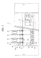
FIG. 1 is a front view illustrating an overall structure of a spinning machine according to an embodiment of the present invention. -
FIG. 2 is a side view of a spinning unit. -
FIG. 3 is an exterior perspective view of a yarn monitoring device. -
FIG. 4A and FIG. 4B are schematic cross sectional views of a holder. -
FIG. 5 is a front view of the yarn monitoring device. -
FIG. 6 is a planar cross sectional view of a first block. -
FIG. 7 is a planar cross sectional view of a second block. - Next, a spinning machine according to an embodiment of the present invention will be described with reference to the drawings. A
spinning machine 1 as a yarn winding machine illustrated inFIG. 1 includes a plurality ofspinning units 2 arranged next to each other, and ayarn joining cart 3. - As illustrated in
FIG. 2 , eachspinning unit 2 includes adraft device 4, aspinning device 5, ayarn monitoring device 6, ayarn accumulating device 7, and awinding section 8 in this order from upstream towards downstream. "Upstream" and "downstream" in the present specification respectively indicate upstream and downstream in a travelling direction of a fiber bundle and a spun yarn at the time of spinning. - The
draft device 4 stretches a sliver (material of a fiber bundle) 9 into afiber bundle 10. Thedraft device 4 includes a plurality ofdraft rollers draft rollers sliver 9 supplied from a sliver case that is not illustrated by holding between therotating draft rollers draft device 4 stretches (drafts) thesliver 9 into thefiber bundle 10. Thefiber bundle 10 drafted in thedraft device 4 is supplied to thespinning device 5. - The
spinning device 5 generates the spunyarn 15 by adding twists to thefiber bundle 10. Although the configuration of thespinning device 5 is not limited in particular, thespinning device 5 according to the present embodiment is configured as a pneumatic spinning device. Thepneumatic spinning device 5 adds the twists to thefiber bundle 10 by generating a whirling airflow in its interior and applying the whirling airflow to thefiber bundle 10. - The spun
yarn 15 generated in thespinning device 5 passes through theyarn monitoring device 6. Theyarn monitoring device 6 monitors status of the travelling spunyarn 15 and detects a yarn portion with abnormal quality in the spun yarn 15 (a yarn defect). Theyarn monitoring device 6 includes acutter 16 adapted to cut the spunyarn 15. The configuration of theyarn monitoring device 6 will be described in detail later. - The spun yarn that has passed through the
yarn monitoring device 6 is wound around abobbin 17 by the windingsection 8. The windingsection 8 includes acradle arm 19, a windingdrum 20, and atraverse device 21. - The
cradle arm 19 rotatably supports thebobbin 17 around which the spunyarn 15 is wound. The windingdrum 20 rotates thebobbin 17 by being rotated in contact with an outer peripheral surface of thebobbin 17. Thetraverse device 21 includes atraverse guide 22 adapted to be driven from side to side (in a direction of a winding width of the bobbin 17) while being engaged with the spunyarn 15. The spunyarn 15 to be wound around thebobbin 17 is traversed by thetraverse device 21. - By the
spinning unit 2 configured as described above, the spunyarn 15 can be generated from thesliver 9 and wound around thebobbin 17. Thebobbin 17 around which the spunyarn 15 is wound is referred as to a "package". - In the spinning
machine 1 according to the present embodiment, theyarn accumulating device 7 is arranged between theyarn monitoring device 6 and the windingsection 8. Theyarn accumulating device 7, as illustrated inFIG. 2 , includes ayarn accumulating roller 23, and anelectric motor 25 adapted to rotate theyarn accumulating roller 23. - The
yarn accumulating roller 23 can temporarily accumulate a predetermined amount of the spunyarn 15 by winding the spunyarn 15 around an outer peripheral surface thereof. Since theyarn accumulating device 7 temporarily accumulates the spunyarn 15 in such a manner, theyarn accumulating device 7 functions as a kind of a buffer. Thus, a fault (a slackening of the spunyarn 15, for example) where a spinning speed in thespinning device 5 and a winding speed in the windingsection 8 do not correspond to each other for some reason can be resolved. - Each
spinning unit 2 includes aunit control section 26. Theunit control section 26 is adapted to appropriately control each configuration provided in thespinning unit 2. - The
yarn joining cart 3, as illustrated inFIG.1 andFIG.2 , includes ayarn joining device 27 and suction devices (asuction pipe 28 and a suction mouth 29). - The
yarn joining device 27 is a device adapted to join yarn ends (yarn joining). Although the configuration of theyarn joining device 27 is not limited in particular, an air splicer, for example, that twists the yarn ends together by a whirling airflow may be employed. Thesuction pipe 28 sucks and catches a yarn end fed from thespinning device 5, and guides the yarn end to theyarn joining device 27. Thesuction mouth 29 sucks and catches a yarn end from apackage 18 supported by the windingsection 8, and guides the yarn end to theyarn joining device 27. - Next, an operation of when the yarn defect is detected by the
yarn monitoring device 6 will be described briefly. - The
yarn monitoring device 6 sends a yarn defect detection signal to theunit control section 26 when detecting the yarn defect (an abnormal portion in the spun yarn 15). Theunit control section 26 immediately activates thecutter 16 to cut the spunyarn 15 when receiving the yarn defect detection signal. The spunyarn 15 that is downstream of the cut portion is once wound into thepackage 18. In this case, the spunyarn 15 wound into thepackage 18 includes a portion of the yarn defect detected by theyarn monitoring device 6. Furthermore, theunit control section 26 stops the winding in the windingsection 8. Theunit control section 26 then sends a control signal to theyarn joining cart 3, and controls theyarn joining cart 3 to travel to a front of thespinning unit 2 where the yarn defect has been detected. - After stopping at the front of the
spinning unit 2, theyarn joining cart 3 sucks and catches a yarn end fed from thespinning device 5, and guides the yarn end to theyarn joining device 27 by thesuction pipe 28. The spunyarn 15 is then guided to the outer peripheral surface of theyarn accumulating roller 23 by a hooking mechanism that is not illustrated, and accumulated again. A slackening of the spunyarn 15 that occurs during a yarn joining operation is thus resolved by theyarn accumulating device 7. Almost simultaneously, theyarn joining cart 3 sucks and catches the yarn end wound into thepackage 18, and guides the yarn end to theyarn joining device 27 by thesuction mouth 29. In this case, the portion of the yarn defect wound into thepackage 18 is sucked and pulled out by thesuction mouth 29. The portion of the yarn defect detected by theyarn monitoring device 6 is thus removed from thepackage 18. - The
yarn joining device 27 joins the yarn ends together (yarn joining) that has been guided by thesuction pipe 28 and thesuction mouth 29. The spunyarn 15 that has been cut by thecutter 16 thus becomes connected again between the spinningdevice 5 and the windingsection 8. - After a yarn joining operation in the
yarn joining device 27 is completed, theunit control section 26 resumes winding of the spunyarn 15 by the windingsection 8. By the operations described above, the yarn defect detected by theyarn monitoring device 6 can be removed, and the winding of the spunyarn 15 into thepackage 18 can be resumed. - Next, the configuration of the
yarn monitoring device 6 will be described in detail. - As illustrated in
FIG. 3 , theyarn monitoring device 6 according to the present embodiment includes a holder (sensor holding member) 30, ahousing 31, and yarn path guides 32 and 33. - The
holder 30 is a member made of plastic, where a detecting section (such as sensor) for detecting the status of the spunyarn 15 is embedded in the interior thereof. Theholder 30 is provided with afirst yarn path 34 where the spunyarn 15 passes through. Therefore, theholder 30 may be referred to as a yarn passage defining member. Thefirst yarn passage 34 provided in theholder 30 is formed as a groove along a travelling path (hereinafter referred as to a "yarn path") of the spunyarn 15. - An outline shape of an inner wall surface of the
first yarn passage 34 is formed as a substantially U-shape when cut in a plane orthogonal to the yarn path. That is, when thefirst yarn passage 34 is viewed in a direction parallel to the yarn path, one end portion of thefirst yarn passage 34 is formed to be opened, and the other end portion is formed to be closed (seeFIG. 4B ). In a following description regarding theyarn monitoring device 6, when viewed in a direction parallel to the yarn path, a front-back direction of theyarn monitoring device 6 is defined by a direction in which the opened side of thefirst yarn passage 34 faces (an upper side ofFIG.4B ) as a "front", and by an opposite direction thereto as a "back". That is, the opened side of thefirst yarn passage 34 is a front side of theyarn monitoring device 6. - The
first yarn passage 34 includes a pair of side wall surfaces 35 and 35 arranged in parallel to each other with the yarn path therebetween. The side wall surfaces 35 and 35 are arranged parallel to the front-back direction of the yarn monitoring device 6 (a vertical direction ofFIG. 4B ) and the yarn path. The spunyarn 15 passing through thefirst yarn passage 34 travels between the side wall surfaces 35 and 35. - Next, a configuration of the detecting section will be described with reference to
FIG. 4A and FIG. 4B . Theyarn monitoring device 6 according to the present embodiment is configured as an optical yarn monitoring device adapted to detect the status of the spunyarn 15 by irradiating light to the spunyarn 15. Specifically, the detecting section includes a light emitting element (a light emitting section) 37 and a light receiving element (a light receiving section) 38. An appropriate light emitting element such as Light Emitting Diode (LED), for example, may be adopted as thelight emitting element 37. Thelight receiving element 38 configured as a photodiode converts an intensity of received light into an electric signal and outputs the electric signal. - The
light receiving element 38 is arranged such that a light receiving surface thereof constitutes a part of theside wall surface 35 of thefirst yarn passage 34. Atransparent plate 39 made of resin is provided as a part of theside wall surface 35 opposite to thelight receiving element 38. Thelight emitting element 37 is arranged opposite to thefirst yarn passage 34 with thetransparent plate 39 therebetween (inside the holder 30). Thelight emitting element 37 irradiates light to thefirst yarn passage 34 via thetransparent plate 39. Thelight emitting element 37 and thelight receiving element 38 are arranged facing each other with the yarn path therebetween. - In the configuration described above, light from the
light emitting element 37 is received by thelight receiving element 38 with a portion of the light being blocked by the spunyarn 15. Therefore, the intensity of the light received by thelight receiving element 38 changes according to a thickness of the spunyarn 15. The thickness of the spunyarn 15 thus can be detected based on the intensity of the light received by thelight receiving element 38. - As described above, from a portion of the
side wall surface 35 of thefirst yarn passage 34, the detecting section of theyarn monitoring device 6 monitors the status of the spun yarn 15 (specifically, the thickness of the spun yarn 15) passing between the side wall surfaces 35. - Next, the
housing 31 of theyarn monitoring device 6 will be described. Thehousing 31 includes afirst block 41 and asecond block 42 arranged next to each other in a direction parallel to the yarn path. Thefirst block 41 and thesecond block 42 are made of plastic, respectively. Thefirst block 41 and thesecond block 42 are formed as a different body and separable. - As illustrated in
FIG. 6 , theholder 30 is mounted to thefirst block 41. Thefirst block 41 accommodates acircuit substrate 44 adapted to control thelight emitting element 37 and thelight receiving element 38 of the detecting section. - The
second block 42 is arranged upstream of thefirst block 41. As illustrated inFIG. 3 andFIG. 7 , thesecond block 42 is provided with asecond yarn passage 43 where the spunyarn 15 passes through. Thesecond yarn passage 43 is formed as a groove along the yarn path, and its cross-sectional shape is substantially U-shaped. Thesecond yarn passage 43 is formed so as to communicate with thefirst yarn passage 34. - The
cutter 16 is arranged in thesecond block 42. Thecutter 16 can cut the spunyarn 15 travelling in thesecond yarn passage 43. A cutter drive mechanism (not illustrated) adapted to drive thecutter 16 to cut the spunyarn 15 is arranged in thesecond block 42. - The yarn path guides 32 and 33 are members for regulating the yarn path of the spun
yarn 15 and configured by material having abrasion resistance (ceramic in the present embodiment). Each of the yarn path guides 32 and 33 are separately arranged upstream and downstream of theholder 30. The spunyarn 15 travels while making contact with the yarn path guides 32 and 33. Since a travelling position of the spunyarn 15 with respect to theholder 30 is stabilized, a status of the spunyarn 15 can be stably monitored in the detecting section. - The
yarn monitoring device 6 according to the present embodiment includes ablowing section 45 adapted to blow a fluid (specifically, compressed air) to theside wall surface 35 of thefirst yarn passage 34. The yarn wastes and the like attached to theside wall surface 35 thus can be blown away. The compressed air may be blown periodically, or non-periodically under appropriate timing. Since the side wall surface 35 (especially thetransparent plate 39 and the light receiving surface of the light receiving element 38) can be kept clean in such a manner, theyarn monitoring device 6 can accurately monitor the status of the spunyarn 15. - Next, a configuration of the
blowing section 45 of theyarn monitoring device 6 according to the present embodiment will be described in detail. - The object of the
blowing section 45 is to blow away the yarn wastes attached to the light receiving surface of thelight receiving element 38 and/or thetransparent plate 39 by blowing the compressed air. A configuration may be considered in which theblowing section 45 is provided in proximity to thetransparent plate 39 and thelight receiving element 38 to blow the air with pinpoint accuracy to thetransparent plate 39 and thelight receiving element 38. - However, to blow the air with pinpoint accuracy to the
transparent plate 39 and thelight receiving element 38, the blowingsection 45 is required to be provided in theholder 30, for example. In this case, an air supply path to theblowing section 45 is required to be provided in theholder 30, which makes the shape of theholder 30 complicated. Although theblowing section 45 may be considered to be provided in thefirst block 41 of thehousing 31, in this case, the air supply path is required to be provided in thefirst block 41. However, since thecircuit substrate 44 and the like are arranged in thefirst block 41, there is no extra space and the air path is difficult to be formed. Furthermore, if the air path is provided in thefirst block 41, a shape of thefirst block 41 becomes complicated. - In case of a configuration in which the compressed air is blown with pinpoint accuracy, the flow of the air can merely be applied to a narrow area of the
transparent plate 39 and thelight receiving element 38. Therefore, to entirely clean thetransparent plate 39 and the light receiving surface of thelight receiving element 38, a plurality of blowing sections is required to be provided. When the number of the blowing sections increases, a consumption of the compressed air increases and efficiency decreases. - Therefore, the blowing
section 45 according to the present embodiment is adapted to diagonally blow the compressed air to theside wall surface 35 of thefirst yarn passage 34. By diagonally blowing the compressed air to theside wall surface 35, the compressed air can flow along theside wall surface 35. By making the air to flow along theside wall surface 35, the flow of the air can be applied to a wide area of theside wall surface 35. Thus, since the compressed air can be applied to thetransparent plate 39 and thelight receiving element 38 entirely, the yarn wastes attached to thetransparent plate 39 and/or thelight receiving element 38 can be efficiently blown away with a small amount of airflow. - A blowing direction of the air from the blowing
section 45 is illustrated by thin line arrows inFIG. 3 andFIG. 5 toFIG. 7 . As illustrated inFIG. 5 , when viewed in a direction orthogonal to the yarn path and parallel to theside wall surface 35 of thefirst yarn passage 34, the blowing direction of the compressed air from the blowingsection 45 is set diagonal with respect to theside wall surface 35. Therefore, the blowing direction of the air from the blowingsection 45 has a vector component in a direction parallel to the yarn path (a longitudinal direction of thefirst yarn passage 34, a vertical direction inFIG. 5 ). The air blown in this direction to theside wall surface 35 swiftly flows towards the longitudinal direction of thefirst yarn passage 34 along theside wall surface 35. Thus, theside wall surface 35 of thefirst yarn passage 34 can be entirely cleaned. - As illustrated in
FIG.5 , the blowingsection 45 is adapted to blow the air from upstream towards downstream in the travelling direction to theside wall surface 35 of thefirst yarn passage 34. Thus, the yarn wastes attached to theside wall surface 35 can be blown away towards downstream. Accordingly, the blown yarn wastes do not return to theyarn monitoring device 6 by being accompanied by the travelling spunyarn 15. - The blowing direction of the compressed air from the blowing
section 45 according to the present embodiment is set diagonal with respect to theside wall surface 35 even when viewed in a direction parallel to the yarn path (seeFIG. 6 ). That is, the blowing direction of the air from the blowingsection 45 has a vector component in the front-back direction of the yarn monitoring device 6 (a depth direction of thefirst yarn passage 34, a vertical direction inFIG. 6 ). The air blown in this direction to theside wall surface 35 also flows in the depth direction of thefirst yarn passage 34 along theside wall surface 35. Thus, the blown air from the blowingsection 45 can be applied to a wider area of theside wall surface 35. - As illustrated in
FIG. 3 andFIG. 6 , the blowingsection 45 is arranged outside of thefirst yarn passage 34. More specifically, when viewed in a direction parallel to the yarn path, the blowingsection 45 is arranged to the front of an opened end of the substantially U-shapedfirst yarn passage 34. Thus, the blowingsection 45 blows the air towards an interior of thefirst yarn passage 34. By diagonally blowing the air towards the interior of the groove-likefirst yarn passage 34, the spiral flow of the air can be generated in the first yarn passage 34 (seeFIG. 6 ). - The blowing
section 45 according to the present embodiment is adapted to blow the compressed air to either of the pair of the side wall surfaces 35 and 35 facing to each other in thefirst yarn passage 34. Therefore, the compressed air from the blowingsection 45 is not directly applied to the otherside wall surface 35. However, as described above, by producing the spiral airflow in thefirst yarn passage 34, the airflow can also be applied to theside wall surface 35 where the compressed air is not directly blown from the blowingsection 45. The airflow thus can be applied to the pair of both the side wall surfaces 35 and 35. Therefore, the blown air from oneblowing section 45 can clean both thetransparent plate 39 and the light receiving surface of thelight receiving element 38. - In the present embodiment, the blowing
section 45 is adapted to blow the compressed air from a slit-like blowing mouth. Since belt-like compressed air having a width thus can be blown to theside wall surface 35, the air can be applied to theside wall surface 35 in a wider area. - As illustrated in
FIG. 3 ,FIG. 5 andFIG. 7 , theyarn monitoring device 6 according to the present embodiment includes acutter blowing section 46 separately from the blowingsection 45. Thecutter blowing section 46 is provided inside thesecond yarn passage 43 and adapted to blow the compressed air to thecutter 16. - Yarn fragments and the like of the spun
yarn 15 caught in thecutter 16 can be blown away by thecutter blowing section 46. Since the points of thecutter 16 where the yarn fragments and the like are caught are fixed, blowing the air to thecutter 16 with pinpoint accuracy is more efficient than blowing the air in a wide area. Therefore, thecutter blowing section 46 is configured as a round-hole-like nozzle. The air thus can be blown to thecutter 16 with pinpoint accuracy. - As illustrated in
FIG. 7 , when viewed in a direction parallel to the yarn path, thecutter blowing section 46 is provided in a closed-end portion of the U-shaped second yarn passage 43 (a back of the second yarn passage 43). Thecutter blowing section 46 is adapted to blow the compressed air towards an opened side (towards a front) of thesecond yarn passage 43. The yarn fragments and the like of the spunyarn 15 caught in thecutter 16 thus can be blown away towards an outside of thesecond yarn passage 43. - As described above, in the
yarn monitoring device 6 according to the present embodiment, the belt-like air is blown from the slit-like mouth to theside wall surface 35 for applying the air to a wide area, while the air is blown with pinpoint accuracy from the round-hole-like nozzle to thecutter 16. Since methods to blow the compressed air vary according to an object, the yarn wastes and the like can be removed more efficiently. As a result, since an effect of a cleaning is efficiently achieved with a small amount of flow, the consumption of the compressed air can be decreased. - Next, a specific configuration of the
blowing section 45 will be described. - As described above, the blowing
section 45 is adapted to blow the air from upstream in the travelling direction of the spunyarn 15 in a direction diagonal to theside wall surface 35 of thefirst yarn passage 34 provided in theholder 30. Therefore, the blowingsection 45 is sufficient to be arranged upstream of theholder 30 in the travelling direction, and theholder 30 and theblowing section 45 are not necessarily arranged at the same position in the travelling direction. - In the
yarn monitoring device 6 according to the present embodiment, the blowingsection 45 is provided not in thefirst block 41 having theholder 30, but in thesecond block 42 arranged upstream of thefirst block 41. Thus, since theblowing section 45 is not provided in theholder 30 and thefirst block 41, theholder 30 and thefirst block 41 can be simply configured. - As illustrated in
FIG. 7 and the like, thesecond block 42 is connected to a compressedair supply hose 48 adapted to supply the compressed air to theyarn monitoring device 6. Asupply path 49 adapted to supply the compressed air from the compressedair supply hose 48 to theblowing section 45 is provided in thesecond block 42. In the present embodiment, anair supply path 50 for thecutter blowing section 46 is also provided in thesecond block 42. Since the compressedair supply paths second block 42, an air supply path is not required to be provided in theholder 30 and thefirst block 41. Therefore, the shapes of theholder 30 and thefirst block 41 can be simply configured. - As described above, the
yarn monitoring device 6 according to the present embodiment includes theholder 30, the detecting section, and theblowing section 45. Thefirst yarn passage 34 for enabling passage of the spunyarn 15 travelling along the predetermined yarn path is provided in theholder 30. The detecting section is adapted to detect at least at a portion of theside wall surface 35 of thefirst yarn passage 34, the status of the spunyarn 15. The blowingsection 45 is adapted to blow the compressed air in the predetermined blowing direction to theside wall surface 35 of thefirst yarn passage 34. When viewed in a direction orthogonal to the yarn path and parallel to theside wall surface 35, the blowing direction is set diagonal with respect to theside wall surface 35. - By diagonally blowing the compressed air to the
side wall surface 35, the compressed air applied to theside wall surface 35 flows along theside wall surface 35. Thus, since the airflow can be applied to a wide area of theside wall surface 35, the yarn wastes attached to theside wall surface 35 can be removed efficiently with a small amount of flow. - In the
yarn monitoring device 6 according to the present embodiment, when viewed in a direction parallel to the yarn path, the blowing direction is set diagonal with respect to theside wall surface 35. - By blowing the compressed air diagonally even when viewed from another direction, the yarn wastes on the
side wall surface 35 can be removed in a wider area. - In the
yarn monitoring device 6 according to the present embodiment, thefirst yarn passage 34 is formed as a groove along the yarn path, and theblowing section 45 blows the compressed air towards the interior of thefirst yarn passage 34. - By diagonally blowing the compressed air towards the interior of the groove-like
first yarn passage 34, the spiral flow is generated in thefirst yarn passage 34. The yarn wastes on theside wall surface 35 thus can be reliably removed with less amount of flow. - In the
yarn monitoring device 6 according to the present embodiment, the blowingsection 45 blows the compressed air from the slit-like blowing mouth. - Since the belt-like airflow can be applied to the
side wall surface 35 by blowing the compressed air from the slit, the yarn wastes can be removed in a wide area. - In the
yarn monitoring device 6 according to the present embodiment, the blowingsection 45 blows the compressed air from upstream towards downstream in the travelling direction of the spunyarn 15. - If the compressed air is blown from downstream to the
side wall surface 35, the travelling spunyarn 15 could bring back the yarn wastes that should have been blown away towards upstream by the compressed air. Therefore, as described above, by blowing the compressed air from upstream to theside wall surface 35, the yarn wastes are blown away to downstream and not brought back by the spunyarn 15. The yarn wastes thus can be removed efficiently. - The
yarn monitoring device 6 according to the present embodiment includes thefirst block 41 having theholder 30 and thesecond block 42 having the blowingsection 45. Thefirst block 41 and thesecond block 42 are arranged next to each other in the direction parallel to the yarn path. The compressedair supply path 49 for theblowing section 45 is provided in thesecond block 42. - Accordingly, since the compressed
air supply path 49 is not required to be provided in thefirst block 41 and theholder 30, thefirst block 41 and theholder 30 can be formed into a simple shape. - The
yarn monitoring device 6 according to the present embodiment includes thecutter 16 adapted to cut the spunyarn 15, and thecutter blowing section 46 adapted to blow the compressed air to thecutter 16 in thesecond block 42. - By arranging the
cutter blowing section 46 separately from the blowingsection 45 in such a manner, the fluid can be blown to thecutter 16 with pinpoint accuracy. The yarn fragments and the like of the spunyarn 15 caught in thecutter 16 thus can be reliably removed. Since thecutter 16 or the like is arranged in thesecond block 42, the shape of thefirst block 41 can be simplified. - The spinning
machine 1 according to the present embodiment includes the windingsection 8 adapted to wind the spunyarn 15 and theyarn monitoring device 6 adapted to monitor the spunyarn 15 to be wound by the windingsection 8. - The spinning
machine 1 reliably enables the removal of the yarn wastes attached to thefirst yarn passage 34 of theyarn monitoring device 6 with a small amount of the fluid flow. Therefore, the accuracy of the yarn monitoring by theyarn monitoring device 6 can be maintained at low cost, and the quality of the wound spunyarn 15 can be enhanced. - Although the preferred embodiment of the present invention is described above, the above configuration may be changed as below, for example.
- The configuration of the present application may be applied not only to a spinning machine but to another kind of a yarn winding machine such as an automatic winder. An automatic winder is a device adapted to unwind a yarn of a yarn supplying bobbin and rewind the yarn around a winding bobbin while applying a predetermined tension to the yarn. The status of the yarn to be rewound can be accurately monitored by employing the yarn monitoring device according to the invention of the present application in the automatic winder.
- In the description above, the yarn monitoring device is described as an optical yarn monitoring device having one light emitting element and one light receiving element, but, without limiting thereto, the yarn monitoring device may include a plurality of light emitting elements and/or a plurality of light receiving elements. In the yarn monitoring device according to the above-described embodiment, the thickness of the yarn is detected by monitoring the intensity of the light blocked by the yarn, but, without limiting thereto, whether or not a foreign substance is included in the yarn may be detected by monitoring, for example, intensity of reflected light from the yarn.
- The detecting section may be adapted to detect the status of the yarn not only by an optical sensor but, for example, by a capacitance sensor. Even in this case, since the detecting accuracy is lowered when the yarn wastes are accumulated in the
first yarn passage 34, there is an advantage to remove the yarn wastes by the above-described configuration. - In the embodiment described above, the abnormal portion of the yarn (the yarn defect) is detected by the
yarn monitoring device 6, but the embodiment is not limited thereto. The yarn monitoring device may be configured to detect and monitor at least one kind of status of the travelling yarn such as a travelling speed of the yarn or a travelled length of the yarn. - The
unit control section 26, instead of being arranged in eachspinning unit 2, may be arranged in each of a plurality of thespinning units 2 so that oneunit control section 26 controls a plurality of spinningunits 2.
Claims (9)
- A yarn monitoring device comprising:a yarn passage defining member (30) including a wall surface (35) adapted to define a yarn passage (34) for enabling passage of a yarn (15) travelling along a yarn path,a detecting section (37, 38) adapted to detect at least at a portion of the wall surface (35), status of the yarn (15), anda blowing section (45) adapted to blow fluid in a blowing direction towards at least a portion of the wall surface (35, 38, 39) the blowing section (45) being configured such that when viewed in a direction orthogonal to the yarn path and parallel to the wall surface (35, 38, 39) the blowing direction is set diagonal to the wall surface (35, 38, 39) and the fluid flows along the wall surface (35, 38, 39).
- The yarn monitoring device according to claim 1, wherein when viewed in a direction parallel to the yarn path, the blowing direction is set diagonal with respect to the wall surface (35).
- The yarn monitoring device according to claim 2, wherein the yarn passage (34) is formed as a groove along the yarn path, and the blowing section (45) is adapted to blow the fluid towards an interior of the yarn passage (34).
- The yarn monitoring device according to any one of claim 1 through claim 3, wherein the blowing section (45) includes a slit-like opening from which the fluid is blown.
- The yarn monitoring device according to any one of claim 1 through claim 4, wherein the blowing section (45) is adapted to blow the fluid from upstream towards downstream in a traveling direction of the yarn (15).
- The yarn monitoring device according to any one of claim 1 through claim 5, further comprising:a first block (41) including the yarn passage defining member (30), anda second block (42) arranged next to the first block (41) in a direction parallel to the yarn path, the second block (42) including the blowing section (45) and a supply path (49) of the fluid blown from the blowing section (45).
- The yarn monitoring device according to claim 6, wherein the second block (42) includes a cutter (16) adapted to cut the yarn (15), and a cutter blowing section (46) adapted to blow the fluid to the cutter (16).
- The yarn monitoring device according to any one of claim 1 through claim 7, wherein the detecting section (37, 38) includes a light emitting section (37) adapted to emit light to the yarn (15), and a light receiving section (38) arranged facing the light emitting section (37) with the yarn path therebetween and adapted to receive the light emitted by the light emitting section (37) and
the blowing direction of the blowing section (45) is set diagonally with respect to the wall surface (35) where the light receiving section (38) is arranged. - A yarn winding machine comprising:a winding section (8) adapted to wind a yarn (15), andthe yarn monitoring device (6) according to any one of claim 1 through claim 8, adapted to monitor the yarn (15) to be wound by the winding section (8).
Applications Claiming Priority (1)
| Application Number | Priority Date | Filing Date | Title |
|---|---|---|---|
| JP2012103648A JP5953911B2 (en) | 2012-04-27 | 2012-04-27 | Yarn monitoring device and yarn winding machine provided with the same |
Publications (3)
| Publication Number | Publication Date |
|---|---|
| EP2657382A2 true EP2657382A2 (en) | 2013-10-30 |
| EP2657382A3 EP2657382A3 (en) | 2017-08-23 |
| EP2657382B1 EP2657382B1 (en) | 2018-06-27 |
Family
ID=47877874
Family Applications (1)
| Application Number | Title | Priority Date | Filing Date |
|---|---|---|---|
| EP13158743.8A Not-in-force EP2657382B1 (en) | 2012-04-27 | 2013-03-12 | Yarn monitoring device and yarn winding machine including the same |
Country Status (3)
| Country | Link |
|---|---|
| EP (1) | EP2657382B1 (en) |
| JP (1) | JP5953911B2 (en) |
| CN (1) | CN103373635B (en) |
Cited By (1)
| Publication number | Priority date | Publication date | Assignee | Title |
|---|---|---|---|---|
| EP3018240A1 (en) * | 2014-11-06 | 2016-05-11 | Murata Machinery, Ltd. | Spinning machine and work carrier |
Families Citing this family (6)
| Publication number | Priority date | Publication date | Assignee | Title |
|---|---|---|---|---|
| JP2015225019A (en) * | 2014-05-29 | 2015-12-14 | 村田機械株式会社 | Yarn monitoring device |
| JP2016016959A (en) * | 2014-07-10 | 2016-02-01 | 村田機械株式会社 | Yarn winder and yarn winding method |
| JP2016108103A (en) * | 2014-12-08 | 2016-06-20 | 村田機械株式会社 | Yarn monitoring device |
| JP2017141107A (en) * | 2016-02-12 | 2017-08-17 | 村田機械株式会社 | Yarn monitoring device |
| JP2017141106A (en) | 2016-02-12 | 2017-08-17 | 村田機械株式会社 | Yarn monitoring device |
| JP2018154432A (en) * | 2017-03-16 | 2018-10-04 | 村田機械株式会社 | Clearing limit setting device, and yarn winder |
Citations (1)
| Publication number | Priority date | Publication date | Assignee | Title |
|---|---|---|---|---|
| JP2005232650A (en) | 2004-02-23 | 2005-09-02 | Murata Mach Ltd | Method for monitoring yarn and device for the same |
Family Cites Families (13)
| Publication number | Priority date | Publication date | Assignee | Title |
|---|---|---|---|---|
| CH535711A (en) * | 1971-08-25 | 1973-04-15 | Loepfe Ag Geb | Contactless probe head for running threads with a device to keep the measuring area of the probe head clean |
| FR2264752B1 (en) * | 1974-03-22 | 1977-03-04 | Rhone Poulenc Textile | |
| JPS6031477A (en) * | 1983-07-28 | 1985-02-18 | Toyoda Autom Loom Works Ltd | Air nozzle in fiber machinery |
| JPS61105369U (en) * | 1984-12-13 | 1986-07-04 | ||
| JPH01221535A (en) * | 1988-02-24 | 1989-09-05 | Murata Mach Ltd | Production device of two folded yarn |
| JP2973933B2 (en) * | 1996-07-08 | 1999-11-08 | 村田機械株式会社 | Automatic winder cleaning equipment |
| JPH10305967A (en) * | 1997-04-30 | 1998-11-17 | Murata Mach Ltd | Slab detecting device |
| JP2001261233A (en) * | 2000-03-21 | 2001-09-26 | Murata Mach Ltd | Cleaning device for yarn winder |
| DE10132711A1 (en) * | 2001-07-05 | 2003-01-16 | Truetzschler Gmbh & Co Kg | Device on a cleaner, a card or the like. For cleaning and opening textile material, especially cotton |
| DE10136598B4 (en) * | 2001-07-30 | 2013-08-01 | Rieter Ingolstadt Gmbh | Method and device for stopping a movable maintenance device |
| SE528931C2 (en) * | 2004-08-24 | 2007-03-20 | Eltex Sweden Ab | Monitoring device |
| CN200978362Y (en) * | 2006-11-21 | 2007-11-21 | 陈存富 | Photoelectric type electronic yarn cleaner |
| CN202124362U (en) * | 2011-06-22 | 2012-01-25 | 魏桥纺织股份有限公司 | Cleaning device of electronic yarn clearer |
-
2012
- 2012-04-27 JP JP2012103648A patent/JP5953911B2/en not_active Expired - Fee Related
-
2013
- 2013-03-12 EP EP13158743.8A patent/EP2657382B1/en not_active Not-in-force
- 2013-04-25 CN CN201310148118.4A patent/CN103373635B/en not_active Expired - Fee Related
Patent Citations (1)
| Publication number | Priority date | Publication date | Assignee | Title |
|---|---|---|---|---|
| JP2005232650A (en) | 2004-02-23 | 2005-09-02 | Murata Mach Ltd | Method for monitoring yarn and device for the same |
Cited By (1)
| Publication number | Priority date | Publication date | Assignee | Title |
|---|---|---|---|---|
| EP3018240A1 (en) * | 2014-11-06 | 2016-05-11 | Murata Machinery, Ltd. | Spinning machine and work carrier |
Also Published As
| Publication number | Publication date |
|---|---|
| EP2657382A3 (en) | 2017-08-23 |
| EP2657382B1 (en) | 2018-06-27 |
| JP2013230908A (en) | 2013-11-14 |
| JP5953911B2 (en) | 2016-07-20 |
| CN103373635B (en) | 2017-08-08 |
| CN103373635A (en) | 2013-10-30 |
Similar Documents
| Publication | Publication Date | Title |
|---|---|---|
| EP2657382B1 (en) | Yarn monitoring device and yarn winding machine including the same | |
| EP2573023B1 (en) | Yarn winding machine and yarn winding unit | |
| EP2573017B1 (en) | Yarn winding unit, yarn winding apparatus and spinning machine | |
| JP5636831B2 (en) | Fiber strip measuring device and yarn winding machine | |
| JP2011173674A (en) | Yarn winding machine | |
| JP2016016957A (en) | Yarn winder and yarn winding method | |
| CN105473480A (en) | Thread pickup device, thread takeup device, and thread splicing method | |
| JP2014125714A (en) | Spinning machine | |
| EP2905248B1 (en) | Yarn catching device and yarn winding machine | |
| JP2013160678A (en) | Fiber strand monitoring device, winding unit, and yarn winder | |
| CN110642095B (en) | Yarn winding machine | |
| EP2573025A2 (en) | Spinning machine | |
| JP2014009052A (en) | Textile machine | |
| CN107082320B (en) | Yarn monitoring device | |
| CN1902115A (en) | Device for detecting a thread | |
| CN107082315B (en) | Yarn monitoring device | |
| CN113957574B (en) | Air spinning device, air spinning machine and spinning method | |
| JP2007284812A (en) | Yarn-piecing device and yarn-piecing method | |
| CN116462049A (en) | Yarn winding machine | |
| CN105793479B (en) | Fiber discharger and weaving loom | |
| JP2009155781A (en) | Spinning machine | |
| JP2016089302A (en) | Spinning machine and working carriage | |
| EP2573221B1 (en) | Spinning machine | |
| JP2013063840A (en) | Yarn winder | |
| JP2013057152A (en) | Yarn winder |
Legal Events
| Date | Code | Title | Description |
|---|---|---|---|
| PUAI | Public reference made under article 153(3) epc to a published international application that has entered the european phase |
Free format text: ORIGINAL CODE: 0009012 |
|
| AK | Designated contracting states |
Kind code of ref document: A2 Designated state(s): AL AT BE BG CH CY CZ DE DK EE ES FI FR GB GR HR HU IE IS IT LI LT LU LV MC MK MT NL NO PL PT RO RS SE SI SK SM TR |
|
| AX | Request for extension of the european patent |
Extension state: BA ME |
|
| PUAL | Search report despatched |
Free format text: ORIGINAL CODE: 0009013 |
|
| AK | Designated contracting states |
Kind code of ref document: A3 Designated state(s): AL AT BE BG CH CY CZ DE DK EE ES FI FR GB GR HR HU IE IS IT LI LT LU LV MC MK MT NL NO PL PT RO RS SE SI SK SM TR |
|
| AX | Request for extension of the european patent |
Extension state: BA ME |
|
| RIC1 | Information provided on ipc code assigned before grant |
Ipc: B65H 63/06 20060101ALI20170719BHEP Ipc: B65H 54/70 20060101ALI20170719BHEP Ipc: D01H 13/14 20060101AFI20170719BHEP |
|
| STAA | Information on the status of an ep patent application or granted ep patent |
Free format text: STATUS: REQUEST FOR EXAMINATION WAS MADE |
|
| 17P | Request for examination filed |
Effective date: 20171222 |
|
| RBV | Designated contracting states (corrected) |
Designated state(s): AL AT BE BG CH CY CZ DE DK EE ES FI FR GB GR HR HU IE IS IT LI LT LU LV MC MK MT NL NO PL PT RO RS SE SI SK SM TR |
|
| GRAP | Despatch of communication of intention to grant a patent |
Free format text: ORIGINAL CODE: EPIDOSNIGR1 |
|
| STAA | Information on the status of an ep patent application or granted ep patent |
Free format text: STATUS: GRANT OF PATENT IS INTENDED |
|
| RIC1 | Information provided on ipc code assigned before grant |
Ipc: B65H 54/70 20060101ALI20180124BHEP Ipc: D01H 13/14 20060101AFI20180124BHEP Ipc: B65H 63/06 20060101ALI20180124BHEP |
|
| INTG | Intention to grant announced |
Effective date: 20180212 |
|
| GRAS | Grant fee paid |
Free format text: ORIGINAL CODE: EPIDOSNIGR3 |
|
| GRAA | (expected) grant |
Free format text: ORIGINAL CODE: 0009210 |
|
| STAA | Information on the status of an ep patent application or granted ep patent |
Free format text: STATUS: THE PATENT HAS BEEN GRANTED |
|
| AK | Designated contracting states |
Kind code of ref document: B1 Designated state(s): AL AT BE BG CH CY CZ DE DK EE ES FI FR GB GR HR HU IE IS IT LI LT LU LV MC MK MT NL NO PL PT RO RS SE SI SK SM TR |
|
| REG | Reference to a national code |
Ref country code: GB Ref legal event code: FG4D |
|
| REG | Reference to a national code |
Ref country code: AT Ref legal event code: REF Ref document number: 1012439 Country of ref document: AT Kind code of ref document: T Effective date: 20180715 |
|
| REG | Reference to a national code |
Ref country code: DE Ref legal event code: R096 Ref document number: 602013039317 Country of ref document: DE |
|
| REG | Reference to a national code |
Ref country code: IE Ref legal event code: FG4D |
|
| PG25 | Lapsed in a contracting state [announced via postgrant information from national office to epo] |
Ref country code: BG Free format text: LAPSE BECAUSE OF FAILURE TO SUBMIT A TRANSLATION OF THE DESCRIPTION OR TO PAY THE FEE WITHIN THE PRESCRIBED TIME-LIMIT Effective date: 20180927 Ref country code: FI Free format text: LAPSE BECAUSE OF FAILURE TO SUBMIT A TRANSLATION OF THE DESCRIPTION OR TO PAY THE FEE WITHIN THE PRESCRIBED TIME-LIMIT Effective date: 20180627 Ref country code: SE Free format text: LAPSE BECAUSE OF FAILURE TO SUBMIT A TRANSLATION OF THE DESCRIPTION OR TO PAY THE FEE WITHIN THE PRESCRIBED TIME-LIMIT Effective date: 20180627 Ref country code: LT Free format text: LAPSE BECAUSE OF FAILURE TO SUBMIT A TRANSLATION OF THE DESCRIPTION OR TO PAY THE FEE WITHIN THE PRESCRIBED TIME-LIMIT Effective date: 20180627 Ref country code: NO Free format text: LAPSE BECAUSE OF FAILURE TO SUBMIT A TRANSLATION OF THE DESCRIPTION OR TO PAY THE FEE WITHIN THE PRESCRIBED TIME-LIMIT Effective date: 20180927 |
|
| REG | Reference to a national code |
Ref country code: NL Ref legal event code: MP Effective date: 20180627 |
|
| REG | Reference to a national code |
Ref country code: LT Ref legal event code: MG4D |
|
| PG25 | Lapsed in a contracting state [announced via postgrant information from national office to epo] |
Ref country code: HR Free format text: LAPSE BECAUSE OF FAILURE TO SUBMIT A TRANSLATION OF THE DESCRIPTION OR TO PAY THE FEE WITHIN THE PRESCRIBED TIME-LIMIT Effective date: 20180627 Ref country code: RS Free format text: LAPSE BECAUSE OF FAILURE TO SUBMIT A TRANSLATION OF THE DESCRIPTION OR TO PAY THE FEE WITHIN THE PRESCRIBED TIME-LIMIT Effective date: 20180627 Ref country code: GR Free format text: LAPSE BECAUSE OF FAILURE TO SUBMIT A TRANSLATION OF THE DESCRIPTION OR TO PAY THE FEE WITHIN THE PRESCRIBED TIME-LIMIT Effective date: 20180928 Ref country code: LV Free format text: LAPSE BECAUSE OF FAILURE TO SUBMIT A TRANSLATION OF THE DESCRIPTION OR TO PAY THE FEE WITHIN THE PRESCRIBED TIME-LIMIT Effective date: 20180627 |
|
| REG | Reference to a national code |
Ref country code: AT Ref legal event code: MK05 Ref document number: 1012439 Country of ref document: AT Kind code of ref document: T Effective date: 20180627 |
|
| PG25 | Lapsed in a contracting state [announced via postgrant information from national office to epo] |
Ref country code: NL Free format text: LAPSE BECAUSE OF FAILURE TO SUBMIT A TRANSLATION OF THE DESCRIPTION OR TO PAY THE FEE WITHIN THE PRESCRIBED TIME-LIMIT Effective date: 20180627 |
|
| PG25 | Lapsed in a contracting state [announced via postgrant information from national office to epo] |
Ref country code: EE Free format text: LAPSE BECAUSE OF FAILURE TO SUBMIT A TRANSLATION OF THE DESCRIPTION OR TO PAY THE FEE WITHIN THE PRESCRIBED TIME-LIMIT Effective date: 20180627 Ref country code: SK Free format text: LAPSE BECAUSE OF FAILURE TO SUBMIT A TRANSLATION OF THE DESCRIPTION OR TO PAY THE FEE WITHIN THE PRESCRIBED TIME-LIMIT Effective date: 20180627 Ref country code: RO Free format text: LAPSE BECAUSE OF FAILURE TO SUBMIT A TRANSLATION OF THE DESCRIPTION OR TO PAY THE FEE WITHIN THE PRESCRIBED TIME-LIMIT Effective date: 20180627 Ref country code: CZ Free format text: LAPSE BECAUSE OF FAILURE TO SUBMIT A TRANSLATION OF THE DESCRIPTION OR TO PAY THE FEE WITHIN THE PRESCRIBED TIME-LIMIT Effective date: 20180627 Ref country code: PL Free format text: LAPSE BECAUSE OF FAILURE TO SUBMIT A TRANSLATION OF THE DESCRIPTION OR TO PAY THE FEE WITHIN THE PRESCRIBED TIME-LIMIT Effective date: 20180627 Ref country code: AT Free format text: LAPSE BECAUSE OF FAILURE TO SUBMIT A TRANSLATION OF THE DESCRIPTION OR TO PAY THE FEE WITHIN THE PRESCRIBED TIME-LIMIT Effective date: 20180627 Ref country code: IS Free format text: LAPSE BECAUSE OF FAILURE TO SUBMIT A TRANSLATION OF THE DESCRIPTION OR TO PAY THE FEE WITHIN THE PRESCRIBED TIME-LIMIT Effective date: 20181027 |
|
| PG25 | Lapsed in a contracting state [announced via postgrant information from national office to epo] |
Ref country code: SM Free format text: LAPSE BECAUSE OF FAILURE TO SUBMIT A TRANSLATION OF THE DESCRIPTION OR TO PAY THE FEE WITHIN THE PRESCRIBED TIME-LIMIT Effective date: 20180627 Ref country code: ES Free format text: LAPSE BECAUSE OF FAILURE TO SUBMIT A TRANSLATION OF THE DESCRIPTION OR TO PAY THE FEE WITHIN THE PRESCRIBED TIME-LIMIT Effective date: 20180627 Ref country code: IT Free format text: LAPSE BECAUSE OF FAILURE TO SUBMIT A TRANSLATION OF THE DESCRIPTION OR TO PAY THE FEE WITHIN THE PRESCRIBED TIME-LIMIT Effective date: 20180627 |
|
| REG | Reference to a national code |
Ref country code: DE Ref legal event code: R097 Ref document number: 602013039317 Country of ref document: DE |
|
| PLBE | No opposition filed within time limit |
Free format text: ORIGINAL CODE: 0009261 |
|
| STAA | Information on the status of an ep patent application or granted ep patent |
Free format text: STATUS: NO OPPOSITION FILED WITHIN TIME LIMIT |
|
| PG25 | Lapsed in a contracting state [announced via postgrant information from national office to epo] |
Ref country code: DK Free format text: LAPSE BECAUSE OF FAILURE TO SUBMIT A TRANSLATION OF THE DESCRIPTION OR TO PAY THE FEE WITHIN THE PRESCRIBED TIME-LIMIT Effective date: 20180627 |
|
| 26N | No opposition filed |
Effective date: 20190328 |
|
| PG25 | Lapsed in a contracting state [announced via postgrant information from national office to epo] |
Ref country code: SI Free format text: LAPSE BECAUSE OF FAILURE TO SUBMIT A TRANSLATION OF THE DESCRIPTION OR TO PAY THE FEE WITHIN THE PRESCRIBED TIME-LIMIT Effective date: 20180627 |
|
| PG25 | Lapsed in a contracting state [announced via postgrant information from national office to epo] |
Ref country code: MC Free format text: LAPSE BECAUSE OF FAILURE TO SUBMIT A TRANSLATION OF THE DESCRIPTION OR TO PAY THE FEE WITHIN THE PRESCRIBED TIME-LIMIT Effective date: 20180627 |
|
| GBPC | Gb: european patent ceased through non-payment of renewal fee |
Effective date: 20190312 |
|
| PG25 | Lapsed in a contracting state [announced via postgrant information from national office to epo] |
Ref country code: AL Free format text: LAPSE BECAUSE OF FAILURE TO SUBMIT A TRANSLATION OF THE DESCRIPTION OR TO PAY THE FEE WITHIN THE PRESCRIBED TIME-LIMIT Effective date: 20180627 Ref country code: LU Free format text: LAPSE BECAUSE OF NON-PAYMENT OF DUE FEES Effective date: 20190312 |
|
| REG | Reference to a national code |
Ref country code: BE Ref legal event code: MM Effective date: 20190331 |
|
| PG25 | Lapsed in a contracting state [announced via postgrant information from national office to epo] |
Ref country code: IE Free format text: LAPSE BECAUSE OF NON-PAYMENT OF DUE FEES Effective date: 20190312 Ref country code: GB Free format text: LAPSE BECAUSE OF NON-PAYMENT OF DUE FEES Effective date: 20190312 |
|
| PG25 | Lapsed in a contracting state [announced via postgrant information from national office to epo] |
Ref country code: FR Free format text: LAPSE BECAUSE OF NON-PAYMENT OF DUE FEES Effective date: 20190331 Ref country code: BE Free format text: LAPSE BECAUSE OF NON-PAYMENT OF DUE FEES Effective date: 20190331 |
|
| PG25 | Lapsed in a contracting state [announced via postgrant information from national office to epo] |
Ref country code: TR Free format text: LAPSE BECAUSE OF FAILURE TO SUBMIT A TRANSLATION OF THE DESCRIPTION OR TO PAY THE FEE WITHIN THE PRESCRIBED TIME-LIMIT Effective date: 20180627 |
|
| PGFP | Annual fee paid to national office [announced via postgrant information from national office to epo] |
Ref country code: DE Payment date: 20200320 Year of fee payment: 8 |
|
| PGFP | Annual fee paid to national office [announced via postgrant information from national office to epo] |
Ref country code: CH Payment date: 20200319 Year of fee payment: 8 |
|
| PG25 | Lapsed in a contracting state [announced via postgrant information from national office to epo] |
Ref country code: MT Free format text: LAPSE BECAUSE OF NON-PAYMENT OF DUE FEES Effective date: 20190312 Ref country code: PT Free format text: LAPSE BECAUSE OF FAILURE TO SUBMIT A TRANSLATION OF THE DESCRIPTION OR TO PAY THE FEE WITHIN THE PRESCRIBED TIME-LIMIT Effective date: 20181029 |
|
| PG25 | Lapsed in a contracting state [announced via postgrant information from national office to epo] |
Ref country code: CY Free format text: LAPSE BECAUSE OF FAILURE TO SUBMIT A TRANSLATION OF THE DESCRIPTION OR TO PAY THE FEE WITHIN THE PRESCRIBED TIME-LIMIT Effective date: 20180627 |
|
| PG25 | Lapsed in a contracting state [announced via postgrant information from national office to epo] |
Ref country code: HU Free format text: LAPSE BECAUSE OF FAILURE TO SUBMIT A TRANSLATION OF THE DESCRIPTION OR TO PAY THE FEE WITHIN THE PRESCRIBED TIME-LIMIT; INVALID AB INITIO Effective date: 20130312 |
|
| REG | Reference to a national code |
Ref country code: DE Ref legal event code: R119 Ref document number: 602013039317 Country of ref document: DE |
|
| REG | Reference to a national code |
Ref country code: CH Ref legal event code: PL |
|
| PG25 | Lapsed in a contracting state [announced via postgrant information from national office to epo] |
Ref country code: CH Free format text: LAPSE BECAUSE OF NON-PAYMENT OF DUE FEES Effective date: 20210331 Ref country code: LI Free format text: LAPSE BECAUSE OF NON-PAYMENT OF DUE FEES Effective date: 20210331 Ref country code: DE Free format text: LAPSE BECAUSE OF NON-PAYMENT OF DUE FEES Effective date: 20211001 |
|
| PG25 | Lapsed in a contracting state [announced via postgrant information from national office to epo] |
Ref country code: MK Free format text: LAPSE BECAUSE OF FAILURE TO SUBMIT A TRANSLATION OF THE DESCRIPTION OR TO PAY THE FEE WITHIN THE PRESCRIBED TIME-LIMIT Effective date: 20180627 |