EP2657159A1 - Component supply device and component supply method - Google Patents
Component supply device and component supply method Download PDFInfo
- Publication number
- EP2657159A1 EP2657159A1 EP11851741.6A EP11851741A EP2657159A1 EP 2657159 A1 EP2657159 A1 EP 2657159A1 EP 11851741 A EP11851741 A EP 11851741A EP 2657159 A1 EP2657159 A1 EP 2657159A1
- Authority
- EP
- European Patent Office
- Prior art keywords
- stick
- component supply
- weight ball
- route
- components
- Prior art date
- Legal status (The legal status is an assumption and is not a legal conclusion. Google has not performed a legal analysis and makes no representation as to the accuracy of the status listed.)
- Granted
Links
Images

Classifications
-
- B—PERFORMING OPERATIONS; TRANSPORTING
- B65—CONVEYING; PACKING; STORING; HANDLING THIN OR FILAMENTARY MATERIAL
- B65G—TRANSPORT OR STORAGE DEVICES, e.g. CONVEYORS FOR LOADING OR TIPPING, SHOP CONVEYOR SYSTEMS OR PNEUMATIC TUBE CONVEYORS
- B65G47/00—Article or material-handling devices associated with conveyors; Methods employing such devices
- B65G47/34—Devices for discharging articles or materials from conveyor
- B65G47/46—Devices for discharging articles or materials from conveyor and distributing, e.g. automatically, to desired points
- B65G47/51—Devices for discharging articles or materials from conveyor and distributing, e.g. automatically, to desired points according to unprogrammed signals, e.g. influenced by supply situation at destination
- B65G47/5104—Devices for discharging articles or materials from conveyor and distributing, e.g. automatically, to desired points according to unprogrammed signals, e.g. influenced by supply situation at destination for articles
-
- H—ELECTRICITY
- H05—ELECTRIC TECHNIQUES NOT OTHERWISE PROVIDED FOR
- H05K—PRINTED CIRCUITS; CASINGS OR CONSTRUCTIONAL DETAILS OF ELECTRIC APPARATUS; MANUFACTURE OF ASSEMBLAGES OF ELECTRICAL COMPONENTS
- H05K13/00—Apparatus or processes specially adapted for manufacturing or adjusting assemblages of electric components
- H05K13/0084—Containers and magazines for components, e.g. tube-like magazines
Definitions
- the present invention relates to a component supply device and a component supply method for supplying components such as a connector housing by inclining a stick which receives the components forward and downward and sliding the components along the stick.
- the PTL 1 discloses a component supply device including a rectangular tube-shaped stick.
- the stick having a projection for reducing friction in the inner surface is inclined in backward and upward directions toward a flat printed circuit board positioned in the front side.
- a small transformer as an electronic component is inserted from the rear, and then supplied on the printed circuit board by air pressure.
- the PTL 2 discloses a component supply device.
- the component supply device opens a front wall slit of a tube stock portion at a bottom required tube position.
- the tube stock portion arranges multiple tiers tubes which receives a plurality of connectors by type of the connector in multiple lines. Then, the connector is moved from the required tube to a pick-up palette by air pressure, and the pick-up palette is moved along a horizontal rail to an electric wire crimping process being next process.
- each of the above conventional component supply device it is required to have a device including an air pressure supply route, an air pressure switching/adjusting portion, and an air pressure generating portion so as to press components by air pressure in a supplying direction.
- a device including an air pressure supply route, an air pressure switching/adjusting portion, and an air pressure generating portion so as to press components by air pressure in a supplying direction.
- the structure of the component supply device becomes complex.
- the size and cost increase.
- the tube as a stick for supplying the connector is arranged with multiple tiers. For this reason, since the connector is detected by the sensor in the receiving palette, it is difficult to detect the presence or absence of the connector in the tube. Thus, when the bottom tube is empty, s work that replacing the tube of empty with the tube in which the connector is inserted can not be efficiently performed.
- the structure of the component supply device is increased by arranging the tube for supplying the connector in a plurality of lines depending on the type of connector. For example, a case that one type of the connector or component is continuously supplied and then the other type of the connector or component is continuously supplied is unsuitable for the component supply device.
- the present invention is to provide a component supply device and a component supply method which can have simple structure, reduce the size and cost, surely detect that the stick becomes empty, efficiently replace the empty stick with the stick including the component, and increase general-purpose properties of the stick according to various types and sizes of components.
- the component supply device of the present invention comprises a stick continuously receiving a plurality of components and inclined in a component supply direction, and a weigh ball arranged in the end of the plurality of the components in the stick, and pressing the plurality of the components in the component supply direction.
- the plurality of the components smoothly and certainly are slid along the inclination of the stick by the own weight and pressing force of the weight ball, and supplied to the component supply side.
- the component supply device has a component supply route connected to the stick, a weight ball collection route connected to a hole for collecting the weight ball, the hole being arranged in the component supply route, and a sensor arranged in the weight ball collection route so as to detect the weight ball.
- the sensor detects the weight ball, and thereby its signal that the stick has been emptied is quickly transmitted to a control section and the like. Since the sensor is arranged in the weight ball collection route, the movement of the component in the component supply route is not prevented. Also, the replacing of the stick may be performed automatically, or by hand.
- the component supply device has a lifting and lowering device operated by a signal of the sensor.
- the stick receives the plurality of the components and the weight ball, and is arranged with multiple tiers.
- the component supply route is connected to the bottom stick.
- the stick arranged with multiple tiers is lowered down to one tier by the lifting and lowering device, the empty bottom stick is removed from the component supply route, and the second stick from the bottom is connected to the component supply route.
- the weight ball in the bottom stick is detected by the sensor in the weight ball supply route, and all of the sticks are lowered down to one tier by the lifting and lowering device based on a signal of the sensor. Thereafter, the bottom stick is removed from the component supply route to bottom side, the second from the bottom is connected to the component supply route, and the components in the second stick are continuously sent to the component supply route by the own weight and pressing force of the weight ball.
- the stick formed in a cross-sectional rectangular shape is inclined in a circumferential direction of the stick so that a bottom surface of the component and one side surface are supported with a bottom wall of the stick and one side wall of the stick.
- the cross-sectional surface of the stick is configured larger than the cross-sectional surface of the component, and the stick has general-purpose properties according to the type of the component.
- the bottom surface of the components are supported by the inner surface of the inclined bottom wall of the stick regardless of the size of the component, and one of the side surfaces of the components is supported by the inner surface of the inclined one side wall of the stick, and the component is stably supported by crossing two surfaces without position gap in the vertical and horizontal directions.
- a component supply method comprises the steps of:
- the plurality of the components are smoothly and reliably slid along the inclination of the stick, and supplied to the component supply side. Furthermore, when the components of the stick has became empty, the weight ball of the stick drops from the hole of the component supply route to the weight ball collection route, the sensor detects the weight ball, and thereby information that the stick has became empty is quickly transmitted to a control section and so on. Since the sensor is arranged in the weight ball collection route, the movement of the components in the component supply route is not prevented. Furthermore, when all of the components of the bottom stick are sent to the component supply route, and the bottom stick becomes empty, the weight ball in the bottom stick is detected by the sensor in the weight ball collection route.
- all of the sticks are lowered down to one tier by the lifting and lowering device.
- the bottom stick is removed from the component supply route downward, the second stick from the bottom is connected to the component supply route, and the components of the second stick are continuously sent to the component supply route by the own weight and pressing force of the weight ball.
- the weight ball by using the weight ball, it is not necessary to use conventional air pressure.
- the weight ball since the weight ball is received in one stick, space can be saved.
- the structure of the device can be simplified, and the size and costs of the device can be reduced.
- the end of the weigh ball in the stick is detected by the sensor in the weight ball collection route, the movement of the component in the component supply route is not prevented, and it is possible to quickly and reliably detect that the stick becomes empty, and to efficiently replace the emptied stick with the stick receiving the component.
- the emptied bottom stick arranged with multiple tiers is moved downward, and the second stick receiving the components is moved to the bottom tier. For this reason, the replacing of the stick can be automatically efficiently and quickly performed, and thereby supply of the components can be smoothly and continuously performed.
- the components can be stably supported by two surfaces in the stick. Furthermore, whether the component is small or large, one type of the stick can be commonly used, and thereby the versatility of the stick can be increased.
- the weight ball by using the weight ball, it is not necessary to use conventional air pressure.
- the weight ball is received in one stick, space can be saved.
- the structure of the device can be simplified, and the size and costs of the device can be reduced.
- the end of the weigh ball in the stick is detected by the sensor in the weight ball collection route, the movement of the component in the component supply route is not prevented, and it is possible to quickly and reliably detect that the stick becomes empty, and to efficiently replace the emptied stick with the stick receiving the component.
- the emptied bottom stick arranged with multiple tiers is moved downward, and the second stick receiving the components is moved to the bottom tier.
- the replacing of the stick can be automatically efficiently and quickly performed, and thereby supply of the components can be smoothly and continuously performed.
- FIGS. 1 to 3 show one embodiment of a component supply device and a component supply method in the present invention.
- a component supply device 1 is inclined forward and downward.
- the component supply device 1 has hollow sticks 2 (2 1 -2 5 ) for receiving components which is laminated with multiple tiers, a plurality of connector housings 3 made of synthetic resin as the components received in each the stick 2, a weight ball 4 movably arranged next to the back end of the bottom connector housing 3 in each the stick 2 and made of metal such as stainless assisting falling of the connector housing 3 at a slope of the stick 2, a component supply route 5 connecting to a front of the bottom stick 2 1 at a slant or curvature, a weight ball collection route 6 intersecting with the component supply route 5 close to the front end of the bottom stick 2 1 and inclined downward and backward, and a proximity sensor (weight detecting sensor) 7 for detecting the weight ball.
- the proximity sensor 7 is arranged in a intersecting portion of the component supply route 5 with the weight ball collection route 6 or near the intersection portion.
- Each of the stick 2 is made of synthetic resin material, formed in a rectangular rolled shape with a bottom wall 8 laterally extending, both side walls 9, and an upper wall 10, and has openings 11 and 12 in the front end and the back end.
- Each of the openings 11, 12 is formed with the same horizontal and vertical size as a size between component receiving spaces 13 surrounded by the bottom wall 8, the both side walls 9, and the upper wall 10.
- the stick 2 is able to be used regardless of a position of the front and back thereof.
- the upper wall 10 has a slit (not shown) of a longitudinal direction in the center of the width direction so as to look at the components.
- the connector housing 3 If a fall of the connector housing 3 or the weight ball 4 have no worries, it is possible to eliminate the upper wall 10 and form the stick 2 in a concave shape of a cross-section.
- the stick 2 can be formed with metal material such as aluminum having a smoothly surface.
- the component receiving space 13 arranged in the stick 2 is formed wider than the connector housing 3 in longitudinal and laterally directions, and slides and smoothly drops the connector housing 3.
- the inclination angle when the stick 2 is horizontally positioned is 20° to 25° degree. Since the weight ball 4 is used, the component supply device is controlled with a relatively-gentle inclination so as to lower the height of the component supply device.
- the length of each stick 2 of the embodiment is a length which can receive the connector housing 3, for example twenty connector housings 3, in series.
- each connector housing 3 is inserted from the opening 12 arranged in the back end into the stick 2, and finally the weight ball 4 is inserted. Thereafter, the stick 2 in which the connector housing 3 and the weight ball 4 are inserted is set to a device main body (not shown).
- the opening 12 of the back end may be narrowed against the weight ball 4 as a stopper. Further, a worker may hold and incline the stick 2 backward and downward, and insert the weight ball 4 and each connector housing 3 into the stick 2 from the wide opening 11 of the front end in order.
- the stick 2 may be called a rectangular tube body or component receiving tube.
- the shape of each connector housing 3 is the same size in a general rectangular shape. However, when a circular or trapezoidal connector housing is used, the stick 2 is formed in a tubular body according to the shape of the connector housing 3.
- the weight ball 4 is a stainless-steel ball and heavier more than the connector housing 3. Furthermore, the outer diameter of the weight ball 4 is formed smaller than the length of the connector housing 3 in a longitudinal direction and the height thereof in a vertical direction. The outer diameter of the weight ball 4 may be the same as the width of the connector housing 3 in a horizontal direction. The weight ball 4 assists gravity feed of the connector housing 3 along the inner surface of the inclined stick 2.
- the device main body (not shown) includes a metallic frame, laminates each stick 2, and maintains an inclined state.
- the inclined component supply route 5 is connected or projected in the front end of the frame.
- the frame has a bottom portion inclined along the bottom stick 2 1 of FIG. 1 , and front and back wall portions inclined forward along the front and back ends of the stick 2.
- the frame has a bottom portion inclined along the bottom stick 2 1 (stick of bottom tier) of FIG. 1 , and front and back wall portions inclined forward along the front and back ends of the stick 2.
- the front wall of the frame blocks the front opening 11 of each stick 2 2 -2 5 of more than the second tier, and prevents an escape of the connector housing 3 from the front opening 11.
- Each stick 2 can decline along the frame step by step by a lifting device (not shown) of an air cylinder of the device main body.
- a positioning holding of the stick 2 in the frame 2 is performed by a holding means (not shown).
- the device main body will be suggested in another application in detail.
- the inclined component supply route 5 has a square hole 14 for dropping the weight ball or opening on one side wall 5a in a portion crossing the weight ball collection route 6.
- the size of the hole 14 is set and formed smaller than the length of the connector housing 3 and the height thereof so as to not catch or enter the connector housing 3 in the hole 14.
- the lower end of the hole 14 is positioned in plane with the inner surface of the bottom wall 5b of the component supply route 5, and a part 5a' of the side wall 5a of the component supply route 5 remains at an upper side of the upper end of the hole 14. For this reason, the front end of the connector housing 3 is not caught in the hole 14, and thereby the connector housing 3 slide along the component supply route 5 smoothly.
- the width of the inclined surface 15 in the longitudinal direction is the same as the width of the hole 14 in the longitudinal direction.
- the width of the inclined surface 15 in the horizontal direction is smaller than the width of the component supply route 5 in the horizontal direction so as to smoothly pass the connector housing 3 through the component supply route 5 without catching on an uneven surface occurring from the inclined surface 15.
- the hole 14 is located at the side wall 5a of the component supply route 5, but it is able to be located at the bottom wall 5b.
- the weight ball collection route 6 is connected to the hole 14 of the component supply route 5, inclined in a direction opposite to a direction in which the component supply route 5 is inclined at an angle much smaller than an inclination angle of the stick 2 (at a nearly-horizontal angle), and linearly extends from the hole 14 backward.
- the weight ball collection route 6 is positioned in the lower side of either side of the stick 2 not under the stick 2 instead of just under the stick 2.
- a space 16 is arranged in the frame at one side of the weight ball collection route 6 so as to move the used empty stick 2 down.
- the weight ball collection route 6 is formed in U-shape in cross-section, the opening connected to the hole 14 is formed with a size being equal to or larger than the hole 14 in one side wall 6a of the front end, and a opening 17 is arranged in the side wall 6a of the back end so as to discharge the weight ball 4 outside.
- the weight ball collection route 6 is removable type as well as the stick 2, and the weight ball 4 is collected by removing the weight ball collection route 6 from the frame.
- the front end of the weight ball collection route 6 is located in a little front from the front end of the bottom stick 2 1
- the back end of the weight ball collection route 6 is located in the same virtual vertical plane as the back end of a top stick 2 5 .
- a proximity sensor 7 is fixed to the front end (front wall) of the weight ball collection route 6 at one side of the hole 14.
- a detecting surface 7a arranged in the end of the proximity sensor 7 is located beside the front end of the hole 14, and thereby the weight ball 4 rolling out of the weight ball collection route 6 from the hole 14 can be detected.
- the proximity sensor 7 is a magnetic proximity sensor in response to the metallic weight ball 4.
- the weigh ball 4 is made of heavy non-metal, or when a resin layer is coated on the surface of the metallic weight ball 4, it is possible to use a capacitance type proximity sensor 7.
- a function of the proximity sensor 7 is to detect that the bottom stick 2 1 become empty.
- an installation location of the proximity sensor 7 is not limited near the hole 14.
- the proximity sensor 7 may be located in the side wall 6a of the weight ball collection route 6 behind the hole 14.
- the proximity sensor 7 When the proximity sensor 7 is located midway in the weigh ball collection route 6, time lag might occur in detection. As a result, there is a worry that the detection of upper weight ball 4 can not be performed when all the weight balls 4 are received in the weight ball collection route 6. Thus, it is desirable that the proximity sensor 7 is located near the hole 14 as much as possible. Since the proximity sensor 7 is not arranged in the component supply route 5, the connector housing 3 passes the component supply route 5 smoothly without causing interference with the proximity sensor 7.
- the component supply route 5 is formed in a U-shape in cross section with the curved bottom wall 5b and right and left side walls 5a.
- the component supply route 5 is fixed in a vertical side wall 18 being a part of the frame.
- the back end of the component supply route 5 is inclined, and communicates with the opening 11 of the front end of the bottom stick 2 1 . That is, the back end of the component supply route 5 abuts on the front end of the bottom stick 2 1 .
- a front portion 5c of the component supply route 5 is horizontally positioned.
- the right and left side walls 5a is notched, and a notched portion 19 is formed.
- the right and left side walls 5a of the connector housing 3 1 are exposed.
- the connector housing 3 1 is gripped with a chuck (not shown), lifted, and then transferred to next process.
- a stopper wall 20 perpendicular to the first connector housing 3 1 is arranged.
- the connector housing 3 of the embodiment of the present invention is transferred to a terminal inserting process of next process in a state that the wide opening of a terminal receiving chamber is kept forward (a position that a terminal is inserted from the wide opening).
- the terminal with electric wire is inserted into the connector housing 3, and the connector is constructed.
- the stick 2 in which the connector housing 3 is inserted is laminated with five tiers.
- the laminated number of the stick 2 may be more than five steps if the frame of device main body becomes high.
- Several connector housings 3 in the bottom stick 2 1 are already sent to the component supply route 5, and the first connector housing 3 1 abuts on the stopper wall 20 of the front end of the component supply route 5.
- a sending operation of the connector housing 3 in the stick 2 is performed by the weight of the connector housing 3 and a force pressing the connector housing 3 forward with the weight of the weight ball 4.
- a plurality of connector housings 3 are sent from the stick 2 1 to the stopper wall 20 of the front end of the component supply route 5 in series in a state that the front end and the back end are closely connected to each other in the longitudinal direction.
- the first connector housing 3 1 is supplied to the next process with a chuck (not shown).
- each connector housing 3 slides forward by the weight and the action of the weight ball 4, and the connector housing 3 2 being second from the front abuts on the stopper wall 20.
- the connector housing 3 is sent to the next process with the chuck one by one.
- the weight ball 4 presses and abuts on a back end surface of the last connector housing 3e at all times.
- the bottom (first) stick 2 1 becomes empty, and the connector housing 3 is positioned in the component supply route 5 connected to the front of the bottom stick 2 1 .
- the end of the connector housing 3e in the component supply route 5 passes the hole 14 for collecting the weight ball, and the weight ball 4 is positioned in the hole 14 having contact with the back end of the end of the connector housing 3e.
- the weight ball 4 rolls down from the hole 14 to the weight ball collection route 6, simultaneously the proximity sensor 7 detects the weight ball 4, and information that bottom stick 2 1 is empty is transmitted to a control section (not shown).
- the control section provides instructions to the lifting and lowering device (not shown) and a holding device (not shown) arranged in the device main body.
- the lifting and lowering device lowers all the sticks 2 (2 1 - 2 5 ) to one tier of the stick, and the stick 2 1 of the first tier emptied is moved down lower than the component supply route 5.
- the holding device releases holding of the bottom stick 2 1 , and is moved to a collection space 16 arranged in the lower side of the frame to drop the bottom stick 2 1 .
- the second stick 2 2 from the bottom in FIG. 2 is the bottom stick in FIG. 3 , and the opening 11 arranged in the front end of the bottom stick 2 2 communicates with an opening arranged in the back end of the component supply route 5.
- the connector housing 3 in the bottom stick 2 2 is sent to the component supply route 5 by both the weight of the connector housing 3 and pressing force of the weight ball 4.
- new connector housing 3 is replenished.
- each connector housing 3 is tightly positioned in the longitudinal direction in close contact with each other.
- the front end of the connector housing 3 1 in the component supply route 5 in FIG. 3 is conveyed to next process by a chuck.
- the connector housing 3 in the bottom stick 2 2 is pressed by the weight ball 4, and thereby moved toward the component supply route 5.
- the sizes of the stick 2 or component supply route 5 can be changed based on the type or size of the connector housing 3.
- the component supply device 21 shown in FIG. 4 for example, by including each stick 2' (2 1 ' - 2 5 ') at an angle in a front vision, that is, by tilting each stick 2' in a circumferential direction, it is possible to correspond to various types or sizes of the connector housing 3 being equal to or smaller than the cross-sectional shape of the stick 2'.
- the bottom wall 3a and one side wall 3b of the connector housing 3 are supported by both the inner surface of the bottom wall 8 of the stick 2' and the inner surface of either side wall 9.
- the component supply route 5 can be inclined in front vision and used. In this case, by inclining and using the component supply device 1 of FIG. 1 in whole, it is possible to perform.
- the cross-section of each stick 2' is formed larger than the cross-section of the connector housing 2.
- the component supply route 5 is bent from the bottom stick 2 1 ' in the front vision, and the connector housing 3 1 is horizontally located in the front of the component supply route 5.
- the weight ball 4 rolls from the bottom stick 2 1 ' in a tilting direction of the stick 2' (the direction in which the connector housing 3 is inclined by the own weight) in the front vision, and is collected in the weight ball collection route 6 from the opening 14 of the side portion.
- the reference number 10 indicates the upper wall of the stick
- the reference number 10a indicates the slit in the center of the upper wall
- the reference number 22 indicates the side wall of the frame
- the reference number 23 indicates the flat base of the frame.
- an illustration of the sensor 7 shown in FIG. 1 is not omitted.
- the structure shown in FIG. 4 is effective not only as the component supply device 21 but also the component supply method.
- the stick 2 is laminated with multiple tiers, however it is not limited.
- a relatively low-volume production case may arrange stick 2 in one tier, supply the connector housing 3 in the stick 2, and detect the weight ball 4 in the stick 2 by the sensor 4. At this time, according to the annunciation signal, the stick 2 can be pulled out by a worker, and the stick 2 in which new connector housing is inserted can be replaced.
- the connector housing 3 is used as the component, but it is not limited thereto.
- a connector receiving a terminal for crimping an electric wire, relay, or a box-shaped fusible link may be used.
- the component supply device and the component supply method according to the present invention can be used to continuously supply the connector housing to a terminal inserting process one by one in a manufacturing process such as the wiring harness.
Landscapes
- Engineering & Computer Science (AREA)
- Manufacturing & Machinery (AREA)
- Microelectronics & Electronic Packaging (AREA)
- Mechanical Engineering (AREA)
- Feeding Of Articles To Conveyors (AREA)
- Supply And Installment Of Electrical Components (AREA)
- Automatic Assembly (AREA)
Abstract
Description
- The present invention relates to a component supply device and a component supply method for supplying components such as a connector housing by inclining a stick which receives the components forward and downward and sliding the components along the stick.
- Conventionally, various component supply devices are disclosed so as to supply components such as electronic parts or a connector to the next step.
- For example, the
PTL 1 discloses a component supply device including a rectangular tube-shaped stick. The stick having a projection for reducing friction in the inner surface is inclined in backward and upward directions toward a flat printed circuit board positioned in the front side. In the stick, a small transformer as an electronic component is inserted from the rear, and then supplied on the printed circuit board by air pressure. - Furthermore, the PTL 2 discloses a component supply device. The component supply device opens a front wall slit of a tube stock portion at a bottom required tube position. The tube stock portion arranges multiple tiers tubes which receives a plurality of connectors by type of the connector in multiple lines. Then, the connector is moved from the required tube to a pick-up palette by air pressure, and the pick-up palette is moved along a horizontal rail to an electric wire crimping process being next process.
-
- [PTL 1] Japanese Patent Publication No.
H10-224083 FIG.1 ) - [PTL 2] Japanese Patent Publication No.
2007-1756 FIG.1 ) - In each of the above conventional component supply device, it is required to have a device including an air pressure supply route, an air pressure switching/adjusting portion, and an air pressure generating portion so as to press components by air pressure in a supplying direction. As a result, the structure of the component supply device becomes complex. Thus, the size and cost increase.
- Furthermore, in the component supply device disclosed in the PTL 2, the tube as a stick for supplying the connector is arranged with multiple tiers. For this reason, since the connector is detected by the sensor in the receiving palette, it is difficult to detect the presence or absence of the connector in the tube. Thus, when the bottom tube is empty, s work that replacing the tube of empty with the tube in which the connector is inserted can not be efficiently performed.
- Moreover, the structure of the component supply device is increased by arranging the tube for supplying the connector in a plurality of lines depending on the type of connector. For example, a case that one type of the connector or component is continuously supplied and then the other type of the connector or component is continuously supplied is unsuitable for the component supply device.
- Accordingly, the present invention is to provide a component supply device and a component supply method which can have simple structure, reduce the size and cost, surely detect that the stick becomes empty, efficiently replace the empty stick with the stick including the component, and increase general-purpose properties of the stick according to various types and sizes of components.
- In order to attain the above object, the component supply device of the present invention according to a first aspect comprises a stick continuously receiving a plurality of components and inclined in a component supply direction, and a weigh ball arranged in the end of the plurality of the components in the stick, and pressing the plurality of the components in the component supply direction.
- According to the above structure, the plurality of the components smoothly and certainly are slid along the inclination of the stick by the own weight and pressing force of the weight ball, and supplied to the component supply side.
- The component supply device according to a second aspect has a component supply route connected to the stick, a weight ball collection route connected to a hole for collecting the weight ball, the hole being arranged in the component supply route, and a sensor arranged in the weight ball collection route so as to detect the weight ball.
- According to the above structure, when the components of the stick become empty, the weight ball of the stick drops from the hole of the component supply route to the weight ball collection route, the sensor detects the weight ball, and thereby its signal that the stick has been emptied is quickly transmitted to a control section and the like. Since the sensor is arranged in the weight ball collection route, the movement of the component in the component supply route is not prevented. Also, the replacing of the stick may be performed automatically, or by hand.
- The component supply device according to a third aspect has a lifting and lowering device operated by a signal of the sensor. The stick receives the plurality of the components and the weight ball, and is arranged with multiple tiers. The component supply route is connected to the bottom stick. The stick arranged with multiple tiers is lowered down to one tier by the lifting and lowering device, the empty bottom stick is removed from the component supply route, and the second stick from the bottom is connected to the component supply route.
- According to the above structure, when all of the components in the bottom stick are sent to the component supply route, and the bottom stick becomes empty, the weight ball in the bottom stick is detected by the sensor in the weight ball supply route, and all of the sticks are lowered down to one tier by the lifting and lowering device based on a signal of the sensor. Thereafter, the bottom stick is removed from the component supply route to bottom side, the second from the bottom is connected to the component supply route, and the components in the second stick are continuously sent to the component supply route by the own weight and pressing force of the weight ball.
- In the component supply device according to a fourth aspect, the stick formed in a cross-sectional rectangular shape is inclined in a circumferential direction of the stick so that a bottom surface of the component and one side surface are supported with a bottom wall of the stick and one side wall of the stick. The cross-sectional surface of the stick is configured larger than the cross-sectional surface of the component, and the stick has general-purpose properties according to the type of the component.
- According to the above structure of the present invention, the bottom surface of the components are supported by the inner surface of the inclined bottom wall of the stick regardless of the size of the component, and one of the side surfaces of the components is supported by the inner surface of the inclined one side wall of the stick, and the component is stably supported by crossing two surfaces without position gap in the vertical and horizontal directions. For example, by inclining the component supply device of the first, second and third aspects of the present invention in whole, it can be easy to achieve the structure of the fourth aspect of the present invention.
- A component supply method according to a fifth aspect comprises the steps of:
- continuously receiving a plurality of components in a stick,
- arranging a weight ball in the end of the plurality of the components,
- arranging the stick with multiple tiers and inclining the multiple tiers stick in a component supply direction,
- arranging a component supply route connected to the bottom stick,
- crossing a weight ball collection route with the component supply route,
- arranging a sensor in the weight ball collection route,
- detecting the weight ball by the sensor,
- arranging a lifting and lowering device operated by a detecting signal of the sensor,
- lowering the multiple tiers stick to one tier by the lifting and lowering device based on the detecting signal of the sensor, and
- connecting the second stick from the bottom to the component supply route.
- According to the above structure, the plurality of the components are smoothly and reliably slid along the inclination of the stick, and supplied to the component supply side. Furthermore, when the components of the stick has became empty, the weight ball of the stick drops from the hole of the component supply route to the weight ball collection route, the sensor detects the weight ball, and thereby information that the stick has became empty is quickly transmitted to a control section and so on. Since the sensor is arranged in the weight ball collection route, the movement of the components in the component supply route is not prevented. Furthermore, when all of the components of the bottom stick are sent to the component supply route, and the bottom stick becomes empty, the weight ball in the bottom stick is detected by the sensor in the weight ball collection route. Based on the signal of the sensor, all of the sticks are lowered down to one tier by the lifting and lowering device. The bottom stick is removed from the component supply route downward, the second stick from the bottom is connected to the component supply route, and the components of the second stick are continuously sent to the component supply route by the own weight and pressing force of the weight ball.
- According to the first aspect of the present invention, by using the weight ball, it is not necessary to use conventional air pressure. In addition, since the weight ball is received in one stick, space can be saved. Thus, the structure of the device can be simplified, and the size and costs of the device can be reduced.
- According to the second aspect of the present invention, since the end of the weigh ball in the stick is detected by the sensor in the weight ball collection route, the movement of the component in the component supply route is not prevented, and it is possible to quickly and reliably detect that the stick becomes empty, and to efficiently replace the emptied stick with the stick receiving the component.
- According to the third aspect of the present inventnion, the emptied bottom stick arranged with multiple tiers is moved downward, and the second stick receiving the components is moved to the bottom tier. For this reason, the replacing of the stick can be automatically efficiently and quickly performed, and thereby supply of the components can be smoothly and continuously performed.
- According to the fourth aspect, the components can be stably supported by two surfaces in the stick. Furthermore, whether the component is small or large, one type of the stick can be commonly used, and thereby the versatility of the stick can be increased.
- According to the fifth aspect, by using the weight ball, it is not necessary to use conventional air pressure. In addition, since the weight ball is received in one stick, space can be saved. Thus, the structure of the device can be simplified, and the size and costs of the device can be reduced. Furthermore, since the end of the weigh ball in the stick is detected by the sensor in the weight ball collection route, the movement of the component in the component supply route is not prevented, and it is possible to quickly and reliably detect that the stick becomes empty, and to efficiently replace the emptied stick with the stick receiving the component. Additionally, the emptied bottom stick arranged with multiple tiers is moved downward, and the second stick receiving the components is moved to the bottom tier. As a result, the replacing of the stick can be automatically efficiently and quickly performed, and thereby supply of the components can be smoothly and continuously performed.
-
- [
Fig. 1 ]
FIG. 1 is a side view showing an embodiment of a component supply device according to the present invention. - [
Fig. 2 ]
FIG. 2 is a side view showing a component supply method in a state that a bottom stick is empty in the component supply device. - [
Fig. 3 ]
FIG. 3 is a side view showing the component supply method in a state that the stick is replaced in the component supply device. - [
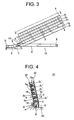
Fig. 4 ]
FIG. 4 is a front view showing the other embodiment of the present invention. -
FIGS. 1 to 3 show one embodiment of a component supply device and a component supply method in the present invention. - As shown in
FIG. 1 , acomponent supply device 1 is inclined forward and downward. Thecomponent supply device 1 has hollow sticks 2 (21-25) for receiving components which is laminated with multiple tiers, a plurality ofconnector housings 3 made of synthetic resin as the components received in each the stick 2, aweight ball 4 movably arranged next to the back end of thebottom connector housing 3 in each the stick 2 and made of metal such as stainless assisting falling of theconnector housing 3 at a slope of the stick 2, acomponent supply route 5 connecting to a front of the bottom stick 21 at a slant or curvature, a weightball collection route 6 intersecting with thecomponent supply route 5 close to the front end of the bottom stick 21 and inclined downward and backward, and a proximity sensor (weight detecting sensor) 7 for detecting the weight ball. Theproximity sensor 7 is arranged in a intersecting portion of thecomponent supply route 5 with the weightball collection route 6 or near the intersection portion. - Each of the stick 2 is made of synthetic resin material, formed in a rectangular rolled shape with a
bottom wall 8 laterally extending, bothside walls 9, and anupper wall 10, and hasopenings openings component receiving spaces 13 surrounded by thebottom wall 8, the bothside walls 9, and theupper wall 10. For this reason, the stick 2 is able to be used regardless of a position of the front and back thereof. Preferably, theupper wall 10 has a slit (not shown) of a longitudinal direction in the center of the width direction so as to look at the components. If a fall of theconnector housing 3 or theweight ball 4 have no worries, it is possible to eliminate theupper wall 10 and form the stick 2 in a concave shape of a cross-section. In addition, the stick 2 can be formed with metal material such as aluminum having a smoothly surface. - The
component receiving space 13 arranged in the stick 2 is formed wider than theconnector housing 3 in longitudinal and laterally directions, and slides and smoothly drops theconnector housing 3. The inclination angle when the stick 2 is horizontally positioned is 20° to 25° degree. Since theweight ball 4 is used, the component supply device is controlled with a relatively-gentle inclination so as to lower the height of the component supply device. The length of each stick 2 of the embodiment is a length which can receive theconnector housing 3, for example twentyconnector housings 3, in series. - For example, a worker holds the stick 2 with both hands, and inclines it forward and downward. In a case that the
opening 11 is blocked with his left hand, eachconnector housing 3 is inserted from theopening 12 arranged in the back end into the stick 2, and finally theweight ball 4 is inserted. Thereafter, the stick 2 in which theconnector housing 3 and theweight ball 4 are inserted is set to a device main body (not shown). - Furthermore, the
opening 12 of the back end may be narrowed against theweight ball 4 as a stopper. Further, a worker may hold and incline the stick 2 backward and downward, and insert theweight ball 4 and eachconnector housing 3 into the stick 2 from thewide opening 11 of the front end in order. The stick 2 may be called a rectangular tube body or component receiving tube. The shape of eachconnector housing 3 is the same size in a general rectangular shape. However, when a circular or trapezoidal connector housing is used, the stick 2 is formed in a tubular body according to the shape of theconnector housing 3. - The
weight ball 4 is a stainless-steel ball and heavier more than theconnector housing 3. Furthermore, the outer diameter of theweight ball 4 is formed smaller than the length of theconnector housing 3 in a longitudinal direction and the height thereof in a vertical direction. The outer diameter of theweight ball 4 may be the same as the width of theconnector housing 3 in a horizontal direction. Theweight ball 4 assists gravity feed of theconnector housing 3 along the inner surface of the inclined stick 2. - The device main body (not shown) includes a metallic frame, laminates each stick 2, and maintains an inclined state. The inclined
component supply route 5 is connected or projected in the front end of the frame. The frame has a bottom portion inclined along the bottom stick 21 ofFIG. 1 , and front and back wall portions inclined forward along the front and back ends of the stick 2. The frame has a bottom portion inclined along the bottom stick 21 (stick of bottom tier) ofFIG. 1 , and front and back wall portions inclined forward along the front and back ends of the stick 2. The front wall of the frame blocks thefront opening 11 of each stick 22-25 of more than the second tier, and prevents an escape of theconnector housing 3 from thefront opening 11. Each stick 2 can decline along the frame step by step by a lifting device (not shown) of an air cylinder of the device main body. A positioning holding of the stick 2 in the frame 2 is performed by a holding means (not shown). The device main body will be suggested in another application in detail. - In
FIG. 1 , the inclinedcomponent supply route 5 has asquare hole 14 for dropping the weight ball or opening on oneside wall 5a in a portion crossing the weightball collection route 6. The size of thehole 14 is set and formed smaller than the length of theconnector housing 3 and the height thereof so as to not catch or enter theconnector housing 3 in thehole 14. The lower end of thehole 14 is positioned in plane with the inner surface of the bottom wall 5b of thecomponent supply route 5, and apart 5a' of theside wall 5a of thecomponent supply route 5 remains at an upper side of the upper end of thehole 14. For this reason, the front end of theconnector housing 3 is not caught in thehole 14, and thereby theconnector housing 3 slide along thecomponent supply route 5 smoothly. - In
FIG. 1 , when the last connector housing 3e in the bottom stick 21 passes through thehole 14 as shown inFIG. 2 (when the back end surface of the last connector housing 3e is positioned in plane with the front end of the hole 14), theweight ball 4 of the bottom stick 21 is entered into thehole 14. In the bottom wall 5b of thecomponent supply route 5 connecting to the lower end of thehole 14, ainclined surface 15 for guiding the weight ball may be formed toward a opening (using reference number 14) of the weightball collection route 6 to a obliquely downward direction so as to reliably drop theweight ball 4 from thehole 14 to the lateral weightball collection route 6. - The width of the
inclined surface 15 in the longitudinal direction is the same as the width of thehole 14 in the longitudinal direction. Preferably, the width of theinclined surface 15 in the horizontal direction is smaller than the width of thecomponent supply route 5 in the horizontal direction so as to smoothly pass theconnector housing 3 through thecomponent supply route 5 without catching on an uneven surface occurring from theinclined surface 15. Thehole 14 is located at theside wall 5a of thecomponent supply route 5, but it is able to be located at the bottom wall 5b. - The weight
ball collection route 6 is connected to thehole 14 of thecomponent supply route 5, inclined in a direction opposite to a direction in which thecomponent supply route 5 is inclined at an angle much smaller than an inclination angle of the stick 2 (at a nearly-horizontal angle), and linearly extends from thehole 14 backward. The weightball collection route 6 is positioned in the lower side of either side of the stick 2 not under the stick 2 instead of just under the stick 2. Under the bottom stick 21 ofFIG. 1 , aspace 16 is arranged in the frame at one side of the weightball collection route 6 so as to move the used empty stick 2 down. - For example, the weight
ball collection route 6 is formed in U-shape in cross-section, the opening connected to thehole 14 is formed with a size being equal to or larger than thehole 14 in oneside wall 6a of the front end, and aopening 17 is arranged in theside wall 6a of the back end so as to discharge theweight ball 4 outside. When theopening 17 of the back end is not arranged, the weightball collection route 6 is removable type as well as the stick 2, and theweight ball 4 is collected by removing the weightball collection route 6 from the frame. The front end of the weightball collection route 6 is located in a little front from the front end of the bottom stick 21, and the back end of the weightball collection route 6 is located in the same virtual vertical plane as the back end of a top stick 25. - A
proximity sensor 7 is fixed to the front end (front wall) of the weightball collection route 6 at one side of thehole 14. A detectingsurface 7a arranged in the end of theproximity sensor 7 is located beside the front end of thehole 14, and thereby theweight ball 4 rolling out of the weightball collection route 6 from thehole 14 can be detected. - Preferably, the
proximity sensor 7 is a magnetic proximity sensor in response to themetallic weight ball 4. However, for example, when theweigh ball 4 is made of heavy non-metal, or when a resin layer is coated on the surface of themetallic weight ball 4, it is possible to use a capacitancetype proximity sensor 7. - A function of the
proximity sensor 7 is to detect that the bottom stick 21 become empty. In place of theproximity sensor 7, it is possible to use a light sensor or a lever contact-type on-off switch (sensor) and the like. Furthermore, an installation location of theproximity sensor 7 is not limited near thehole 14. Theproximity sensor 7 may be located in theside wall 6a of the weightball collection route 6 behind thehole 14. - When the
proximity sensor 7 is located midway in the weighball collection route 6, time lag might occur in detection. As a result, there is a worry that the detection ofupper weight ball 4 can not be performed when all theweight balls 4 are received in the weightball collection route 6. Thus, it is desirable that theproximity sensor 7 is located near thehole 14 as much as possible. Since theproximity sensor 7 is not arranged in thecomponent supply route 5, theconnector housing 3 passes thecomponent supply route 5 smoothly without causing interference with theproximity sensor 7. - The
component supply route 5 is formed in a U-shape in cross section with the curved bottom wall 5b and right and leftside walls 5a. For example, thecomponent supply route 5 is fixed in a vertical side wall 18 being a part of the frame. The back end of thecomponent supply route 5 is inclined, and communicates with theopening 11 of the front end of the bottom stick 21. That is, the back end of thecomponent supply route 5 abuts on the front end of the bottom stick 21. - A
front portion 5c of thecomponent supply route 5 is horizontally positioned. In thefront portion 5c, the right and leftside walls 5a is notched, and a notchedportion 19 is formed. In the notchedportion 19, the right and leftside walls 5a of theconnector housing 31 are exposed. In the notchedportion 19, for example, theconnector housing 31 is gripped with a chuck (not shown), lifted, and then transferred to next process. In the front end of thecomponent supply route 5, astopper wall 20 perpendicular to thefirst connector housing 31 is arranged. Theconnector housing 3 of the embodiment of the present invention is transferred to a terminal inserting process of next process in a state that the wide opening of a terminal receiving chamber is kept forward (a position that a terminal is inserted from the wide opening). The terminal with electric wire is inserted into theconnector housing 3, and the connector is constructed. - Action of the
component supply device 1, that is, a component supply method will be explained with reference toFIGS 1 to 3 below. - In an example of
FIG. 1 , the stick 2 in which theconnector housing 3 is inserted is laminated with five tiers. The laminated number of the stick 2 may be more than five steps if the frame of device main body becomes high.Several connector housings 3 in the bottom stick 21 are already sent to thecomponent supply route 5, and thefirst connector housing 31 abuts on thestopper wall 20 of the front end of thecomponent supply route 5. A sending operation of theconnector housing 3 in the stick 2 is performed by the weight of theconnector housing 3 and a force pressing theconnector housing 3 forward with the weight of theweight ball 4. A plurality ofconnector housings 3 are sent from the stick 21 to thestopper wall 20 of the front end of thecomponent supply route 5 in series in a state that the front end and the back end are closely connected to each other in the longitudinal direction. - In a state of
FIG. 1 , thefirst connector housing 31 is supplied to the next process with a chuck (not shown). At the same time, eachconnector housing 3 slides forward by the weight and the action of theweight ball 4, and theconnector housing 32 being second from the front abuts on thestopper wall 20. In the same manner, theconnector housing 3 is sent to the next process with the chuck one by one. Theweight ball 4 presses and abuts on a back end surface of the last connector housing 3e at all times. - As shown in
FIG. 2 , the bottom (first) stick 21 becomes empty, and theconnector housing 3 is positioned in thecomponent supply route 5 connected to the front of the bottom stick 21. The end of the connector housing 3e in thecomponent supply route 5 passes thehole 14 for collecting the weight ball, and theweight ball 4 is positioned in thehole 14 having contact with the back end of the end of the connector housing 3e. At the same time, theweight ball 4 rolls down from thehole 14 to the weightball collection route 6, simultaneously theproximity sensor 7 detects theweight ball 4, and information that bottom stick 21 is empty is transmitted to a control section (not shown). - The control section provides instructions to the lifting and lowering device (not shown) and a holding device (not shown) arranged in the device main body. As shown in
FIG. 3 , the lifting and lowering device lowers all the sticks 2 (21- 25) to one tier of the stick, and the stick 21 of the first tier emptied is moved down lower than thecomponent supply route 5. The holding device releases holding of the bottom stick 21, and is moved to acollection space 16 arranged in the lower side of the frame to drop the bottom stick 21. - The second stick 22 from the bottom in
FIG. 2 is the bottom stick inFIG. 3 , and theopening 11 arranged in the front end of the bottom stick 22 communicates with an opening arranged in the back end of thecomponent supply route 5. Theconnector housing 3 in the bottom stick 22 is sent to thecomponent supply route 5 by both the weight of theconnector housing 3 and pressing force of theweight ball 4. In anend space 5d of the emptycomponent supply route 5 inFIG. 2 ,new connector housing 3 is replenished. - As shown in
FIG. 3 , between the front end of thecomponent supply route 5 and theweight ball 4 arranged in the back portion of the bottom stick 22, eachconnector housing 3 is tightly positioned in the longitudinal direction in close contact with each other. The front end of theconnector housing 31 in thecomponent supply route 5 inFIG. 3 is conveyed to next process by a chuck. At the same time, theconnector housing 3 in the bottom stick 22 is pressed by theweight ball 4, and thereby moved toward thecomponent supply route 5. - In
FIG. 3 , when the bottom (second) stick 22 becomes empty after repeating movement ofFIGS. 1 and 2 , the bottom stick 22 falls into thecollection space 16 located in the bottom. In the same manner, the other three sticks 23 - 25 send theconnector housing 3 to thecomponent supply rout 5, and all of theconnector housings 3 are continuously supplied to next process. - When all of the sticks 2 (21- 25) have fell into the
collection space 16,several connector housing 3 remains in thecomponent supply route 5. However, by again laminating and arranging the stick 2 in which theconnector housing 3 is newly loaded in the frame, theconnector housing 3 of thecomponent supply route 5 is pressed forward in theconnector housing 3 of the bottom stick 21, and can be supplied to next process. Furthermore, the lastseveral connector housings 3 may be moved to the front end of thecomponent supply route 5 by a hand of a worker. - In the embodiment of
FIGS. 1-3 , the sizes of the stick 2 orcomponent supply route 5 can be changed based on the type or size of theconnector housing 3. However, as thecomponent supply device 21 shown inFIG. 4 , for example, by including each stick 2' (21' - 25') at an angle in a front vision, that is, by tilting each stick 2' in a circumferential direction, it is possible to correspond to various types or sizes of theconnector housing 3 being equal to or smaller than the cross-sectional shape of the stick 2'. - The
bottom wall 3a and oneside wall 3b of theconnector housing 3 are supported by both the inner surface of thebottom wall 8 of the stick 2' and the inner surface of eitherside wall 9. In common with the stick 2', thecomponent supply route 5 can be inclined in front vision and used. In this case, by inclining and using thecomponent supply device 1 ofFIG. 1 in whole, it is possible to perform. The cross-section of each stick 2' is formed larger than the cross-section of the connector housing 2. - In the embodiment of
FIG. 4 , thecomponent supply route 5 is bent from the bottom stick 21' in the front vision, and theconnector housing 31 is horizontally located in the front of thecomponent supply route 5. Theweight ball 4 rolls from the bottom stick 21' in a tilting direction of the stick 2' (the direction in which theconnector housing 3 is inclined by the own weight) in the front vision, and is collected in the weightball collection route 6 from theopening 14 of the side portion. - In
FIG. 4 , thereference number 10 indicates the upper wall of the stick, thereference number 10a indicates the slit in the center of the upper wall, thereference number 22 indicates the side wall of the frame, and thereference number 23 indicates the flat base of the frame. Furthermore, an illustration of thesensor 7 shown inFIG. 1 is not omitted. The structure shown inFIG. 4 is effective not only as thecomponent supply device 21 but also the component supply method. - Also, in each embodiment of
FIGS. 1 to 4 , the stick 2 is laminated with multiple tiers, however it is not limited. For example, a relatively low-volume production case may arrange stick 2 in one tier, supply theconnector housing 3 in the stick 2, and detect theweight ball 4 in the stick 2 by thesensor 4. At this time, according to the annunciation signal, the stick 2 can be pulled out by a worker, and the stick 2 in which new connector housing is inserted can be replaced. - In each embodiment, the
connector housing 3 is used as the component, but it is not limited thereto. For example, instead of theconnector housing 3, a connector receiving a terminal for crimping an electric wire, relay, or a box-shaped fusible link may be used. - The component supply device and the component supply method according to the present invention can be used to continuously supply the connector housing to a terminal inserting process one by one in a manufacturing process such as the wiring harness.
-
- 1, 21
- component supply device
- 2
- stick
- 2'
- stick
- 3
- connector housing (component)
- 3a
- bottom surface
- 3b
- one side surface
- 4
- weight ball
- 5
- component supply route
- 6
- weight ball collection route
- 7
- proximity sensor (sensor)
- 8
- bottom wall
- 9
- one side wall
- 14
- hole
Claims (5)
- A component supply device comprising:a stick continuously receiving a plurality of components, and inclined in a component supply direction, anda weight ball arranged in an end of the plurality of the components in the stick, and pressing the plurality of the components in the component supply direction.
- The component device as claimed in claim 1, further comprising a component supply route connected to the stick, a weight ball collection route connected to a hole for collecting the weight ball, the hole being arranged in the component supply route, and a sensor for detecting the weight ball, the sensor being arranged in the weight ball collection route.
- The component supply device as claimed in claim 2, further comprising a lifting and lowering device operated by a signal of the sensor,
wherein the stick receives the plurality of the components and the weight ball, and arranged with multiple tiers,
wherein the component supply route is connected to the stick of bottom tier, and
wherein the multiple tiers stick is lowered to one tier by the lifting and lowering device, the stick of the bottom tier emptied is removed from the component supply route, and the stick second from the bottom tier is connected to the component supply route. - The component supply device as claimed in claim 1, 2 or 3, wherein the stick is cross-sectionally rectangular-shaped and inclined in a circumferential direction of the stick so that a bottom surface of the component and one side surface of the component are supported with a bottom wall of the stick and one side wall of the stick, the cross-sectional surface of the stick is configured sufficiently larger than the cross-sectional surface of the component, and thereby the stick has general-purpose properties depending on the type of the component.
- A method for supplying components comprising the steps of:continuously receiving a plurality of components in a stick,arranging a weight ball in the end of the plurality of the components,arranging the stick with multiple tiers and inclining the multiple tiers stick in a component supply direction,arranging a component supply route connected to the bottom stick,crossing a weight ball collection route with the component supply route,arranging a sensor in the weight ball collection route,detecting the weight ball by the sensor,arranging a lifting and lowering device operated by a detecting signal of the sensor,lowering the multiple tiers stick to one tier by the lifting and lowering device based on the detecting signal of the sensor, andconnecting the second stick from the bottom to the component supply route.
Applications Claiming Priority (2)
| Application Number | Priority Date | Filing Date | Title |
|---|---|---|---|
| JP2010288336A JP5752407B2 (en) | 2010-12-24 | 2010-12-24 | Component supply apparatus and component supply method |
| PCT/JP2011/079800 WO2012086751A1 (en) | 2010-12-24 | 2011-12-22 | Component supply device and component supply method |
Publications (3)
| Publication Number | Publication Date |
|---|---|
| EP2657159A1 true EP2657159A1 (en) | 2013-10-30 |
| EP2657159A4 EP2657159A4 (en) | 2017-12-06 |
| EP2657159B1 EP2657159B1 (en) | 2019-02-27 |
Family
ID=46314018
Family Applications (1)
| Application Number | Title | Priority Date | Filing Date |
|---|---|---|---|
| EP11851741.6A Active EP2657159B1 (en) | 2010-12-24 | 2011-12-22 | Component supply device and component supply method |
Country Status (7)
| Country | Link |
|---|---|
| EP (1) | EP2657159B1 (en) |
| JP (1) | JP5752407B2 (en) |
| CN (1) | CN103282293B (en) |
| MX (1) | MX2013007246A (en) |
| PH (1) | PH12013501344A1 (en) |
| TR (1) | TR201907211T4 (en) |
| WO (1) | WO2012086751A1 (en) |
Families Citing this family (1)
| Publication number | Priority date | Publication date | Assignee | Title |
|---|---|---|---|---|
| JP6160918B2 (en) * | 2013-12-16 | 2017-07-12 | 青山 省司 | Parts supply unit integrated with parts feeder |
Family Cites Families (11)
| Publication number | Priority date | Publication date | Assignee | Title |
|---|---|---|---|---|
| US4488662A (en) * | 1982-11-18 | 1984-12-18 | At&T Technologies, Inc. | Magazining device for use with automatic component assembling machine |
| JPS63106216A (en) * | 1986-10-24 | 1988-05-11 | Hitachi Ltd | IC feeder |
| JPH0626980B2 (en) * | 1987-02-16 | 1994-04-13 | 三菱電機株式会社 | Empty stack collection device |
| GB2254604B (en) * | 1991-03-01 | 1995-03-29 | Peter Robert Heald | Merchandising system |
| JPH10224083A (en) * | 1997-02-07 | 1998-08-21 | Tamura Seisakusho Co Ltd | Automatic insertion stick |
| JP4439062B2 (en) * | 2000-01-18 | 2010-03-24 | 株式会社トーショー | Article storage device |
| JP4582846B2 (en) * | 2000-01-18 | 2010-11-17 | 株式会社トーショー | Chemical storage device |
| JP4462690B2 (en) * | 2000-01-18 | 2010-05-12 | 株式会社トーショー | Chemical storage device |
| JP4601115B2 (en) * | 2000-03-17 | 2010-12-22 | 株式会社トーショー | Drug cassette |
| JP2005280971A (en) * | 2004-03-31 | 2005-10-13 | Kumahira Safe Co Inc | Storage rack device |
| JP4611818B2 (en) | 2005-06-27 | 2011-01-12 | タイコエレクトロニクスジャパン合同会社 | Connector feeder |
-
2010
- 2010-12-24 JP JP2010288336A patent/JP5752407B2/en active Active
-
2011
- 2011-12-22 WO PCT/JP2011/079800 patent/WO2012086751A1/en not_active Ceased
- 2011-12-22 TR TR2019/07211T patent/TR201907211T4/en unknown
- 2011-12-22 MX MX2013007246A patent/MX2013007246A/en active IP Right Grant
- 2011-12-22 EP EP11851741.6A patent/EP2657159B1/en active Active
- 2011-12-22 PH PH1/2013/501344A patent/PH12013501344A1/en unknown
- 2011-12-22 CN CN201180062557.2A patent/CN103282293B/en active Active
Non-Patent Citations (1)
| Title |
|---|
| See references of WO2012086751A1 * |
Also Published As
| Publication number | Publication date |
|---|---|
| PH12013501344A1 (en) | 2013-08-28 |
| TR201907211T4 (en) | 2019-06-21 |
| JP5752407B2 (en) | 2015-07-22 |
| WO2012086751A1 (en) | 2012-06-28 |
| CN103282293A (en) | 2013-09-04 |
| MX2013007246A (en) | 2013-11-04 |
| CN103282293B (en) | 2015-09-30 |
| JP2012136303A (en) | 2012-07-19 |
| EP2657159B1 (en) | 2019-02-27 |
| EP2657159A4 (en) | 2017-12-06 |
Similar Documents
| Publication | Publication Date | Title |
|---|---|---|
| AT2841U1 (en) | PICKING SYSTEM | |
| CN102006947B (en) | Feeding device and method for bars | |
| CN103415966A (en) | Terminal insertion device, wire harness manufacturing device, article inspection device, terminal insertion method, wire harness manufacturing method, article inspection method | |
| KR101252037B1 (en) | Stud supply device for auto stud insert equipment | |
| EP0986508B1 (en) | Commissioning system with a high-speed automatic machine and a shelf control unit | |
| CN106465578A (en) | Component mounting device | |
| DE4023772C2 (en) | ||
| CN109262226B (en) | Novel automatic assembling machine for scattered end riveting carbon sheets | |
| EP2657159B1 (en) | Component supply device and component supply method | |
| JPH0952622A (en) | Feeding structure for part conveying tray | |
| EP1727413A1 (en) | A method for supplying a component, as well as a component supplying device | |
| EP2657157B1 (en) | Component housing stick replacement device and component housing stick replacement method | |
| CN102056471B (en) | The assembly supply device of electronic component mounting apparatus and parts supply method | |
| CN210681342U (en) | Platform that gathers materials of box assembly line is supplied to intelligence | |
| JP6453742B2 (en) | Soldering apparatus and soldering method | |
| CN107055054B (en) | Rivet directly shakes feeding mechanism | |
| CN108031654B (en) | Rod-shaped element screening mechanism | |
| KR101731776B1 (en) | Apparatus for feeding lectronic components | |
| CN222695362U (en) | Discharging device and sorting machine | |
| KR102788010B1 (en) | Auto shaft tapping machine | |
| CN114228249A (en) | Sticker device, control method of sticker device | |
| CN216187482U (en) | Cylinder workpiece conveying device | |
| JP7142209B2 (en) | Characteristic measuring device, component mounting device, characteristic measuring method, and component mounting method | |
| JP5623441B2 (en) | Parts supply device | |
| CN220049919U (en) | Material distributing device |
Legal Events
| Date | Code | Title | Description |
|---|---|---|---|
| PUAI | Public reference made under article 153(3) epc to a published international application that has entered the european phase |
Free format text: ORIGINAL CODE: 0009012 |
|
| 17P | Request for examination filed |
Effective date: 20130709 |
|
| AK | Designated contracting states |
Kind code of ref document: A1 Designated state(s): AL AT BE BG CH CY CZ DE DK EE ES FI FR GB GR HR HU IE IS IT LI LT LU LV MC MK MT NL NO PL PT RO RS SE SI SK SM TR |
|
| DAX | Request for extension of the european patent (deleted) | ||
| RA4 | Supplementary search report drawn up and despatched (corrected) |
Effective date: 20171107 |
|
| RIC1 | Information provided on ipc code assigned before grant |
Ipc: B65G 47/16 20060101AFI20171101BHEP |
|
| STAA | Information on the status of an ep patent application or granted ep patent |
Free format text: STATUS: EXAMINATION IS IN PROGRESS |
|
| REG | Reference to a national code |
Ref country code: DE Ref legal event code: R079 Ref document number: 602011056745 Country of ref document: DE Free format text: PREVIOUS MAIN CLASS: B65G0047160000 Ipc: B65G0047510000 |
|
| 17Q | First examination report despatched |
Effective date: 20180614 |
|
| RIC1 | Information provided on ipc code assigned before grant |
Ipc: B65G 47/51 20060101AFI20180717BHEP Ipc: H05K 13/00 20060101ALI20180717BHEP |
|
| GRAP | Despatch of communication of intention to grant a patent |
Free format text: ORIGINAL CODE: EPIDOSNIGR1 |
|
| STAA | Information on the status of an ep patent application or granted ep patent |
Free format text: STATUS: GRANT OF PATENT IS INTENDED |
|
| INTG | Intention to grant announced |
Effective date: 20180919 |
|
| GRAS | Grant fee paid |
Free format text: ORIGINAL CODE: EPIDOSNIGR3 |
|
| GRAA | (expected) grant |
Free format text: ORIGINAL CODE: 0009210 |
|
| STAA | Information on the status of an ep patent application or granted ep patent |
Free format text: STATUS: THE PATENT HAS BEEN GRANTED |
|
| AK | Designated contracting states |
Kind code of ref document: B1 Designated state(s): AL AT BE BG CH CY CZ DE DK EE ES FI FR GB GR HR HU IE IS IT LI LT LU LV MC MK MT NL NO PL PT RO RS SE SI SK SM TR |
|
| REG | Reference to a national code |
Ref country code: GB Ref legal event code: FG4D |
|
| REG | Reference to a national code |
Ref country code: CH Ref legal event code: EP |
|
| REG | Reference to a national code |
Ref country code: DE Ref legal event code: R096 Ref document number: 602011056745 Country of ref document: DE |
|
| REG | Reference to a national code |
Ref country code: AT Ref legal event code: REF Ref document number: 1100983 Country of ref document: AT Kind code of ref document: T Effective date: 20190315 |
|
| REG | Reference to a national code |
Ref country code: IE Ref legal event code: FG4D |
|
| REG | Reference to a national code |
Ref country code: RO Ref legal event code: EPE |
|
| REG | Reference to a national code |
Ref country code: NL Ref legal event code: MP Effective date: 20190227 |
|
| REG | Reference to a national code |
Ref country code: LT Ref legal event code: MG4D |
|
| PG25 | Lapsed in a contracting state [announced via postgrant information from national office to epo] |
Ref country code: SE Free format text: LAPSE BECAUSE OF FAILURE TO SUBMIT A TRANSLATION OF THE DESCRIPTION OR TO PAY THE FEE WITHIN THE PRESCRIBED TIME-LIMIT Effective date: 20190227 Ref country code: PT Free format text: LAPSE BECAUSE OF FAILURE TO SUBMIT A TRANSLATION OF THE DESCRIPTION OR TO PAY THE FEE WITHIN THE PRESCRIBED TIME-LIMIT Effective date: 20190627 Ref country code: NL Free format text: LAPSE BECAUSE OF FAILURE TO SUBMIT A TRANSLATION OF THE DESCRIPTION OR TO PAY THE FEE WITHIN THE PRESCRIBED TIME-LIMIT Effective date: 20190227 Ref country code: NO Free format text: LAPSE BECAUSE OF FAILURE TO SUBMIT A TRANSLATION OF THE DESCRIPTION OR TO PAY THE FEE WITHIN THE PRESCRIBED TIME-LIMIT Effective date: 20190527 Ref country code: FI Free format text: LAPSE BECAUSE OF FAILURE TO SUBMIT A TRANSLATION OF THE DESCRIPTION OR TO PAY THE FEE WITHIN THE PRESCRIBED TIME-LIMIT Effective date: 20190227 Ref country code: LT Free format text: LAPSE BECAUSE OF FAILURE TO SUBMIT A TRANSLATION OF THE DESCRIPTION OR TO PAY THE FEE WITHIN THE PRESCRIBED TIME-LIMIT Effective date: 20190227 |
|
| PG25 | Lapsed in a contracting state [announced via postgrant information from national office to epo] |
Ref country code: IS Free format text: LAPSE BECAUSE OF FAILURE TO SUBMIT A TRANSLATION OF THE DESCRIPTION OR TO PAY THE FEE WITHIN THE PRESCRIBED TIME-LIMIT Effective date: 20190627 Ref country code: BG Free format text: LAPSE BECAUSE OF FAILURE TO SUBMIT A TRANSLATION OF THE DESCRIPTION OR TO PAY THE FEE WITHIN THE PRESCRIBED TIME-LIMIT Effective date: 20190527 Ref country code: HR Free format text: LAPSE BECAUSE OF FAILURE TO SUBMIT A TRANSLATION OF THE DESCRIPTION OR TO PAY THE FEE WITHIN THE PRESCRIBED TIME-LIMIT Effective date: 20190227 Ref country code: GR Free format text: LAPSE BECAUSE OF FAILURE TO SUBMIT A TRANSLATION OF THE DESCRIPTION OR TO PAY THE FEE WITHIN THE PRESCRIBED TIME-LIMIT Effective date: 20190528 Ref country code: LV Free format text: LAPSE BECAUSE OF FAILURE TO SUBMIT A TRANSLATION OF THE DESCRIPTION OR TO PAY THE FEE WITHIN THE PRESCRIBED TIME-LIMIT Effective date: 20190227 Ref country code: RS Free format text: LAPSE BECAUSE OF FAILURE TO SUBMIT A TRANSLATION OF THE DESCRIPTION OR TO PAY THE FEE WITHIN THE PRESCRIBED TIME-LIMIT Effective date: 20190227 |
|
| REG | Reference to a national code |
Ref country code: AT Ref legal event code: MK05 Ref document number: 1100983 Country of ref document: AT Kind code of ref document: T Effective date: 20190227 |
|
| PG25 | Lapsed in a contracting state [announced via postgrant information from national office to epo] |
Ref country code: CZ Free format text: LAPSE BECAUSE OF FAILURE TO SUBMIT A TRANSLATION OF THE DESCRIPTION OR TO PAY THE FEE WITHIN THE PRESCRIBED TIME-LIMIT Effective date: 20190227 Ref country code: IT Free format text: LAPSE BECAUSE OF FAILURE TO SUBMIT A TRANSLATION OF THE DESCRIPTION OR TO PAY THE FEE WITHIN THE PRESCRIBED TIME-LIMIT Effective date: 20190227 Ref country code: ES Free format text: LAPSE BECAUSE OF FAILURE TO SUBMIT A TRANSLATION OF THE DESCRIPTION OR TO PAY THE FEE WITHIN THE PRESCRIBED TIME-LIMIT Effective date: 20190227 Ref country code: DK Free format text: LAPSE BECAUSE OF FAILURE TO SUBMIT A TRANSLATION OF THE DESCRIPTION OR TO PAY THE FEE WITHIN THE PRESCRIBED TIME-LIMIT Effective date: 20190227 Ref country code: EE Free format text: LAPSE BECAUSE OF FAILURE TO SUBMIT A TRANSLATION OF THE DESCRIPTION OR TO PAY THE FEE WITHIN THE PRESCRIBED TIME-LIMIT Effective date: 20190227 Ref country code: AL Free format text: LAPSE BECAUSE OF FAILURE TO SUBMIT A TRANSLATION OF THE DESCRIPTION OR TO PAY THE FEE WITHIN THE PRESCRIBED TIME-LIMIT Effective date: 20190227 Ref country code: SK Free format text: LAPSE BECAUSE OF FAILURE TO SUBMIT A TRANSLATION OF THE DESCRIPTION OR TO PAY THE FEE WITHIN THE PRESCRIBED TIME-LIMIT Effective date: 20190227 |
|
| REG | Reference to a national code |
Ref country code: DE Ref legal event code: R097 Ref document number: 602011056745 Country of ref document: DE |
|
| PG25 | Lapsed in a contracting state [announced via postgrant information from national office to epo] |
Ref country code: PL Free format text: LAPSE BECAUSE OF FAILURE TO SUBMIT A TRANSLATION OF THE DESCRIPTION OR TO PAY THE FEE WITHIN THE PRESCRIBED TIME-LIMIT Effective date: 20190227 Ref country code: SM Free format text: LAPSE BECAUSE OF FAILURE TO SUBMIT A TRANSLATION OF THE DESCRIPTION OR TO PAY THE FEE WITHIN THE PRESCRIBED TIME-LIMIT Effective date: 20190227 |
|
| PG25 | Lapsed in a contracting state [announced via postgrant information from national office to epo] |
Ref country code: AT Free format text: LAPSE BECAUSE OF FAILURE TO SUBMIT A TRANSLATION OF THE DESCRIPTION OR TO PAY THE FEE WITHIN THE PRESCRIBED TIME-LIMIT Effective date: 20190227 |
|
| PLBE | No opposition filed within time limit |
Free format text: ORIGINAL CODE: 0009261 |
|
| STAA | Information on the status of an ep patent application or granted ep patent |
Free format text: STATUS: NO OPPOSITION FILED WITHIN TIME LIMIT |
|
| 26N | No opposition filed |
Effective date: 20191128 |
|
| PG25 | Lapsed in a contracting state [announced via postgrant information from national office to epo] |
Ref country code: SI Free format text: LAPSE BECAUSE OF FAILURE TO SUBMIT A TRANSLATION OF THE DESCRIPTION OR TO PAY THE FEE WITHIN THE PRESCRIBED TIME-LIMIT Effective date: 20190227 |
|
| REG | Reference to a national code |
Ref country code: DE Ref legal event code: R119 Ref document number: 602011056745 Country of ref document: DE |
|
| REG | Reference to a national code |
Ref country code: CH Ref legal event code: PL |
|
| REG | Reference to a national code |
Ref country code: BE Ref legal event code: MM Effective date: 20191231 |
|
| PG25 | Lapsed in a contracting state [announced via postgrant information from national office to epo] |
Ref country code: MC Free format text: LAPSE BECAUSE OF FAILURE TO SUBMIT A TRANSLATION OF THE DESCRIPTION OR TO PAY THE FEE WITHIN THE PRESCRIBED TIME-LIMIT Effective date: 20190227 |
|
| GBPC | Gb: european patent ceased through non-payment of renewal fee |
Effective date: 20191222 |
|
| PG25 | Lapsed in a contracting state [announced via postgrant information from national office to epo] |
Ref country code: FR Free format text: LAPSE BECAUSE OF NON-PAYMENT OF DUE FEES Effective date: 20191231 Ref country code: DE Free format text: LAPSE BECAUSE OF NON-PAYMENT OF DUE FEES Effective date: 20200701 Ref country code: LU Free format text: LAPSE BECAUSE OF NON-PAYMENT OF DUE FEES Effective date: 20191222 Ref country code: IE Free format text: LAPSE BECAUSE OF NON-PAYMENT OF DUE FEES Effective date: 20191222 Ref country code: GB Free format text: LAPSE BECAUSE OF NON-PAYMENT OF DUE FEES Effective date: 20191222 |
|
| PG25 | Lapsed in a contracting state [announced via postgrant information from national office to epo] |
Ref country code: CH Free format text: LAPSE BECAUSE OF NON-PAYMENT OF DUE FEES Effective date: 20191231 Ref country code: BE Free format text: LAPSE BECAUSE OF NON-PAYMENT OF DUE FEES Effective date: 20191231 Ref country code: LI Free format text: LAPSE BECAUSE OF NON-PAYMENT OF DUE FEES Effective date: 20191231 |
|
| PG25 | Lapsed in a contracting state [announced via postgrant information from national office to epo] |
Ref country code: CY Free format text: LAPSE BECAUSE OF FAILURE TO SUBMIT A TRANSLATION OF THE DESCRIPTION OR TO PAY THE FEE WITHIN THE PRESCRIBED TIME-LIMIT Effective date: 20190227 |
|
| PG25 | Lapsed in a contracting state [announced via postgrant information from national office to epo] |
Ref country code: MT Free format text: LAPSE BECAUSE OF FAILURE TO SUBMIT A TRANSLATION OF THE DESCRIPTION OR TO PAY THE FEE WITHIN THE PRESCRIBED TIME-LIMIT Effective date: 20190227 Ref country code: HU Free format text: LAPSE BECAUSE OF FAILURE TO SUBMIT A TRANSLATION OF THE DESCRIPTION OR TO PAY THE FEE WITHIN THE PRESCRIBED TIME-LIMIT; INVALID AB INITIO Effective date: 20111222 |
|
| PG25 | Lapsed in a contracting state [announced via postgrant information from national office to epo] |
Ref country code: MK Free format text: LAPSE BECAUSE OF FAILURE TO SUBMIT A TRANSLATION OF THE DESCRIPTION OR TO PAY THE FEE WITHIN THE PRESCRIBED TIME-LIMIT Effective date: 20190227 |
|
| PGFP | Annual fee paid to national office [announced via postgrant information from national office to epo] |
Ref country code: TR Payment date: 20251219 Year of fee payment: 15 |
|
| PGFP | Annual fee paid to national office [announced via postgrant information from national office to epo] |
Ref country code: RO Payment date: 20251127 Year of fee payment: 15 |