EP2656773B1 - Capsule medical device guiding system and magnetic field generating apparatus - Google Patents
Capsule medical device guiding system and magnetic field generating apparatus Download PDFInfo
- Publication number
- EP2656773B1 EP2656773B1 EP12738850.2A EP12738850A EP2656773B1 EP 2656773 B1 EP2656773 B1 EP 2656773B1 EP 12738850 A EP12738850 A EP 12738850A EP 2656773 B1 EP2656773 B1 EP 2656773B1
- Authority
- EP
- European Patent Office
- Prior art keywords
- magnetic field
- medical device
- capsule medical
- capsule endoscope
- vertical axis
- Prior art date
- Legal status (The legal status is an assumption and is not a legal conclusion. Google has not performed a legal analysis and makes no representation as to the accuracy of the status listed.)
- Not-in-force
Links
Images


Classifications
-
- A—HUMAN NECESSITIES
- A61—MEDICAL OR VETERINARY SCIENCE; HYGIENE
- A61B—DIAGNOSIS; SURGERY; IDENTIFICATION
- A61B1/00—Instruments for performing medical examinations of the interior of cavities or tubes of the body by visual or photographical inspection, e.g. endoscopes; Illuminating arrangements therefor
- A61B1/00147—Holding or positioning arrangements
- A61B1/00158—Holding or positioning arrangements using magnetic field
-
- A—HUMAN NECESSITIES
- A61—MEDICAL OR VETERINARY SCIENCE; HYGIENE
- A61B—DIAGNOSIS; SURGERY; IDENTIFICATION
- A61B1/00—Instruments for performing medical examinations of the interior of cavities or tubes of the body by visual or photographical inspection, e.g. endoscopes; Illuminating arrangements therefor
- A61B1/00002—Operational features of endoscopes
- A61B1/00043—Operational features of endoscopes provided with output arrangements
- A61B1/00045—Display arrangement
- A61B1/0005—Display arrangement combining images e.g. side-by-side, superimposed or tiled
-
- A—HUMAN NECESSITIES
- A61—MEDICAL OR VETERINARY SCIENCE; HYGIENE
- A61B—DIAGNOSIS; SURGERY; IDENTIFICATION
- A61B1/00—Instruments for performing medical examinations of the interior of cavities or tubes of the body by visual or photographical inspection, e.g. endoscopes; Illuminating arrangements therefor
- A61B1/04—Instruments for performing medical examinations of the interior of cavities or tubes of the body by visual or photographical inspection, e.g. endoscopes; Illuminating arrangements therefor combined with photographic or television appliances
- A61B1/041—Capsule endoscopes for imaging
Definitions
- the present invention relates to a capsule medical device guiding system for guiding a capsule medical device, which is introduced into a liquid in a subject and equipped with a permanent magnet, and a magnetic field generating device for generating a magnetic field for the capsule medical device.
- capsule endoscopes that include an imaging function and a wireless communication function in a capsule-shaped casing having a size introducible into an alimentary canal of a subject such as a patient have been developed.
- a capsule endoscope is swallowed through the mouth of a subject, and then is moved in the alimentary canal through peristaltic movement.
- the capsule endoscope sequentially acquires images (hereinafter, also referred to as in-vivo images) of internal organs of a subject, and wirelessly transmits the acquired in-vivo images to a receiving device outside the subject in sequence, during a time period until the capsule endoscope is excreted to the outside of the subject after being introduced into the alimentary canal of the subject.
- the in-vivo images captured by the capsule endoscope are input to an image display unit via the receiving device.
- the image display unit displays the input in-vivo images on a display in the form of still images or moving images.
- a user such as a doctor or a nurse observes various in-vivo images of the subject displayed on the image display unit, and examines the internal organs of the subject through observation of the in-vivo images.
- the capsule endoscope further includes a permanent magnet within a capsule-shaped casing, and an image display unit displays various in-vivo images sequentially captured by the capsule endoscope within the subject in real time.
- the guiding system of the capsule endoscope applies a magnetic field for the capsule endoscope within the subject, and magnetically guides the capsule endoscope within the subject to a desired location due to a magnetic attracting force received by the applied magnetic field.
- the user manipulates magnetic guidance of the capsule endoscope by using a manipulation input unit of the system while referring to the in-vivo images displayed on the image display unit.
- a magnetic guiding system for a capsule endoscope which applies a rotating magnetic field for rotating about a horizontal axis center of a long axis of the capsule endoscope and reciprocally rotates the capsule endoscope about the horizontal axis center of the long axis, in order to submerge the capsule endoscope located on a liquid surface into a liquid against a surface tension of the liquid surface has been suggested (see Patent Literature 1, for example). Further, a technology of applying a magnetic field for pivoting a capsule endoscope in a long axis direction of the capsule endoscope while rotating the capsule endoscope about a long axis of the capsule endoscope has been suggested (see Patent Literature 2, for example).
- Document EP 2 143 371 A1 on which document is based the preamble of claims 1 and 9, relates to a system for magnetically guiding a capsule medical device introduced into an organ of a subject such as a patient.
- a system for guiding capsule medical device according to a sixth embodiment allows a temporal swaying motion of a capsule medical device by an applied magnetic field before magnetically guiding the capsule medical device in a state floating on a liquid surface downward from the liquid surface, thereby eliminating the effect of surface tension of a liquid surface on the capsule medical device.
- the system for guiding capsule medical device includes a control device with a controller.
- the controller controls a magnetic field generator to generate an elimination magnetic field to eliminate the effect of surface tension of a liquid surface on the capsule medical device, wherein the elimination magnetic field is a rotating magnetic field reciprocally rotating around the horizontal axis at a predetermined rotation frequency and is applied to the capsule medical device aside from a guidance magnetic field control by the controller.
- Document US 2010/0307517 A1 relates to a medical device control system.
- a magnetic field is generated around a capsule endoscope.
- the jiggling mode has a magnetic field change pattern that swingably rotates the capsule endoscope corresponding to a jiggling switch of an operation unit, wherein the magnetic field is generated by combining an oscillating magnetic field for oscillating the intensity of the magnetic field and a revolving magnetic field that revolves in one direction on a revolving magnetic field plane, which is in substantially the same direction as that of a rotating axis, about which the capsule endoscope rotates around.
- the present invention has been made in view of the forgoing, and an object of the present invention is to provide a capsule medical device guiding system and a magnetic field generating device that allow the capsule medical device, which is constrained on a liquid surface, to be smoothly submerged into the liquid.
- a capsule medical device includes a permanent magnet and is configured to be introduced into a liquid in a subject; a magnetic field generating unit configured to generate a magnetic field to be applied to the permanent magnet to guide the capsule medical device, and configured to change a direction of the generated magnetic field in a three-dimensional space; and a control unit configured to cause the magnetic field generating unit to generate a variable magnetic field including a direction varying magnetic field whose magnetic field direction varies periodically on a plane whose direction changes periodically about a vertical axis and which is other than a horizontal plane, and a magnetic field for generating a magnetic attracting force for moving the capsule endoscope vertically downward.
- the direction varying magnetic field periodically changes each of an angle, which is between a long axis of the capsule medical device and the vertical axis, and an angle, which is between a predetermined reference plane passing through the vertical axis and a plane passing through the long axis of the capsule medical device and the vertical axis.
- the direction varying magnetic field generates a magnetic attracting force which makes an angle between a long axis of the capsule medical device and the vertical axis equal to or larger than 90°.
- the direction varying magnetic field is a rotating magnetic field whose magnetic field direction is periodically rotated on the plane, and the plane pivots about the vertical axis.
- the capsule medical device is configured to move in a liquid introduced into the subject, and has substantially a same density as a density of the liquid introduced into the subject.
- the permanent magnet has a magnetization in a direction parallel to a long axis of the capsule medical device.
- the capsule medical device guiding system of an embodiment of the invention there is at least timing at which the direction varying magnetic field faces a horizontal direction.
- the permanent magnet has a magnetization in a direction crossing a long axis of the capsule medical device, and a gravity center location of the capsule medical device is a location which is deviated from a geometric center of the capsule medical device in a direction different from the magnetization of the permanent magnet.
- the permanent magnet has a magnetization in a direction perpendicular to the long axis of the capsule medical device, and there is at least timing at which the direction varying magnetic field faces a vertical direction.
- a change period of the direction of the plane about the vertical axis is longer than a change period of a direction of the direction varying magnetic field on the plane.
- a magnetic field generating device is a magnetic field generating device for generating a magnetic field for a capsule medical device including a permanent magnet.
- the magnetic field generating device includes: a magnetic field generating unit configured to generate a magnetic field to be applied to the permanent magnet to guide the capsule medical device, and configured to change a direction of the generated magnetic field in a three-dimensional space; and a control unit configured to cause the magnetic field generating unit to generate a variable magnetic field including a direction varying magnetic field whose magnetic field direction varies periodically on a plane whose direction changes periodically about a vertical axis and which is other than a horizontal plane, and a magnetic field for generating a magnetic attracting force for moving the capsule endoscope vertically downward.
- a variable magnetic field is generated to be applied to a permanent magnet of a capsule medical device.
- the variable magnetic field includes a direction varying magnetic field whose magnetic field direction varies periodically on an arbitrary plane whose direction changes periodically about a vertical axis and which is other than a horizontal plane, and a magnetic field for generating a magnetic attracting force for moving the capsule medical device vertically downward. Therefore, the capsule medical device can be always pulled vertically downward while rotating toward various directions, and thus the capsule medical device can be released from constraint due to surface tension of a liquid surface and be smoothly submerged into the liquid.
- a guiding system for a capsule endoscope which uses a capsule endoscope introduced into an oral of a subject and floating in a liquid accumulated on a stomach of the subject will be described as an example.
- the present invention is not limited thereto, but may use various capsule medical devices such as, for example, a capsule endoscope moving in a lumen from the gullet of a subject along the anal or a capsule endoscope introduced from the anal together with an isotonic solution.
- the same reference numerals denote the same parts.
- FIG. 1 is a schematic diagram illustrating an entire configuration of a capsule medical device guiding system according to a first embodiment of the present invention.
- a capsule medical device guiding system 1 includes a capsule endoscope 10 which is a capsule medical device swallowed through the mouth of a subject to be introduced into a body cavity in the subject and configured to communicate with an external device, a magnetic field generating unit 2 provided around the subject and configured to generate a three-dimensional magnetic field, a transmitting/receiving unit 3 configured to perform a wireless communication with the capsule endoscope 10 and configured to receive a wireless signal containing an image captured by the capsule endoscope 10 and transmit a manipulation signal for the capsule endoscope 10, a control unit 4 configured to control various constituent elements of the capsule medical device guiding system 1, a display unit 5 configured to display and output the image captured by the capsule endoscope 10, an input unit 6 configured to input instruction information for instructing various manipulations in the capsule medical device guiding system 1, a manipulation input unit 7 configured to input guidance instructing information for magnetically guiding the capsule endoscope 10, a storage unit 8 configured to store image information captured by the capsule endoscope 10,
- the capsule endoscope 10 is a capsule medical device configured to acquire an in-vivo image of a subject, and employs an imaging function and a wireless communication function therein. After being introduced into an internal organ of a subject together with a specific liquid through an oral ingestion, the capsule endoscope 10 is moved through the interior of an alimentary canal and is finally excreted to the outside of the subject. The capsule endoscope 10 sequentially captures in-vivo images in the subject, and sequentially wirelessly transmits the obtained in-vivo images to the external transmitting/receiving unit 3. Further, the capsule endoscope 10 employs a magnetic body such as a permanent magnet therein. The capsule endoscope 10 drifts in the liquid introduced into an interior of an alimentary canal (for example, an interior of a stomach) of the subject, and is moved in the liquid while being magnetically guided by the external magnetic field generating unit 2.
- FIG. 2 is a sectional schematic diagram illustrating an exemplary configuration of the capsule endoscope illustrated in FIG. 1 .
- the capsule endoscope 10 includes a first imaging unit 11A, a second imaging unit 11B, a capsule-shaped casing 12, a processing unit 15, a transmitting unit 16, a power source 18, and a permanent magnet 19.
- the first imaging unit 11A and the second imaging unit 11B have an illumination system such as an LED, an optical system such as a condenser lens, and an imaging element such as a CMOS image sensor or a CCD, respectively, and capture images of a subject in different imaging directions.
- the capsule-shaped casing 12 is an external body formed to have a size easily introducible into the interior of an alimentary canal of a subject, and is configured such that opposite opening ends of a substantially opaque colored tubular casing 12a are blocked by dome-shaped transparent casings 12b and 12c.
- the capsule endoscope 10 is a two-lens capsule medical device for capturing a front side and a rear side in a direction of a long axis La
- the optical axes of the first imaging unit 11A and the second imaging unit 11B are substantially parallel to or substantially the same as the long axis La which is a lengthwise center axis of the capsule-shaped casing 12.
- the processing unit 15 performs various processing such as noise removing processing or amplifying processing for various images captured by the first imaging unit 11A and the second imaging unit 11B.
- the transmitting unit 16 generates a wireless signal obtained by modulating an image signal containing various images processed by the processing unit 15, and transmits the wireless signal to the external transmitting/receiving unit 3 via an antenna (not illustrated).
- the power source 18 has an accumulating unit such as a button type battery or a capacitor and a switch unit such as a magnetic switch, and supplies electric power to the constituent elements of the capsule endoscope 10.
- the permanent magnet 19 is for enabling a magnetic guidance by the magnetic field generating unit 2, and is fixedly disposed within the capsule-shaped casing 12.
- the magnetic field generating unit 2 is for magnetically guiding the capsule endoscope 10 in the subject.
- the magnetic field generating unit 2 is realized by using, for example, a plurality of coils, and generates a guiding magnetic field by using electric power supplied by an electric power supply unit (not shown).
- the magnetic field generating unit 2 applies the generated guiding magnetic field to a magnetic body in the capsule endoscope 10, and magnetically captures the capsule endoscope 10 through an operation of the guiding magnetic field.
- the magnetic field generating unit 2 may change a direction of the generated magnetic field in a three-dimensional space.
- the magnetic field generating unit 2 changes a magnetic field direction of the guiding magnetic field applied to the capsule endoscope 10 in the subject to control a three-dimensional posture of the capsule endoscope 10 in the subject.
- the transmitting/receiving unit 3 includes a plurality of antennas 3a, and receives in-vivo images of the subject from the capsule endoscope 10 via the plurality of antennas 3a.
- the transmitting/receiving unit 3 sequentially receives wireless signals from the capsule endoscope 10 via the plurality of antennas 3a.
- the transmitting/receiving unit 3 selects an antenna having the highest received magnetic field intensity among the plurality of antennas 3a, and performs demodulating processing on the wireless signals from the capsule endoscope 10 received via the selected antenna. Accordingly, the transmitting/receiving unit 3 extracts image data by the capsule endoscope 10, that is, in-vivo image data of the subject from the wireless signal.
- the transmitting/receiving unit 3 transmits image signals containing the extracted in-vivo image data to the control unit 4.
- the control unit 4 controls operations of the magnetic field generating unit 2, the transmitting/receiving unit 3, the display unit 5, and the storage unit 8, and controls input/output of signals between the constituent elements.
- the control unit 4 controls the storage unit 8 to store the in-vivo image group of the subject acquired from the transmitting/receiving unit 3.
- the control unit 4 includes an image receiving unit 41 configured to sequentially acquire the in-vivo images sequentially received by the transmitting/receiving unit 3, an image display controller 42 configured to display the in-vivo images sequentially received by the transmitting/receiving unit 3 on the display unit 5 in real time, and a magnetic field controller 43 configured to control the magnetic field generating unit 2 to guide the capsule endoscope 10.
- the magnetic field controller 43 controls an amount of current flowed to the magnetic field generating unit 2, and controls the magnetic field generating unit 2 to generate a guiding magnetic field necessary for magnetic guidance of the capsule endoscope 10 according to a magnetic guidance direction and a magnetic guidance location based on guidance instructing information.
- the display unit 5 is realized by using various displays such as a liquid crystal monitor, and displays various information instructed to display by the control unit 4.
- the display unit 5 displays, for example, an in-vivo image group of the subject captured by the capsule endoscope 10, based on the control of the image display controller 42 in the control unit 4. Further, the display unit 5 displays reduced images of the in-vivo images selected or marked through an input manipulation of the input unit 6 among the in-vivo image group, and patient information and examination information of the subject.
- the input unit 6 is realized by using an input device such as a keyboard and a mouse, and inputs various information to the control unit 4 according to an input manipulation by a user such as a doctor.
- the various information input to the control unit 4 by the input unit 6 may include, for example, instruction information instructed to the control unit 4, and patient information and examination information of the subject.
- the patient information of the subject is specific information specifying the subject, and includes, for example, a patent name, a patent ID, a birth date, a gender, and an age of the subject.
- the examination information of the subject is specific information specifying an examination for introducing the capsule endoscope 10 into the interior of the alimentary canal of the subject and observing the interior of the alimentary canal, and includes, for example, an examination ID and an examination date.
- Guidance instructing information for magnetically guiding the capsule endoscope 10 is input to the manipulation input unit 7.
- the manipulation input unit 7 inputs guidance instructing information for magnetically guiding the capsule endoscope 10, which is a magnetic guidance manipulated object, to the control unit 4.
- the guidance instructing information is for instructing a posture or a location of the capsule endoscope 10.
- the magnetic field controller 43 generates a magnetic field corresponding to the guidance instructing information in the magnetic field generating unit 2.
- the manipulation input unit 7 has configurations including a joystick, various buttons, and various switches, and inputs the guidance instructing information to the control unit 4 as the joystick is manipulated by a user.
- the manipulation input unit 7 is configured as a manipulation input unit including two joysticks 71 and 72.
- the joysticks 71 and 72 are used to three-dimensionally manipulate the capsule endoscope 10 through magnetic guidance, and may be tilted to the upper side, lower side, left side, and right side of the paper.
- an up button 73U and a down button 73B are provided on a rear surface of the joystick 71.
- FIG. 4 is a view where the capsule endoscope 10 is viewed from a direction perpendicular to a vertical axis, and exemplifies that the capsule endoscope 10 is located within the stomach St. Further, the density of the capsule endoscope 10 is set to be substantially the same as the density of a liquid W introduced into the subject. FIG. 4 exemplifies that the capsule endoscope 10 is located on the liquid surface Ws of the liquid W.
- the storage unit 8 is realized by using a storage medium, such as flash memory or a hard disk, for rewritably preserving information.
- the storage unit 8 stores various information instructed to store by the control unit 4, and delivers information instructed to be read out by the control unit 4 in the stored information to the control unit 4.
- the various information stored by the storage unit 8 may include, for example, various image data of the in-vivo image group of the subject captured by the capsule endoscope 10, data of the in-vivo images selected through the input manipulation of the input unit 6 among the in-vivo images displayed on the display unit 5, and input information by the input unit 6 such as patient information of the subject.
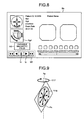
- the variable magnetic field generation instructing unit 9 includes a variable magnetic field button 91 in the manipulation input unit illustrated in FIGS. 3A and 3B , and when the variable magnetic field button 91 is pressed as indicated by an arrow Y6 (see FIG. 3B ), variable magnetic field instructing information for instructing generation of a variable magnetic field is input to the control unit 4. While the variable magnetic field instructing information is input, the magnetic field controller 43 generates a variable magnetic field for moving the capsule endoscope 10 restricted on a liquid surface into a liquid in the magnetic field generating unit 2.
- FIGS. 5A and 5B illustrate views of a variable magnetic field generated by the magnetic field generating unit 2.
- the variable magnetic field includes a rotating magnetic field where a direction of the magnetic field is rotated as indicated by the arrow Y16 on a plane Pv parallel to a vertical axis Az, and a magnetic field for generating a magnetic attracting force for moving the permanent magnet 19 in a downward direction of the vertical axis Az as indicated by an arrow Y18.
- the magnetic field rotating on the plane Pv is pivoted about the vertical axis Az while rotating.
- the rotating magnetic field is a magnetic field having an intensity, by which the capsule endoscope 10 can be moved, and a direction rotating about an arbitrary point of the plane Pv at a predetermined period as indicated by arrows Mr11, Mr12, and Mr13.
- the magnetic field for generating the magnetic attracting force in the vertically downward direction is set, for example, such that an intensity thereof becomes stronger toward a lower side from an upper side of the vertical axis Az.
- the magnetic field generating unit 2 generates a magnetic field such that the plane Pv is pivoted about the vertical axis Az at a predetermined period.
- the plane Pv is pivoted about the vertical axis Az as indicated by an arrow Y17a of FIG. 5B until a predetermined time elapses from the state illustrated in FIG. 5A .
- the pivot period of the plane Pv about the vertical axis Az is set to be sufficiently longer than a rotation period on the plane Pv of the rotating magnetic field so that the pivot of the plane Pv about the vertical axis Az does not influence the rotation of the rotating magnetic field.
- FIG. 6 is a view illustrating an operation of the capsule endoscope when a variable magnetic field is generated.
- FIG. 6 is a view where the capsule endoscope 10 is viewed from a direction perpendicular to the vertical axis Az.
- a magnetic attracting force for rotating the capsule endoscope 10 about a center of the long axis of the capsule endoscope 10 and a magnetic attracting force for moving the capsule endoscope 10 vertically downward as indicated by an arrow Y20 are generated at the same time. For this reason, the capsule endoscope 10 is pulled vertically downward while rotating on a plane parallel to the plane Pv.
- the rotation plane in which the capsule endoscope 10 is rotated is also pivoted about the vertical axis Az.
- a rotation direction of the capsule endoscope 10 is varied in response to the pivot of the rotation plane.
- the capsule endoscope 10 may be rotated in various directions, and thus the capsule endoscope 10 is apt to deviate from the restriction of a surface tension as compared with the case where a rotating operation is performed only in one direction.
- the capsule endoscope 10 even when an obstacle such as a stomach wall exists, as a variable magnetic field is generated, the rotation plane in which the capsule endoscope 10 is rotated is periodically pivoted by itself, and thus when the rotation plane is rotated in a direction deviating from the obstacle, the capsule endoscope 10 may be moved in a direction where the capsule endoscope 10 is not hindered by the obstacle. For this reason, in the first embodiment, even when an obstacle exists, the capsule endoscope 10 may be moved in a direction deviating from the obstacle, and a problem in that the capsule endoscope 10 may be hampered by an obstacle so as not to perform a rotating operation and the capsule endoscope 10 may not be moved can be solved.
- the capsule endoscope 10 may be always pulled vertically downward while rotating toward various directions, and thus the capsule endoscope 10 can be released from the restriction of a surface tension of a liquid surface and be smoothly submerged into the liquid.
- the movement of the capsule endoscope 10 is realized by combination of rotating magnetic fields of a power source having a low load, by which a magnetic field is smoothly varied, and thus a power source in the capsule medical device guiding system 1 can be miniaturized.
- the magnetization Ym of the permanent magnet 19 is parallel to the long axis La of the capsule endoscope 10, and the capsule endoscope 10 is rotated such that the direction of the long axis La coincides with the direction of the rotating magnetic field while the variable magnetic field is generated, and thus the capsule endoscope 10 is efficiently rotated with respect to the rotating magnetic field. For this reason, in the first embodiment, a marginal value of a magnetic field intensity of the rotating magnetic field may become small.
- the magnetic field generating unit 2 generates a variable magnetic field according to variable magnetic field instructing information
- a purpose of selecting a variable magnetic field is displayed on the display unit 5, and thus a manipulator is notified of generation of a variable magnetic field.
- the display unit 5 displays a menu Sa displaying a variable magnetic field icon Ic for notifying generation of a variable magnetic field on a left lower side, on the display screen.
- the variable magnetic field icon Ic is displayed by a bright color while the magnetic field generating unit 2 generates a variable magnetic field, and is displayed by a dark color while the magnetic field generating unit 2 stops generating a variable magnetic field.
- Various subject information such as a patient name, a patient ID, a birth date, a gender, and an age of a subject is displayed in an area S1 on the left upper side of the menu Sa.
- a living body image Sg1 captured by the imaging unit 11A is displayed on the left side and a living body image Sg2 captured by the imaging unit 11B is displayed on the right side.
- an area S3 below the area S2 of the menu Sa the captured images are reduced and displayed together with a capture time.
- a posture diagram Sg3 in a horizontal plane and a posture diagram Sg4 in a vertical plane are displayed as posture diagrams of the capsule endoscope 10.
- the postures of the capsule endoscope 10 displayed on the posture diagrams Sg3 and Sg4 display postures corresponding to guidance instructing information of the manipulation input unit 7.
- a direction in which the capsule endoscope 10 can be guided is indicated by an arrow.
- the generation states of the variable magnetic field during guidance of the capsule endoscope 10 may be preserved to correspond to the images, respectively.
- it may be recognized whether the capsule endoscope 10 is guided with a variable magnetic field when the playback image is acquired, by displaying the variable magnetic field icon Icb representing generation of a variable magnetic field corresponding to the playback image on the left lower side of the menu Sb together with the playback image in the playback menu Sb (see FIG. 8 ).
- an icon Ip for instructing playback of an image or an icon Is for temporary stop is displayed.
- a rotating magnetic field for continuously rotating a direction of a magnetic field in the plane Pv parallel to the vertical axis Az has been described to be included as a variable magnetic field, as long as a rotating magnetic field capable of rotating the capsule endoscope 10 about a center of a long axis of the capsule endoscope 10 is included, a variable magnetic field including a direction varying magnetic field which periodically varies a direction of a magnetic field on a plane Pv may be used.
- a direction of a magnetic field having an intensity by which the capsule endoscope 10 is movable is changed to a direction of an arrow Mr11 (see FIGS. 5A and 5B ) at a time t1, is changed to a direction of an arrow Mr12 (see FIGS. 5A and 5B ) at a time t2 after lapse of a predetermined time from the time t1, and is changed to a direction of an arrow Mr13 (see FIGS. 5A and 5B ) at a time t3 after lapse of a predetermined time from the time t2.
- the capsule endoscope 10 may also be periodically rotated in a plane parallel to the plane Pv about a center of the long axis of the capsule endoscope 10 according to a direction of the changed magnetic field.
- a variable magnetic field including a direction varying magnetic field for periodically changing a direction of a magnetic field in the plane Pv pivoting about the vertical axis Az an angle between the long axis La of the capsule endoscope 10 and the vertical axis Az can be periodically changed and an angle between a reference plane (for example, a plane located in the plane Pv illustrated in FIG. 5A ) passing through the vertical axis Az and a plane through which the long axis La of the capsule endoscope 10 and the vertical axis Az pass can also be periodically changed.
- a reference plane for example, a plane located in the plane Pv illustrated in FIG. 5A
- the plane Pv which is a rotation plane of a rotating magnetic field about the vertical axis Az at a predetermined period
- a rotation plane of the rotating magnetic field may be a plane other the horizontal plane.
- the plane Ps which is a plane crossing the vertical axis Az illustrated in FIG. 9 may be set to the rotation plane of the rotating magnetic field.
- the plane Ps is also controlled by the magnetic field controller 43 such that a direction thereof is periodically changed about the vertical axis Az.
- the present invention is not limited thereto. It is sufficient only if the capsule endoscope 10 repeats a posture where at least the long axis La of the capsule endoscope 10 and the vertical axis Az are perpendicular to each other in a plane parallel to the plane Pv such that the capsule endoscope 10 is operated to be significantly swung about the vertical axis Az. As illustrated in FIG.
- the magnetization Ym of the permanent magnet 19 is parallel to the long axis La of the capsule endoscope 10, and thus there is a need to generate a direction varying magnetic field having a timing facing at least the horizontal direction such that the capsule endoscope 10 takes a posture where the long axis La is perpendicular to the vertical axis Az.
- a magnetic field for changing a direction of a magnetic field to a plurality of directions containing at least the horizontal direction is set as a direction varying magnetic field. That is, it is sufficient only if a direction varying magnetic field is set to contain a magnetic field facing 0° or 180° with reference to the vertically upward direction.
- a direction of a magnetic field as the direction varying magnetic field may be set to be changed to the clockwise direction or the counterclockwise direction such that, as indicated by an arrow Y16a of FIG. 10 , the direction of the magnetic field forms an angle of -45° to 225° with respect to the vertical axis Az.
- a direction of a magnetic field may be set to be changed to the clockwise direction or the counterclockwise direction such that, as indicated by an arrow Y16b of FIG. 11 , the direction of the magnetic field forms an angle of 90° to 225° with respect to the vertical axis Az.
- a direction of a magnetic field may be set to be changed to the clockwise direction or the counterclockwise direction such that, as indicated by an arrow Y16c of FIG. 12 , the direction of the magnetic field forms an angle of 0° to 180° with respect to the vertical axis Az.
- a variable magnetic field including the direction varying magnetic field is generated, a magnetic attracting force by which an angle between the long axis La and the vertical axis Az of the capsule endoscope 10 is equal to or larger than 90° may be generated, and the capsule endoscope 10 may be released from the restriction of the surface tension while being significantly shaken about the vertical axis Az.
- a desired variable magnetic field may be selected from a plurality of variable magnetic fields including the above-described direction varying magnetic fields.
- the manipulator may select a desired variable magnetic field from the two variable magnetic fields through manipulation of the input unit 6.
- the type of the selected variable magnetic field is displayed in a variable magnetic field icon Ic1 of the menu Sc illustrated in FIG. 13 .
- the variable magnetic field icon Ic1 of FIG. 13 exemplifies a case of selecting a variable magnetic field 1 when the variable magnetic field 1 and a variable magnetic field 2 are set.
- the display of the variable magnetic field icon Ic1 is changed to a display where the variable magnetic field 2 is displayed.
- a magnetic attracting force for moving the capsule endoscope 10 vertically downward may become small as compared with the case where a density of the capsule endoscope 10 is smaller than a density of the liquid W introduced into the subject, by setting the density of the capsule endoscope 10 to be substantially the same as the density of the liquid W.
- an amount of energy supplied to generate a magnetic field in the magnetic field generating unit 2 becomes small and a load of the power source of the capsule medical device guiding system 1 becomes lower, and thus the power source can be miniaturized.
- FIG. 14 is a schematic diagram illustrating an entire configuration of a capsule medical device guiding system according to the second embodiment.
- a capsule medical device guiding system 201 according to the second embodiment employs a capsule endoscope 210 instead of the capsule endoscope 10 illustrated in FIG. 1 .
- the capsule medical device guiding system 201 according to the second embodiment has a control unit 204 instead of the control unit 4 illustrated in FIG. 1 .
- the control unit 204 has a magnetic field controller 243 for controlling the magnetic field generating unit 2 to generate a magnetic field for guidance including a variable magnetic field corresponding to the capsule endoscope 210.
- the capsule medical device guiding system 201 has the same manipulation input unit as the manipulation input unit illustrated in FIGS. 3A and 3B , and inputs guidance instructing information and the like to the control unit 204 from the manipulation input unit.
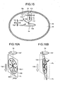
- a permanent magnet 19 is fixedly disposed to have a magnetization Ym2 in a direction perpendicular to the long axis La of the capsule endoscope 210.
- a gravity center location G of the capsule endoscope 210 is set to a location moved in a direction different from the magnetization Ym2 of the permanent magnet 19 from a geometric center C of the capsule endoscope 210, and a direction of the long axis of the capsule endoscope 210 may be controlled according to a change in a direction of a magnetic field in the liquid W. For example, as illustrated in FIG.
- the gravity center location G of the capsule endoscope 210 deviates from the long axis La of the capsule endoscope 210 from the geometric center C of the capsule endoscope 210 by adjusting disposition of the constituent elements of the capsule endoscope 210 such as a power source 18 and the permanent magnet 19.
- a magnetic field for guiding the capsule endoscope 210 as indicated by the arrows of FIG. 15 is generated from the magnetic field generating unit 2, by manipulating the joysticks 71 and 72 (see FIGS. 3A and 3B ), the up button 73U (see FIGS. 3A and 3B ), and the down button 73B (see FIGS. 3A and 3B ).
- the joystick 71 is tilted as indicated by the arrow Y1 illustrated in FIG. 3A
- the capsule endoscope 210 is guided to the left and right sides of the paper of FIG. 15 as indicated by the arrow Y21 of FIG. 15 .
- the capsule endoscope 210 is guided in a direction perpendicular to the paper of FIG. 15 .
- the capsule endoscope 210 is located on a point Y22 (see FIG. 15 )
- the capsule endoscope 210 is guided in a direction perpendicular to the paper of FIG. 15 to pass through the point Y22.
- the up button 73U is pressed as indicated by the arrow Y3u illustrated in FIG. 3(2)
- the capsule endoscope 210 is guided vertically upward as indicated by an arrow Y23u of FIG. 15 .
- the down button 73B is pressed as indicated by the arrow Y3b of FIG.
- the capsule endoscope 210 is guided vertically downward as indicated by an arrow Y23b of FIG. 15 . Further, when the joystick 72 is tilted as indicated by the arrow Y4 illustrated in FIG. 3(1) , an end of the capsule endoscope 210 is guided such that a neck is shaken to the upper and lower sides of the paper as indicated by an arrow Y24 of FIG. 15 . When the joystick 72 is tilted as indicated by the arrow Y5 illustrated in FIG. 3(1) , the capsule endoscope 210 is rotated about the vertical axis Az as indicated by an arrow Y25 of FIG. 15 .
- variable magnetic field button 91 illustrated in FIGS. 3A and 3B While the variable magnetic field button 91 illustrated in FIGS. 3A and 3B is pressed, the magnetic field controller 243 generates a variable magnetic field for moving the capsule endoscope 210 restricted on a liquid surface into a liquid in the magnetic field generating unit 2. As illustrated in FIGS. 16A and 16B , the variable magnetic field generated at this time is the same as that of the first embodiment.
- the variable magnetic field includes a rotating magnetic field where a direction of a magnetic field is rotated to the arrows Mr21, Mr22, and Mr23 at a predetermined period as indicated by an arrow Y26, and a magnetic field for generating a magnetic attracting force for moving the permanent magnet 19 to a lower side of the vertical axis Az as indicated by an arrow Y28.
- the rotating magnetic field has an intensity by which the capsule endoscope 210 can be moved, and the pivot period of the plane Pv about the vertical axis is set to be sufficiently longer than the rotation period in the plane Pv of the rotating magnetic field.
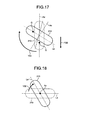
- FIG. 17 is a view illustrating the capsule endoscope 210 in the case where a rotation frequency of a rotating magnetic field is relatively low, when viewed from a direction perpendicular to the vertical axis.
- FIG. 18 is a view illustrating the capsule endoscope 210 in the case where a rotation frequency of a rotating magnetic field is relatively low, when viewed from a vertically upper side.
- the capsule endoscope 210 repeats an operation of rotating in a plane parallel to the vertical axis Az while pivoting about the vertical axis Az as the side where the gravity center G is located is tilted.
- FIG. 19 is a view when the capsule endoscope 210 is viewed from a direction perpendicular to the vertical axis in the case where a rotation frequency of the rotating magnetic field is a frequency higher than the rotation frequencies of the cases illustrated in FIGS. 17 and 18 and lower than a predetermined frequency (for example, 3 Hz).
- a vertically downward magnetic attracting force is always present as indicated by an arrow Y30 (see FIG.
- a frequency where the capsule endoscope 210 can be rotated about the center of the long axis of the capsule endoscope 210 in a plane parallel to the plane Pv is determined by the shape, the mass, and the like of the capsule endoscope 210 and the density and the like of the liquid.
- FIG. 20 is a view illustrating the capsule endoscope 210 in the case where a rotation frequency of a rotating magnetic field is equal to or higher than 3 Hz, when viewed from an upper side of the inclination.
- a rotation of the capsule endoscope 210 in the plane Pv is hampered by the liquid, and the capsule endoscope 210 is only rotated about the center of the vertical axis Az while being inclined as indicated by an arrow Y34 of FIG. 20 .
- the rotation frequency of the rotating magnetic field has only to be optimized in correspondence to the capsule endoscope 210 and the liquid into which the capsule endoscope 210 is introduced.
- the rotation frequency of the rotating magnetic field is set according to the type of the capsule endoscope 210 and the type of the liquid, and is selected according to the capsule endoscope 210 or the liquid which is actually used.
- the rotation frequency of the rotating magnetic field is selected by selection information of the rotation frequency input from the input unit 6. Further, the rotation frequency of the rotating magnetic field may be minutely adjusted through manipulation of the input unit 6.
- the capsule endoscope 210 can be always pulled vertically downward while rotating toward various directions, and thus the second embodiment shows the same effect as in the first embodiment.
- a density of the capsule endoscope 210 may be set to be substantially the same as a density of the liquid W introduced into the subject such that a magnetic attracting force for moving the capsule endoscope 210 vertically downward becomes small.
- variable magnetic field may be set to include a direction varying magnetic field where a direction of a magnetic field is periodically changed on the plane Pv.
- a direction of the plane Pv which is a rotation plane may be periodically changed about the vertical axis Az, and the plane Pv may not necessarily pivot about the vertical axis Az.
- a rotation plane of the rotating magnetic field may be a plane Ps (see FIG. 21 ) other the horizontal plane.
- the capsule endoscope 210 repeats a posture where at least the long axis La of the capsule endoscope 210 and the vertical axis Az are perpendicular to each other in a plane parallel to the plane Pv such that the capsule endoscope 10 is operated to be significantly shaken about the vertical axis Az.
- the magnetization Ym2 of the permanent magnet 19 is perpendicular to the long axis La of the capsule endoscope 210, and thus there is a need to generate a direction varying magnetic field having a timing facing at least the vertical direction such that the capsule endoscope 210 takes a posture where the long axis La is perpendicular to the vertical axis Az.
- a magnetic field for changing a direction of a magnetic field to a plurality of directions containing at least the vertical direction is set as a direction varying magnetic field. That is, it is sufficient only if a direction varying magnetic field is set to contain a magnetic field facing 90° or 270° with reference (0°) to the vertically upward direction.
- a direction of a magnetic field as the direction varying magnetic field may be set to be changed to the clockwise direction or the counterclockwise direction such that, as indicated by an arrow Y26a of FIG. 22 , the direction of the magnetic field forms an angle of 45° to 315° with respect to the vertical axis Az.
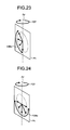
- a direction of a magnetic field may be set to be changed to the clockwise direction or the counterclockwise direction such that, as indicated by an arrow Y26b of FIG. 23 , the direction of the magnetic field forms an angle of 45° to 180° with respect to the vertical axis Az.
- a direction of a magnetic field may be set to be changed to the clockwise direction or the counterclockwise direction such that, as indicated by an arrow Y26c of FIG. 24 , the direction of the magnetic field forms an angle of 90° to 270° with respect to the vertical axis Az.
- a variable magnetic field including the direction varying magnetic field is generated, a magnetic attracting force by which an angle between the long axis La and the vertical axis Az of the capsule endoscope 210 is equal to or larger than 90° may be generated, and the capsule endoscope 210 may be released from the restriction of the surface tension while being significantly shaken about the vertical axis.
- the capsule endoscope 210 having a magnetization perpendicular to the long axis of the capsule endoscope has been described as an example, it is apparent that the present invention is not limited thereto and the permanent magnet 19 in the capsule endoscope may have a magnetization in a direction crossing the long axis of the capsule endoscope. Even the capsule endoscope can be rotated in correspondence to the rotation of a rotating magnetic field in a rotation plane of the rotating magnetic field included in the variable magnetic field by setting the center location of the capsule endoscope to a location moved in a direction different from the magnetization of the permanent magnet 19 from the geometric center of the capsule endoscope.
- the rotating magnetic field included in the variable magnetic field has been described while taking a case of rotation in a plane other than the horizontal plane as an example, it is apparent that the rotation may be made in a horizontal plane Ph as illustrated in FIG. 25 .
- the capsule endoscope 210 may deviate from the liquid while excluding a surface tension to rotate the horizontal plane Ph while the capsule endoscope 210 is always pulled as indicated by the arrow Y30 by a vertically downward magnetic attracting force.
Description
- The present invention relates to a capsule medical device guiding system for guiding a capsule medical device, which is introduced into a liquid in a subject and equipped with a permanent magnet, and a magnetic field generating device for generating a magnetic field for the capsule medical device.
- Conventionally, in the field of endoscopes, capsule endoscopes that include an imaging function and a wireless communication function in a capsule-shaped casing having a size introducible into an alimentary canal of a subject such as a patient have been developed. Such a capsule endoscope is swallowed through the mouth of a subject, and then is moved in the alimentary canal through peristaltic movement. The capsule endoscope sequentially acquires images (hereinafter, also referred to as in-vivo images) of internal organs of a subject, and wirelessly transmits the acquired in-vivo images to a receiving device outside the subject in sequence, during a time period until the capsule endoscope is excreted to the outside of the subject after being introduced into the alimentary canal of the subject.
- The in-vivo images captured by the capsule endoscope are input to an image display unit via the receiving device. The image display unit displays the input in-vivo images on a display in the form of still images or moving images. A user such as a doctor or a nurse observes various in-vivo images of the subject displayed on the image display unit, and examines the internal organs of the subject through observation of the in-vivo images.
- Further, in recent years, guiding systems for guiding (hereinafter, referred to as magnetically guiding) a capsule endoscope in a subject by using a magnetic force are being suggested. In general, in such a guiding system, the capsule endoscope further includes a permanent magnet within a capsule-shaped casing, and an image display unit displays various in-vivo images sequentially captured by the capsule endoscope within the subject in real time. The guiding system of the capsule endoscope applies a magnetic field for the capsule endoscope within the subject, and magnetically guides the capsule endoscope within the subject to a desired location due to a magnetic attracting force received by the applied magnetic field. The user manipulates magnetic guidance of the capsule endoscope by using a manipulation input unit of the system while referring to the in-vivo images displayed on the image display unit.
- For example, a magnetic guiding system for a capsule endoscope which applies a rotating magnetic field for rotating about a horizontal axis center of a long axis of the capsule endoscope and reciprocally rotates the capsule endoscope about the horizontal axis center of the long axis, in order to submerge the capsule endoscope located on a liquid surface into a liquid against a surface tension of the liquid surface has been suggested (see
Patent Literature 1, for example). Further, a technology of applying a magnetic field for pivoting a capsule endoscope in a long axis direction of the capsule endoscope while rotating the capsule endoscope about a long axis of the capsule endoscope has been suggested (seePatent Literature 2, for example). -
- Patent Literature 1: Japanese Laid-open Patent Publication No.
2010-017555 - Patent Literature 2: Japanese Laid-open Patent Publication No.
2005-058430 -
Document EP 2 143 371 A1 , on which document is based the preamble ofclaims - Document
US 2010/0307517 A1 relates to a medical device control system. In a jiggling mode, a magnetic field is generated around a capsule endoscope. The jiggling mode has a magnetic field change pattern that swingably rotates the capsule endoscope corresponding to a jiggling switch of an operation unit, wherein the magnetic field is generated by combining an oscillating magnetic field for oscillating the intensity of the magnetic field and a revolving magnetic field that revolves in one direction on a revolving magnetic field plane, which is in substantially the same direction as that of a rotating axis, about which the capsule endoscope rotates around. - When a capsule endoscope is controlled so as to be submerged into liquid from a liquid surface, the capsule endoscope is constrained by surface tension, and thus may not be submerged in the liquid. In this situation, the capsule endoscope is rotated to get rid of the constraint due to the surface tension. However, in the magnetic guiding system for the capsule endoscope disclosed in
Patent Literature 1 andPatent Literature 2, the capsule endoscope can be rotated only in one direction, which makes it difficult to release the capsule endoscope from the constraint due to the surface tension. Further, in the magnetic guiding system for the capsule endoscope disclosed inPatent Literature 1 andPatent Literature 2, if an obstacle such as a stomach wall exists in the rotation direction, the rotation of the capsule endoscope may be disturbed by the obstacle, and thus the capsule endoscope may not be moved. - The present invention has been made in view of the forgoing, and an object of the present invention is to provide a capsule medical device guiding system and a magnetic field generating device that allow the capsule medical device, which is constrained on a liquid surface, to be smoothly submerged into the liquid. Solution to Problem
- In order to solve the above problems and achieve the object, a capsule medical device guiding system and a magnetic field generating device according to the independent claims is provided.
- A capsule medical device includes a permanent magnet and is configured to be introduced into a liquid in a subject; a magnetic field generating unit configured to generate a magnetic field to be applied to the permanent magnet to guide the capsule medical device, and configured to change a direction of the generated magnetic field in a three-dimensional space; and a control unit configured to cause the magnetic field generating unit to generate a variable magnetic field including a direction varying magnetic field whose magnetic field direction varies periodically on a plane whose direction changes periodically about a vertical axis and which is other than a horizontal plane, and a magnetic field for generating a magnetic attracting force for moving the capsule endoscope vertically downward.
- In the capsule medical device guiding system of an embodiment of the invention, the direction varying magnetic field periodically changes each of an angle, which is between a long axis of the capsule medical device and the vertical axis, and an angle, which is between a predetermined reference plane passing through the vertical axis and a plane passing through the long axis of the capsule medical device and the vertical axis.
- In the capsule medical device guiding system of an embodiment of the invention, the direction varying magnetic field generates a magnetic attracting force which makes an angle between a long axis of the capsule medical device and the vertical axis equal to or larger than 90°.
- In the capsule medical device guiding system of an embodiment of the invention, the direction varying magnetic field is a rotating magnetic field whose magnetic field direction is periodically rotated on the plane, and the plane pivots about the vertical axis.
- In the capsule medical device guiding system of an embodiment of the invention, the capsule medical device is configured to move in a liquid introduced into the subject, and has substantially a same density as a density of the liquid introduced into the subject.
- In the capsule medical device guiding system of an embodiment of the invention, the permanent magnet has a magnetization in a direction parallel to a long axis of the capsule medical device.
- In the capsule medical device guiding system of an embodiment of the invention, there is at least timing at which the direction varying magnetic field faces a horizontal direction.
- In the capsule medical device guiding system of an embodiment of the invention, the permanent magnet has a magnetization in a direction crossing a long axis of the capsule medical device, and a gravity center location of the capsule medical device is a location which is deviated from a geometric center of the capsule medical device in a direction different from the magnetization of the permanent magnet.
- In the capsule medical device guiding system of an embodiment of the invention, the permanent magnet has a magnetization in a direction perpendicular to the long axis of the capsule medical device, and there is at least timing at which the direction varying magnetic field faces a vertical direction.
- In the capsule medical device guiding system of an embodiment of the invention, a change period of the direction of the plane about the vertical axis is longer than a change period of a direction of the direction varying magnetic field on the plane.
- A magnetic field generating device according to an embodiment of the invention is a magnetic field generating device for generating a magnetic field for a capsule medical device including a permanent magnet. The magnetic field generating device includes: a magnetic field generating unit configured to generate a magnetic field to be applied to the permanent magnet to guide the capsule medical device, and configured to change a direction of the generated magnetic field in a three-dimensional space; and a control unit configured to cause the magnetic field generating unit to generate a variable magnetic field including a direction varying magnetic field whose magnetic field direction varies periodically on a plane whose direction changes periodically about a vertical axis and which is other than a horizontal plane, and a magnetic field for generating a magnetic attracting force for moving the capsule endoscope vertically downward.
- According to an embodiment of the invention, a variable magnetic field is generated to be applied to a permanent magnet of a capsule medical device. The variable magnetic field includes a direction varying magnetic field whose magnetic field direction varies periodically on an arbitrary plane whose direction changes periodically about a vertical axis and which is other than a horizontal plane, and a magnetic field for generating a magnetic attracting force for moving the capsule medical device vertically downward. Therefore, the capsule medical device can be always pulled vertically downward while rotating toward various directions, and thus the capsule medical device can be released from constraint due to surface tension of a liquid surface and be smoothly submerged into the liquid.
-
-
FIG. 1 is a schematic diagram illustrating an entire configuration of a capsule medical device guiding system according to a first embodiment; -
FIG. 2 is a sectional schematic diagram illustrating an exemplary configuration of a capsule endoscope illustrated inFIG. 1 ; -
FIGS. 3A and 3B illustrate views of an example of a manipulation input unit used in the capsule medical device guiding system according to the first embodiment; -
FIG. 4 is a view illustrating magnetization of a permanent magnet of the capsule endoscope illustrated inFIG. 1 and an operation of the capsule endoscope; -
FIGS. 5A and 5B illustrate views of a variable magnetic field generated by a magnetic field generating unit illustrated inFIG. 1 ; -
FIG. 6 is a view illustrating an operation of the capsule endoscope illustrated inFIG. 1 when a variable magnetic field is generated; -
FIG. 7 is a view exemplifying a menu screen displayed on a display unit illustrated inFIG. 1 ; -
FIG. 8 is a view exemplifying a menu screen displayed on the display unit illustrated inFIG. 1 ; -
FIG. 9 illustrates a view of another example of a variable magnetic field generated by the magnetic field generating unit illustrated inFIG. 1 ; -
FIG. 10 illustrates a view of another example of a variable magnetic field generated by the magnetic field generating unit illustrated inFIG. 1 ; -
FIG. 11 illustrates a view of another example of a variable magnetic field generated by the magnetic field generating unit illustrated inFIG. 1 ; -
FIG. 12 illustrates a view of another example of a variable magnetic field generated by the magnetic field generating unit illustrated inFIG. 1 ; -
FIG. 13 is a view exemplifying a menu screen displayed on the display unit illustrated inFIG. 1 ; -
FIG. 14 is a schematic diagram illustrating an entire configuration of a capsule medical device guiding system according to a second embodiment; -
FIG. 15 is a view illustrating magnetization of a permanent magnet of a capsule endoscope illustrated inFIG. 14 and an operation of the capsule endoscope; -
FIGS. 16A and 16B illustrate views of a variable magnetic field generated by a magnetic field generating unit illustrated inFIG. 14 ; -
FIG. 17 is a view illustrating an operation of the capsule endoscope illustrated inFIG. 14 in the case where a rotation frequency of a rotating magnetic field is relatively low, when the capsule endoscope is viewed from a lateral side; -
FIG. 18 is a view illustrating the capsule endoscope illustrated inFIG. 14 in the case where a rotation frequency of a rotating magnetic field is relatively low, when the capsule endoscope is viewed from an upper side; -
FIG. 19 is a view illustrating the capsule endoscope illustrated inFIG. 1 in the case where a rotation frequency of a rotating magnetic field is lower than 3 Hz, when the capsule endoscope is viewed from a lateral side; -
FIG. 20 is a view illustrating an operation of the capsule endoscope in the case where a rotation frequency of a rotating magnetic field is equal to or higher than 3 Hz, when the capsule endoscope is viewed from a lateral side; -
FIG. 21 illustrates a view of another example of a variable magnetic field generated by the magnetic field generating unit illustrated inFIG. 14 ; -
FIG. 22 illustrates a view of another example of a variable magnetic field generated by the magnetic field generating unit illustrated inFIG. 14 ; -
FIG. 23 illustrates a view of another example of a variable magnetic field generated by the magnetic field generating unit illustrated inFIG. 14 ; -
FIG. 24 illustrates a view of another example of a variable magnetic field generated by the magnetic field generating unit illustrated inFIG. 14 ; and -
FIG. 25 illustrates a view of another example of a variable magnetic field generated by the magnetic field generating unit illustrated inFIG. 14 . - Hereinafter, in regard to a capsule medical device guiding system according to an embodiment of the present invention, a guiding system for a capsule endoscope which uses a capsule endoscope introduced into an oral of a subject and floating in a liquid accumulated on a stomach of the subject will be described as an example. Meanwhile, the present invention is not limited thereto, but may use various capsule medical devices such as, for example, a capsule endoscope moving in a lumen from the gullet of a subject along the anal or a capsule endoscope introduced from the anal together with an isotonic solution. Further, in the description of the drawings, the same reference numerals denote the same parts.
- First, a first embodiment will be described.
FIG. 1 is a schematic diagram illustrating an entire configuration of a capsule medical device guiding system according to a first embodiment of the present invention. - As illustrated in
FIG. 1 , a capsule medical device guiding system 1 according to the first embodiment includes a capsule endoscope 10 which is a capsule medical device swallowed through the mouth of a subject to be introduced into a body cavity in the subject and configured to communicate with an external device, a magnetic field generating unit 2 provided around the subject and configured to generate a three-dimensional magnetic field, a transmitting/receiving unit 3 configured to perform a wireless communication with the capsule endoscope 10 and configured to receive a wireless signal containing an image captured by the capsule endoscope 10 and transmit a manipulation signal for the capsule endoscope 10, a control unit 4 configured to control various constituent elements of the capsule medical device guiding system 1, a display unit 5 configured to display and output the image captured by the capsule endoscope 10, an input unit 6 configured to input instruction information for instructing various manipulations in the capsule medical device guiding system 1, a manipulation input unit 7 configured to input guidance instructing information for magnetically guiding the capsule endoscope 10, a storage unit 8 configured to store image information captured by the capsule endoscope 10, and a variable magnetic field generation instructing unit 9 configured to input variable magnetic field instructing information for instructing generation of a variable magnetic field for moving the capsule endoscope 10 restricted to a liquid surface into the liquid. - The
capsule endoscope 10 is a capsule medical device configured to acquire an in-vivo image of a subject, and employs an imaging function and a wireless communication function therein. After being introduced into an internal organ of a subject together with a specific liquid through an oral ingestion, thecapsule endoscope 10 is moved through the interior of an alimentary canal and is finally excreted to the outside of the subject. Thecapsule endoscope 10 sequentially captures in-vivo images in the subject, and sequentially wirelessly transmits the obtained in-vivo images to the external transmitting/receivingunit 3. Further, thecapsule endoscope 10 employs a magnetic body such as a permanent magnet therein. Thecapsule endoscope 10 drifts in the liquid introduced into an interior of an alimentary canal (for example, an interior of a stomach) of the subject, and is moved in the liquid while being magnetically guided by the external magneticfield generating unit 2. -
FIG. 2 is a sectional schematic diagram illustrating an exemplary configuration of the capsule endoscope illustrated inFIG. 1 . As illustrated inFIG. 2 , thecapsule endoscope 10 includes a first imaging unit 11A, asecond imaging unit 11B, a capsule-shapedcasing 12, aprocessing unit 15, a transmittingunit 16, apower source 18, and apermanent magnet 19. The first imaging unit 11A and thesecond imaging unit 11B have an illumination system such as an LED, an optical system such as a condenser lens, and an imaging element such as a CMOS image sensor or a CCD, respectively, and capture images of a subject in different imaging directions. The capsule-shapedcasing 12 is an external body formed to have a size easily introducible into the interior of an alimentary canal of a subject, and is configured such that opposite opening ends of a substantially opaque coloredtubular casing 12a are blocked by dome-shapedtransparent casings capsule endoscope 10 is a two-lens capsule medical device for capturing a front side and a rear side in a direction of a long axis La, the optical axes of the first imaging unit 11A and thesecond imaging unit 11B are substantially parallel to or substantially the same as the long axis La which is a lengthwise center axis of the capsule-shapedcasing 12. Theprocessing unit 15 performs various processing such as noise removing processing or amplifying processing for various images captured by the first imaging unit 11A and thesecond imaging unit 11B. The transmittingunit 16 generates a wireless signal obtained by modulating an image signal containing various images processed by theprocessing unit 15, and transmits the wireless signal to the external transmitting/receivingunit 3 via an antenna (not illustrated). Thepower source 18 has an accumulating unit such as a button type battery or a capacitor and a switch unit such as a magnetic switch, and supplies electric power to the constituent elements of thecapsule endoscope 10. Thepermanent magnet 19 is for enabling a magnetic guidance by the magneticfield generating unit 2, and is fixedly disposed within the capsule-shapedcasing 12. - The magnetic
field generating unit 2 is for magnetically guiding thecapsule endoscope 10 in the subject. The magneticfield generating unit 2 is realized by using, for example, a plurality of coils, and generates a guiding magnetic field by using electric power supplied by an electric power supply unit (not shown). The magneticfield generating unit 2 applies the generated guiding magnetic field to a magnetic body in thecapsule endoscope 10, and magnetically captures thecapsule endoscope 10 through an operation of the guiding magnetic field. The magneticfield generating unit 2 may change a direction of the generated magnetic field in a three-dimensional space. The magneticfield generating unit 2 changes a magnetic field direction of the guiding magnetic field applied to thecapsule endoscope 10 in the subject to control a three-dimensional posture of thecapsule endoscope 10 in the subject. - The transmitting/receiving
unit 3 includes a plurality ofantennas 3a, and receives in-vivo images of the subject from thecapsule endoscope 10 via the plurality ofantennas 3a. The transmitting/receivingunit 3 sequentially receives wireless signals from thecapsule endoscope 10 via the plurality ofantennas 3a. The transmitting/receivingunit 3 selects an antenna having the highest received magnetic field intensity among the plurality ofantennas 3a, and performs demodulating processing on the wireless signals from thecapsule endoscope 10 received via the selected antenna. Accordingly, the transmitting/receivingunit 3 extracts image data by thecapsule endoscope 10, that is, in-vivo image data of the subject from the wireless signal. The transmitting/receivingunit 3 transmits image signals containing the extracted in-vivo image data to thecontrol unit 4. - The
control unit 4 controls operations of the magneticfield generating unit 2, the transmitting/receivingunit 3, thedisplay unit 5, and the storage unit 8, and controls input/output of signals between the constituent elements. Thecontrol unit 4 controls the storage unit 8 to store the in-vivo image group of the subject acquired from the transmitting/receivingunit 3. Thecontrol unit 4 includes animage receiving unit 41 configured to sequentially acquire the in-vivo images sequentially received by the transmitting/receivingunit 3, animage display controller 42 configured to display the in-vivo images sequentially received by the transmitting/receivingunit 3 on thedisplay unit 5 in real time, and amagnetic field controller 43 configured to control the magneticfield generating unit 2 to guide thecapsule endoscope 10. Themagnetic field controller 43 controls an amount of current flowed to the magneticfield generating unit 2, and controls the magneticfield generating unit 2 to generate a guiding magnetic field necessary for magnetic guidance of thecapsule endoscope 10 according to a magnetic guidance direction and a magnetic guidance location based on guidance instructing information. - The
display unit 5 is realized by using various displays such as a liquid crystal monitor, and displays various information instructed to display by thecontrol unit 4. In detail, thedisplay unit 5 displays, for example, an in-vivo image group of the subject captured by thecapsule endoscope 10, based on the control of theimage display controller 42 in thecontrol unit 4. Further, thedisplay unit 5 displays reduced images of the in-vivo images selected or marked through an input manipulation of the input unit 6 among the in-vivo image group, and patient information and examination information of the subject. - The input unit 6 is realized by using an input device such as a keyboard and a mouse, and inputs various information to the
control unit 4 according to an input manipulation by a user such as a doctor. The various information input to thecontrol unit 4 by the input unit 6 may include, for example, instruction information instructed to thecontrol unit 4, and patient information and examination information of the subject. Further, the patient information of the subject is specific information specifying the subject, and includes, for example, a patent name, a patent ID, a birth date, a gender, and an age of the subject. Further, the examination information of the subject is specific information specifying an examination for introducing thecapsule endoscope 10 into the interior of the alimentary canal of the subject and observing the interior of the alimentary canal, and includes, for example, an examination ID and an examination date. - Guidance instructing information for magnetically guiding the
capsule endoscope 10 is input to themanipulation input unit 7. Themanipulation input unit 7 inputs guidance instructing information for magnetically guiding thecapsule endoscope 10, which is a magnetic guidance manipulated object, to thecontrol unit 4. The guidance instructing information is for instructing a posture or a location of thecapsule endoscope 10. Themagnetic field controller 43 generates a magnetic field corresponding to the guidance instructing information in the magneticfield generating unit 2. Themanipulation input unit 7 has configurations including a joystick, various buttons, and various switches, and inputs the guidance instructing information to thecontrol unit 4 as the joystick is manipulated by a user. - For example, as illustrated in
FIG. 3A , themanipulation input unit 7 is configured as a manipulation input unit including twojoysticks joysticks capsule endoscope 10 through magnetic guidance, and may be tilted to the upper side, lower side, left side, and right side of the paper. Further, as illustrated inFIG. 3B , an upbutton 73U and adown button 73B are provided on a rear surface of thejoystick 71. - As a capsule endoscope magnetically guided in response to tilting manipulations of the
joysticks capsule endoscope 10, in which thepermanent magnet 19 is fixedly disposed to have a magnetization Ym in a direction parallel to the long axis La of thecapsule endoscope 10 as illustrated inFIG. 4 , will be described as an example. Incidentally,FIG. 4 is a view where thecapsule endoscope 10 is viewed from a direction perpendicular to a vertical axis, and exemplifies that thecapsule endoscope 10 is located within the stomach St. Further, the density of thecapsule endoscope 10 is set to be substantially the same as the density of a liquid W introduced into the subject.FIG. 4 exemplifies that thecapsule endoscope 10 is located on the liquid surface Ws of the liquid W. - As indicated by an arrow Y1 illustrated in
FIG. 3A , when thejoystick 71 is tilted between the rear side of the paper and the front surface of the paper ofFIG. 3A , guidance instructing information for guiding thecapsule endoscope 10 to the left and right sides ofFIG. 4 is input to thecontrol unit 4 as indicated by the arrow Y1 (seeFIG. 4 ). As indicated by an arrow Y2 illustrated inFIG. 3A , when thejoystick 71 is tilted to the left and right sides of the paper, guidance instructing information for guiding thecapsule endoscope 10 in a direction perpendicular to the paper ofFIG. 4 is input to thecontrol unit 4. For example, when thecapsule endoscope 10 is located on a point Y12 (seeFIG. 4 ), thecapsule endoscope 10 is guided in a direction perpendicular to the paper ofFIG. 4 to pass through the point Y12. - As indicated by an arrow Y3u illustrated in
FIG. 3B , when the upbutton 73U is pressed, guidance instructing information for instructing guidance of thecapsule endoscope 10 vertically upward is input to thecontrol unit 4 as indicated by an arrow Y13u ofFIG. 4 . As indicated by an arrow Y3b illustrated inFIG. 3B , when thedown button 73B is pressed, guidance instructing information for instructing guidance of thecapsule endoscope 10 vertically downward is input to thecontrol unit 4 as indicated by an arrow Y13b ofFIG. 4 . - As indicated by an arrow Y4 illustrated in
FIG. 3A , when thejoystick 72 is tilted between the rear side of the paper and the front surface of the paper ofFIG. 3A , guidance instructing information for operating thecapsule endoscope 10 such that an end of thecapsule endoscope 10 is shaken to the upper and lower sides of the paper as a neck is shaken is input to thecontrol unit 4 as indicated by the arrow Y14 (seeFIG. 4 ). As indicated by an arrow Y5 illustrated inFIG. 3(1) , when thejoystick 72 is tilted to the left and right sides of the paper, guidance instructing information for guiding thecapsule endoscope 10 to rotate about a vertical axis Az as illustrated in an arrow Y15 ofFIG. 4 is input to thecontrol unit 4. - The storage unit 8 is realized by using a storage medium, such as flash memory or a hard disk, for rewritably preserving information. The storage unit 8 stores various information instructed to store by the
control unit 4, and delivers information instructed to be read out by thecontrol unit 4 in the stored information to thecontrol unit 4. Further, the various information stored by the storage unit 8 may include, for example, various image data of the in-vivo image group of the subject captured by thecapsule endoscope 10, data of the in-vivo images selected through the input manipulation of the input unit 6 among the in-vivo images displayed on thedisplay unit 5, and input information by the input unit 6 such as patient information of the subject. - The variable magnetic field
generation instructing unit 9 includes a variablemagnetic field button 91 in the manipulation input unit illustrated inFIGS. 3A and 3B , and when the variablemagnetic field button 91 is pressed as indicated by an arrow Y6 (seeFIG. 3B ), variable magnetic field instructing information for instructing generation of a variable magnetic field is input to thecontrol unit 4. While the variable magnetic field instructing information is input, themagnetic field controller 43 generates a variable magnetic field for moving thecapsule endoscope 10 restricted on a liquid surface into a liquid in the magneticfield generating unit 2. - The variable magnetic field will be described with reference to
FIGS. 5A and 5B. FIGS. 5A and 5B illustrate views of a variable magnetic field generated by the magneticfield generating unit 2. As illustrated inFIGS. 5A and 5B , the variable magnetic field includes a rotating magnetic field where a direction of the magnetic field is rotated as indicated by the arrow Y16 on a plane Pv parallel to a vertical axis Az, and a magnetic field for generating a magnetic attracting force for moving thepermanent magnet 19 in a downward direction of the vertical axis Az as indicated by an arrow Y18. The magnetic field rotating on the plane Pv is pivoted about the vertical axis Az while rotating.FIGS. 5A and 5B illustrate only a representative vector of the direction vector of the rotating magnetic field generated by the magnetic field generating unit. The rotating magnetic field is a magnetic field having an intensity, by which thecapsule endoscope 10 can be moved, and a direction rotating about an arbitrary point of the plane Pv at a predetermined period as indicated by arrows Mr11, Mr12, and Mr13. Further, the magnetic field for generating the magnetic attracting force in the vertically downward direction is set, for example, such that an intensity thereof becomes stronger toward a lower side from an upper side of the vertical axis Az. - Further, as indicated by an arrow Y17 of
FIG. 5A , the magneticfield generating unit 2 generates a magnetic field such that the plane Pv is pivoted about the vertical axis Az at a predetermined period. For example, the plane Pv is pivoted about the vertical axis Az as indicated by an arrow Y17a ofFIG. 5B until a predetermined time elapses from the state illustrated inFIG. 5A . Further, the pivot period of the plane Pv about the vertical axis Az is set to be sufficiently longer than a rotation period on the plane Pv of the rotating magnetic field so that the pivot of the plane Pv about the vertical axis Az does not influence the rotation of the rotating magnetic field. -
FIG. 6 is a view illustrating an operation of the capsule endoscope when a variable magnetic field is generated.FIG. 6 is a view where thecapsule endoscope 10 is viewed from a direction perpendicular to the vertical axis Az. As the variable magnetic field is generated, on a plane parallel to the plane Pv, as indicated by an arrow Y19 illustrated inFIG. 6 , a magnetic attracting force for rotating thecapsule endoscope 10 about a center of the long axis of thecapsule endoscope 10 and a magnetic attracting force for moving thecapsule endoscope 10 vertically downward as indicated by an arrow Y20 are generated at the same time. For this reason, thecapsule endoscope 10 is pulled vertically downward while rotating on a plane parallel to the plane Pv. - Further, as the plane Pv is pivoted about the vertical axis Az at a predetermined period, the rotation plane in which the
capsule endoscope 10 is rotated is also pivoted about the vertical axis Az. Thus, as thecapsule endoscope 10 is also pivoted about the vertical axis Az in response to the pivot of the rotation plane while rotating in a plane parallel to the plane Pv, a rotation direction of thecapsule endoscope 10 is varied in response to the pivot of the rotation plane. - In this way, in the first embodiment, as the variable magnetic field is generated, the
capsule endoscope 10 may be rotated in various directions, and thus thecapsule endoscope 10 is apt to deviate from the restriction of a surface tension as compared with the case where a rotating operation is performed only in one direction. - Further, in the first embodiment, even when an obstacle such as a stomach wall exists, as a variable magnetic field is generated, the rotation plane in which the
capsule endoscope 10 is rotated is periodically pivoted by itself, and thus when the rotation plane is rotated in a direction deviating from the obstacle, thecapsule endoscope 10 may be moved in a direction where thecapsule endoscope 10 is not hindered by the obstacle. For this reason, in the first embodiment, even when an obstacle exists, thecapsule endoscope 10 may be moved in a direction deviating from the obstacle, and a problem in that thecapsule endoscope 10 may be hampered by an obstacle so as not to perform a rotating operation and thecapsule endoscope 10 may not be moved can be solved. - In addition, in the first embodiment, as the variable magnetic field is generated, the
capsule endoscope 10 may be always pulled vertically downward while rotating toward various directions, and thus thecapsule endoscope 10 can be released from the restriction of a surface tension of a liquid surface and be smoothly submerged into the liquid. - Furthermore, in the first embodiment, the movement of the
capsule endoscope 10 is realized by combination of rotating magnetic fields of a power source having a low load, by which a magnetic field is smoothly varied, and thus a power source in the capsule medicaldevice guiding system 1 can be miniaturized. - Further, in the
capsule endoscope 10 in the first embodiment, the magnetization Ym of thepermanent magnet 19 is parallel to the long axis La of thecapsule endoscope 10, and thecapsule endoscope 10 is rotated such that the direction of the long axis La coincides with the direction of the rotating magnetic field while the variable magnetic field is generated, and thus thecapsule endoscope 10 is efficiently rotated with respect to the rotating magnetic field. For this reason, in the first embodiment, a marginal value of a magnetic field intensity of the rotating magnetic field may become small. - In addition, in the capsule medical
device guiding system 1 according to the first embodiment, while the magneticfield generating unit 2 generates a variable magnetic field according to variable magnetic field instructing information, a purpose of selecting a variable magnetic field is displayed on thedisplay unit 5, and thus a manipulator is notified of generation of a variable magnetic field. - For example, as illustrated in
FIG. 7 , thedisplay unit 5 displays a menu Sa displaying a variable magnetic field icon Ic for notifying generation of a variable magnetic field on a left lower side, on the display screen. The variable magnetic field icon Ic is displayed by a bright color while the magneticfield generating unit 2 generates a variable magnetic field, and is displayed by a dark color while the magneticfield generating unit 2 stops generating a variable magnetic field. - Various subject information such as a patient name, a patient ID, a birth date, a gender, and an age of a subject is displayed in an area S1 on the left upper side of the menu Sa. In a central area S2 of the menu Sa, a living body image Sg1 captured by the imaging unit 11A is displayed on the left side and a living body image Sg2 captured by the
imaging unit 11B is displayed on the right side. In an area S3 below the area S2 of the menu Sa, the captured images are reduced and displayed together with a capture time. In an area S4 on the left side of the menu Sa, a posture diagram Sg3 in a horizontal plane and a posture diagram Sg4 in a vertical plane are displayed as posture diagrams of thecapsule endoscope 10. The postures of thecapsule endoscope 10 displayed on the posture diagrams Sg3 and Sg4 display postures corresponding to guidance instructing information of themanipulation input unit 7. In the posture diagrams Sg3 and Sg4, a direction in which thecapsule endoscope 10 can be guided is indicated by an arrow. - Further, in the first embodiment, the generation states of the variable magnetic field during guidance of the
capsule endoscope 10 may be preserved to correspond to the images, respectively. In this case, when an image is play backed after observation, it may be recognized whether thecapsule endoscope 10 is guided with a variable magnetic field when the playback image is acquired, by displaying the variable magnetic field icon Icb representing generation of a variable magnetic field corresponding to the playback image on the left lower side of the menu Sb together with the playback image in the playback menu Sb (seeFIG. 8 ). In addition, in an area S5 of the display menu Sb, an icon Ip for instructing playback of an image or an icon Is for temporary stop is displayed. - Further, in the first embodiment, although a rotating magnetic field for continuously rotating a direction of a magnetic field in the plane Pv parallel to the vertical axis Az has been described to be included as a variable magnetic field, as long as a rotating magnetic field capable of rotating the
capsule endoscope 10 about a center of a long axis of thecapsule endoscope 10 is included, a variable magnetic field including a direction varying magnetic field which periodically varies a direction of a magnetic field on a plane Pv may be used. - For example, as the direction varying magnetic field, in a plane Pv (see
FIGS. 5A and 5B ) parallel to the vertical axis Az, it is considered that a direction of a magnetic field having an intensity by which thecapsule endoscope 10 is movable is changed to a direction of an arrow Mr11 (seeFIGS. 5A and 5B ) at a time t1, is changed to a direction of an arrow Mr12 (seeFIGS. 5A and 5B ) at a time t2 after lapse of a predetermined time from the time t1, and is changed to a direction of an arrow Mr13 (seeFIGS. 5A and 5B ) at a time t3 after lapse of a predetermined time from the time t2. When the magneticfield generating unit 2 generates the direction varying magnetic field, as an angle of the magnetic field direction on a plane is changed by a predetermined angle at an interval of a predetermined time, thecapsule endoscope 10 may also be periodically rotated in a plane parallel to the plane Pv about a center of the long axis of thecapsule endoscope 10 according to a direction of the changed magnetic field. Thus, in the first embodiment, by generating a variable magnetic field including a direction varying magnetic field for periodically changing a direction of a magnetic field in the plane Pv pivoting about the vertical axis Az, an angle between the long axis La of thecapsule endoscope 10 and the vertical axis Az can be periodically changed and an angle between a reference plane (for example, a plane located in the plane Pv illustrated inFIG. 5A ) passing through the vertical axis Az and a plane through which the long axis La of thecapsule endoscope 10 and the vertical axis Az pass can also be periodically changed. - Further, in the first embodiment, although a case of pivoting the plane Pv which is a rotation plane of a rotating magnetic field about the vertical axis Az at a predetermined period has been described as an example, it is sufficient only if a rotating direction of the
capsule endoscope 10 may be changed, and thus a direction of the plane Pv may be only periodically changed about the vertical axis even without continuously pivoting the plane Pv. - Further, in the first embodiment, it is sufficient only if the
capsule endoscope 10 is operated such that one end of thecapsule endoscope 10 faces a direction close to a vertically lower side to submerge thecapsule endoscope 10 in the liquid, and thus a rotation plane of the rotating magnetic field may be a plane other the horizontal plane. Thus, for example, the plane Ps which is a plane crossing the vertical axis Az illustrated inFIG. 9 may be set to the rotation plane of the rotating magnetic field. As indicted by an arrow Y17, the plane Ps is also controlled by themagnetic field controller 43 such that a direction thereof is periodically changed about the vertical axis Az. - Further, in the first embodiment, although a rotating magnetic field where a direction of a magnetic field is rotated has been described as a direction varying magnetic field, the present invention is not limited thereto. It is sufficient only if the
capsule endoscope 10 repeats a posture where at least the long axis La of thecapsule endoscope 10 and the vertical axis Az are perpendicular to each other in a plane parallel to the plane Pv such that thecapsule endoscope 10 is operated to be significantly swung about the vertical axis Az. As illustrated inFIG. 4 , the magnetization Ym of thepermanent magnet 19 is parallel to the long axis La of thecapsule endoscope 10, and thus there is a need to generate a direction varying magnetic field having a timing facing at least the horizontal direction such that thecapsule endoscope 10 takes a posture where the long axis La is perpendicular to the vertical axis Az. Thus, in the first embodiment, it is sufficient only if a magnetic field for changing a direction of a magnetic field to a plurality of directions containing at least the horizontal direction is set as a direction varying magnetic field. That is, it is sufficient only if a direction varying magnetic field is set to contain a magnetic field facing 0° or 180° with reference to the vertically upward direction. - A case of taking the counterclockwise direction as a positive direction with reference (0°) to the vertically upward direction will be described. For example, a direction of a magnetic field as the direction varying magnetic field may be set to be changed to the clockwise direction or the counterclockwise direction such that, as indicated by an arrow Y16a of
FIG. 10 , the direction of the magnetic field forms an angle of -45° to 225° with respect to the vertical axis Az. For example, a direction of a magnetic field may be set to be changed to the clockwise direction or the counterclockwise direction such that, as indicated by an arrow Y16b ofFIG. 11 , the direction of the magnetic field forms an angle of 90° to 225° with respect to the vertical axis Az. For example, a direction of a magnetic field may be set to be changed to the clockwise direction or the counterclockwise direction such that, as indicated by an arrow Y16c ofFIG. 12 , the direction of the magnetic field forms an angle of 0° to 180° with respect to the vertical axis Az. As a variable magnetic field including the direction varying magnetic field is generated, a magnetic attracting force by which an angle between the long axis La and the vertical axis Az of thecapsule endoscope 10 is equal to or larger than 90° may be generated, and thecapsule endoscope 10 may be released from the restriction of the surface tension while being significantly shaken about the vertical axis Az. - Further, in the first embodiment, a desired variable magnetic field may be selected from a plurality of variable magnetic fields including the above-described direction varying magnetic fields. For example, when two variable magnetic fields are set, the manipulator may select a desired variable magnetic field from the two variable magnetic fields through manipulation of the input unit 6. In addition, the type of the selected variable magnetic field is displayed in a variable magnetic field icon Ic1 of the menu Sc illustrated in
FIG. 13 . Furthermore, the variable magnetic field icon Ic1 ofFIG. 13 exemplifies a case of selecting a variablemagnetic field 1 when the variablemagnetic field 1 and a variablemagnetic field 2 are set. When the variablemagnetic field 2 is selected, the display of the variable magnetic field icon Ic1 is changed to a display where the variablemagnetic field 2 is displayed. - Further, in the first embodiment, a magnetic attracting force for moving the
capsule endoscope 10 vertically downward may become small as compared with the case where a density of thecapsule endoscope 10 is smaller than a density of the liquid W introduced into the subject, by setting the density of thecapsule endoscope 10 to be substantially the same as the density of the liquid W. In this case, an amount of energy supplied to generate a magnetic field in the magneticfield generating unit 2 becomes small and a load of the power source of the capsule medicaldevice guiding system 1 becomes lower, and thus the power source can be miniaturized. - Next, a second embodiment will be described. In the second embodiment, a case of using a capsule endoscope having a magnetization in a direction crossing a long axis of the capsule endoscope will be described.
-
FIG. 14 is a schematic diagram illustrating an entire configuration of a capsule medical device guiding system according to the second embodiment. As illustrated inFIG. 14 , a capsule medicaldevice guiding system 201 according to the second embodiment employs acapsule endoscope 210 instead of thecapsule endoscope 10 illustrated inFIG. 1 . The capsule medicaldevice guiding system 201 according to the second embodiment has acontrol unit 204 instead of thecontrol unit 4 illustrated inFIG. 1 . Thecontrol unit 204 has amagnetic field controller 243 for controlling the magneticfield generating unit 2 to generate a magnetic field for guidance including a variable magnetic field corresponding to thecapsule endoscope 210. Further, the capsule medicaldevice guiding system 201 has the same manipulation input unit as the manipulation input unit illustrated inFIGS. 3A and 3B , and inputs guidance instructing information and the like to thecontrol unit 204 from the manipulation input unit. - As illustrated in
FIG. 15 , in thecapsule endoscope 210, apermanent magnet 19 is fixedly disposed to have a magnetization Ym2 in a direction perpendicular to the long axis La of thecapsule endoscope 210. Further, a gravity center location G of thecapsule endoscope 210 is set to a location moved in a direction different from the magnetization Ym2 of thepermanent magnet 19 from a geometric center C of thecapsule endoscope 210, and a direction of the long axis of thecapsule endoscope 210 may be controlled according to a change in a direction of a magnetic field in the liquid W. For example, as illustrated inFIG. 15 , the gravity center location G of thecapsule endoscope 210 deviates from the long axis La of thecapsule endoscope 210 from the geometric center C of thecapsule endoscope 210 by adjusting disposition of the constituent elements of thecapsule endoscope 210 such as apower source 18 and thepermanent magnet 19. - As a result, a magnetic field for guiding the
capsule endoscope 210 as indicated by the arrows ofFIG. 15 is generated from the magneticfield generating unit 2, by manipulating thejoysticks 71 and 72 (seeFIGS. 3A and 3B ), the upbutton 73U (seeFIGS. 3A and 3B ), and thedown button 73B (seeFIGS. 3A and 3B ). Further, as in the first embodiment, when thejoystick 71 is tilted as indicated by the arrow Y1 illustrated inFIG. 3A , thecapsule endoscope 210 is guided to the left and right sides of the paper ofFIG. 15 as indicated by the arrow Y21 ofFIG. 15 . When thejoystick 71 is tilted as indicated by the arrow Y2 illustrated inFIG. 3A , thecapsule endoscope 210 is guided in a direction perpendicular to the paper ofFIG. 15 . For example, when thecapsule endoscope 210 is located on a point Y22 (seeFIG. 15 ), thecapsule endoscope 210 is guided in a direction perpendicular to the paper ofFIG. 15 to pass through the point Y22. When the upbutton 73U is pressed as indicated by the arrow Y3u illustrated inFIG. 3(2) , thecapsule endoscope 210 is guided vertically upward as indicated by an arrow Y23u ofFIG. 15 . When thedown button 73B is pressed as indicated by the arrow Y3b ofFIG. 3 , thecapsule endoscope 210 is guided vertically downward as indicated by an arrow Y23b ofFIG. 15 . Further, when thejoystick 72 is tilted as indicated by the arrow Y4 illustrated inFIG. 3(1) , an end of thecapsule endoscope 210 is guided such that a neck is shaken to the upper and lower sides of the paper as indicated by an arrow Y24 ofFIG. 15 . When thejoystick 72 is tilted as indicated by the arrow Y5 illustrated inFIG. 3(1) , thecapsule endoscope 210 is rotated about the vertical axis Az as indicated by an arrow Y25 ofFIG. 15 . - While the variable
magnetic field button 91 illustrated inFIGS. 3A and 3B is pressed, themagnetic field controller 243 generates a variable magnetic field for moving thecapsule endoscope 210 restricted on a liquid surface into a liquid in the magneticfield generating unit 2. As illustrated inFIGS. 16A and 16B , the variable magnetic field generated at this time is the same as that of the first embodiment. That is, in the plane Pv pivoting about the vertical axis Az at a predetermined period as indicated by an arrow Y27, the variable magnetic field includes a rotating magnetic field where a direction of a magnetic field is rotated to the arrows Mr21, Mr22, and Mr23 at a predetermined period as indicated by an arrow Y26, and a magnetic field for generating a magnetic attracting force for moving thepermanent magnet 19 to a lower side of the vertical axis Az as indicated by an arrow Y28. Further, as in the first embodiment, the rotating magnetic field has an intensity by which thecapsule endoscope 210 can be moved, and the pivot period of the plane Pv about the vertical axis is set to be sufficiently longer than the rotation period in the plane Pv of the rotating magnetic field. - In this case, an operation of the
capsule endoscope 210 becomes different by the revolution per unit time (rotation frequency) of the rotating magnetic field in the variable magnetic field. A case where a rotation frequency of a rotating magnetic field is relatively low will be described with reference toFIGS. 17 and 18. FIG. 17 is a view illustrating thecapsule endoscope 210 in the case where a rotation frequency of a rotating magnetic field is relatively low, when viewed from a direction perpendicular to the vertical axis.FIG. 18 is a view illustrating thecapsule endoscope 210 in the case where a rotation frequency of a rotating magnetic field is relatively low, when viewed from a vertically upper side. - When a rotation frequency of a rotating magnetic field is relatively low, a vertically downward magnetic attracting force is always present as indicated by an arrow Y30 (see
FIG. 17 ), and thus if a side where the gravity center G is located above the center as indicated by an arrow Y31 (seeFIG. 17 ) as the rotating magnetic field is rotated, the side where the gravity center G is located falls down to the rear side of the paper toward a line As ofFIG. 17 . That is, when viewed from the upper side of thecapsule endoscope 210, a direction of the long axis La of thecapsule endoscope 210 is changed about the vertical axis Az as indicated by an arrow Y32 (seeFIG. 18 ). Thereafter, in a plane parallel to the vertical axis Az passing through the long axis La whose direction has been changed, if thecapsule endoscope 210 is rotated and the side where the gravity center G is located is on the upper side, an angle is changed to be tilted such that a direction of the long axis La is changed when viewed from the upper side. In this way, thecapsule endoscope 210 repeats an operation of rotating in a plane parallel to the vertical axis Az while pivoting about the vertical axis Az as the side where the gravity center G is located is tilted. - A case where a rotation frequency of a rotating magnetic field is a predetermined frequency higher than the rotation frequency in the cases illustrated in
FIGS. 17 and 18 will be described. For example, a case where a rotation frequency of the rotating magnetic field is lower than 3 Hz will be described.FIG. 19 is a view when thecapsule endoscope 210 is viewed from a direction perpendicular to the vertical axis in the case where a rotation frequency of the rotating magnetic field is a frequency higher than the rotation frequencies of the cases illustrated inFIGS. 17 and 18 and lower than a predetermined frequency (for example, 3 Hz). In this case, a vertically downward magnetic attracting force is always present as indicated by an arrow Y30 (seeFIG. 19 ) but the rotation of the rotating magnetic field is not slow such that thecapsule endoscope 210 is tilted toward the center, and thus thecapsule endoscope 210 can be rotated in a plane parallel to the plane Pv about the center of the long axis of thecapsule endoscope 210 as indicated by an arrow Y33 (seeFIG. 19 ). Further, a frequency where thecapsule endoscope 210 can be rotated about the center of the long axis of thecapsule endoscope 210 in a plane parallel to the plane Pv is determined by the shape, the mass, and the like of thecapsule endoscope 210 and the density and the like of the liquid. - A case where a rotation frequency of a rotating magnetic field is a frequency equal to or higher than 3 Hz which is higher than the rotation frequency in the case illustrated in
FIGS. 19 will be described.FIG. 20 is a view illustrating thecapsule endoscope 210 in the case where a rotation frequency of a rotating magnetic field is equal to or higher than 3 Hz, when viewed from an upper side of the inclination. In this case, a rotation of thecapsule endoscope 210 in the plane Pv is hampered by the liquid, and thecapsule endoscope 210 is only rotated about the center of the vertical axis Az while being inclined as indicated by an arrow Y34 ofFIG. 20 . - Thus, in order to rotate the
capsule endoscope 210 through the rotation as illustrated inFIG. 19 , the rotation frequency of the rotating magnetic field has only to be optimized in correspondence to thecapsule endoscope 210 and the liquid into which thecapsule endoscope 210 is introduced. The rotation frequency of the rotating magnetic field is set according to the type of thecapsule endoscope 210 and the type of the liquid, and is selected according to thecapsule endoscope 210 or the liquid which is actually used. The rotation frequency of the rotating magnetic field is selected by selection information of the rotation frequency input from the input unit 6. Further, the rotation frequency of the rotating magnetic field may be minutely adjusted through manipulation of the input unit 6. - In this way, in the second embodiment, as a variable magnetic field including a rotating magnetic field a rotation frequency of which is optimized is generated, the
capsule endoscope 210 can be always pulled vertically downward while rotating toward various directions, and thus the second embodiment shows the same effect as in the first embodiment. - Further, even in the second embodiment, a density of the
capsule endoscope 210 may be set to be substantially the same as a density of the liquid W introduced into the subject such that a magnetic attracting force for moving thecapsule endoscope 210 vertically downward becomes small. - In addition, even in the second embodiment, instead of a rotating magnetic field, the variable magnetic field may be set to include a direction varying magnetic field where a direction of a magnetic field is periodically changed on the plane Pv. Further, even in the second embodiment, a direction of the plane Pv which is a rotation plane may be periodically changed about the vertical axis Az, and the plane Pv may not necessarily pivot about the vertical axis Az.
- Furthermore, in the second embodiment, it is sufficient only if the
capsule endoscope 210 is operated such that a tip end of thecapsule endoscope 210 faces a direction close to a vertically lower side to submerge thecapsule endoscope 10 in the liquid, and thus a rotation plane of the rotating magnetic field may be a plane Ps (seeFIG. 21 ) other the horizontal plane. - Further, in the second embodiment, it is sufficient only if the
capsule endoscope 210 repeats a posture where at least the long axis La of thecapsule endoscope 210 and the vertical axis Az are perpendicular to each other in a plane parallel to the plane Pv such that thecapsule endoscope 10 is operated to be significantly shaken about the vertical axis Az. As illustrated inFIG. 15 , the magnetization Ym2 of thepermanent magnet 19 is perpendicular to the long axis La of thecapsule endoscope 210, and thus there is a need to generate a direction varying magnetic field having a timing facing at least the vertical direction such that thecapsule endoscope 210 takes a posture where the long axis La is perpendicular to the vertical axis Az. Thus, in the second embodiment, it is sufficient only if a magnetic field for changing a direction of a magnetic field to a plurality of directions containing at least the vertical direction is set as a direction varying magnetic field. That is, it is sufficient only if a direction varying magnetic field is set to contain a magnetic field facing 90° or 270° with reference (0°) to the vertically upward direction. - A case of taking the counterclockwise direction as a positive direction with reference (0°) to the vertically upward direction will be described. For example, a direction of a magnetic field as the direction varying magnetic field may be set to be changed to the clockwise direction or the counterclockwise direction such that, as indicated by an arrow Y26a of
FIG. 22 , the direction of the magnetic field forms an angle of 45° to 315° with respect to the vertical axis Az. For example, a direction of a magnetic field may be set to be changed to the clockwise direction or the counterclockwise direction such that, as indicated by an arrow Y26b ofFIG. 23 , the direction of the magnetic field forms an angle of 45° to 180° with respect to the vertical axis Az. For example, a direction of a magnetic field may be set to be changed to the clockwise direction or the counterclockwise direction such that, as indicated by an arrow Y26c ofFIG. 24 , the direction of the magnetic field forms an angle of 90° to 270° with respect to the vertical axis Az. As a variable magnetic field including the direction varying magnetic field is generated, a magnetic attracting force by which an angle between the long axis La and the vertical axis Az of thecapsule endoscope 210 is equal to or larger than 90° may be generated, and thecapsule endoscope 210 may be released from the restriction of the surface tension while being significantly shaken about the vertical axis. - Further, in the second embodiment, although the
capsule endoscope 210 having a magnetization perpendicular to the long axis of the capsule endoscope has been described as an example, it is apparent that the present invention is not limited thereto and thepermanent magnet 19 in the capsule endoscope may have a magnetization in a direction crossing the long axis of the capsule endoscope. Even the capsule endoscope can be rotated in correspondence to the rotation of a rotating magnetic field in a rotation plane of the rotating magnetic field included in the variable magnetic field by setting the center location of the capsule endoscope to a location moved in a direction different from the magnetization of thepermanent magnet 19 from the geometric center of the capsule endoscope. - In addition, in the second embodiment, although the rotating magnetic field included in the variable magnetic field has been described while taking a case of rotation in a plane other than the horizontal plane as an example, it is apparent that the rotation may be made in a horizontal plane Ph as illustrated in
FIG. 25 . In this case, thecapsule endoscope 210 may deviate from the liquid while excluding a surface tension to rotate the horizontal plane Ph while thecapsule endoscope 210 is always pulled as indicated by the arrow Y30 by a vertically downward magnetic attracting force. - Furthermore, in the first and second embodiments, although a case of using the
capsule endoscopes -
- 1, 201 capsule medical device guiding system
- 2 magnetic field generating unit
- 3 transmitting/receiving unit
- 4, 204 control unit
- 5 display unit
- 6 input unit
- 7 manipulation input unit
- 8 storage unit
- 9 variable magnetic field generation instructing unit
- 10, 210 capsule endoscope
- 11A first imaging unit
- 11B second imaging unit
- 12 capsule-shaped casing
- 15 processing unit
- 16 transmitting unit
- 19 permanent magnet
- 41 image receiving unit
- 42 image display controller
- 43, 243 magnetic field controller
Claims (9)
- A capsule medical device guiding system (1), comprising:a capsule medical device (10) that includes a permanent magnet (19) and is configured to be introduced into a liquid in a subject;a magnetic field generating unit (2) configured to generate a magnetic field to be applied to the permanent magnet (19) to guide the capsule medical device (10), and configured to change a direction of the generated magnetic field in a three-dimensional space; anda control unit (4) configured to cause the magnetic field generating unit (2):(i) to generate a variable magnetic field including a rotating magnetic field where a direction of a magnetic field is rotated on a plane (Pv) parallel to a vertical axis (Az), and a magnetic field for generating a magnetic attracting force for moving the permanent magnet (19) in a downward direction of the vertical axis (Az) in order for the capsule medical device (10) to rotate about an axis perpendicular to a long axis of the capsule medical device (10) and to move vertically downward, and(ii) to generate simultaneously a magnetic field such that the plane (Pv) is pivoted about the vertical axis (Az) at a predetermined period in order for the capsule medical device (10) to be pivoted about the vertical axis (Az), characterized by:the pivot period of the plane (Pv) about the vertical axis (Az) is set to be longer than a rotation period on the plane (Pv) of the rotating magnetic field so that the pivot of the plane (Pv) about the vertical axis (Az) does not influence the rotation of the rotating magnetic field.
- The capsule medical device guiding system (1) according to claim 1, wherein the rotating magnetic field periodically changes each of an angle, which is between the long axis of the capsule medical device (10) and the vertical axis (Az), and an angle, which is between a predetermined reference plane passing through the vertical axis (Az) and a plane passing through the long axis of the capsule medical device (10) and the vertical axis (Az).
- The capsule medical device guiding system (1) according to claim 1, wherein the rotating magnetic field generates a magnetic attracting force which makes an angle between a long axis of the capsule medical device (10) and the vertical axis (Az) equal to or larger than 90°.
- The capsule medical device guiding system (1) according to claim 1, wherein the capsule medical device (10) is configured to move in a liquid introduced into the subject, and has substantially a same density as a density of the liquid introduced into the subject.
- The capsule medical device guiding system (1) according to claim 3, wherein the permanent magnet (19) has a magnetization in a direction parallel to a long axis of the capsule medical device (10).
- The capsule medical device guiding system (1) according to claim 3, wherein
the permanent magnet (19) has a magnetization in a direction crossing a long axis of the capsule medical device (10), and
a gravity center location of the capsule medical device (10) is a location which is deviated from a geometric center of the capsule medical device (10) in a direction different from the magnetization of the permanent magnet (19). - The capsule medical device guiding system (1) according to claim 5, wherein
the permanent magnet (19) has a magnetization in a direction perpendicular to the long axis of the capsule medical device (10). - The capsule medical device guiding system (1) according to claim 1, wherein a change period of the direction of the plane about the vertical axis (Az) is longer than a change period of a direction of the rotating magnetic field on the plane.
- A magnetic field generating device for generating a magnetic field for a capsule medical device (10) including a permanent magnet (19), comprising:a magnetic field generating unit (2) configured to generate a magnetic field to be applied to the permanent magnet (19) to guide the capsule medical device (10), and configured to change a direction of the generated magnetic field in a three-dimensional space, anda control unit (4) configured to cause the magnetic field generating unit (2):(i) to generate a variable magnetic field including a rotating magnetic field where a direction of a magnetic field is rotated on a plane (Pv) parallel to a vertical axis (Az), and a magnetic field for generating a magnetic attracting force for moving the permanent magnet (19) in a downward direction of the vertical axis (Az) in order for the capsule medical device (10) to rotate about an axis perpendicular to a long axis of the capsule medical device (10) and to move vertically downward, and(ii) to generate simultaneously a magnetic field such that the plane (Pv) is pivoted about the vertical axis (Az) at a predetermined period in order for the capsule medical device (10) to be pivoted about the vertical axis (Az), characterized by:the pivot period of the plane (Pv) about the vertical axis (Az) is set to be longer than a rotation period on the plane (Pv) of the rotating magnetic field so that the pivot of the plane (Pv) about the vertical axis (Az) does not influence the rotation of the rotating magnetic field.
Applications Claiming Priority (2)
| Application Number | Priority Date | Filing Date | Title |
|---|---|---|---|
| JP2011016124 | 2011-01-28 | ||
| PCT/JP2012/051354 WO2012102240A1 (en) | 2011-01-28 | 2012-01-23 | Guidance system for capsule medical devices and magnetic field-generating apparatus |
Publications (3)
| Publication Number | Publication Date |
|---|---|
| EP2656773A1 EP2656773A1 (en) | 2013-10-30 |
| EP2656773A4 EP2656773A4 (en) | 2014-02-26 |
| EP2656773B1 true EP2656773B1 (en) | 2016-10-05 |
Family
ID=46580807
Family Applications (1)
| Application Number | Title | Priority Date | Filing Date |
|---|---|---|---|
| EP12738850.2A Not-in-force EP2656773B1 (en) | 2011-01-28 | 2012-01-23 | Capsule medical device guiding system and magnetic field generating apparatus |
Country Status (5)
| Country | Link |
|---|---|
| US (1) | US8734329B2 (en) |
| EP (1) | EP2656773B1 (en) |
| JP (1) | JP5259881B2 (en) |
| CN (1) | CN103281949B (en) |
| WO (1) | WO2012102240A1 (en) |
Families Citing this family (6)
| Publication number | Priority date | Publication date | Assignee | Title |
|---|---|---|---|---|
| CN102665530B (en) * | 2010-03-26 | 2014-11-26 | 奥林巴斯医疗株式会社 | Capsule medical device guidance system and method for guiding capsule medical device |
| CN103222842B (en) * | 2013-04-18 | 2015-09-09 | 安翰光电技术(武汉)有限公司 | A kind of device and method controlling capsule endoscope and move at human body alimentary canal |
| CN106963327A (en) * | 2017-04-14 | 2017-07-21 | 深圳市资福技术有限公司 | A kind of capsule endoscopic |
| CN113116279A (en) * | 2021-04-20 | 2021-07-16 | 河南工学院 | Magnetic coupling starting control device, system and method of magnetic control capsule robot |
| CN113647893B (en) * | 2021-08-13 | 2022-06-10 | 元化智能科技(深圳)有限公司 | Autonomous navigation system, device and medium for wireless capsule endoscope |
| CN113475997B (en) * | 2021-08-13 | 2022-07-22 | 元化智能科技(深圳)有限公司 | Reciprocating rotary drive system, device and medium for wireless capsule endoscope |
Family Cites Families (18)
| Publication number | Priority date | Publication date | Assignee | Title |
|---|---|---|---|---|
| WO2002023461A1 (en) | 2000-09-15 | 2002-03-21 | New York Air Brake Corporation | Car control device electronics |
| WO2002095351A2 (en) * | 2001-05-20 | 2002-11-28 | Given Imaging Ltd. | A floatable in vivo sensing device |
| IL143259A (en) | 2001-05-20 | 2006-08-01 | Given Imaging Ltd | Method for moving an object through the colon |
| JP3917885B2 (en) * | 2002-04-08 | 2007-05-23 | オリンパス株式会社 | Capsule endoscope system |
| JP4503930B2 (en) * | 2003-01-30 | 2010-07-14 | オリンパス株式会社 | Medical equipment |
| US7623904B2 (en) | 2003-08-06 | 2009-11-24 | Olympus Corporation | Medical apparatus, medical apparatus guide system, capsule type medical apparatus, and capsule type medical apparatus guide apparatus |
| JP4153845B2 (en) | 2003-08-11 | 2008-09-24 | オリンパス株式会社 | Medical device guidance system |
| DE10340925B3 (en) * | 2003-09-05 | 2005-06-30 | Siemens Ag | Magnetic coil system for non-contact movement of a magnetic body in a working space |
| DE10343494B4 (en) * | 2003-09-19 | 2006-06-14 | Siemens Ag | Magnetically navigable device for use in the field of medical endoscopy |
| JP2006263167A (en) * | 2005-03-24 | 2006-10-05 | Olympus Corp | Medical device control system |
| EP1972253A4 (en) * | 2005-12-27 | 2010-03-03 | Olympus Medical Systems Corp | Encapsulated medical device guiding system and its control method |
| CN102793526B (en) | 2005-12-28 | 2015-10-07 | 奥林巴斯医疗株式会社 | The method of operating of field generator for magnetic |
| CN101505648B (en) * | 2006-09-06 | 2011-05-04 | 奥林巴斯株式会社 | Medical device control system |
| US20100010306A1 (en) * | 2008-07-08 | 2010-01-14 | Olympus Medical Systems Corp. | System for guiding capsule medical device |
| US8235888B2 (en) * | 2008-07-08 | 2012-08-07 | Olympus Medical Systems Corp. | System for guiding capsule medical device |
| US8241206B2 (en) * | 2008-07-08 | 2012-08-14 | Olympus Medical Systems Corp. | System for guiding capsule medical device |
| JP5374137B2 (en) * | 2008-12-18 | 2013-12-25 | オリンパスメディカルシステムズ株式会社 | Intra-subject introduction device |
| DE102009007513B4 (en) | 2009-02-05 | 2011-02-10 | Siemens Aktiengesellschaft | Detaching an endoscopy capsule from a surface of a fluid |
-
2012
- 2012-01-23 EP EP12738850.2A patent/EP2656773B1/en not_active Not-in-force
- 2012-01-23 JP JP2012534469A patent/JP5259881B2/en active Active
- 2012-01-23 CN CN201280004504.XA patent/CN103281949B/en active Active
- 2012-01-23 WO PCT/JP2012/051354 patent/WO2012102240A1/en active Application Filing
- 2012-07-26 US US13/558,508 patent/US8734329B2/en active Active
Also Published As
| Publication number | Publication date |
|---|---|
| EP2656773A4 (en) | 2014-02-26 |
| WO2012102240A1 (en) | 2012-08-02 |
| US20130041217A1 (en) | 2013-02-14 |
| US8734329B2 (en) | 2014-05-27 |
| CN103281949A (en) | 2013-09-04 |
| JPWO2012102240A1 (en) | 2014-06-30 |
| EP2656773A1 (en) | 2013-10-30 |
| CN103281949B (en) | 2017-11-21 |
| JP5259881B2 (en) | 2013-08-07 |
Similar Documents
| Publication | Publication Date | Title |
|---|---|---|
| EP2656773B1 (en) | Capsule medical device guiding system and magnetic field generating apparatus | |
| JP5458225B1 (en) | Guidance device | |
| CN104203072B (en) | Guide and encapsulated medical device guiding system | |
| JP5873230B2 (en) | In-vivo imaging device and method of operating in-vivo imaging device | |
| US8243130B2 (en) | Capsule medical device guidance system | |
| CN112089386B (en) | Capsule endoscope system | |
| JP2007313340A (en) | Capsule type medical system | |
| JP2005143991A (en) | Capsule type medical system | |
| US9931022B2 (en) | Capsule medical device guidance system | |
| WO2016157596A1 (en) | Capsule endoscope guidance system and capsule endoscope guidance apparatus | |
| CN112294238A (en) | Method for controlling movement of capsule endoscope in tissue cavity | |
| US20120022359A1 (en) | Capsule medical device guidance system |
Legal Events
| Date | Code | Title | Description |
|---|---|---|---|
| PUAI | Public reference made under article 153(3) epc to a published international application that has entered the european phase |
Free format text: ORIGINAL CODE: 0009012 |
|
| 17P | Request for examination filed |
Effective date: 20130722 |
|
| AK | Designated contracting states |
Kind code of ref document: A1 Designated state(s): AL AT BE BG CH CY CZ DE DK EE ES FI FR GB GR HR HU IE IS IT LI LT LU LV MC MK MT NL NO PL PT RO RS SE SI SK SM TR |
|
| A4 | Supplementary search report drawn up and despatched |
Effective date: 20140123 |
|
| RIC1 | Information provided on ipc code assigned before grant |
Ipc: A61B 1/00 20060101AFI20140117BHEP Ipc: A61B 5/07 20060101ALI20140117BHEP |
|
| DAX | Request for extension of the european patent (deleted) | ||
| 17Q | First examination report despatched |
Effective date: 20141208 |
|
| RAP1 | Party data changed (applicant data changed or rights of an application transferred) |
Owner name: OLYMPUS CORPORATION |
|
| GRAP | Despatch of communication of intention to grant a patent |
Free format text: ORIGINAL CODE: EPIDOSNIGR1 |
|
| INTG | Intention to grant announced |
Effective date: 20160425 |
|
| GRAS | Grant fee paid |
Free format text: ORIGINAL CODE: EPIDOSNIGR3 |
|
| GRAA | (expected) grant |
Free format text: ORIGINAL CODE: 0009210 |
|
| RAP1 | Party data changed (applicant data changed or rights of an application transferred) |
Owner name: OLYMPUS CORPORATION |
|
| AK | Designated contracting states |
Kind code of ref document: B1 Designated state(s): AL AT BE BG CH CY CZ DE DK EE ES FI FR GB GR HR HU IE IS IT LI LT LU LV MC MK MT NL NO PL PT RO RS SE SI SK SM TR |
|
| RAP1 | Party data changed (applicant data changed or rights of an application transferred) |
Owner name: OLYMPUS CORPORATION |
|
| REG | Reference to a national code |
Ref country code: GB Ref legal event code: FG4D |
|
| REG | Reference to a national code |
Ref country code: CH Ref legal event code: EP |
|
| REG | Reference to a national code |
Ref country code: AT Ref legal event code: REF Ref document number: 833859 Country of ref document: AT Kind code of ref document: T Effective date: 20161015 |
|
| REG | Reference to a national code |
Ref country code: IE Ref legal event code: FG4D |
|
| RIN2 | Information on inventor provided after grant (corrected) |
Inventor name: KAWANO, HIRONAO |
|
| REG | Reference to a national code |
Ref country code: DE Ref legal event code: R096 Ref document number: 602012023748 Country of ref document: DE |
|
| REG | Reference to a national code |
Ref country code: NL Ref legal event code: MP Effective date: 20161005 |
|
| REG | Reference to a national code |
Ref country code: LT Ref legal event code: MG4D |
|
| PG25 | Lapsed in a contracting state [announced via postgrant information from national office to epo] |
Ref country code: LV Free format text: LAPSE BECAUSE OF FAILURE TO SUBMIT A TRANSLATION OF THE DESCRIPTION OR TO PAY THE FEE WITHIN THE PRESCRIBED TIME-LIMIT Effective date: 20161005 |
|
| REG | Reference to a national code |
Ref country code: AT Ref legal event code: MK05 Ref document number: 833859 Country of ref document: AT Kind code of ref document: T Effective date: 20161005 |
|
| PG25 | Lapsed in a contracting state [announced via postgrant information from national office to epo] |
Ref country code: GR Free format text: LAPSE BECAUSE OF FAILURE TO SUBMIT A TRANSLATION OF THE DESCRIPTION OR TO PAY THE FEE WITHIN THE PRESCRIBED TIME-LIMIT Effective date: 20170106 Ref country code: LT Free format text: LAPSE BECAUSE OF FAILURE TO SUBMIT A TRANSLATION OF THE DESCRIPTION OR TO PAY THE FEE WITHIN THE PRESCRIBED TIME-LIMIT Effective date: 20161005 Ref country code: SE Free format text: LAPSE BECAUSE OF FAILURE TO SUBMIT A TRANSLATION OF THE DESCRIPTION OR TO PAY THE FEE WITHIN THE PRESCRIBED TIME-LIMIT Effective date: 20161005 Ref country code: NO Free format text: LAPSE BECAUSE OF FAILURE TO SUBMIT A TRANSLATION OF THE DESCRIPTION OR TO PAY THE FEE WITHIN THE PRESCRIBED TIME-LIMIT Effective date: 20170105 |
|
| PGFP | Annual fee paid to national office [announced via postgrant information from national office to epo] |
Ref country code: DE Payment date: 20170127 Year of fee payment: 6 |
|
| PG25 | Lapsed in a contracting state [announced via postgrant information from national office to epo] |
Ref country code: ES Free format text: LAPSE BECAUSE OF FAILURE TO SUBMIT A TRANSLATION OF THE DESCRIPTION OR TO PAY THE FEE WITHIN THE PRESCRIBED TIME-LIMIT Effective date: 20161005 Ref country code: BE Free format text: LAPSE BECAUSE OF FAILURE TO SUBMIT A TRANSLATION OF THE DESCRIPTION OR TO PAY THE FEE WITHIN THE PRESCRIBED TIME-LIMIT Effective date: 20161005 Ref country code: NL Free format text: LAPSE BECAUSE OF FAILURE TO SUBMIT A TRANSLATION OF THE DESCRIPTION OR TO PAY THE FEE WITHIN THE PRESCRIBED TIME-LIMIT Effective date: 20161005 Ref country code: IS Free format text: LAPSE BECAUSE OF FAILURE TO SUBMIT A TRANSLATION OF THE DESCRIPTION OR TO PAY THE FEE WITHIN THE PRESCRIBED TIME-LIMIT Effective date: 20170205 Ref country code: PL Free format text: LAPSE BECAUSE OF FAILURE TO SUBMIT A TRANSLATION OF THE DESCRIPTION OR TO PAY THE FEE WITHIN THE PRESCRIBED TIME-LIMIT Effective date: 20161005 Ref country code: AT Free format text: LAPSE BECAUSE OF FAILURE TO SUBMIT A TRANSLATION OF THE DESCRIPTION OR TO PAY THE FEE WITHIN THE PRESCRIBED TIME-LIMIT Effective date: 20161005 Ref country code: PT Free format text: LAPSE BECAUSE OF FAILURE TO SUBMIT A TRANSLATION OF THE DESCRIPTION OR TO PAY THE FEE WITHIN THE PRESCRIBED TIME-LIMIT Effective date: 20170206 Ref country code: HR Free format text: LAPSE BECAUSE OF FAILURE TO SUBMIT A TRANSLATION OF THE DESCRIPTION OR TO PAY THE FEE WITHIN THE PRESCRIBED TIME-LIMIT Effective date: 20161005 Ref country code: RS Free format text: LAPSE BECAUSE OF FAILURE TO SUBMIT A TRANSLATION OF THE DESCRIPTION OR TO PAY THE FEE WITHIN THE PRESCRIBED TIME-LIMIT Effective date: 20161005 Ref country code: FI Free format text: LAPSE BECAUSE OF FAILURE TO SUBMIT A TRANSLATION OF THE DESCRIPTION OR TO PAY THE FEE WITHIN THE PRESCRIBED TIME-LIMIT Effective date: 20161005 |
|
| REG | Reference to a national code |
Ref country code: DE Ref legal event code: R097 Ref document number: 602012023748 Country of ref document: DE |
|
| PG25 | Lapsed in a contracting state [announced via postgrant information from national office to epo] |
Ref country code: RO Free format text: LAPSE BECAUSE OF FAILURE TO SUBMIT A TRANSLATION OF THE DESCRIPTION OR TO PAY THE FEE WITHIN THE PRESCRIBED TIME-LIMIT Effective date: 20161005 Ref country code: DK Free format text: LAPSE BECAUSE OF FAILURE TO SUBMIT A TRANSLATION OF THE DESCRIPTION OR TO PAY THE FEE WITHIN THE PRESCRIBED TIME-LIMIT Effective date: 20161005 Ref country code: SK Free format text: LAPSE BECAUSE OF FAILURE TO SUBMIT A TRANSLATION OF THE DESCRIPTION OR TO PAY THE FEE WITHIN THE PRESCRIBED TIME-LIMIT Effective date: 20161005 Ref country code: EE Free format text: LAPSE BECAUSE OF FAILURE TO SUBMIT A TRANSLATION OF THE DESCRIPTION OR TO PAY THE FEE WITHIN THE PRESCRIBED TIME-LIMIT Effective date: 20161005 Ref country code: CZ Free format text: LAPSE BECAUSE OF FAILURE TO SUBMIT A TRANSLATION OF THE DESCRIPTION OR TO PAY THE FEE WITHIN THE PRESCRIBED TIME-LIMIT Effective date: 20161005 |
|
| PLBE | No opposition filed within time limit |
Free format text: ORIGINAL CODE: 0009261 |
|
| STAA | Information on the status of an ep patent application or granted ep patent |
Free format text: STATUS: NO OPPOSITION FILED WITHIN TIME LIMIT |
|
| PG25 | Lapsed in a contracting state [announced via postgrant information from national office to epo] |
Ref country code: SM Free format text: LAPSE BECAUSE OF FAILURE TO SUBMIT A TRANSLATION OF THE DESCRIPTION OR TO PAY THE FEE WITHIN THE PRESCRIBED TIME-LIMIT Effective date: 20161005 Ref country code: IT Free format text: LAPSE BECAUSE OF FAILURE TO SUBMIT A TRANSLATION OF THE DESCRIPTION OR TO PAY THE FEE WITHIN THE PRESCRIBED TIME-LIMIT Effective date: 20161005 Ref country code: BG Free format text: LAPSE BECAUSE OF FAILURE TO SUBMIT A TRANSLATION OF THE DESCRIPTION OR TO PAY THE FEE WITHIN THE PRESCRIBED TIME-LIMIT Effective date: 20170105 |
|
| REG | Reference to a national code |
Ref country code: CH Ref legal event code: PL |
|
| 26N | No opposition filed |
Effective date: 20170706 |
|
| GBPC | Gb: european patent ceased through non-payment of renewal fee |
Effective date: 20170123 |
|
| PG25 | Lapsed in a contracting state [announced via postgrant information from national office to epo] |
Ref country code: MC Free format text: LAPSE BECAUSE OF FAILURE TO SUBMIT A TRANSLATION OF THE DESCRIPTION OR TO PAY THE FEE WITHIN THE PRESCRIBED TIME-LIMIT Effective date: 20161005 |
|
| REG | Reference to a national code |
Ref country code: FR Ref legal event code: ST Effective date: 20170929 |
|
| PG25 | Lapsed in a contracting state [announced via postgrant information from national office to epo] |
Ref country code: CH Free format text: LAPSE BECAUSE OF NON-PAYMENT OF DUE FEES Effective date: 20170131 Ref country code: FR Free format text: LAPSE BECAUSE OF NON-PAYMENT OF DUE FEES Effective date: 20170131 Ref country code: LI Free format text: LAPSE BECAUSE OF NON-PAYMENT OF DUE FEES Effective date: 20170131 |
|
| REG | Reference to a national code |
Ref country code: IE Ref legal event code: MM4A |
|
| PG25 | Lapsed in a contracting state [announced via postgrant information from national office to epo] |
Ref country code: SI Free format text: LAPSE BECAUSE OF FAILURE TO SUBMIT A TRANSLATION OF THE DESCRIPTION OR TO PAY THE FEE WITHIN THE PRESCRIBED TIME-LIMIT Effective date: 20161005 Ref country code: GB Free format text: LAPSE BECAUSE OF NON-PAYMENT OF DUE FEES Effective date: 20170123 Ref country code: LU Free format text: LAPSE BECAUSE OF NON-PAYMENT OF DUE FEES Effective date: 20170123 |
|
| PG25 | Lapsed in a contracting state [announced via postgrant information from national office to epo] |
Ref country code: IE Free format text: LAPSE BECAUSE OF NON-PAYMENT OF DUE FEES Effective date: 20170123 |
|
| REG | Reference to a national code |
Ref country code: DE Ref legal event code: R119 Ref document number: 602012023748 Country of ref document: DE |
|
| PG25 | Lapsed in a contracting state [announced via postgrant information from national office to epo] |
Ref country code: MT Free format text: LAPSE BECAUSE OF NON-PAYMENT OF DUE FEES Effective date: 20170123 |
|
| PG25 | Lapsed in a contracting state [announced via postgrant information from national office to epo] |
Ref country code: DE Free format text: LAPSE BECAUSE OF NON-PAYMENT OF DUE FEES Effective date: 20180801 |
|
| PG25 | Lapsed in a contracting state [announced via postgrant information from national office to epo] |
Ref country code: HU Free format text: LAPSE BECAUSE OF FAILURE TO SUBMIT A TRANSLATION OF THE DESCRIPTION OR TO PAY THE FEE WITHIN THE PRESCRIBED TIME-LIMIT; INVALID AB INITIO Effective date: 20120123 |
|
| PG25 | Lapsed in a contracting state [announced via postgrant information from national office to epo] |
Ref country code: CY Free format text: LAPSE BECAUSE OF NON-PAYMENT OF DUE FEES Effective date: 20161005 |
|
| PG25 | Lapsed in a contracting state [announced via postgrant information from national office to epo] |
Ref country code: MK Free format text: LAPSE BECAUSE OF FAILURE TO SUBMIT A TRANSLATION OF THE DESCRIPTION OR TO PAY THE FEE WITHIN THE PRESCRIBED TIME-LIMIT Effective date: 20161005 |
|
| PG25 | Lapsed in a contracting state [announced via postgrant information from national office to epo] |
Ref country code: TR Free format text: LAPSE BECAUSE OF FAILURE TO SUBMIT A TRANSLATION OF THE DESCRIPTION OR TO PAY THE FEE WITHIN THE PRESCRIBED TIME-LIMIT Effective date: 20161005 |
|
| PG25 | Lapsed in a contracting state [announced via postgrant information from national office to epo] |
Ref country code: AL Free format text: LAPSE BECAUSE OF FAILURE TO SUBMIT A TRANSLATION OF THE DESCRIPTION OR TO PAY THE FEE WITHIN THE PRESCRIBED TIME-LIMIT Effective date: 20161005 |