EP2656692B1 - Control of network lighting systems - Google Patents
Control of network lighting systems Download PDFInfo
- Publication number
- EP2656692B1 EP2656692B1 EP11801855.5A EP11801855A EP2656692B1 EP 2656692 B1 EP2656692 B1 EP 2656692B1 EP 11801855 A EP11801855 A EP 11801855A EP 2656692 B1 EP2656692 B1 EP 2656692B1
- Authority
- EP
- European Patent Office
- Prior art keywords
- luminary
- luminaries
- predetermined function
- information
- function
- Prior art date
- Legal status (The legal status is an assumption and is not a legal conclusion. Google has not performed a legal analysis and makes no representation as to the accuracy of the status listed.)
- Active
Links
Images
Classifications
-
- H—ELECTRICITY
- H04—ELECTRIC COMMUNICATION TECHNIQUE
- H04L—TRANSMISSION OF DIGITAL INFORMATION, e.g. TELEGRAPHIC COMMUNICATION
- H04L67/00—Network arrangements or protocols for supporting network services or applications
- H04L67/01—Protocols
- H04L67/12—Protocols specially adapted for proprietary or special-purpose networking environments, e.g. medical networks, sensor networks, networks in vehicles or remote metering networks
-
- H—ELECTRICITY
- H04—ELECTRIC COMMUNICATION TECHNIQUE
- H04L—TRANSMISSION OF DIGITAL INFORMATION, e.g. TELEGRAPHIC COMMUNICATION
- H04L12/00—Data switching networks
- H04L12/28—Data switching networks characterised by path configuration, e.g. LAN [Local Area Networks] or WAN [Wide Area Networks]
- H04L12/2803—Home automation networks
-
- H—ELECTRICITY
- H05—ELECTRIC TECHNIQUES NOT OTHERWISE PROVIDED FOR
- H05B—ELECTRIC HEATING; ELECTRIC LIGHT SOURCES NOT OTHERWISE PROVIDED FOR; CIRCUIT ARRANGEMENTS FOR ELECTRIC LIGHT SOURCES, IN GENERAL
- H05B45/00—Circuit arrangements for operating light-emitting diodes [LED]
-
- H—ELECTRICITY
- H05—ELECTRIC TECHNIQUES NOT OTHERWISE PROVIDED FOR
- H05B—ELECTRIC HEATING; ELECTRIC LIGHT SOURCES NOT OTHERWISE PROVIDED FOR; CIRCUIT ARRANGEMENTS FOR ELECTRIC LIGHT SOURCES, IN GENERAL
- H05B47/00—Circuit arrangements for operating light sources in general, i.e. where the type of light source is not relevant
- H05B47/10—Controlling the light source
- H05B47/105—Controlling the light source in response to determined parameters
-
- H—ELECTRICITY
- H05—ELECTRIC TECHNIQUES NOT OTHERWISE PROVIDED FOR
- H05B—ELECTRIC HEATING; ELECTRIC LIGHT SOURCES NOT OTHERWISE PROVIDED FOR; CIRCUIT ARRANGEMENTS FOR ELECTRIC LIGHT SOURCES, IN GENERAL
- H05B47/00—Circuit arrangements for operating light sources in general, i.e. where the type of light source is not relevant
- H05B47/10—Controlling the light source
- H05B47/175—Controlling the light source by remote control
- H05B47/18—Controlling the light source by remote control via data-bus transmission
- H05B47/183—Controlling the light source by remote control via data-bus transmission using digital addressable lighting interface [DALI] communication protocols
-
- H—ELECTRICITY
- H05—ELECTRIC TECHNIQUES NOT OTHERWISE PROVIDED FOR
- H05B—ELECTRIC HEATING; ELECTRIC LIGHT SOURCES NOT OTHERWISE PROVIDED FOR; CIRCUIT ARRANGEMENTS FOR ELECTRIC LIGHT SOURCES, IN GENERAL
- H05B47/00—Circuit arrangements for operating light sources in general, i.e. where the type of light source is not relevant
- H05B47/10—Controlling the light source
- H05B47/175—Controlling the light source by remote control
- H05B47/19—Controlling the light source by remote control via wireless transmission
Definitions
- the invention relates to the control of networked lighting systems, particularly large scale networked lighting systems, and more specifically to an efficient transmission of messages to control luminaries of a networked lighting system.
- networked lighting systems will evolve particularly due to new developments on lighting sources such as LED (Light Emitting Diode) luminaries leading to a higher number of light sources.
- LED Light Emitting Diode
- Networked lighting systems with a high number of light sources or luminaries are also refered to as large scale networked lighting systems.
- control is performed by using commands, which are transmitted over the communication medium of the lighting systems to set, for example, the light levels of the luminaires.
- commands can be unicasted, addressing one luminaire, to set the light level of this luminaire to a specified value.
- commands can be multicasted, addressing several luminaries, for example groupcasted or broadcasted, addressing a group of luminaires or the entire network, i.e. all luminaries of a lighting system.
- all these approaches require transmitting the individual light settings of each luminaire, and thus, they require high bandwidth and limit the efficiency and flexibility of the final system.
- WO2009/090601 discloses a network lighting system wherein each lamp is identified according to its location with a particular address. Further, the address field comprises TAGs that permits the broadcasting of messages to all the lamps having the TAG on the address. The FUNCTION field is also sent in the command part of the message as a function to be employed.
- a basic idea of the invention is to provide an efficient and flexible multicast, particularly groupcast message that addresses several or a group of luminaires, and that can control the addressed luminaries in an efficient way by compressing the distributed light settings using one ore more functions in order to reduce the communicational overhead.
- Each luminaire addressed by the multicast message can recover its particular light setting by evaluating the function(s) particularly in its location coordinate or address and can set its lighting, particularly its light levels to the outcome of this operation set.
- the invention allows to address and control several luminaries with one multicast message, which requires less transmission bandwidth in the network of a networked lighting control system compared to unicast messages for each addressed luminary or a traditional multicast message, with which the same light settings can be applied to all luminaries addressed by this multicast message, but not individually.
- a multicast message means any message in a networked lighting system addressed to several luminaries, while an unicast message is addressed to only one specific luminary.
- a groupcast message is a multicast message addressed to a group of luminaries in a networked lighting control system, and a broadcast message is addressed to all luminaries of the system.
- the general term "multicast message" comprises also groupcast and broadcast message.
- the selected predetermined function may associate luminary information and contextual information as input related to a selected controllable luminary to the control information for the luminary from the set.
- the luminary information may be an address of a luminary and the address may be related to a physical position of the luminary in space or to a logical ordering of the luminaries of the networked lighting system.
- the luminary information may also be selected from the following: luminary type, luminary orientation, luminary angle, luminary location, luminary color type.
- the contextual information may be selected from the following: time, room temperature, light level, room occupancy, activity in the room.
- the information regarding the selected predetermined function may comprise an indication to the selected predetermined function or the selected predetermined function.
- the selected predetermined function may be parameterized and the multicast message further may comprise parameters of the selected predetermined function.
- the selected predetermined function may be selected from the following group:
- the control information for a selected luminary may comprise one or more of the following: an intensity value; a dimming value; a color setting value; a beam width; a beam direction.
- the created multicast message may comprise
- the multicast message is transmitted with wireless communication protocol ZigBeeTM or 6LoWPAN (IPv6 over Low power WPAN (Wireless Personal Area Network)) or CoRE.
- wireless communication protocol ZigBeeTM or 6LoWPAN IPv6 over Low power WPAN (Wireless Personal Area Network)
- CoRE CoRE
- the at least one function for compressing the set of control information may depend on parameters being computed to fit specific lighting needs with a computer program for lighting control in a light environment, wherein the computer program comprises
- a yet further embodiment of the invention relates to a method for processing a multicast message for controlling a networked lighting system, which is created with a method of the invention and as described before, comprising the steps of
- Another embodiment of the invention provides a computer program enabling a processor to carry out the method according to the invention and as specified herein.
- a record carrier storing a computer program according to the invention may be provided, for example a CD-ROM, a DVD, a memory card, a diskette, internet memory device or a similar data carrier suitable to store the computer program for optical or electronic access.
- lighting system refers to a networked lighting system, i.e. a lighting system with a network for connecting all luminaries with one or more lighting controllers via a wired and/or wireless network.
- luminary refers to a light source with a control interface, i.e. an electronic circuitry for controlling a lighting in accordance with a control command received over a network of a networked lighting system particularly from a lighting controller.
- a luminary may comprise one or even more light sources, for example several LEDs, which are controlled by the same control circuitry.
- a luminary does not have to contain control circuitry and light source(s) in a one unit, for example in the same housing, instead the control circuitry may be also arranged external and provided to control several light sources for example via a bus interface.
- a message transmitted in a networked lighting system may comprise a command, for example to instruct luminaries to set their lighting to specified intensity or color or hue or the like.
- a command comprises control information of the lighting settings of luminaries.
- a message comprises a header and a payload.
- the payload of a message may comprise a command for a luminary to set for example its intensity level.
- lighting systems are going to evolve due to a number of reasons including: (i) new developments on lighting sources such as LED luminaries leading to a higher number of light sources, (ii) luminary-to-luminary wireless communication capability, and (iii) new user and system needs regarding the user comfort, seamless interaction, or reduction of energy consumption.
- a large-scale lighting system is usually managed by a lighting controller.
- the scope of a lighting controller might be restricted to a room level.
- a lighting controller can communicate with each and every light source in a lighting network and transmit a given light setting that should be adopted without delays or at a given point of time. It is further considered that the lighting controller might wish to control the whole network (n nodes) or a part of the network comprising q ⁇ n nodes.
- a node is a light source or luminary of a networked lighting system.
- Some communication media offer a multicast message to address a group of nodes in a communication network with one command.
- the network is a bus-type
- a transmitted command can be received by all nodes in the network.
- Examples of such bus-type networks are DALI (Digital Adressable Lighting Interface) and wireless systems.
- the network may offer some multicast message that is much more efficient than sending a series of unicast messages to the individual lamps.
- IP (Internet Protocol) networks offer flexible and efficient multicast mechanisms.
- some standards allow luminaires to be assigned a group address.
- a second approach is possible, and a light setting command may be sent to this group address.
- This command causes all luminaires with this group address to set the light values according to this command.
- This increases efficiency, as only one command need be multicast.
- these approaches lack the flexibility required by adapting to environmental lighting conditions.
- a light level setting command is groupcast, all lamps assume the same light level.
- scenes must be preprogrammed.
- it is not possible to pre-program scenes for all possible environmental lighting conditions as there is an upperbound to the number of scenes that can be handled by luminaires, and pre-programming scenes involves a lot of work. Indeed, in practice, daylight adaptation is programmed using two scenes (say) only, with substantial loss in energy savings.
- a multicast (broadcast) message in contrast to his, enables to flexibly set the light levels at the luminaires to individual, differentiated, values without making use of scenes.
- a lighting control network is implemented on top of a network technology that offers efficient multicast/broadcast.
- Examples are, as indicated, bus-type networks such as e.g. DALI and wireless networks.
- ZigBee and often IP protocols offer efficient multicast procedures.
- the invention proposes to compress the size of the information as form of a function F such that the size of the function is less than the size of the unicast messages, i.e., W F ⁇ ⁇ W i .
- the multicast (or broadcast) message is constructed by including the function F or an indication to the function in the payload of the message.
- a light source adapts its light settings based on the function F. To this end, a given light source evaluates the function at a given point P determined from its location, coordinates, address, or other information related to the light source.
- Another example is a function F(x,y,T,t,E) in which the function depends on location information and on the room temperature T, the time t, and the amount of light due to external sources E.
- This allows a network controller to broadcast the basic configuration in the form of the function F and the luminaries will adapt the light settings according to the specific time of the day and the temperature and sunlight.
- This contextual information might be gained locally on each luminaire (e.g., by means of a temperature or light sensor) or might be broadcasted on a regular basis.
- a multicast message created according to the invention can also contain multiple functions, with each function provided for controlling one parameter of a luminary.
- a multicast message can contain one function for controlling lighting intensity and a further function for controlling lighting color.
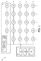
- Fig. 1 shows a networked lighting system 10, which comprises a lighting controller 14 and a network of several luminaries 22, for example installed in an office.
- the lighting controller 14 can transmit a message to each of the luminaries 22, which may comprise control information for the luminary 22, addressed by the message.
- the control information may comprise a command for a desired light setting of the addressed luminary 22, for example to set its lighting intensity to a certain level.
- the lighting controller 14 which may be implemented for example by a PC (Personal Computer) configured with a dedicated software for lighting control, comprises a memory 16 (for example a ROM, RAM, Flash, SSD, HDD, CD, DVD) storing the software and a processor 18 (for example a standard PC processor or a special microcontroller for lighting systems) configured by the software to control the lighting created by the luminaries 22.
- the lighting controller 14 further comprises a transmitter 20 for transmitting messages over the network to the luminaries 22.
- the transmitter 20 may be for example adapted to communicate according to a wired or wireless communication technology, particularly according to one or more of the following standards or technologies: ZigBeeTM, WiFiTM, Bluetooth®, Ethernet, DALI, IP enabled network such as 6LoWPAN/CoRE.
- Each of the luminaries 22 is adapted to receive messages from the lighting controller and to set its lighting in accordance with a control information contained in a received message.
- a luminary 22 comprises a receiver 24.
- a luminary 22 further comprises a memory 28 (for example a ROM, RAM, Flash) and a controller 26 (for example a microcontroller) configured by a program stored in the memory to process received messages and to set a lighting created by the luminary 22 in accordance with a control information contained in the processed message and obtained by the message processing.
- each luminary 22 has an unique address, for example a MAC (Medium Access Control)-Layer address, or an IP address if the network of the system 10 is an IP based network.
- the address of each luminary 22 of system 10 can be related to a logical ordering of the luminaries, as indicated in Fig. 1 by the matrix arrangement of the luminaries and the column (1-5) and line (A-E) indices: for example the luminary 22 arranged in the lower left corner of the matrix has the logical position "E1" in the matrix, while the luminary 22 in the upper right corner has the logical position "A5".
- the relation between the addresses and logical positions of the luminaries 22 can be stored in the lighting controller 14, for example during commissioning of the system 10.
- luminary information may relate to parameters inherent to the luminaire and its configuration such as the orientation of the luminaire (e.g., pointing to a wall or to the floor), the angle with respect to the perpendicular to the ceiling, the width of the light beam if the luminaire allows for an adaptive beam width, the type of luminaire.
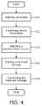
- Fig. 4 showing a flowchart of a method for controlling the luminaries.
- the method can be executed by the lighting controller 14 and implemented by a program stored in the memory 16 and exectued by the processor 18 of the controller 14.
- the luminaries 22 in line "A" are selected for control and grouped together (reference numeral 12; step S10 of the methodf of Fig. 4 ).
- Control information for the luminaries of the group 12 of selected luminaries is combined to a set of control information in step S12.
- a predetermined function for compressing the set of control information is selected in step S14.
- This predetermined function may depend on parameters that are computed to fit the specific lighting needs.
- the parameters can be computed with a computer program for lighting control in a light environment.
- the program may comprise a target light distribution for the light environment.
- Lighting settings of light sources may be calculated by an optimization process for a number of parameters to obtain the target light distribution in the light environment.
- a modelling process may model the lighting settings of the light sources as a function dependent on a number of parameters.
- the predetermined function associates an input related to a selected luminary, for example the network address or the logical position, to the control information for the luminary from the set of control information.
- a multicast message is created in step S16, which is addressed to the selected luminaries 12 and in step S 18 transmitted to the selected luminaries 12 over the network of the system 10 using the applied network protocol, for example IP or ZigBeeTM.
- a luminary 22 processes a received multicast message as briefly outlined in the following: it determines information regarding the selected predetermined function from the multicast message by processing the payload of the message, which contains either the function itself or an indication to the function. If it contains an indication to the function, the luminary 22 loads from its internal storage the indicated predetermined function. Next, the luminary 22 determines control information from the predetermined function by using an input related to the luminary.
- the input can be for example derived from a position information contained in the message, for example the position of a leading luminary for the control, or the input can be the luminaries' logical position in the networked lighting system, or its absolute position determined by GPS coordinates or its network address (for example IP- or MAC-address).
- the luminary calculates by using the determined input and the predetermined function its control information, for example its light settings such as intensity values.
- aspects 1 and 2 provides various ways to specify commands to be used in a lighting control standard that uses multicast (or broadcast) to set the light levels at the luminaires to individual, differentiated, values.
- the various combinations differ in versatility and efficiency, and ease of use.
- Aspect 2 considers addresses to use in evaluating the function.
- the hardware of a luminairy usually provides a hardware address for the device (e.g. a MAC address). Another option is obtained using the addresses that are generated when commissioning the system. These addresses may be related to the physical position of the luminaire in a space, or more related to a logical ordering of the luminaires (e.g. the logical addresses as used in the system shown in Fig. 1 ). Options for such addresses are listed in the following:
- the command of the multicast message specifies an origin for the function, and a luminaire uses its coordinates relative to this origin. Also, a function of its coordinates and the origin can be used, such as the distance to the origin.
- the luminaire When establishing a multicast group, it may be possible to order the luminaires in the group, and the luminaire can use its pre-fixed order when evaluating the function.
- luminaries are arranged in some repetitive pattern such as a linear arrangement (e.g. outdoor), a grid (e.g. office environment, refer to Fig. 1 ), or a (hierarchical or hexagonal) grid. It is possible to allocate a logical address to a luminaire in such a regular arrangement based on is position (e.g. its coordinates in the grid, or its sequence number in a linear arrangement). This logical location can then be used.
- the command may specify a logical origin for the function, and the luminaire uses its logical coordinates relative to this logical origin. Also, a function of its coordinates and the origin can be used, such as the distance to the origin.
- the function can be parameterised, so that the command additionally includes parameters.
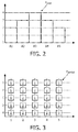
- the function can be a step function. As light settings are expected to vary smoothly over luminaires that are close to each other such a step function may be efficiently coded by specifying the start value and a difference between successive values (as shown for example in Fig. 2 ).
- the function can be specified via a polynomial. Polynomials of low degree are preferred to reduce the communication requirements, but the invention is not limited to them
- the function can be a periodic function so that the basic function is provided together with other parameters such as direction or period (as shown for example in Fig. 3 ).
- Fig. 2 shows the graph of a step function F step in one dimension as an example of a predetermined function.
- This function can be selected for adjusting the lighting intensity of the group 12 of luminaries 22 in the system shown in Fig. 1 (input of the function is the logical position of the luminary of the group 12, the output of the function is the intensity level).
- the only information contained in the multicast message must be either the step-function itselft or an indication to the step-function and the logical position "A3".
- a luminary of the group 12 receives the multicast message, it can adjust its lighting intensity depending on its position and in accordance with the step-function. This is shown by the graph of Fig.
- step -1 the luminary at the logical position "A3" adjust its intensity level to the maximum "4"
- one multicast/groupocast message is sent to the group 22 of luminaries, which contains less information than a multicast/groupcast message containing simply all logical positions and repective intensity values of the luminaries of the group 22.
- a predetermined periodic function F period is shown in Fig. 3 .
- This function can be selected to adjust the intensity levels of all luminaries of the system 10 with one command.
- a multicast message must only contain either the periodic function itself or an indication to the periodic function and the column 1 as start for the periodicity.
- a luminary receives the multicast message, it can determine its intensity level from the periodic function and the start column.
- all luminaries at the logical positions "A1" to “E1", “A3” to “E3”, and “A5" to “E5" can determine from the periodic function and their columns “1", “3” and “5" that their lighting intensity should be set to “0”, while the luminaries at the logical positions "A2" to “E2” and “A4" to “E4" can determine from the periodic function and their columns “2" and “4" that their lighting intensity should be set to "2".
- each luminaire will automatically adapt its light settings depending on the time, the room temperature, and external light temperature (contextual properties).
- the same function allows each luminaire to choose specific light settings depending on its location (x,y).
- the specific coefficients associated to those location variables can be dependent, e.g., on the specific distribution of windows in the room that require more light in those positions with a high x or y value.
- a message comprises a header and a payload.
- the header includes fields such as destination address and the payload includes the transported information.
- a multicast address is defined, which can be used by a node to decide whether a message is destined for it or not. This can be done by constructing the destination address contained in the header of a message as depicted below.
- Type message would represent the type of address (unicast, multicast, broadcast). Two bits can be used for this. For instance, 00 can be used to identify unicast messages within a network; 01 for multicast messages, and 11 for broadcast messages.
- the two additional fields "X" and "Y” might identify the X and Y coordinates of leading luminary defining, e.g., the origin of the function F used to create a personalized light spot around coordinate (x,y).
- These two fields can contain a logical position of a lamp or luminary or an absolute position such as GPS coordinates.
- the field “Features” defines specific characteristics of the multicast address. For instance, if a personalize light spot around luminaire (x,y) of width W is defined, the field “Features” could include a first subfield to identify the type of multicast (e.g., personalized light spot) followed by another field indicating the width. This is depicted below. Multicast type Width
- Such a construction can be applied to existing wireless communication protocols such as ZigBeeTM or 6LoWPAN.
- 6LoWPAN a lighting IP network can be defined in which all the devices have the same network prefix in the address.
- unicast addresses have a zero identifying the unicast messages.
- the invention can be applied to networked lighting systems and used to improve the control of a networked lighting system in that an efficient message format is defined to control several luminaries of a networked lighting system.
- the invention is the basis for a (set of) standardized command(s) or messages in a lighting control standard such as ZigBeeTM or 6LoWPAN. Many deployment scenarios would benefit by the availability of such a command or message.
- At least some of the functionality of the invention may be performed by hard- or software.
- a single or multiple standard microprocessors or microcontrollers may be used to process a single or multiple algorithms implementing the invention.
Landscapes
- Engineering & Computer Science (AREA)
- Computer Networks & Wireless Communication (AREA)
- Signal Processing (AREA)
- Health & Medical Sciences (AREA)
- Computing Systems (AREA)
- General Health & Medical Sciences (AREA)
- Medical Informatics (AREA)
- Automation & Control Theory (AREA)
- Circuit Arrangement For Electric Light Sources In General (AREA)
Priority Applications (1)
| Application Number | Priority Date | Filing Date | Title |
|---|---|---|---|
| EP11801855.5A EP2656692B1 (en) | 2010-12-22 | 2011-12-09 | Control of network lighting systems |
Applications Claiming Priority (3)
| Application Number | Priority Date | Filing Date | Title |
|---|---|---|---|
| EP10196515 | 2010-12-22 | ||
| EP11801855.5A EP2656692B1 (en) | 2010-12-22 | 2011-12-09 | Control of network lighting systems |
| PCT/IB2011/055570 WO2012085738A1 (en) | 2010-12-22 | 2011-12-09 | Control of network lighting systems |
Publications (2)
| Publication Number | Publication Date |
|---|---|
| EP2656692A1 EP2656692A1 (en) | 2013-10-30 |
| EP2656692B1 true EP2656692B1 (en) | 2016-11-16 |
Family
ID=45406807
Family Applications (1)
| Application Number | Title | Priority Date | Filing Date |
|---|---|---|---|
| EP11801855.5A Active EP2656692B1 (en) | 2010-12-22 | 2011-12-09 | Control of network lighting systems |
Country Status (6)
| Country | Link |
|---|---|
| US (2) | US9521731B2 (enExample) |
| EP (1) | EP2656692B1 (enExample) |
| JP (1) | JP5850948B2 (enExample) |
| CN (1) | CN103329629B (enExample) |
| TW (1) | TW201238404A (enExample) |
| WO (1) | WO2012085738A1 (enExample) |
Cited By (1)
| Publication number | Priority date | Publication date | Assignee | Title |
|---|---|---|---|---|
| US11172564B2 (en) * | 2018-03-02 | 2021-11-09 | SILVAIR Sp. z o.o. | Method for commissioning mesh network-capable devices, including mapping of provisioned nodes |
Families Citing this family (38)
| Publication number | Priority date | Publication date | Assignee | Title |
|---|---|---|---|---|
| TWI584682B (zh) * | 2008-04-09 | 2017-05-21 | 艾杜雷控股有限公司 | 廣播控制之可配置燈光裝置 |
| WO2010077244A1 (en) | 2008-12-30 | 2010-07-08 | C.R. Bard Inc. | Marker delivery device for tissue marker placement |
| US20130272125A1 (en) * | 2010-12-22 | 2013-10-17 | Koninklijke Philips N.V. | Component, system and method for controlling communication of data of at least one application of a communications network |
| RU2623491C2 (ru) | 2012-02-16 | 2017-06-27 | Филипс Лайтинг Холдинг Б.В. | Устройство и способы конфигурации освещения с использованием датчиков расстояния |
| DE102013203879B4 (de) * | 2013-03-07 | 2025-08-28 | Zumtobel Lighting Gmbh | Verfahren und System zum Ansteuern einer Gruppe von Leuchten bzw. steuerbaren Teileinheiten einer Leuchte |
| EP3097748A1 (en) | 2014-01-22 | 2016-11-30 | iLumisys, Inc. | Led-based light with addressed leds |
| JP6564387B2 (ja) * | 2014-02-25 | 2019-08-21 | シグニファイ ホールディング ビー ヴィ | ネットワーク化光源の照明効果を無線で制御する方法及び装置 |
| CN103888908B (zh) * | 2014-02-26 | 2017-02-22 | 北京信惠宝科技有限公司 | 向未登录wi‑fi接入点的接收终端传送数据的方法和系统 |
| EP2914067B1 (en) * | 2014-02-27 | 2018-04-25 | Airbus Operations GmbH | Lighting system and method for controlling a lighting system |
| WO2015189118A1 (en) * | 2014-06-10 | 2015-12-17 | Koninklijke Philips N.V. | Demand response for networked distributed lighting systems |
| US10841070B2 (en) * | 2014-06-18 | 2020-11-17 | Qualcomm Incorporated | Apparatus and method for capability update in wireless communication |
| US10172216B2 (en) | 2014-09-25 | 2019-01-01 | Philips Lighting Holding B.V. | Control of networked lighting devices |
| AT14699U1 (de) * | 2014-10-30 | 2016-04-15 | Tridonic Gmbh & Co Kg | Verfahren zur Ansteuerung für ein Betriebsgerät für Leuchtmittel |
| WO2016071432A1 (en) * | 2014-11-07 | 2016-05-12 | Philips Lighting Holding B.V. | Synchronous control of networked lighting devices |
| US10693714B2 (en) | 2015-05-29 | 2020-06-23 | Espressif Systems (Shanghai) Pte Ltd | Communication method for Wi-Fi internet of things equipment and Wi-Fi internet of things system |
| CN104883724B (zh) * | 2015-05-29 | 2018-08-14 | 乐鑫信息科技(上海)有限公司 | 一种Wi-Fi物联网设备通信方法及Wi-Fi物联网系统 |
| WO2016192387A1 (zh) | 2015-05-29 | 2016-12-08 | 乐鑫信息科技(上海)有限公司 | 一种安全低功耗代理设备的物联网配置方法及系统 |
| JP2017010814A (ja) * | 2015-06-23 | 2017-01-12 | 富士通コンポーネント株式会社 | 受信装置及び位置特定システム |
| RU2719502C2 (ru) * | 2015-07-06 | 2020-04-20 | Филипс Лайтинг Холдинг Б.В. | Сигнализация присутствия посредством сообщений в беспроводной сетевой световой системе |
| CN104994530B (zh) * | 2015-07-09 | 2019-01-15 | 乐鑫信息科技(上海)有限公司 | 基于组MAC地址的多Wi-Fi物联网设备分组集体控制系统及方法 |
| ES2906225T3 (es) * | 2015-07-14 | 2022-04-13 | Signify Holding Bv | Procedimiento para configurar un dispositivo en un sistema de iluminación |
| KR101842509B1 (ko) * | 2015-12-31 | 2018-05-14 | 한국산업기술대학교산학협력단 | 전등 위치 설정 방법 및 그 방법을 수행하는 전등 제어 시스템 |
| US9655215B1 (en) * | 2016-02-11 | 2017-05-16 | Ketra, Inc. | System and method for ensuring minimal control delay to grouped illumination devices configured within a wireless network |
| US9655214B1 (en) | 2016-02-11 | 2017-05-16 | Ketra, Inc. | Device, system and method for controlling visual content loaded into a grouped set of illumination devices configured within a wireless network |
| WO2017137413A1 (en) * | 2016-02-14 | 2017-08-17 | Philips Lighting Holding B.V. | Lighting control data identification. |
| GB2550220B (en) | 2016-05-12 | 2022-02-16 | Tridonic Gmbh & Co Kg | Building technology network device and method for forwarding multi-cast messages in a network comprising lighting devices |
| EP3482534B1 (en) | 2016-07-05 | 2022-11-23 | Lutron Technology Company LLC | Controlling groups of electrical loads via multicast and/or unicast messages |
| US9883570B1 (en) | 2016-07-20 | 2018-01-30 | Abl Ip Holding Llc | Protocol for lighting control via a wireless network |
| WO2018039885A1 (zh) * | 2016-08-29 | 2018-03-08 | 深圳市一窗科技有限责任公司 | 一种灯具控制方法及系统、照明控制装置、服务器 |
| CN108282938A (zh) * | 2016-12-30 | 2018-07-13 | 欧普照明股份有限公司 | 一种照明控制系统 |
| CN110100503B (zh) * | 2017-01-02 | 2022-03-04 | 昕诺飞控股有限公司 | 用于控制led阵列的照明系统 |
| DE102017122296A1 (de) * | 2017-09-26 | 2019-03-28 | Herbert Waldmann Gmbh & Co. Kg | Verfahren zum Betrieb wenigstens einer Leuchte und Beleuchtungseinrichtung |
| US11096263B2 (en) * | 2019-04-22 | 2021-08-17 | Beatro Co., Ltd. | Method and device for controlling a plurality of wireless lighting devices |
| CN110087375B (zh) * | 2019-05-17 | 2021-03-19 | 厦门光莆电子股份有限公司 | 一种基于LoRa的照明控制系统及其照明控制方法 |
| CN116368947A (zh) | 2020-09-04 | 2023-06-30 | 昕诺飞控股有限公司 | 基于控制历史确定存在传感器或光开关的位置 |
| US11743995B2 (en) | 2020-10-02 | 2023-08-29 | Lutron Technology Company Llc | Load control on wired and wireless communication links |
| US12287105B2 (en) | 2021-07-13 | 2025-04-29 | SILVAIR Sp. z o.o. | Networked sensors integrated with heating, ventilation, and air conditioning (HVAC) systems |
| CN115665924B (zh) * | 2022-11-11 | 2025-08-19 | 深圳市芯宇昊科技有限公司 | 一种led灯串的灯点地址分配方法及装置 |
Family Cites Families (14)
| Publication number | Priority date | Publication date | Assignee | Title |
|---|---|---|---|---|
| US6525722B1 (en) * | 1995-08-04 | 2003-02-25 | Sun Microsystems, Inc. | Geometry compression for regular and irregular mesh structures |
| US7202613B2 (en) * | 2001-05-30 | 2007-04-10 | Color Kinetics Incorporated | Controlled lighting methods and apparatus |
| JP4432548B2 (ja) * | 2004-03-10 | 2010-03-17 | パナソニック電工株式会社 | 照明器具および照明制御システム |
| CA2595949C (en) | 2005-03-12 | 2009-10-06 | Lutron Electronics Co., Inc. | Handheld programmer for lighting control system |
| TWI455645B (zh) * | 2006-12-08 | 2014-10-01 | 皇家飛利浦電子股份有限公司 | 光源、照明器具及照明器具系統 |
| WO2008139360A1 (en) * | 2007-05-09 | 2008-11-20 | Koninklijke Philips Electronics N.V. | A method and a system for controlling a lighting system |
| CN101682962A (zh) | 2007-05-22 | 2010-03-24 | 皇家飞利浦电子股份有限公司 | 用于显示器设备的环境照明系统以及这种环境照明系统的操作方法 |
| JP4925330B2 (ja) * | 2007-10-19 | 2012-04-25 | パナソニック株式会社 | 負荷制御システム |
| WO2009076492A1 (en) * | 2007-12-13 | 2009-06-18 | Daniel John Julio | Lighting control architechture |
| TWI487430B (zh) * | 2008-01-15 | 2015-06-01 | 皇家飛利浦電子股份有限公司 | 光源 |
| TWI584682B (zh) | 2008-04-09 | 2017-05-21 | 艾杜雷控股有限公司 | 廣播控制之可配置燈光裝置 |
| WO2009156900A1 (en) | 2008-06-26 | 2009-12-30 | Koninklijke Philips Electronics N.V. | Illumination system with distributed intelligence |
| US9578722B2 (en) * | 2008-12-04 | 2017-02-21 | Philips Lighting Holding B.V. | Methods for selecting and controlling devices |
| DE102009007526B4 (de) | 2009-02-05 | 2017-10-12 | Osram Gmbh | Verfahren zur Ansteuerung eines Mehrzahl von Lichtquellen |
-
2011
- 2011-12-09 US US13/996,906 patent/US9521731B2/en active Active
- 2011-12-09 EP EP11801855.5A patent/EP2656692B1/en active Active
- 2011-12-09 CN CN201180061843.7A patent/CN103329629B/zh active Active
- 2011-12-09 JP JP2013545546A patent/JP5850948B2/ja active Active
- 2011-12-09 WO PCT/IB2011/055570 patent/WO2012085738A1/en not_active Ceased
- 2011-12-20 TW TW100147543A patent/TW201238404A/zh unknown
-
2016
- 2016-11-17 US US15/354,616 patent/US11147144B2/en not_active Expired - Fee Related
Cited By (1)
| Publication number | Priority date | Publication date | Assignee | Title |
|---|---|---|---|---|
| US11172564B2 (en) * | 2018-03-02 | 2021-11-09 | SILVAIR Sp. z o.o. | Method for commissioning mesh network-capable devices, including mapping of provisioned nodes |
Also Published As
| Publication number | Publication date |
|---|---|
| US9521731B2 (en) | 2016-12-13 |
| JP2014504437A (ja) | 2014-02-20 |
| JP5850948B2 (ja) | 2016-02-03 |
| US20170071048A1 (en) | 2017-03-09 |
| WO2012085738A1 (en) | 2012-06-28 |
| CN103329629A (zh) | 2013-09-25 |
| US11147144B2 (en) | 2021-10-12 |
| US20130285574A1 (en) | 2013-10-31 |
| TW201238404A (en) | 2012-09-16 |
| EP2656692A1 (en) | 2013-10-30 |
| CN103329629B (zh) | 2016-01-20 |
Similar Documents
| Publication | Publication Date | Title |
|---|---|---|
| EP2656692B1 (en) | Control of network lighting systems | |
| US10743390B2 (en) | Out-of-the-box commissioning of a control system | |
| US11677589B2 (en) | Devices, systems, and methods for controlling electrical loads | |
| US20120212140A1 (en) | Apparatus and method for controlling lighting based on dali communication | |
| CN101911835B (zh) | 一种光源 | |
| CN105007651B (zh) | 在广播控制下的可配置照明装置 | |
| TW200841767A (en) | A light source | |
| US11073809B2 (en) | Devices, systems, and methods for controlling electrical fixtures | |
| JP2014504437A5 (enExample) | ||
| CN103139320A (zh) | 将标识码指定给网络中的设备的方法 | |
| WO2018154433A1 (en) | A node for a multi-hop communication network, related lighting system, method of updating the software of lighting modules and computer-program product | |
| US20110280251A1 (en) | Apparatus having a fixture with an integrated gateway and methods thereof | |
| US20170055332A1 (en) | Illumination system | |
| JP6691755B2 (ja) | 通信システム、通信方法、照明制御システム、照明制御方法、及びプログラム | |
| JP2020149910A (ja) | 照明制御システム | |
| US12200845B2 (en) | Parallel repeater network formation | |
| WO2016043150A1 (ja) | 照明制御システム、通信システム、照明制御方法、通信方法、及びプログラム | |
| US20210037631A1 (en) | System and method for dynamic lighting using a narrowband wireless lighting network | |
| US10667359B2 (en) | Lighting system control based on lighting playlist | |
| van Bommel | Connected Smart Lighting | |
| Asgharian et al. | Implementing a ZigBee-Based Smart Lighting System |
Legal Events
| Date | Code | Title | Description |
|---|---|---|---|
| PUAI | Public reference made under article 153(3) epc to a published international application that has entered the european phase |
Free format text: ORIGINAL CODE: 0009012 |
|
| 17P | Request for examination filed |
Effective date: 20130722 |
|
| AK | Designated contracting states |
Kind code of ref document: A1 Designated state(s): AL AT BE BG CH CY CZ DE DK EE ES FI FR GB GR HR HU IE IS IT LI LT LU LV MC MK MT NL NO PL PT RO RS SE SI SK SM TR |
|
| DAX | Request for extension of the european patent (deleted) | ||
| GRAP | Despatch of communication of intention to grant a patent |
Free format text: ORIGINAL CODE: EPIDOSNIGR1 |
|
| INTG | Intention to grant announced |
Effective date: 20160610 |
|
| RAP1 | Party data changed (applicant data changed or rights of an application transferred) |
Owner name: PHILIPS LIGHTING HOLDING B.V. |
|
| GRAS | Grant fee paid |
Free format text: ORIGINAL CODE: EPIDOSNIGR3 |
|
| GRAA | (expected) grant |
Free format text: ORIGINAL CODE: 0009210 |
|
| AK | Designated contracting states |
Kind code of ref document: B1 Designated state(s): AL AT BE BG CH CY CZ DE DK EE ES FI FR GB GR HR HU IE IS IT LI LT LU LV MC MK MT NL NO PL PT RO RS SE SI SK SM TR |
|
| REG | Reference to a national code |
Ref country code: GB Ref legal event code: FG4D |
|
| REG | Reference to a national code |
Ref country code: CH Ref legal event code: EP |
|
| REG | Reference to a national code |
Ref country code: IE Ref legal event code: FG4D |
|
| REG | Reference to a national code |
Ref country code: AT Ref legal event code: REF Ref document number: 846977 Country of ref document: AT Kind code of ref document: T Effective date: 20161215 |
|
| REG | Reference to a national code |
Ref country code: DE Ref legal event code: R096 Ref document number: 602011032534 Country of ref document: DE Ref country code: FR Ref legal event code: PLFP Year of fee payment: 6 |
|
| PG25 | Lapsed in a contracting state [announced via postgrant information from national office to epo] |
Ref country code: LV Free format text: LAPSE BECAUSE OF FAILURE TO SUBMIT A TRANSLATION OF THE DESCRIPTION OR TO PAY THE FEE WITHIN THE PRESCRIBED TIME-LIMIT Effective date: 20161116 |
|
| REG | Reference to a national code |
Ref country code: NL Ref legal event code: MP Effective date: 20161116 |
|
| REG | Reference to a national code |
Ref country code: LT Ref legal event code: MG4D |
|
| REG | Reference to a national code |
Ref country code: AT Ref legal event code: MK05 Ref document number: 846977 Country of ref document: AT Kind code of ref document: T Effective date: 20161116 |
|
| PG25 | Lapsed in a contracting state [announced via postgrant information from national office to epo] |
Ref country code: LT Free format text: LAPSE BECAUSE OF FAILURE TO SUBMIT A TRANSLATION OF THE DESCRIPTION OR TO PAY THE FEE WITHIN THE PRESCRIBED TIME-LIMIT Effective date: 20161116 Ref country code: NL Free format text: LAPSE BECAUSE OF FAILURE TO SUBMIT A TRANSLATION OF THE DESCRIPTION OR TO PAY THE FEE WITHIN THE PRESCRIBED TIME-LIMIT Effective date: 20161116 Ref country code: NO Free format text: LAPSE BECAUSE OF FAILURE TO SUBMIT A TRANSLATION OF THE DESCRIPTION OR TO PAY THE FEE WITHIN THE PRESCRIBED TIME-LIMIT Effective date: 20170216 Ref country code: GR Free format text: LAPSE BECAUSE OF FAILURE TO SUBMIT A TRANSLATION OF THE DESCRIPTION OR TO PAY THE FEE WITHIN THE PRESCRIBED TIME-LIMIT Effective date: 20170217 Ref country code: SE Free format text: LAPSE BECAUSE OF FAILURE TO SUBMIT A TRANSLATION OF THE DESCRIPTION OR TO PAY THE FEE WITHIN THE PRESCRIBED TIME-LIMIT Effective date: 20161116 |
|
| PG25 | Lapsed in a contracting state [announced via postgrant information from national office to epo] |
Ref country code: AT Free format text: LAPSE BECAUSE OF FAILURE TO SUBMIT A TRANSLATION OF THE DESCRIPTION OR TO PAY THE FEE WITHIN THE PRESCRIBED TIME-LIMIT Effective date: 20161116 Ref country code: BE Free format text: LAPSE BECAUSE OF NON-PAYMENT OF DUE FEES Effective date: 20161231 Ref country code: PT Free format text: LAPSE BECAUSE OF FAILURE TO SUBMIT A TRANSLATION OF THE DESCRIPTION OR TO PAY THE FEE WITHIN THE PRESCRIBED TIME-LIMIT Effective date: 20170316 Ref country code: FI Free format text: LAPSE BECAUSE OF FAILURE TO SUBMIT A TRANSLATION OF THE DESCRIPTION OR TO PAY THE FEE WITHIN THE PRESCRIBED TIME-LIMIT Effective date: 20161116 Ref country code: ES Free format text: LAPSE BECAUSE OF FAILURE TO SUBMIT A TRANSLATION OF THE DESCRIPTION OR TO PAY THE FEE WITHIN THE PRESCRIBED TIME-LIMIT Effective date: 20161116 Ref country code: HR Free format text: LAPSE BECAUSE OF FAILURE TO SUBMIT A TRANSLATION OF THE DESCRIPTION OR TO PAY THE FEE WITHIN THE PRESCRIBED TIME-LIMIT Effective date: 20161116 Ref country code: RS Free format text: LAPSE BECAUSE OF FAILURE TO SUBMIT A TRANSLATION OF THE DESCRIPTION OR TO PAY THE FEE WITHIN THE PRESCRIBED TIME-LIMIT Effective date: 20161116 Ref country code: PL Free format text: LAPSE BECAUSE OF FAILURE TO SUBMIT A TRANSLATION OF THE DESCRIPTION OR TO PAY THE FEE WITHIN THE PRESCRIBED TIME-LIMIT Effective date: 20161116 |
|
| PG25 | Lapsed in a contracting state [announced via postgrant information from national office to epo] |
Ref country code: CZ Free format text: LAPSE BECAUSE OF FAILURE TO SUBMIT A TRANSLATION OF THE DESCRIPTION OR TO PAY THE FEE WITHIN THE PRESCRIBED TIME-LIMIT Effective date: 20161116 Ref country code: SK Free format text: LAPSE BECAUSE OF FAILURE TO SUBMIT A TRANSLATION OF THE DESCRIPTION OR TO PAY THE FEE WITHIN THE PRESCRIBED TIME-LIMIT Effective date: 20161116 Ref country code: DK Free format text: LAPSE BECAUSE OF FAILURE TO SUBMIT A TRANSLATION OF THE DESCRIPTION OR TO PAY THE FEE WITHIN THE PRESCRIBED TIME-LIMIT Effective date: 20161116 Ref country code: EE Free format text: LAPSE BECAUSE OF FAILURE TO SUBMIT A TRANSLATION OF THE DESCRIPTION OR TO PAY THE FEE WITHIN THE PRESCRIBED TIME-LIMIT Effective date: 20161116 Ref country code: RO Free format text: LAPSE BECAUSE OF FAILURE TO SUBMIT A TRANSLATION OF THE DESCRIPTION OR TO PAY THE FEE WITHIN THE PRESCRIBED TIME-LIMIT Effective date: 20161116 |
|
| REG | Reference to a national code |
Ref country code: CH Ref legal event code: PL |
|
| REG | Reference to a national code |
Ref country code: DE Ref legal event code: R097 Ref document number: 602011032534 Country of ref document: DE |
|
| PG25 | Lapsed in a contracting state [announced via postgrant information from national office to epo] |
Ref country code: IT Free format text: LAPSE BECAUSE OF FAILURE TO SUBMIT A TRANSLATION OF THE DESCRIPTION OR TO PAY THE FEE WITHIN THE PRESCRIBED TIME-LIMIT Effective date: 20161116 Ref country code: BE Free format text: LAPSE BECAUSE OF FAILURE TO SUBMIT A TRANSLATION OF THE DESCRIPTION OR TO PAY THE FEE WITHIN THE PRESCRIBED TIME-LIMIT Effective date: 20161116 Ref country code: SM Free format text: LAPSE BECAUSE OF FAILURE TO SUBMIT A TRANSLATION OF THE DESCRIPTION OR TO PAY THE FEE WITHIN THE PRESCRIBED TIME-LIMIT Effective date: 20161116 Ref country code: BG Free format text: LAPSE BECAUSE OF FAILURE TO SUBMIT A TRANSLATION OF THE DESCRIPTION OR TO PAY THE FEE WITHIN THE PRESCRIBED TIME-LIMIT Effective date: 20170216 |
|
| PLBE | No opposition filed within time limit |
Free format text: ORIGINAL CODE: 0009261 |
|
| STAA | Information on the status of an ep patent application or granted ep patent |
Free format text: STATUS: NO OPPOSITION FILED WITHIN TIME LIMIT |
|
| PG25 | Lapsed in a contracting state [announced via postgrant information from national office to epo] |
Ref country code: MC Free format text: LAPSE BECAUSE OF FAILURE TO SUBMIT A TRANSLATION OF THE DESCRIPTION OR TO PAY THE FEE WITHIN THE PRESCRIBED TIME-LIMIT Effective date: 20161116 |
|
| REG | Reference to a national code |
Ref country code: IE Ref legal event code: MM4A |
|
| 26N | No opposition filed |
Effective date: 20170817 |
|
| PG25 | Lapsed in a contracting state [announced via postgrant information from national office to epo] |
Ref country code: LI Free format text: LAPSE BECAUSE OF NON-PAYMENT OF DUE FEES Effective date: 20161231 Ref country code: LU Free format text: LAPSE BECAUSE OF NON-PAYMENT OF DUE FEES Effective date: 20161209 Ref country code: CH Free format text: LAPSE BECAUSE OF NON-PAYMENT OF DUE FEES Effective date: 20161231 |
|
| PG25 | Lapsed in a contracting state [announced via postgrant information from national office to epo] |
Ref country code: IE Free format text: LAPSE BECAUSE OF NON-PAYMENT OF DUE FEES Effective date: 20161209 Ref country code: SI Free format text: LAPSE BECAUSE OF FAILURE TO SUBMIT A TRANSLATION OF THE DESCRIPTION OR TO PAY THE FEE WITHIN THE PRESCRIBED TIME-LIMIT Effective date: 20161116 |
|
| REG | Reference to a national code |
Ref country code: FR Ref legal event code: PLFP Year of fee payment: 7 |
|
| PG25 | Lapsed in a contracting state [announced via postgrant information from national office to epo] |
Ref country code: HU Free format text: LAPSE BECAUSE OF FAILURE TO SUBMIT A TRANSLATION OF THE DESCRIPTION OR TO PAY THE FEE WITHIN THE PRESCRIBED TIME-LIMIT; INVALID AB INITIO Effective date: 20111209 Ref country code: CY Free format text: LAPSE BECAUSE OF FAILURE TO SUBMIT A TRANSLATION OF THE DESCRIPTION OR TO PAY THE FEE WITHIN THE PRESCRIBED TIME-LIMIT Effective date: 20161116 |
|
| PG25 | Lapsed in a contracting state [announced via postgrant information from national office to epo] |
Ref country code: MK Free format text: LAPSE BECAUSE OF FAILURE TO SUBMIT A TRANSLATION OF THE DESCRIPTION OR TO PAY THE FEE WITHIN THE PRESCRIBED TIME-LIMIT Effective date: 20161116 Ref country code: IS Free format text: LAPSE BECAUSE OF FAILURE TO SUBMIT A TRANSLATION OF THE DESCRIPTION OR TO PAY THE FEE WITHIN THE PRESCRIBED TIME-LIMIT Effective date: 20161116 |
|
| PG25 | Lapsed in a contracting state [announced via postgrant information from national office to epo] |
Ref country code: MT Free format text: LAPSE BECAUSE OF NON-PAYMENT OF DUE FEES Effective date: 20161209 |
|
| PG25 | Lapsed in a contracting state [announced via postgrant information from national office to epo] |
Ref country code: TR Free format text: LAPSE BECAUSE OF FAILURE TO SUBMIT A TRANSLATION OF THE DESCRIPTION OR TO PAY THE FEE WITHIN THE PRESCRIBED TIME-LIMIT Effective date: 20161116 |
|
| PG25 | Lapsed in a contracting state [announced via postgrant information from national office to epo] |
Ref country code: AL Free format text: LAPSE BECAUSE OF FAILURE TO SUBMIT A TRANSLATION OF THE DESCRIPTION OR TO PAY THE FEE WITHIN THE PRESCRIBED TIME-LIMIT Effective date: 20161116 |
|
| REG | Reference to a national code |
Ref country code: DE Ref legal event code: R082 Ref document number: 602011032534 Country of ref document: DE Representative=s name: MEISSNER BOLTE PATENTANWAELTE RECHTSANWAELTE P, DE Ref country code: DE Ref legal event code: R081 Ref document number: 602011032534 Country of ref document: DE Owner name: SIGNIFY HOLDING B.V., NL Free format text: FORMER OWNER: PHILIPS LIGHTING HOLDING B.V., EINDHOVEN, NL |
|
| P01 | Opt-out of the competence of the unified patent court (upc) registered |
Effective date: 20230421 |
|
| PGFP | Annual fee paid to national office [announced via postgrant information from national office to epo] |
Ref country code: GB Payment date: 20251223 Year of fee payment: 15 |
|
| PGFP | Annual fee paid to national office [announced via postgrant information from national office to epo] |
Ref country code: FR Payment date: 20251230 Year of fee payment: 15 |
|
| PGFP | Annual fee paid to national office [announced via postgrant information from national office to epo] |
Ref country code: DE Payment date: 20260220 Year of fee payment: 15 |