EP2656526B1 - Réseau de communication utilisant une correction d'erreurs sans voie de retour (fec) adaptable - Google Patents
Réseau de communication utilisant une correction d'erreurs sans voie de retour (fec) adaptable Download PDFInfo
- Publication number
- EP2656526B1 EP2656526B1 EP11708257.8A EP11708257A EP2656526B1 EP 2656526 B1 EP2656526 B1 EP 2656526B1 EP 11708257 A EP11708257 A EP 11708257A EP 2656526 B1 EP2656526 B1 EP 2656526B1
- Authority
- EP
- European Patent Office
- Prior art keywords
- node
- error correction
- frames
- correction part
- rate
- Prior art date
- Legal status (The legal status is an assumption and is not a legal conclusion. Google has not performed a legal analysis and makes no representation as to the accuracy of the status listed.)
- Not-in-force
Links
- 238000004891 communication Methods 0.000 title claims description 23
- 238000012937 correction Methods 0.000 claims description 80
- 230000003287 optical effect Effects 0.000 claims description 72
- 230000005540 biological transmission Effects 0.000 claims description 57
- 238000000034 method Methods 0.000 claims description 21
- 230000006978 adaptation Effects 0.000 claims description 13
- 238000012544 monitoring process Methods 0.000 claims description 11
- 230000004044 response Effects 0.000 claims description 4
- 238000012545 processing Methods 0.000 description 15
- 230000006870 function Effects 0.000 description 8
- 230000009471 action Effects 0.000 description 4
- 238000006243 chemical reaction Methods 0.000 description 4
- 239000000835 fiber Substances 0.000 description 3
- 230000001965 increasing effect Effects 0.000 description 3
- 101100406673 Arabidopsis thaliana OTU3 gene Proteins 0.000 description 2
- 230000003044 adaptive effect Effects 0.000 description 2
- 230000008859 change Effects 0.000 description 2
- 230000003247 decreasing effect Effects 0.000 description 2
- 238000005516 engineering process Methods 0.000 description 2
- 238000009432 framing Methods 0.000 description 2
- 239000000243 solution Substances 0.000 description 2
- 101000822695 Clostridium perfringens (strain 13 / Type A) Small, acid-soluble spore protein C1 Proteins 0.000 description 1
- 101000655262 Clostridium perfringens (strain 13 / Type A) Small, acid-soluble spore protein C2 Proteins 0.000 description 1
- 101000655256 Paraclostridium bifermentans Small, acid-soluble spore protein alpha Proteins 0.000 description 1
- 101000655264 Paraclostridium bifermentans Small, acid-soluble spore protein beta Proteins 0.000 description 1
- 238000007792 addition Methods 0.000 description 1
- 230000002776 aggregation Effects 0.000 description 1
- 238000004220 aggregation Methods 0.000 description 1
- 230000004075 alteration Effects 0.000 description 1
- 238000004590 computer program Methods 0.000 description 1
- 230000007547 defect Effects 0.000 description 1
- 239000006185 dispersion Substances 0.000 description 1
- 230000000694 effects Effects 0.000 description 1
- 230000002708 enhancing effect Effects 0.000 description 1
- RGNPBRKPHBKNKX-UHFFFAOYSA-N hexaflumuron Chemical compound C1=C(Cl)C(OC(F)(F)C(F)F)=C(Cl)C=C1NC(=O)NC(=O)C1=C(F)C=CC=C1F RGNPBRKPHBKNKX-UHFFFAOYSA-N 0.000 description 1
- 230000010365 information processing Effects 0.000 description 1
- 230000010354 integration Effects 0.000 description 1
- 238000013507 mapping Methods 0.000 description 1
- 230000007246 mechanism Effects 0.000 description 1
- 238000012986 modification Methods 0.000 description 1
- 230000004048 modification Effects 0.000 description 1
- 230000001151 other effect Effects 0.000 description 1
- 239000012086 standard solution Substances 0.000 description 1
- 230000007704 transition Effects 0.000 description 1
Images


Classifications
-
- H—ELECTRICITY
- H04—ELECTRIC COMMUNICATION TECHNIQUE
- H04L—TRANSMISSION OF DIGITAL INFORMATION, e.g. TELEGRAPHIC COMMUNICATION
- H04L1/00—Arrangements for detecting or preventing errors in the information received
- H04L1/004—Arrangements for detecting or preventing errors in the information received by using forward error control
- H04L1/0041—Arrangements at the transmitter end
-
- H—ELECTRICITY
- H04—ELECTRIC COMMUNICATION TECHNIQUE
- H04L—TRANSMISSION OF DIGITAL INFORMATION, e.g. TELEGRAPHIC COMMUNICATION
- H04L1/00—Arrangements for detecting or preventing errors in the information received
- H04L1/0001—Systems modifying transmission characteristics according to link quality, e.g. power backoff
- H04L1/0009—Systems modifying transmission characteristics according to link quality, e.g. power backoff by adapting the channel coding
-
- H—ELECTRICITY
- H04—ELECTRIC COMMUNICATION TECHNIQUE
- H04B—TRANSMISSION
- H04B10/00—Transmission systems employing electromagnetic waves other than radio-waves, e.g. infrared, visible or ultraviolet light, or employing corpuscular radiation, e.g. quantum communication
- H04B10/07—Arrangements for monitoring or testing transmission systems; Arrangements for fault measurement of transmission systems
- H04B10/075—Arrangements for monitoring or testing transmission systems; Arrangements for fault measurement of transmission systems using an in-service signal
- H04B10/079—Arrangements for monitoring or testing transmission systems; Arrangements for fault measurement of transmission systems using an in-service signal using measurements of the data signal
- H04B10/0795—Performance monitoring; Measurement of transmission parameters
- H04B10/07953—Monitoring or measuring OSNR, BER or Q
-
- H—ELECTRICITY
- H04—ELECTRIC COMMUNICATION TECHNIQUE
- H04J—MULTIPLEX COMMUNICATION
- H04J14/00—Optical multiplex systems
- H04J14/02—Wavelength-division multiplex systems
- H04J14/0201—Add-and-drop multiplexing
- H04J14/0202—Arrangements therefor
- H04J14/021—Reconfigurable arrangements, e.g. reconfigurable optical add/drop multiplexers [ROADM] or tunable optical add/drop multiplexers [TOADM]
- H04J14/0212—Reconfigurable arrangements, e.g. reconfigurable optical add/drop multiplexers [ROADM] or tunable optical add/drop multiplexers [TOADM] using optical switches or wavelength selective switches [WSS]
-
- H—ELECTRICITY
- H04—ELECTRIC COMMUNICATION TECHNIQUE
- H04J—MULTIPLEX COMMUNICATION
- H04J14/00—Optical multiplex systems
- H04J14/02—Wavelength-division multiplex systems
- H04J14/0221—Power control, e.g. to keep the total optical power constant
-
- H—ELECTRICITY
- H04—ELECTRIC COMMUNICATION TECHNIQUE
- H04J—MULTIPLEX COMMUNICATION
- H04J14/00—Optical multiplex systems
- H04J14/02—Wavelength-division multiplex systems
- H04J14/0227—Operation, administration, maintenance or provisioning [OAMP] of WDM networks, e.g. media access, routing or wavelength allocation
- H04J14/0254—Optical medium access
- H04J14/0272—Transmission of OAMP information
- H04J14/0273—Transmission of OAMP information using optical overhead, e.g. overhead processing
-
- H—ELECTRICITY
- H04—ELECTRIC COMMUNICATION TECHNIQUE
- H04L—TRANSMISSION OF DIGITAL INFORMATION, e.g. TELEGRAPHIC COMMUNICATION
- H04L1/00—Arrangements for detecting or preventing errors in the information received
- H04L1/004—Arrangements for detecting or preventing errors in the information received by using forward error control
- H04L1/0045—Arrangements at the receiver end
-
- H—ELECTRICITY
- H04—ELECTRIC COMMUNICATION TECHNIQUE
- H04L—TRANSMISSION OF DIGITAL INFORMATION, e.g. TELEGRAPHIC COMMUNICATION
- H04L1/00—Arrangements for detecting or preventing errors in the information received
- H04L1/20—Arrangements for detecting or preventing errors in the information received using signal quality detector
- H04L1/203—Details of error rate determination, e.g. BER, FER or WER
-
- H—ELECTRICITY
- H04—ELECTRIC COMMUNICATION TECHNIQUE
- H04J—MULTIPLEX COMMUNICATION
- H04J2203/00—Aspects of optical multiplex systems other than those covered by H04J14/05 and H04J14/07
- H04J2203/0001—Provisions for broadband connections in integrated services digital network using frames of the Optical Transport Network [OTN] or using synchronous transfer mode [STM], e.g. SONET, SDH
- H04J2203/0057—Operations, administration and maintenance [OAM]
- H04J2203/006—Fault tolerance and recovery
-
- H—ELECTRICITY
- H04—ELECTRIC COMMUNICATION TECHNIQUE
- H04J—MULTIPLEX COMMUNICATION
- H04J2203/00—Aspects of optical multiplex systems other than those covered by H04J14/05 and H04J14/07
- H04J2203/0001—Provisions for broadband connections in integrated services digital network using frames of the Optical Transport Network [OTN] or using synchronous transfer mode [STM], e.g. SONET, SDH
- H04J2203/0089—Multiplexing, e.g. coding, scrambling, SONET
-
- H—ELECTRICITY
- H04—ELECTRIC COMMUNICATION TECHNIQUE
- H04L—TRANSMISSION OF DIGITAL INFORMATION, e.g. TELEGRAPHIC COMMUNICATION
- H04L1/00—Arrangements for detecting or preventing errors in the information received
- H04L1/0001—Systems modifying transmission characteristics according to link quality, e.g. power backoff
- H04L1/0023—Systems modifying transmission characteristics according to link quality, e.g. power backoff characterised by the signalling
- H04L1/0026—Transmission of channel quality indication
Definitions
- This invention relates to nodes for communications networks, operable as source nodes or as sink nodes, to methods of using such nodes, and to corresponding computer programs for controlling such nodes, and in particular embodiments to optical transport networks of the type described in the G.709 and related standards.
- WDM wavelength division multiplexing
- DWDM dense wavelength division multiplexing
- AVGs arrayed waveguide gratings
- FGs fibergratings
- DWDM does not provide its own overhead for management nor protection schemes to recover from equipment failures.
- DWDM involves more network elements than earlier point to point optical links.
- Such elements such as-optical amplifiers, multiplexers, and demultiplexers-and dispersion compensation units, can bring reliability concerns and warrant monitoring.
- the G.709 Optical Transport Network, or OTN standard was generated by the International Telecommunication Union Telecommunication Standardization (ITU-T) to provide management functionality for DWDM optical networks.
- ITU-T International Telecommunication Union Telecommunication Standardization
- OTN involves adding a frame of overhead information, (also called a digital wrapper), some to the front of the signal as a header, and some such as FEC (Forward Error Correction) as a trailer appended to the rear.
- FEC Forward Error Correction
- the FEC can extend optical span distances by reducing bit error rates (BERs).
- FEC is one of the most attractive features provided by G.709 Hierarchy. It allows the receiver to detect and correct errors and therefore permits the transmission of data along "disturbed" paths or to reach a longer distance than an equivalent signal without this feature. Therefore the FEC can improve the quality of the transmission but its deployment has a cost.
- EP 1,981,202 describes a method for communication including transmitting data from a transmitter to a receiver using Adaptive Coding and Modulation (ACM).
- ACM Adaptive Coding and Modulation
- the data rate is set by selecting, based on feedback, an ACM profile defining a Forward Error Correction code and a modulation scheme.
- an operation of the transmitter is changed independently of the feedback.
- WO 2009/134220 describes receiving channel condition feedback from a device over a wireless channel, determining, based on the received feedback, whether the device can be served, determining if a forward error correction coding rate is sufficient for the device to recover lost data, adjusting the forward error correction coding rate responsive to the second determining act and generating forward error correction packets using forward error correction coding rate from said source data.
- US 2006/188035 describes adapting the system bit rate on-line in a seamless manner.
- the system provides a framing and encoding method with reduced overhead.
- An object of the invention is to provide improved apparatus or methods.
- the invention provides: A node for a communications network, the node being operable as a sink node and having a converter for digitizing at a receiver clock rate a received optical signal received over an optical link from an optical transmitter at another node, a framer for detecting frames in the digital data, the frames each having a payload part, and a forward error correction part.
- the node also has an error corrector for correcting errors in the payload part using the forward error correction part of the frame, a monitor for monitoring an error rate in the received payload part, and a processor.
- the processor is arranged to send, according to the monitored error rate, a request to the optical transmitter to adapt a length of the transmitted forward error correction part and to adapt a clock rate of the transmission of the frame.
- This means a reduced clock rate is possible when FEC is reduced or disabled, which can enable power saving at the transmitter (source) or at both the transmitter and the receiver (sink), when less FEC is needed.
- a node for a communications network operable as a source node and having an optical transmitter for transmitting an optical signal over an optical link to another node, and a framer for outputting frames having a payload part and an error correction part at a first clock rate.
- the node also has a converter for converting the frames into the optical signal for transmission, and a processor arranged to receive a request to adapt the size of the transmitted forward error correction part and in response to adapt a length of the error correction part in the frames, and adapt a clock rate of the framer.
- Another aspect of the invention provides a method of transmitting a payload of data from a first node of a communications network, and acting as a source node, to a second node acting as a sink node, the method having the steps of transmitting frames of data from the source node, the frames each having a payload part, and a forward error correction part, and receiving at the source node a request from the sink node.
- the request is to adapt a length of the transmitted forward error correction part according to a monitored error rate and to adapt a clock rate of the transmission of the frame, according to the adapted length of the forward correction part.
- the length of the forward error correction part in each frame is then adapted.
- Another aspect of the invention provides a method of receiving a payload of data sent from a first node of a communications network acting as a source node, to a second node acting as a sink node, the method having the steps of, receiving at the sink node frames of data from the source node, the frames each having a payload part, and a forward error correction part, correcting errors in the payload part using the forward error correction part of the frame, and monitoring an error rate in the received payload part.
- a request is sent to the source to adapt a length of the transmitted forward error correction part according to the monitored error rate and to adapt a clock rate of the transmission of the frame, according to the adapted amount of the forward correction part.
- the data is received at the adapted clock rate of the transmitter and with an adapted length of the forward error correction part in each frame.
- Another aspect of the invention provides a method of transmitting a payload of data from a first node of a communications network acting as a source node to a second node acting as a sink node, the method having the steps of transmitting frames of data from the source node, the frames each having a payload part, and a forward error correction part, at the sink node, receiving the data, correcting errors in the payload part using the forward error correction part of the frame, and monitoring an error rate in the received payload part.
- the method also involves sending a request to the source to adapt a length of the transmitted forward error correction part according to the monitored error rate and to adapt a clock rate of the transmission of the frame, according to the adapted amount of the forward correction part, at the source node, adapting the length of the forward error correction part in each frame, and at the sink node, continuing to receive the frames of data having the adapted length of the forward error correction part in each frame.
- Another aspect of the invention provides a computer readable storage medium having a stored program for execution by a processor for controlling a node for a communications network, the node acting as a sink node and having a converter for digitizing at a receiver clock rate a received optical signal received over an optical link from an optical transmitter at another node, a framer for detecting frames in the digital data, the frames each having a payload part, and a forward error correction part, the node also having an error corrector for correcting errors in the payload part using the forward error correction part of the frame, and a monitor for monitoring an error rate in the received payload part.
- the program has instructions which when executed by the processor cause the processor to carry out the steps of receiving a monitored error rate from the monitor, sending, according to the monitored error rate, a request to the transmitter to adapt a length of the transmitted forward error correction part and to adapt a clock rate of the transmission of the frame.
- Another aspect provides a computer readable storage medium having a stored program for execution by a processor for controlling a node for a communications network, the node acting as a source node and having an optical transmitter for transmitting an optical signal over an optical link to another node, the node also having a framer for outputting frames having a payload part and an error correction part at a first clock rate, a converter for converting the frames into the optical signal for transmission, and a processor arranged to receive a request to adapt the size of the transmitted forward error correction part and in response to adapt a length of the error correction part in the frames, and adapt a clock rate of the framer.
- the program has instructions which when executed by the processor cause the processor to carry out the steps of causing the optical transmitter to transmit frames of data, the frames each having a payload part, and a forward error correction part, receiving a request from the sink node to adapt a length of the transmitted forward error correction part according to a monitored error rate and causing the optical transmitter to adapt a clock rate of the transmission of the frame, according to the adapted length the forward correction part, and at the source node, adapting the length of the forward error correction part in each frame.
- Elements or parts of the described nodes or networks may comprise logic encoded in media for performing any kind of information processing.
- Logic may comprise software encoded in a disk or other computer-readable medium and/or instructions encoded in an application specific integrated circuit (ASIC), field programmable gate array (FPGA), or other processor or hardware.
- ASIC application specific integrated circuit
- FPGA field programmable gate array
- references to nodes can encompass any kind of switching node, not limited to the types described, not limited to any level of integration, or size or bandwidth or bit rate and so on.
- references to software can encompass any type of programs in any language executable directly or indirectly on processing hardware.
- references processors or circuitry can encompass any kind of logic or analog circuitry, integrated to any degree, and not limited to general purpose processors, digital signal processors, ASICs, FPGAs, discrete components or logic and so on.
- references to a storage medium are intended to encompass storage in non transitory form not including a signal passing along a communications path.
- Embodiments of the present invention can reduce the power consumption in data transport equipment, by adapting the FEC. This is particularly applicable in equipment based on G.709/G.798 OTN technology.
- FEC has a cost in term of bandwidth occupation.
- OTUk frame i.e. the frame used for the transport of data trough the physical links
- this occupation can be even more (e.g. 20%).
- the clock of the transmitter would be increased by 7-20%, depending on the type of FEC used, compared to the same link using the same quantity of information but without FEC.
- the power consumption of digital processing tends to increase with the square of the clock speed, even a modest change in clock speed could make a notable difference to power consumption. This means that the transmission of the same quantity of data using FEC requires more power than a transmission without FEC.
- FEC processing consumes a lot of resources also in computation capability (e.g. number of gates required in the ASSP/ASIC/FPGA implementing the G.709 processing) and therefore in power consumption.
- the FEC encoding is always enabled (See Sect.12.3.1.1: OCh/OTUk-a_A_So function), though the operator can decide to enable/disable the FEC decoding via a specific command (See Sect.12.3.1.3: OCh/OTUk-a_A_Sk function).
- the bit rate of the OTUk is the same in both cases; the only difference is that when the FEC is enabled the FEC part of the frame is transporting the FEC code, while when FEC is disabled the FEC part is transporting only stuff bytes.
- the embodiments described below propose a solution to adapt the FEC, such as by disabling the FEC encoding/decoding, or reducing the proportion of the frame devoted to FEC, and therefore increasing/decreasing the transmission speed, automatically according to whether the FEC is needed, therefore, improving the power consumption in an Optical Transport Network. It is known to provide adaptive FEC for optical systems based on for example a bit error rate, but not to adjust the transmission clock to save power when less FEC information is being sent.
- the embodiments described provide nodes and a protocol of information exchange between the Sink and the Source nodes.
- the sink and source nodes are the endpoints of the OTUk link.
- the Sink can request the Source to enable/disable the FEC encoding and accordingly to increase/decrease the clock of the transmission.
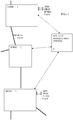
- FIG. 1 shows a schematic view of a number of switching nodes in part of an optical network according to an embodiment.
- Three switching nodes 1, 2 and 3 are shown, with optical paths between the nodes. Other nodes are not shown. Some possible implementations of the nodes are explained below in more detail.
- Each of the switching nodes may be ROADMs or OXCs for example.
- the switching nodes can route communications traffic from one optical path to another, or can add or drop traffic from or to an add drop interface, which may be coupled to a local network for example.
- an upper one and a lower one of the switching nodes is shown with an add drop interface, and a middle switching node is shown without such an interface.
- a routing management system 4 is typically provided, coupled to all the nodes, to control the configuration of switches in the nodes. This may be centralized or at least partly distributed. It can be implemented using conventional communications links of low bandwidth and typically slower than and independent of those used for the communications traffic.
- the routing management system can be implemented as software running on PCs or other conventional processing equipment.
- FIG. 2 shows a schematic view of an ROADM according to conventional practice, for reference, and to show an example of a node to which the embodiments described below can be applied.
- the node has an electrical switch 700 arranged to pass through traffic or to add or drop traffic to an add drop interface in the form of a client interface.
- the switch is coupled to multiple incoming optical paths 1....i.
- Each path can carry a WDM signal which is fed to an optical preamplifier 418 then a wavelength demultiplexer 419. Separated wavelengths are each fed on separate fibers 417 to input converters in the form of optical to electrical converters 420.
- the individual electrical signals are all fed to a framer 710 in the form of circuitry for OTN frame processing including FEC processing for example.
- the signal is then switched by the switch, either to pass through or to be dropped to the client interface.
- Another framer 710 is provided at the output of the switch for processing signals corresponding to all the wavelengths to be output onto output optical paths i+1....M. Clearly there need not be the same number of outputs as inputs.
- the output electrical signals are fed to output converters 425 and then optical signals at individual wavelengths are multiplexed into a WDM optical signal by multiplexer 421.
- An example of a framer circuit available commercially is a CS6001 chip made by Cortina Systems Inc..
- the CS6001 Transport Processor supports Core transport processing for various protocols:
- FIG. 3 shows a schematic view of a sink node 90 according to an embodiment.
- An optical signal is received from another node.
- An optical to electrical converter and analog to digital converter 100 is provided to output a digital signal at a clock rate of the receiver and corresponding to a clock rate of the transmission.
- the digital signal is fed to the framer 110 which finds the framing information and thus is able to distinguish different parts of each frame, including the FEC information.
- FEC processing circuitry 120 is also provided.
- An indication of errors is output and a count of the errors detected by the FEC, or an error rate is monitored by an error rate monitor 130.
- a processor and a program 140 of instructions to be executed by the processor are used to generate a request to adapt the length of FEC information and the clock rate of the transmission, according to the monitored error rate.
- the sink node can then adapt to the new length of FEC in the transmission and to the adapted transmission clock rate. This can be done by the processor instructing the converter and other parts of the node to use a lower clock rate for example.
- the power saving can in some cases be at the transmission node only, if the sink node continues to use a higher clock rate and does not have a low power mode for the FEC part.
- various levels of power saving can also be achieved in the sink node.
- the converter and the framer can operate at a lower clock rate.
- the FEC part can also operate at a lower clock rate, or can be put into a lower power mode such as a standby mode where little or no digital processing is carried out, or a supply voltage is lowered or shut off to some unused parts of the circuitry.
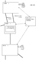
- Figure 4 shows a time chart with time flowing down the drawing.
- the left column has the actions at the source side, and the right column has the actions at the sink side of the link.
- a frame is transmitted with FEC information.
- the frame is received and errors are detected.
- the errors detected can be errors which are corrected by the FEC part. This is usually better than detecting errors remaining after FEC has been processed, as there may not be any remaining.
- the error rate is less than a threshold. If so, then it is assumed that the length of the FEC information can be adapted by reducing the length or disabling the FEC. A request is sent to the transmitter to request such adaptation of the FEC.
- the transmitter receives the request and continues transmitting frames but with the FEC disabled and the transmission clock rate slowed down.
- the error rate can be compared to a number of thresholds to determine if the FEC can be reduced in length rather than completely disabled.
- the sink node continues to receive the frames at the lower clock rate, and continues to monitor an error rate. This can be done by parity checks or other ways without needing the FEC information, once the FEC is disabled.
- the sink node it is determined whether the error rate is greater than a second threshold. If so, it is assumed that more FEC is needed, and the sink node sends a request to the transmitter to enable or increase the length of the FEC information.
- the source node receives the request and continues the transmissions with the FEC enabled and the transmission clock rate speeded up.
- Figure 5 shows another embodiment of a sink node 90. This is similar to the embodiment of figure 3 , and in addition the processor is arranged to send the request to the source node using overhead bytes on a corresponding optical path in the reverse direction to reach the source node. Hence the processor in the sink node is linked to a framer 110 as shown in figure 5 , to cause the framer to add the request into the overhead bytes. The framer feeds a digital signal to a converter 102 which carries out digital to analog conversion and electrical to optical conversion, to transmit frames which include the request.
- Figure 5 also shows the processor able to control the converter to change a clock rate, and to control the FEC part to reduce an amount of processing or to put the FEC part into a low power mode.
- other parts can have their clock rates slowed, including the processor itself, or be put into low power modes, according to the current adaptation of the FEC.
- FIG. 6 shows a schematic view of an embodiment of a source node 92.
- Payload data is fed to a framer 112, which calculates the FEC information and outputs a digital signal including the FEC information to a converter 102 which carries out digital to analog conversion and electrical to optical conversion, to transmit frames to the sink node.
- a request to adapt the FEC and adapt the clock rate of the transmissions can be received by the source node from the sink node. This is received at a processor arranged to execute a program 142.
- This processor is linked to the framer to control a transmission clock speed and to command adapting of the FEC operations of the framer. This can mean for example sending a command specifying a length of the FEC information to be calculated by the framer and included in each frame. This may involve for example sending a FEC disable or enable command to the framer.
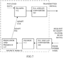
- Figure 7 shows a schematic view of another embodiment of a source node 92, similar to that of figure 6 .
- the request is received and detected in the overhead bytes of a corresponding optical channel in the reverse direction from the sink node.
- the optical signal from the sink node carrying the request is received at a converter 103 which has an optical to electrical converter part and an electrical analog to digital converter, to output a digital signal at a clock rate of the transmission.
- a framer part 112 can distinguish the frames and read the overhead bytes within the frames.
- the request can be fed to the processor and program 142, which can then respond by controlling the framer to adapt the FEC and the transmission clock rate.
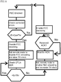
- Figure 8 shows a flow chart according to another embodiment based on G.709 frames and using overhead bytes to send the request.
- the OTUk link is set up both the FEC encoding and decoding are enabled (Starting Point at the top of the drawing).
- the OCh/OTUk-a_A_Sk function decides if the FEC is necessary for that link or not:
- the example is for adapting by enabling or disabling the FEC, it can also be arranged to adapt by increasing or decreasing the length of the FEC information. Having a longer FEC part can enable more errors to be corrected.
- the above protocol messages can optionally be transported via one of the G.709 OTUk OH (overhead) bytes.
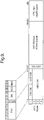
- a frame has four rows, and the OTU overhead is comprised of SM, GCC0 and RES bytes, after the frame alignment bytes FASOH, and starting at row 1 column 8.
- the section monitoring (SM) bytes are used for the trail trace identifier (TTI), parity (BIP-8) and the backward error indicator (BEI), or backward incoming alignment error (BIAE), backward defect indicator (BDI), and incoming alignment error (IAE).
- General communication channel 0 (GCC0) is a clear channel used for transmission of information between OUT termination points.
- the reserved (RES) bytes are currently undefined in the standard. Hence these bytes, located at row 1, column 13 or 14 of the OTUk frame could be used for sending the above mentioned messages for requesting FEC adaptation and clock rate changes.
- Figure 9 also shows the FEC bytes at the end of each row of the frame in the ITU G.709 standard.
- FEC is the last part added to the frame before the frame is scrambled.
- the frame has four rows. Each row is broken down into 16 sub-rows comprised of 255 bytes each.
- a sub-row is composed of interleaved bytes so that the first sub-row contains the first overhead (OH) byte, the first payload byte and the first FEC byte, and so on for the remaining sub-rows of each row in the frame.
- the first FEC byte starts at position 240 for all sub-rows.
- the FEC uses a Reed-Solomon RS (255/239) coding technique. This means that 239 bytes are required to compute a 16-byte parity check.
- the FEC can correct up to eight (bytes) errors per sub-row (codeword) or detect up to 16 byte errors without correcting any.
- the FEC is more resilient to error burst, where up to 128 consecutive bytes can be corrected per OTU frame row.
- other ways of sending the requests for FEC adaptation and thus clock rate changes can also be envisaged, such as from source to sink via the routing management system shown in figure 1 , or some other separate management information path.
- Figures 10 and 11 show an embodiment which uses protection switching to reduce errors which might be caused during a transition of the transmission clock.
- Figure 10 shows a network view similar to that of claim 1, with a protection path between nodes 1 and 2, and a protection controller part 7 at node 2.
- Figure 11 shows a time chart similar to that of figure 4 , but with alterations to provide for use of a protection path during clock rate changes.
- Node 1 can be regarded as a source node and node 2 as a sink node.
- step 24 instead of step 24, there is a step 26 at which the sink node determines if the error rate is less than a threshold, then the protection controller 7 is made to switch to using the protection path instead of the working path. Then a request is made as in step 24, to request the source node to disable the FEC and reduce the transmission clock rate.
- Step 34 is as in figure 4 .
- the sink node requests the protection path controller to switch back to the main path, instead of using the protection path.
- the sink node requests that the protection path also use the slower clock rate. This can involve a similar exchange of messages as set out above. Steps 50 and 64 can be the same as in figure 4 , or can be altered to request the protection path be used while the transmission clock rate changes.
- the embodiments as described can enable the operator have the FEC enabled on a link only when necessary, to tune the transmission clock accordingly and therefore avoid power consumption for the unnecessary FEC processing, and the unnecessarily high transmission clock rate.
- the converter can also be arranged to adapt its clock rate to match the adapted clock rate of the transmission. This can enable further power saving, though in principle the receiver could oversample the transmitted data.
- the sink node can have a transmitter for transmitting frames to the other node, the frames having an overhead part, and the framer being arranged to incorporate the request into the overhead part of a frame. This is likely to be the fastest way of passing messages so that disruptions during adaptations can be minimised.
- the network can have a protection controller for controlling a protection path for the transmissions to the node, the processor being arranged to request the protection controller to use the protection path during the adapting of the clock rate. This can help minimise disruption to payload data transmission, possibly making it hitless, but can be more complex and time consuming.
- the processor can be arranged to detect an acknowledgement from the other node of the request, before enabling the converter to adapt its clock rate. This can help minimise disruption during adaptations.
- the error corrector can have a low power mode, for use when the error correction part is no longer being sent by the other node, which can help further reduce power consumption.
- the monitor can be arranged to monitor at least errors detected by the error corrector when the error correction part is being sent, and to monitor at least a frame parity check by the framer, when the error correction part is not being sent. This makes use of existing mechanisms to minimise additions, and maintain more compatibility with existing standards.
- the source node can have a receiver for receiving frames from the other node, the frames having an overhead part, and the framer being arranged to read the request from the overhead part of a frame. This enables rapid passing of messages so that disruptions during adaptations are minimised.
- the source or sink node can be arranged so that the adaptation of the clock rate corresponds to an increase or decrease in a length of the frame caused by the adaptation of the length of the error correction part. This helps make the most use of dead time, without altering overall frame time, and can help maintain compatibility with standards.
- the frames can be compatible with the definition of OTUk frames described in standard G.709. This is a widely used standard though in principle the techniques can be applicable to other types of frames.
- Additional method steps can involve sending the request from the sink node by encoding the request in an overhead part of a frame and sending that frame from the sink node to the source node.
- Another additional feature is the receiving step comprising digitizing at a receiver clock rate a received optical signal, and adapting the receiver clock rate to match the adapted clock rate of the transmission.
- Another such additional step is sending an acknowledgement from the source node to the sink node after the source node has received the request.
- the sink node can have circuitry for the error correcting, and the method can have the step of putting the circuitry into a low power mode when the error correction part is no longer being sent by the source node.
Claims (16)
- Noeud pour un réseau de communication, le noeud comprenant :un convertisseur (100) pour numériser, à une fréquence d'horloge de récepteur, un signal optique reçu qui est reçu sur une liaison optique en provenance d'un émetteur optique à un autre noeud,un trameur (110) pour détecter des trames dans les données numériques, chacune des trames comportant une partie de charge utile, etune partie de correction d'erreur sans voie de retour, le noeud comprenant également :un correcteur d'erreur (120) pour corriger des erreurs dans la partie de charge utile en utilisant la partie de correction d'erreur sans voie de retour de la trame,un moniteur (130) pour surveiller un taux d'erreur dans la partie de charge utile reçue, etun processeur (140) agencé pour envoyer, lorsqu'il est déterminé que le taux d'erreur surveillé est inférieur à un seuil, une demande à l'émetteur optique pour réduire une longueur de la partie de correction d'erreur sans voie de retour transmise et pour réduire une fréquence d'horloge de la transmission des trames d'une quantité pour maintenir un débit de transmission identique des parties de charge utile.
- Noeud selon la revendication 1, dans lequel le convertisseur (100) est également agencé pour adapter sa fréquence d'horloge afin qu'elle corresponde à la fréquence d'horloge adaptée de la transmission.
- Noeud selon la revendication 1 ou 2, comprenant en outre un émetteur pour transmettre des trames à l'autre noeud, les trames comportant une partie de surdébit, et le trameur (110) étant agencé pour incorporer la demande dans la partie de surdébit d'une trame.
- Noeud selon l'une quelconque des revendications précédentes, dans lequel le réseau comprend un organe de commande de protection (4) pour commander une voie de protection pour les transmissions au noeud, le processeur (140) étant agencé pour demander à l'organe de commande de protection (4) d'utiliser la voie de protection pendant l'adaptation de la fréquence d'horloge.
- Noeud selon l'une quelconque des revendications précédentes, dans lequel le processeur (140) est agencé pour détecter un accusé de réception, de l'autre noeud, de la demande, avant de permettre au convertisseur (100) d'adapter sa fréquence d'horloge.
- Noeud selon l'une quelconque des revendications précédentes, dans lequel le correcteur d'erreur (120) comprend un mode de basse puissance à utiliser lorsque la partie de correction d'erreur n'est plus envoyée par l'autre noeud.
- Noeud selon l'une quelconque des revendications précédentes, dans lequel le moniteur (130) est agencé pour surveiller au moins des erreurs détectées par le correcteur d'erreur (120) lorsque la partie de correction d'erreur est envoyée, et pour surveiller au moins un contrôle de parité de trame par le trameur (110) lorsque la partie de correction d'erreur n'est pas envoyée.
- Noeud pour un réseau de communication, le noeud comprenant :un émetteur optique pour transmettre un signal optique sur une liaison optique à un autre noeud, le noeud comprenant également :un trameur (112) pour délivrer des trames comportant une partie de charge utile et une partie de correction d'erreur à une première fréquence d'horloge,un convertisseur (102) pour convertir les trames dans le signal optique pour une transmission,un processeur (142) agencé pour recevoir une demande envoyée depuis un noeud de réception, dans lequel il est déterminé qu'un taux d'erreur surveillé est inférieur à un seuil, pour réduire la taille de la partie de correction d'erreur sans voie de retour transmise et, en réponse, pour réduire une longueur de la partie de correction d'erreur dans les trames, et réduire une fréquence d'horloge du trameur (112) d'une quantité pour maintenir un débit de transmission identique des parties de charge utile.
- Noeud selon la revendication 8, comprenant un récepteur pour recevoir des trames depuis l'autre noeud, les trames comprenant une partie de surdébit, et le trameur (112) étant agencé pour lire la demande d'adaptation de la taille de la partie de correction d'erreur sans voie de retour depuis la partie de surdébit d'une trame.
- Noeud selon l'une quelconque des revendications précédentes, dans lequel l'adaptation de la fréquence d'horloge correspond à une augmentation ou une réduction d'une longueur de la trame provoquée par l'adaptation de la longueur de la partie de correction d'erreur.
- Noeud selon l'une quelconque des revendications précédentes, dans lequel les trames sont compatibles avec la définition de trames OTUk selon la norme G.709.
- Procédé de transmission d'une charge utile de données depuis un premier noeud d'un réseau de communication agissant en tant que noeud source à un deuxième noeud agissant en tant que noeud cible, le procédé comprenant les étapes de :la transmission de trames de données depuis le noeud source, chacune des trames comportant une partie de charge utile et une partie de correction d'erreur sans voie de retour,la réception, au noeud source, d'une demande provenant du noeud cible pour réduire une longueur de la partie de correction d'erreur sans voie de retour transmise en fonction d'un taux d'erreur surveillé déterminé comme étant inférieur à un seuil et pour réduire une fréquence d'horloge de la transmission de la trame, en fonction de la longueur adaptée de la partie de correction d'erreur sans voie de retour d'une quantité pour maintenir un débit de transmission identique des parties de charge utile, etau noeud source, la réduction de la longueur de la partie de correction d'erreur sans voie de retour dans chaque trame.
- Procédé de réception d'une charge utile de données envoyée depuis un premier noeud d'un réseau de communication agissant en tant que noeud source à un deuxième noeud agissant en tant que noeud cible, le procédé comprenant les étapes de :au noeud cible, la réception de trames de données depuis le noeud source, chacune des trames comportant une partie de charge utile et une partie de correction d'erreur sans voie de retour,la correction d'erreurs dans la partie de charge utile en utilisant la partie de correction d'erreur sans voie de retour de la trame,la surveillance d'un taux d'erreur dans la partie de charge utile reçue, etl'envoi d'une demande au noeud source, s'il est déterminé que le taux d'erreur surveillé est inférieur à un seuil, pour réduire une longueur de la partie de correction d'erreur sans voie de retour transmise en fonction du taux d'erreur surveillé et pour réduire une fréquence d'horloge de la transmission de la trame, en fonction de la quantité adaptée de la partie de correction d'erreur sans voie de retour d'une quantité pour maintenir un débit de transmission identique des parties de charge utile, etla poursuite de la réception, au noeud cible, des données à la fréquence d'horloge adaptée de l'émetteur et avec une longueur réduite de la partie de correction d'erreur sans voie de retour dans chaque trame.
- Procédé de transmission d'une charge utile de données depuis un premier noeud d'un réseau de communication agissant en tant que noeud source à un deuxième noeud agissant en tant que noeud cible, le procédé comprenant les étapes de :la transmission de trames de données depuis le noeud source, chacune des trames comportant une partie de charge utile et une partie de correction d'erreur sans voie de retour,au noeud cible, la réception des données, la correction d'erreurs dans la partie de charge utile en utilisant la partie de correction d'erreur sans voie de retour de la trame, la surveillance d'un taux d'erreur dans la partie de charge utile reçue, et l'envoi d'une demande au noeud source pour réduire une longueur de la partie de correction d'erreur sans voie de retour transmise lorsqu'il est déterminé que le taux d'erreur surveillé est inférieur à un seuil et pour réduire une fréquence d'horloge de la transmission de la trame, en fonction de la quantité réduite de la partie de correction d'erreur sans voie de retour d'une quantité pour maintenir un débit de transmission identique des parties de charge utile,au noeud source, la réduction de la longueur de la partie de correction d'erreur sans voie de retour dans chaque trame, etau noeud cible, la poursuite de la réception des trames de données ayant la longueur réduite de la partie de correction d'erreur sans voie de retour dans chaque trame.
- Support de mémorisation lisible par ordinateur comprenant un programme mémorisé à exécuter par un processeur (140) pour commander un noeud pour un réseau de communication, le noeud comprenant un convertisseur (100) pour numériser, à une fréquence d'horloge de récepteur, un signal optique reçu qui est reçu sur une liaison optique en provenance d'un émetteur optique à un autre noeud, un trameur (110) pour détecter des trames dans les données numériques, chacune des trames ayant une partie de charge utile, et une partie de correction d'erreur sans voie de retour, le noeud comprenant également un correcteur d'erreur (120) pour corriger des erreurs dans la partie de charge utile en utilisant la partie de correction d'erreur sans voie de retour de la trame, et un moniteur (130) pour surveiller un taux d'erreur dans la partie de charge utile reçue,
le programme comprenant des instructions qui, lorsqu'elles sont exécutées par le processeur (140), amènent le processeur à effectuer les étapes de :la réception d'un taux d'erreur surveillé en provenance du moniteur (130),l'envoi, s'il est déterminé que le taux d'erreur surveillé est inférieur à un seuil, d'une demande à l'émetteur pour réduire une longueur de la partie de correction d'erreur sans voie de retour transmise et pour réduire une fréquence d'horloge de la transmission de la trame d'une quantité pour maintenir un débit de transmission identique des parties de charge utile. - Support de mémorisation lisible par ordinateur comprenant un programme mémorisé à exécuter par un processeur pour commander un noeud pour un réseau de communication, le noeud comprenant :un émetteur optique pour transmettre un signal optique sur une liaison optique à un autre noeud, le noeud comprenant également :un trameur (112) pour délivrer des trames comportant une partie de charge utile et une partie de correction d'erreur à une première fréquence d'horloge,un convertisseur (102) pour convertir les trames dans le signal optique pour une transmission, etun processeur (142) agencé pour recevoir une demande, envoyée depuis un noeud de réception dans lequel il est déterminé qu'un taux d'erreur surveillé est inférieur à un seuil, pour réduire la taille de la partie de correction d'erreur sans voie de retour transmise et, en réponse, pour réduire une longueur de la partie de correction d'erreur dans les trames, et réduire une fréquence d'horloge du trameur (112), le programme comprenant des instructions qui, lorsqu'elles sont exécutées par le processeur (142), amènent le processeur (142) à effectuer les étapes suivantes :amener l'émetteur optique à transmettre des trames de données, chaque trame comportant une partie de charge utile et une partie de correction d'erreur sans voie de retour,recevoir une demande provenant du noeud cible pour réduire une longueur de la partie de correction d'erreur sans voie de retour transmise lorsqu'il est déterminé qu'un taux d'erreur surveillé est inférieur à un seuil, etamener l'émetteur optique à réduire une fréquence d'horloge de la transmission de la trame en fonction de la longueur réduite de la partie de correction d'erreur sans voie de retour d'une quantité pour maintenir un débit de transmission identique des parties de charge utile, etau noeud source, réduire la longueur de la partie de correction d'erreur sans voie de retour dans chaque trame.
Priority Applications (1)
| Application Number | Priority Date | Filing Date | Title |
|---|---|---|---|
| EP11708257.8A EP2656526B1 (fr) | 2010-12-23 | 2011-03-15 | Réseau de communication utilisant une correction d'erreurs sans voie de retour (fec) adaptable |
Applications Claiming Priority (3)
| Application Number | Priority Date | Filing Date | Title |
|---|---|---|---|
| EP10196749 | 2010-12-23 | ||
| PCT/EP2011/053847 WO2012084270A1 (fr) | 2010-12-23 | 2011-03-15 | Réseau de communication utilisant une correction d'erreurs sans voie de retour (fec) adaptable |
| EP11708257.8A EP2656526B1 (fr) | 2010-12-23 | 2011-03-15 | Réseau de communication utilisant une correction d'erreurs sans voie de retour (fec) adaptable |
Publications (2)
| Publication Number | Publication Date |
|---|---|
| EP2656526A1 EP2656526A1 (fr) | 2013-10-30 |
| EP2656526B1 true EP2656526B1 (fr) | 2018-06-13 |
Family
ID=44625389
Family Applications (1)
| Application Number | Title | Priority Date | Filing Date |
|---|---|---|---|
| EP11708257.8A Not-in-force EP2656526B1 (fr) | 2010-12-23 | 2011-03-15 | Réseau de communication utilisant une correction d'erreurs sans voie de retour (fec) adaptable |
Country Status (3)
| Country | Link |
|---|---|
| US (2) | US9264168B2 (fr) |
| EP (1) | EP2656526B1 (fr) |
| WO (1) | WO2012084270A1 (fr) |
Families Citing this family (12)
| Publication number | Priority date | Publication date | Assignee | Title |
|---|---|---|---|---|
| WO2012084270A1 (fr) * | 2010-12-23 | 2012-06-28 | Telefonaktiebolaget L M Ericsson (Publ) | Réseau de communication utilisant une correction d'erreurs sans voie de retour (fec) adaptable |
| JP5426604B2 (ja) * | 2011-04-26 | 2014-02-26 | 富士通テレコムネットワークス株式会社 | 光パケット交換システム |
| US9231721B1 (en) * | 2012-06-28 | 2016-01-05 | Applied Micro Circuits Corporation | System and method for scaling total client capacity with a standard-compliant optical transport network (OTN) |
| US8983294B2 (en) * | 2012-06-29 | 2015-03-17 | Alcatel Lucent | Forward error correction for an optical transport system |
| US9166628B2 (en) | 2013-12-13 | 2015-10-20 | Alcatel Lucent | Use of parity-check coding for carrier-phase estimation in an optical transport system |
| US9414135B2 (en) * | 2013-12-24 | 2016-08-09 | Nec Corporation | Flexible-client, flexible-line interface transponder |
| EP2961092A1 (fr) * | 2014-06-27 | 2015-12-30 | Orange | Procédé de communication de données multimédia entre deux dispositifs incorporant des stratégies efficaces de correction d'erreur, le programme d'ordinateur associé, le module de qualité de communication et l'appareil |
| US9692503B2 (en) * | 2014-11-04 | 2017-06-27 | Verizon Patent And Licensing Inc. | Network protection through excess directions of reconfigurable optical add/drop multiplexor (ROADM) |
| EP3086497B1 (fr) * | 2015-04-24 | 2019-03-06 | Alcatel Lucent | Appareil et procédé pour un noeud de réseau régénératif entre une première et une seconde partie de liaison |
| US10263764B2 (en) * | 2016-05-03 | 2019-04-16 | The Boeing Company | Auto-adaptive digital clock system and method for optimizing data communications |
| EP3672121A1 (fr) * | 2018-12-21 | 2020-06-24 | Xieon Networks S.à r.l. | Reconfiguration de paramètres de codage de messages dans un réseau optique |
| US11764902B2 (en) * | 2020-10-15 | 2023-09-19 | Nokia Solutions And Networks Oy | Forward error correction control |
Family Cites Families (15)
| Publication number | Priority date | Publication date | Assignee | Title |
|---|---|---|---|---|
| US5699365A (en) * | 1996-03-27 | 1997-12-16 | Motorola, Inc. | Apparatus and method for adaptive forward error correction in data communications |
| US6683855B1 (en) * | 1998-08-31 | 2004-01-27 | Lucent Technologies Inc. | Forward error correction for high speed optical transmission systems |
| US20060274840A1 (en) * | 2005-06-06 | 2006-12-07 | Marcos Tzannes | Method for seamlessly changing power modes in an ADSL system |
| US6802033B1 (en) * | 1999-04-06 | 2004-10-05 | International Business Machines Corporation | Low-power critical error rate communications controller |
| JP4105723B2 (ja) * | 2003-08-05 | 2008-06-25 | 富士通株式会社 | 再生中継方法及びその装置 |
| US7162676B2 (en) * | 2003-09-22 | 2007-01-09 | Adtran, Inc. | Data communication system and method for selectively implementing forward error correction |
| JP4573663B2 (ja) * | 2005-02-16 | 2010-11-04 | 富士通株式会社 | データ中継装置、データ中継方法、データ送受信装置およびデータ通信システム |
| WO2007024317A2 (fr) * | 2005-06-06 | 2007-03-01 | New World Tmt Limited | Qualite de service dans un reseau optique |
| US7634194B2 (en) * | 2006-06-05 | 2009-12-15 | Ciena Corporation | Multi-channel protection switching systems and methods for increased reliability and reduced cost |
| US7885342B2 (en) * | 2007-03-05 | 2011-02-08 | Cisco Technology, Inc. | Managing bit error rates on point-to-point wireless links in a network |
| US8315574B2 (en) * | 2007-04-13 | 2012-11-20 | Broadcom Corporation | Management of variable-rate communication links |
| EP2314005B1 (fr) | 2008-04-29 | 2017-11-29 | Thomson Licensing | Procédé et système pour adapter une correction d'erreurs sans voie de retour dans une diffusion groupée sur des réseaux sans fil |
| JP2010028629A (ja) * | 2008-07-23 | 2010-02-04 | Nec Corp | 局側終端装置、加入者側終端装置、光通信システム、通信方法、装置のプログラム |
| US8707137B2 (en) * | 2009-09-14 | 2014-04-22 | Celtro Ltd. Company | Adapting bit error rate to a target quality of service |
| WO2012084270A1 (fr) * | 2010-12-23 | 2012-06-28 | Telefonaktiebolaget L M Ericsson (Publ) | Réseau de communication utilisant une correction d'erreurs sans voie de retour (fec) adaptable |
-
2011
- 2011-03-15 WO PCT/EP2011/053847 patent/WO2012084270A1/fr active Application Filing
- 2011-03-15 EP EP11708257.8A patent/EP2656526B1/fr not_active Not-in-force
- 2011-03-15 US US13/996,444 patent/US9264168B2/en not_active Expired - Fee Related
-
2015
- 2015-12-28 US US14/981,743 patent/US9537607B2/en active Active
Non-Patent Citations (1)
| Title |
|---|
| None * |
Also Published As
| Publication number | Publication date |
|---|---|
| WO2012084270A1 (fr) | 2012-06-28 |
| US9537607B2 (en) | 2017-01-03 |
| EP2656526A1 (fr) | 2013-10-30 |
| US9264168B2 (en) | 2016-02-16 |
| US20130343750A1 (en) | 2013-12-26 |
| US20160119082A1 (en) | 2016-04-28 |
Similar Documents
| Publication | Publication Date | Title |
|---|---|---|
| US9537607B2 (en) | Communications network using adaptable FEC | |
| EP2745476B1 (fr) | Redimensionnement du flux de trafic existant dans un réseau de transport optique | |
| US10462028B2 (en) | Efficient ethernet signal transport and scheduling | |
| CN1748381B (zh) | 用于可变长度分组的高效成帧方法 | |
| US10257596B2 (en) | Systems and methods for managing excess optical capacity and margin in optical networks | |
| US10164728B2 (en) | Method and apparatus for generic mapping procedure GMP and method and apparatus for generic mapping procedure GMP demapping | |
| JP4511557B2 (ja) | 光通信のための方法、装置及びシステム | |
| US8693864B2 (en) | Optical network system, optical redundant switching apparatus, and WDM apparatus | |
| US8934479B2 (en) | Super optical channel transport unit signal supported by multiple wavelengths | |
| US9231721B1 (en) | System and method for scaling total client capacity with a standard-compliant optical transport network (OTN) | |
| US11438069B2 (en) | Data transmission method and apparatus | |
| US20150229404A1 (en) | Hitless modulation scheme change systems and methods in optical networks | |
| JP4402650B2 (ja) | 光伝送システム、光送信器および光受信器 | |
| EP2790343B1 (fr) | Procédé de génération de trame, dispositif d'émission optique et système d'émission optique | |
| JP5266546B2 (ja) | デジタル伝送システム | |
| US11223422B2 (en) | Method and apparatus for processing ethernet data in optical network, and system | |
| US9755756B2 (en) | Transmission device, transmission system, and transmission method | |
| US20030039207A1 (en) | Transmission apparatus equipped with an alarm transfer device | |
| US6594047B1 (en) | Apparatus and method for providing optical channel overhead in optical transport networks | |
| US8934769B2 (en) | Optical transport network alarms | |
| US20120281983A1 (en) | Method and apparatus for generating resize control overhead in optical transport network | |
| KR100500665B1 (ko) | 기가비트 이더넷 신호 다중화 장치 및 그를 이용한 광트랜스폰더 |
Legal Events
| Date | Code | Title | Description |
|---|---|---|---|
| PUAI | Public reference made under article 153(3) epc to a published international application that has entered the european phase |
Free format text: ORIGINAL CODE: 0009012 |
|
| 17P | Request for examination filed |
Effective date: 20130521 |
|
| AK | Designated contracting states |
Kind code of ref document: A1 Designated state(s): AL AT BE BG CH CY CZ DE DK EE ES FI FR GB GR HR HU IE IS IT LI LT LU LV MC MK MT NL NO PL PT RO RS SE SI SK SM TR |
|
| DAX | Request for extension of the european patent (deleted) | ||
| STAA | Information on the status of an ep patent application or granted ep patent |
Free format text: STATUS: EXAMINATION IS IN PROGRESS |
|
| 17Q | First examination report despatched |
Effective date: 20161221 |
|
| REG | Reference to a national code |
Ref country code: DE Ref legal event code: R079 Ref document number: 602011049207 Country of ref document: DE Free format text: PREVIOUS MAIN CLASS: H04J0014000000 Ipc: H04J0014020000 |
|
| RIC1 | Information provided on ipc code assigned before grant |
Ipc: H04L 1/20 20060101ALI20171127BHEP Ipc: H04L 1/00 20060101ALI20171127BHEP Ipc: H04J 14/02 20060101AFI20171127BHEP Ipc: H04B 10/079 20130101ALI20171127BHEP |
|
| GRAP | Despatch of communication of intention to grant a patent |
Free format text: ORIGINAL CODE: EPIDOSNIGR1 |
|
| STAA | Information on the status of an ep patent application or granted ep patent |
Free format text: STATUS: GRANT OF PATENT IS INTENDED |
|
| INTG | Intention to grant announced |
Effective date: 20180105 |
|
| GRAS | Grant fee paid |
Free format text: ORIGINAL CODE: EPIDOSNIGR3 |
|
| GRAA | (expected) grant |
Free format text: ORIGINAL CODE: 0009210 |
|
| STAA | Information on the status of an ep patent application or granted ep patent |
Free format text: STATUS: THE PATENT HAS BEEN GRANTED |
|
| AK | Designated contracting states |
Kind code of ref document: B1 Designated state(s): AL AT BE BG CH CY CZ DE DK EE ES FI FR GB GR HR HU IE IS IT LI LT LU LV MC MK MT NL NO PL PT RO RS SE SI SK SM TR |
|
| REG | Reference to a national code |
Ref country code: GB Ref legal event code: FG4D |
|
| REG | Reference to a national code |
Ref country code: CH Ref legal event code: EP Ref country code: AT Ref legal event code: REF Ref document number: 1009585 Country of ref document: AT Kind code of ref document: T Effective date: 20180615 |
|
| REG | Reference to a national code |
Ref country code: DE Ref legal event code: R096 Ref document number: 602011049207 Country of ref document: DE |
|
| REG | Reference to a national code |
Ref country code: IE Ref legal event code: FG4D |
|
| REG | Reference to a national code |
Ref country code: NL Ref legal event code: MP Effective date: 20180613 |
|
| REG | Reference to a national code |
Ref country code: LT Ref legal event code: MG4D |
|
| PG25 | Lapsed in a contracting state [announced via postgrant information from national office to epo] |
Ref country code: ES Free format text: LAPSE BECAUSE OF FAILURE TO SUBMIT A TRANSLATION OF THE DESCRIPTION OR TO PAY THE FEE WITHIN THE PRESCRIBED TIME-LIMIT Effective date: 20180613 Ref country code: CY Free format text: LAPSE BECAUSE OF FAILURE TO SUBMIT A TRANSLATION OF THE DESCRIPTION OR TO PAY THE FEE WITHIN THE PRESCRIBED TIME-LIMIT Effective date: 20180613 Ref country code: LT Free format text: LAPSE BECAUSE OF FAILURE TO SUBMIT A TRANSLATION OF THE DESCRIPTION OR TO PAY THE FEE WITHIN THE PRESCRIBED TIME-LIMIT Effective date: 20180613 Ref country code: FI Free format text: LAPSE BECAUSE OF FAILURE TO SUBMIT A TRANSLATION OF THE DESCRIPTION OR TO PAY THE FEE WITHIN THE PRESCRIBED TIME-LIMIT Effective date: 20180613 Ref country code: NO Free format text: LAPSE BECAUSE OF FAILURE TO SUBMIT A TRANSLATION OF THE DESCRIPTION OR TO PAY THE FEE WITHIN THE PRESCRIBED TIME-LIMIT Effective date: 20180913 Ref country code: SE Free format text: LAPSE BECAUSE OF FAILURE TO SUBMIT A TRANSLATION OF THE DESCRIPTION OR TO PAY THE FEE WITHIN THE PRESCRIBED TIME-LIMIT Effective date: 20180613 Ref country code: BG Free format text: LAPSE BECAUSE OF FAILURE TO SUBMIT A TRANSLATION OF THE DESCRIPTION OR TO PAY THE FEE WITHIN THE PRESCRIBED TIME-LIMIT Effective date: 20180913 |
|
| PG25 | Lapsed in a contracting state [announced via postgrant information from national office to epo] |
Ref country code: GR Free format text: LAPSE BECAUSE OF FAILURE TO SUBMIT A TRANSLATION OF THE DESCRIPTION OR TO PAY THE FEE WITHIN THE PRESCRIBED TIME-LIMIT Effective date: 20180914 Ref country code: RS Free format text: LAPSE BECAUSE OF FAILURE TO SUBMIT A TRANSLATION OF THE DESCRIPTION OR TO PAY THE FEE WITHIN THE PRESCRIBED TIME-LIMIT Effective date: 20180613 Ref country code: LV Free format text: LAPSE BECAUSE OF FAILURE TO SUBMIT A TRANSLATION OF THE DESCRIPTION OR TO PAY THE FEE WITHIN THE PRESCRIBED TIME-LIMIT Effective date: 20180613 Ref country code: HR Free format text: LAPSE BECAUSE OF FAILURE TO SUBMIT A TRANSLATION OF THE DESCRIPTION OR TO PAY THE FEE WITHIN THE PRESCRIBED TIME-LIMIT Effective date: 20180613 |
|
| REG | Reference to a national code |
Ref country code: AT Ref legal event code: MK05 Ref document number: 1009585 Country of ref document: AT Kind code of ref document: T Effective date: 20180613 |
|
| PG25 | Lapsed in a contracting state [announced via postgrant information from national office to epo] |
Ref country code: NL Free format text: LAPSE BECAUSE OF FAILURE TO SUBMIT A TRANSLATION OF THE DESCRIPTION OR TO PAY THE FEE WITHIN THE PRESCRIBED TIME-LIMIT Effective date: 20180613 |
|
| PG25 | Lapsed in a contracting state [announced via postgrant information from national office to epo] |
Ref country code: RO Free format text: LAPSE BECAUSE OF FAILURE TO SUBMIT A TRANSLATION OF THE DESCRIPTION OR TO PAY THE FEE WITHIN THE PRESCRIBED TIME-LIMIT Effective date: 20180613 Ref country code: SK Free format text: LAPSE BECAUSE OF FAILURE TO SUBMIT A TRANSLATION OF THE DESCRIPTION OR TO PAY THE FEE WITHIN THE PRESCRIBED TIME-LIMIT Effective date: 20180613 Ref country code: IS Free format text: LAPSE BECAUSE OF FAILURE TO SUBMIT A TRANSLATION OF THE DESCRIPTION OR TO PAY THE FEE WITHIN THE PRESCRIBED TIME-LIMIT Effective date: 20181013 Ref country code: PL Free format text: LAPSE BECAUSE OF FAILURE TO SUBMIT A TRANSLATION OF THE DESCRIPTION OR TO PAY THE FEE WITHIN THE PRESCRIBED TIME-LIMIT Effective date: 20180613 Ref country code: AT Free format text: LAPSE BECAUSE OF FAILURE TO SUBMIT A TRANSLATION OF THE DESCRIPTION OR TO PAY THE FEE WITHIN THE PRESCRIBED TIME-LIMIT Effective date: 20180613 Ref country code: EE Free format text: LAPSE BECAUSE OF FAILURE TO SUBMIT A TRANSLATION OF THE DESCRIPTION OR TO PAY THE FEE WITHIN THE PRESCRIBED TIME-LIMIT Effective date: 20180613 Ref country code: CZ Free format text: LAPSE BECAUSE OF FAILURE TO SUBMIT A TRANSLATION OF THE DESCRIPTION OR TO PAY THE FEE WITHIN THE PRESCRIBED TIME-LIMIT Effective date: 20180613 |
|
| PG25 | Lapsed in a contracting state [announced via postgrant information from national office to epo] |
Ref country code: IT Free format text: LAPSE BECAUSE OF FAILURE TO SUBMIT A TRANSLATION OF THE DESCRIPTION OR TO PAY THE FEE WITHIN THE PRESCRIBED TIME-LIMIT Effective date: 20180613 Ref country code: SM Free format text: LAPSE BECAUSE OF FAILURE TO SUBMIT A TRANSLATION OF THE DESCRIPTION OR TO PAY THE FEE WITHIN THE PRESCRIBED TIME-LIMIT Effective date: 20180613 |
|
| REG | Reference to a national code |
Ref country code: DE Ref legal event code: R097 Ref document number: 602011049207 Country of ref document: DE |
|
| PLBE | No opposition filed within time limit |
Free format text: ORIGINAL CODE: 0009261 |
|
| STAA | Information on the status of an ep patent application or granted ep patent |
Free format text: STATUS: NO OPPOSITION FILED WITHIN TIME LIMIT |
|
| PGFP | Annual fee paid to national office [announced via postgrant information from national office to epo] |
Ref country code: FR Payment date: 20190325 Year of fee payment: 9 |
|
| 26N | No opposition filed |
Effective date: 20190314 |
|
| PG25 | Lapsed in a contracting state [announced via postgrant information from national office to epo] |
Ref country code: DK Free format text: LAPSE BECAUSE OF FAILURE TO SUBMIT A TRANSLATION OF THE DESCRIPTION OR TO PAY THE FEE WITHIN THE PRESCRIBED TIME-LIMIT Effective date: 20180613 Ref country code: SI Free format text: LAPSE BECAUSE OF FAILURE TO SUBMIT A TRANSLATION OF THE DESCRIPTION OR TO PAY THE FEE WITHIN THE PRESCRIBED TIME-LIMIT Effective date: 20180613 |
|
| PG25 | Lapsed in a contracting state [announced via postgrant information from national office to epo] |
Ref country code: MC Free format text: LAPSE BECAUSE OF FAILURE TO SUBMIT A TRANSLATION OF THE DESCRIPTION OR TO PAY THE FEE WITHIN THE PRESCRIBED TIME-LIMIT Effective date: 20180613 |
|
| REG | Reference to a national code |
Ref country code: CH Ref legal event code: PL |
|
| PG25 | Lapsed in a contracting state [announced via postgrant information from national office to epo] |
Ref country code: AL Free format text: LAPSE BECAUSE OF FAILURE TO SUBMIT A TRANSLATION OF THE DESCRIPTION OR TO PAY THE FEE WITHIN THE PRESCRIBED TIME-LIMIT Effective date: 20180613 Ref country code: LU Free format text: LAPSE BECAUSE OF NON-PAYMENT OF DUE FEES Effective date: 20190315 |
|
| REG | Reference to a national code |
Ref country code: BE Ref legal event code: MM Effective date: 20190331 |
|
| PG25 | Lapsed in a contracting state [announced via postgrant information from national office to epo] |
Ref country code: IE Free format text: LAPSE BECAUSE OF NON-PAYMENT OF DUE FEES Effective date: 20190315 Ref country code: LI Free format text: LAPSE BECAUSE OF NON-PAYMENT OF DUE FEES Effective date: 20190331 Ref country code: CH Free format text: LAPSE BECAUSE OF NON-PAYMENT OF DUE FEES Effective date: 20190331 |
|
| PG25 | Lapsed in a contracting state [announced via postgrant information from national office to epo] |
Ref country code: BE Free format text: LAPSE BECAUSE OF NON-PAYMENT OF DUE FEES Effective date: 20190331 |
|
| PG25 | Lapsed in a contracting state [announced via postgrant information from national office to epo] |
Ref country code: TR Free format text: LAPSE BECAUSE OF FAILURE TO SUBMIT A TRANSLATION OF THE DESCRIPTION OR TO PAY THE FEE WITHIN THE PRESCRIBED TIME-LIMIT Effective date: 20180613 |
|
| PG25 | Lapsed in a contracting state [announced via postgrant information from national office to epo] |
Ref country code: PT Free format text: LAPSE BECAUSE OF FAILURE TO SUBMIT A TRANSLATION OF THE DESCRIPTION OR TO PAY THE FEE WITHIN THE PRESCRIBED TIME-LIMIT Effective date: 20181015 Ref country code: MT Free format text: LAPSE BECAUSE OF NON-PAYMENT OF DUE FEES Effective date: 20190315 |
|
| PG25 | Lapsed in a contracting state [announced via postgrant information from national office to epo] |
Ref country code: FR Free format text: LAPSE BECAUSE OF NON-PAYMENT OF DUE FEES Effective date: 20200331 |
|
| PGFP | Annual fee paid to national office [announced via postgrant information from national office to epo] |
Ref country code: DE Payment date: 20210329 Year of fee payment: 11 |
|
| PG25 | Lapsed in a contracting state [announced via postgrant information from national office to epo] |
Ref country code: HU Free format text: LAPSE BECAUSE OF FAILURE TO SUBMIT A TRANSLATION OF THE DESCRIPTION OR TO PAY THE FEE WITHIN THE PRESCRIBED TIME-LIMIT; INVALID AB INITIO Effective date: 20110315 |
|
| PGFP | Annual fee paid to national office [announced via postgrant information from national office to epo] |
Ref country code: GB Payment date: 20220328 Year of fee payment: 12 |
|
| PG25 | Lapsed in a contracting state [announced via postgrant information from national office to epo] |
Ref country code: MK Free format text: LAPSE BECAUSE OF FAILURE TO SUBMIT A TRANSLATION OF THE DESCRIPTION OR TO PAY THE FEE WITHIN THE PRESCRIBED TIME-LIMIT Effective date: 20180613 |
|
| REG | Reference to a national code |
Ref country code: DE Ref legal event code: R119 Ref document number: 602011049207 Country of ref document: DE |
|
| PG25 | Lapsed in a contracting state [announced via postgrant information from national office to epo] |
Ref country code: DE Free format text: LAPSE BECAUSE OF NON-PAYMENT OF DUE FEES Effective date: 20221001 |
|
| GBPC | Gb: european patent ceased through non-payment of renewal fee |
Effective date: 20230315 |
|
| PG25 | Lapsed in a contracting state [announced via postgrant information from national office to epo] |
Ref country code: GB Free format text: LAPSE BECAUSE OF NON-PAYMENT OF DUE FEES Effective date: 20230315 |
|
| PG25 | Lapsed in a contracting state [announced via postgrant information from national office to epo] |
Ref country code: GB Free format text: LAPSE BECAUSE OF NON-PAYMENT OF DUE FEES Effective date: 20230315 |