EP2656355B1 - Neutronengenerator mit keramischen dickschicht-widerstandsisolatoren für versiegelte hochspannungsröhrenelektroden - Google Patents
Neutronengenerator mit keramischen dickschicht-widerstandsisolatoren für versiegelte hochspannungsröhrenelektroden Download PDFInfo
- Publication number
- EP2656355B1 EP2656355B1 EP11837079.0A EP11837079A EP2656355B1 EP 2656355 B1 EP2656355 B1 EP 2656355B1 EP 11837079 A EP11837079 A EP 11837079A EP 2656355 B1 EP2656355 B1 EP 2656355B1
- Authority
- EP
- European Patent Office
- Prior art keywords
- washer
- thick film
- assembly according
- annular
- target
- Prior art date
- Legal status (The legal status is an assumption and is not a legal conclusion. Google has not performed a legal analysis and makes no representation as to the accuracy of the status listed.)
- Not-in-force
Links
Images


Classifications
-
- H—ELECTRICITY
- H01—ELECTRIC ELEMENTS
- H01J—ELECTRIC DISCHARGE TUBES OR DISCHARGE LAMPS
- H01J29/00—Details of cathode-ray tubes or of electron-beam tubes of the types covered by group H01J31/00
- H01J29/02—Electrodes; Screens; Mounting, supporting, spacing or insulating thereof
-
- H—ELECTRICITY
- H01—ELECTRIC ELEMENTS
- H01J—ELECTRIC DISCHARGE TUBES OR DISCHARGE LAMPS
- H01J3/00—Details of electron-optical or ion-optical arrangements common to two or more basic types of discharge tubes or lamps
- H01J3/02—Electron guns
- H01J3/027—Construction of the gun or parts thereof
-
- H—ELECTRICITY
- H01—ELECTRIC ELEMENTS
- H01J—ELECTRIC DISCHARGE TUBES OR DISCHARGE LAMPS
- H01J29/00—Details of cathode-ray tubes or of electron-beam tubes of the types covered by group H01J31/00
- H01J29/46—Arrangements of electrodes and associated parts for generating or controlling the ray or beam, e.g. electron-optical arrangement
- H01J29/48—Electron guns
- H01J29/485—Construction of the gun or of parts thereof
-
- H—ELECTRICITY
- H01—ELECTRIC ELEMENTS
- H01J—ELECTRIC DISCHARGE TUBES OR DISCHARGE LAMPS
- H01J29/00—Details of cathode-ray tubes or of electron-beam tubes of the types covered by group H01J31/00
- H01J29/96—One or more circuit elements structurally associated with the tube
-
- H—ELECTRICITY
- H01—ELECTRIC ELEMENTS
- H01J—ELECTRIC DISCHARGE TUBES OR DISCHARGE LAMPS
- H01J31/00—Cathode ray tubes; Electron beam tubes
- H01J31/08—Cathode ray tubes; Electron beam tubes having a screen on or from which an image or pattern is formed, picked up, converted, or stored
- H01J31/50—Image-conversion or image-amplification tubes, i.e. having optical, X-ray, or analogous input, and optical output
-
- H—ELECTRICITY
- H01—ELECTRIC ELEMENTS
- H01J—ELECTRIC DISCHARGE TUBES OR DISCHARGE LAMPS
- H01J37/00—Discharge tubes with provision for introducing objects or material to be exposed to the discharge, e.g. for the purpose of examination or processing thereof
- H01J37/02—Details
- H01J37/248—Components associated with high voltage supply
-
- H—ELECTRICITY
- H05—ELECTRIC TECHNIQUES NOT OTHERWISE PROVIDED FOR
- H05H—PLASMA TECHNIQUE; PRODUCTION OF ACCELERATED ELECTRICALLY-CHARGED PARTICLES OR OF NEUTRONS; PRODUCTION OR ACCELERATION OF NEUTRAL MOLECULAR OR ATOMIC BEAMS
- H05H3/00—Production or acceleration of neutral particle beams, e.g. molecular or atomic beams
- H05H3/06—Generating neutron beams
-
- H—ELECTRICITY
- H01—ELECTRIC ELEMENTS
- H01C—RESISTORS
- H01C17/00—Apparatus or processes specially adapted for manufacturing resistors
- H01C17/06—Apparatus or processes specially adapted for manufacturing resistors adapted for coating resistive material on a base
- H01C17/065—Apparatus or processes specially adapted for manufacturing resistors adapted for coating resistive material on a base by thick film techniques, e.g. serigraphy
- H01C17/06506—Precursor compositions therefor, e.g. pastes, inks, glass frits or green body
- H01C17/06513—Precursor compositions therefor, e.g. pastes, inks, glass frits or green body characterised by the resistive component
- H01C17/06553—Precursor compositions therefor, e.g. pastes, inks, glass frits or green body characterised by the resistive component composed of a combination of metals and oxides
-
- H—ELECTRICITY
- H01—ELECTRIC ELEMENTS
- H01C—RESISTORS
- H01C3/00—Non-adjustable metal resistors made of wire or ribbon, e.g. coiled, woven or formed as grids
- H01C3/14—Non-adjustable metal resistors made of wire or ribbon, e.g. coiled, woven or formed as grids the resistive element being formed in two or more coils or loops continuously wound as a spiral, helical or toroidal winding
-
- H—ELECTRICITY
- H01—ELECTRIC ELEMENTS
- H01J—ELECTRIC DISCHARGE TUBES OR DISCHARGE LAMPS
- H01J2235/00—X-ray tubes
- H01J2235/02—Electrical arrangements
Definitions
- This invention relates to sealed high voltage neutron generator tubes, where high voltage electrodes are present, charged particles flow, and high voltage electrodes must be maintained at well-defined voltage levels relative to each other.
- This invention has particular application where the high voltage tubes are constricted to small spaces and are subjected to extreme environments and rough handling, although the invention is not limited thereto.
- Electrodes are present and charged particles flow as a current require that the electrodes be at well-defined voltages.
- Such applications include, but are not limited to, neutron tubes, X-ray tubes and photomultiplier tubes.
- the anode is carried upon the end of a ceramic cylinder which is co-axially within a conical metallic member.
- the end of the ceramic cylinder remote from the anode is attached to one end of said conical metallic member, the other end of which is flanged, with the flange passing through the tube envelope to provide an external termination which may be connected to ground.
- Resistive material is deposited in a groove in the inner surface of said ceramic cylinder to form a deposited impedance which extends from the anode over the end of the ceramic cylinder, to the end of the conical metallic member and constitutes said limiting impedance.
- US 5,293,410 and US 3,775,216 disclose neutron generator tubes.
- the resistor is typically physically connected between the electrodes via welding of the resistor leads to the electrodes.
- the sealed tube is part of a system which is subject to shock, vibration, large temperature changes, and other extreme conditions, the welds are prone to failure.
- the present invention provides a neutron generator assembly and a method of manufacturing thereof as defined in the claims.
- the thick-film resistor is applied in a serpentine fashion to the inside surface of the annular ceramic washer. According to another embodiment, the thick- film resistor is applied in a helical fashion to the inside surface of the annular ceramic washer.
- each end of the annular ceramic washer is coupled to the respective metal washer which electrically contacts the corona shield and the ion beam target, respectively.
- the hermetic metal to ceramic coupling may be accomplished by brazing with a material such as KOVAR (a trademark of Carpenter Technology Corporation) or by other techniques known in the art.
- contact between the thick-film resistor and the metal washers which are attached to the ends of the ceramic washer is obtained by metallizing the ceramic washer at each end of the thick-film resistor and using the metallization as contact pads for electrical interconnect with the metal washers.
- contact between the thick-film resistor and the metal washers is accomplished by providing metal tabs on the washers. With contact made between the thick film resistor and the metal washers, when the high voltage electrode is provided with a voltage potential, the thick-film resistor provides a voltage drop that is used to supply the requisite voltage potential to the ion beam target.
- PNG 100 includes an external housing 110 in which a compact high voltage linear particle accelerator (Minitron) 120 and a high voltage power supply 130 are located.
- Minitron compact high voltage linear particle accelerator
- One or more insulating sleeves 135 are provided between the external housing 110 and the Minitron 120 and high voltage power supply 130.
- the Minitron 120 includes a cathode 142, a copper target 144 having a metal hydride target face 145 that typically contains deuterium and/or tritium, and a suppressor electrode 146 with an on-axis beam spot opening surrounding the target face, all of which is at least partially contained within an evacuated sealed ceramic tube 148.
- a Minitron bulkhead 150 is located on the end opposite the target 144.
- the high voltage power supply 130 includes a high voltage power supply (HVPS) bulkhead (not shown), a ladder of components (not shown) located and electrically connected between the HVPS bulkhead and a corona shield 161, and a support or "backbone" element 157 which physically holds and supports the components 154.
- HVPS high voltage power supply
- the HVPS 130 generates a very high voltage (i.e., at least 50,000V and more typically 80,000V - 100,000V) which is applied to a corona shield 161 which surrounds the target 144.
- the corona shield 161 is in contact with the suppressor electrode 146.
- a resistor 165 (see Fig. 1a ) is electrically coupled between the corona shield 161 and the target 144, thereby establishing the (high) voltage of the target.
- deuterium and/or tritium isotopes in the Minitron are ionized and accelerated into the target face to cause a fusion reaction that generates neutrons as a byproduct.
- the target 144 and corona shield 161 are separated axially by a ceramic washer 166 which electrically insulates one from the other, and circumferentially by an optional insulator 169 which may take the form of an electrically insulating tape.
- Ceramic washer is adapted to receive a screw 170 which engages and mechanically supports the target 144.
- the screw 170 is electrically insulated from the corona shield 161 by the washer 166 and by another insulating washer 172.
- a metallic spring 174 in contact with the corona shield 161 can be used to push the resistor 165 into contact with the target 144.
- An electrically insulating sleeve 176 extends around the spring 174 and the resistor 165 so that the spring and resistor are insulated from the corona shield except where one end 174a of the spring 174 contacts the corona shield 161.
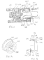
- FIG. 2 a cross-sectional view is provided of a portion of a neutron generator 200 utilizing a resistorized annular ceramic washer 267 according to one embodiment of the invention.
- Fig. 2 shows the same portion of the neutron generator seen in Fig. 1a , and similar elements are identified with similar numbers increased by "100".
- PNG 200 has a target 244 with front face 245.
- a suppressor electrode 246 is provided with an on-axis beam spot opening surrounding the target. The suppressor electrode sits within the evacuated ceramic tube 248 and is connected to the corona shield 261 at flange 246a.
- the resistorized ceramic washer 267 is coupled between the suppressor electrode flange 246a and the rear portion of the target 244 (i.e., rearward of the target face 245).
- the sole purpose of the resistorized ceramic washer 267 is to provide a desirably resistive electrical path 287 between the suppressor electrode 246 and the target 244, thereby establishing the (high) voltage of the target.
- the resistorized ceramic washer 267 does not directly affect the ion beam.
- provision of the resistorized ceramic washer 267 eliminates the need for the separate resistor, spring, and insulating sleeve surrounding the resistor and spring as provided in the prior art ( Fig. 1a ).
- the thick film resistance of the washer can be well-defined and not affected during manufacture, is protected during assembly and use, and is rugged in that it has no moving parts.
- metal washer 282 is preferably brazed to the ceramic washer 267 (prior to the ceramic washer 267 being resistorized) and is in contact with the corona shield 261.
- metal washer 284 is preferably brazed to the ceramic washer 267 (prior to the ceramic washer 267 being resistorized) and is in (metal-to-metal) contact (e.g., welded) with the target 244. It is noted that the target 244 is held in place by screw 270 which is electrically insulated from the corona shield 261 by an insulating washer 272.
- an insulating washer 266 is located between the corona shield 261 and the back face of the target 244.
- the corona shield is shown to extend around the target 244 and is circumferentially insulated from the target by an optional insulator (tape) 269.
- the suppressor electrode 246 is shown to extend rearward of flange 246a, thereby supplying a sputter shield to the resistorized ceramic washer 267.
- resistorized ceramic washer 267 of Fig. 2 with the metal washers 282, 284 welded thereto are seen in Figs. 3a and 3b . More particularly, resistorized ceramic washer 267 is an annular washer having inner and outer cylindrical surfaces 267a, 267b and first and second end annular surfaces 267c, 267d, and a winding serpentine path thick film resistor 287 is located on the inner surface 267a.
- the material of the thick film resistor 287 is preferably selected from a ceramic-metal (cermet) material such as ruthenium dioxide (RuO 2 ) - lead borosilicate glass system, or barium tantalite (BaTa 2 O 6 ) - borosilicate glass system, although other materials (cermet or otherwise) can be utilized.
- the resistive film is laid down as a flowable paste and cured in place, e.g., by sintering. Curing the resistive thick film causes the resistor to be integrally formed on the ceramic.
- the thick film can be encapsulated or coated with a protective non- conductive material such as glass frit or spray-on ceramic.
- the thick film path has a high resistance (for purposes herein "high resistance” being at least 1 MOhm), although depending upon the operating duty cycle, the geometry and other operating and physical details of the PNG, other resistances might be in order.
- the thick film path 287 could have a resistance of between 5 MOhm and 15 MOhm.
- the thickness (height) and width of the thick film (ink), and length of the serpentine thick film path is selected.
- a typical thick film path thickness is approximately 0.0005 inches(0.0127mm), although it may vary by several orders of magnitude.
- a typical thick film path width is approximately 0.002 inches (0.0508mm), although it may vary by several orders of magnitude.
- the path length is preferably several inches, although again, it may vary by one or more orders of magnitude depending upon the width, length, and desired resistance.
- the thick film path is recessed in a groove (not shown) in the resistorized ceramic washer 267
- the resistorized ceramic washer 267 may be metallized on each end 267c, 267d to provide pad surfaces 288a, 288b for contact with metal washers 282, 284. Where pad surfaces 288a and 288b are provided, the thick film path 287 electrically connects one pad to the other.
- the resistorized ceramic washer may be also metallized on a portion of its outer surface 267b to provide a pad surface 288c for contact with metal washer 282.
- one or both of the metal washers 282, 284 may be provided with metal tabs 291 (as seen in Fig. 3c ) for making contact with the thick film path.
- the metal washers 282, 284 are brazed to the ceramic washer 267 (before it is resistorized). Brazing may be accomplished through the use of a material such as KOVAR or by other techniques known in the art.
- metal washer 282 has an annular front flange 282a defining an inner diameter approximately equal to the inner diameter of the resistorized ceramic washer 267 and an outer diameter that is larger than the outer diameter of the resistorized ceramic washer 267.
- the outer surface of the annular front flange is intended to be in contact with the corona shield 261 of the PNG.
- Extending perpendicularly from the annular front flange is a circumferential axial flange 282b which is intended to engage the outer cylindrical surface 267b of the ceramic washer 267.
- the engagement between axial flange 282b and the outer cylindrical surface 267b of the ceramic washer 267 provides alignment for brazing, or coupling by other means known in the art. Other geometric arrangements of contacting the corona shield are possible and known to those skilled in the art.
- metal washer 284 is grommet-shaped with end flanges 284a, 284b and an axial wall 284c connecting them.
- Flange 284a is intended to contact the second end ring (annular) surface 267d of the resistorized ceramic washer 267R and has an outer diameter substantially equal to the outer diameter of the ceramic washer 267.
- Flange 284b is intended to contact the target 244.
- the ceramic washer 267 has an inner diameter of approximately 0.70 inches (17.78mm), an outer diameter of approximately 0.88 inches (22.352mm), and a height of approximately 0.25 inches (6.35mm), although it will be appreciated that other sizes are possible and encompassed by the invention.
- Resistorized annular ceramic washer 367 is similar to the resistorized ceramic washer 267 of Figs. 3a and 3b (with like parts denoted by numbers increased by "100") except that instead of the thick- film path assuming a serpentine arrangement, the thick-film path 387 of washer 367 on the inner cylindrical surface 367a assumes a winding helical arrangement. In both cases, the width of the path is small compared to the length of the path.
- the height of the cylinder defined cylindrical surfaces 367a, 367b is smaller than the height of the cylinder defined by cylindrical surfaces 267a, 267b.
- FIG. 5 a portion of another embodiment of a PNG 400 which utilizes a resistorized ceramic washer 466R is shown, with elements similar to the PNG of Fig. 1a increased by "300".
- PNG 400 has a target 444 and corona shield 461 separated circumferentially by optional resistive tape 469 and separated axially by a resistorized ceramic washer 466R.
- the corona shield 461 is shown to extend from one side of the resistorized ceramic washer 466R and around the ceramic washer 466R and around the target 444.
- Resistorized ceramic washer 466R electrically insulates the target 444 from the corona shield 461, except that resistorized washer 466R provides a high resistance electrical path 487 (such as path 287 of Fig. 3a or path 387 of Fig. 4 ) on its inner surface which runs between the corona shield 461 and the target 444, thereby establishing the (high) voltage of the target.
- the end/disc faces of the resistorized ceramic washer 466R are preferably metallised and connected to the thick film resistor 487. Provision of the resistorized ceramic washer 466R eliminates the need for the separate resistor, spring, and insulating sleeve surrounding the resistor and spring as provided in the prior art ( Fig. 1a ).
- the resistorized washer 466R is adapted with a hole to receive the screw 470 which engages and supports the target 444.
- the screw 470 is electrically insulated from the corona shield 461 by insulating washer 472.
- the inside hole of the ceramic washer 466R on which the thick film resistor path is provided is sufficiently large so that the screw 470 passes through the washer with significant clearance between the screw and the resistorized thick film path 487. Because the resistorized ceramic washer 466R of PNG 400 is not located inside the sealed evacuated tube portion of the PNC, it can be readily replaced if it fails. However, it may be subject to different atmospheres and processes during manufacture and operation of the PNG. Therefore, according to one embodiment of the invention, the high resistance electrical path 487 is optionally coated with glass or another non-conductive, generally inert coating.
Landscapes
- Physics & Mathematics (AREA)
- Spectroscopy & Molecular Physics (AREA)
- High Energy & Nuclear Physics (AREA)
- Engineering & Computer Science (AREA)
- Plasma & Fusion (AREA)
- Chemical & Material Sciences (AREA)
- Analytical Chemistry (AREA)
- Details Of Resistors (AREA)
- Apparatuses And Processes For Manufacturing Resistors (AREA)
Claims (16)
- Neutronenerzeuger-(200, 400)Anordnung, die umfasst:eine Hochspannungselektrode (246, 261, 461);ein Ionenstrahl-Target (244, 444) zum Erzeugen von Neutronen, das auf eine Spannung gelegt werden soll;einen von der Hochspannungselektrode (246, 261, 461) umfassten und das Ionenstrahl-Target (244, 444) umschließenden Sprühschutz (261, 461);eine ringförmige Keramikscheibe (267, 466R) mit einer zylindrischen Innenoberfläche und Außenoberfläche (267a, 267b), einer ersten und zweiten ringförmigen Endfläche (267c, 267d) und einem einstückig an der Innenoberfläche (267a) ausgebildeten hochohmigen, in gewundenem Pfad verlaufenden Dickschichtwiderstand (287, 487);eine erste Metallscheibe (282) in elektrischem Kontakt mit dem Sprühschutz (261, 461), die mit der ersten ringförmigen Endfläche (267c) gekoppelt und elektrisch mit dem in gewundenem Pfad verlaufenden Dickschichtwiderstand (287, 487) verbunden ist; undeine zweite Metallscheibe (284) in elektrischem Kontakt mit dem Ionenstrahl-Target (244, 444), die mit der zweiten ringförmigen Endfläche (267d) gekoppelt und elektrisch mit dem in gewundenem Pfad verlaufenden Dickschichtwiderstand (287, 487) verbunden ist;wobei der Dickschichtwiderstand (287, 487) einen Wirkwiderstand aufweist, der so gewählt ist, dass er das Ionenstrahl-Target (244, 444) auf die Spannung legt und die Hochspannungselektrode (246, 261, 461) und das Ionenstrahl-Target (244, 444) elektrisch verbindet.
- Anordnung gemäß Anspruch 1, wobei:
die erste Metallscheibe (282) an die erste ringförmige Endfläche (267c) hartgelötet ist und die zweite Metallscheibe (284) an die zweite ringförmige Endfläche (267d) hartgelötet ist. - Anordnung gemäß Anspruch 1, wobei:
der in gewundenem Pfad verlaufende Dickschichtwiderstand (287) einen schlangenförmigen Pfad aufweist. - Anordnung gemäß Anspruch 1, wobei:
der in gewundenem Pfad verlaufende Dickschichtwiderstand (287) einen wendelförmigen Pfad aufweist. - Anordnung gemäß Anspruch 1, wobei:
die ringförmige Keramikscheibe (267) auf wenigstens einer aus der ersten und zweiten ringförmigen Endfläche (267a, 267b) metallisiert ist. - Anordnung gemäß Anspruch 1, wobei:
der in gewundenem Pfad verlaufende hochohmige Dickschichtwiderstand (287) einen Wirkwiderstand zwischen 5 MOhm und 15 MOhm aufweist. - Anordnung gemäß Anspruch 1, wobei:
der in gewundenem Pfad verlaufende hochohmige Dickschichtwiderstand (287) ein Keramik-Metall-Material umfasst. - Anordnung gemäß Anspruch 1, wobei:
die Anordnung eine Vakuumröhrenkonstruktion (248) umfasst, und sich die ringförmige Keramikscheibe (267) in der Vakuumröhrenkonstruktion (248) befindet. - Anordnung gemäß Anspruch 8, wobei:
die ringförmige Keramikscheibe (267) an die Vakuumröhrenkonstruktion (248) geschweißt ist. - Anordnung gemäß Anspruch 8, wobei:
die Hochspannungselektrode (246, 261) eine Supressorelektrode (246) umfasst. - Anordnung gemäß Anspruch 10, wobei:
die Supressorelektrode (246) sich zwischen dem Target (244) und der ringförmigen Keramikscheibe (267) erstreckt. - Anordnung gemäß Anspruch 1, die ferner umfasst:
eine Schraube (470), wobei die ringförmige Keramikscheibe (466R) einen Ringraum aufweist und das Target (444) eine Vorderseite und einen von der Vorderseite distalen Rückseitenabschnitt aufweist, und die Schraube (470) sich, ohne die ringförmige Keramikscheibe (466R) zu berühren, durch den Ringraum der ringförmigen Keramikscheibe (466R) hindurch und in den Rückseitenabschnitt des Targets (444) erstreckt. - Anordnung gemäß Anspruch 12, wobei:
die Hochspannungselektrode sich von außerhalb von der zweiten ringförmigen Endfläche um die zylindrische Außenfläche und über die erste ringförmige Außenfläche hinaus und um das Target (444) herum erstreckt. - Verfahren zum Herstellen einer Anordnung gemäß Anspruch 11, das umfasst:Ablegen einer fließfähigen Paste auf die Innenoberfläche (267a) der ringförmigen Keramikscheibe (267), um die Dickschicht auszubilden, wobei die ringförmige Keramikscheibe die zylindrische Innenoberfläche und Außenoberfläche (267a, 267b) und die erste und zweite ringförmige Endfläche (267c, 267d) aufweist;Aushärten der Dickschicht an Ort und Stelle, um den Widerstand (287) einstückig an der Keramikscheibe (267) auszubilden;Koppeln der ersten Metallscheibe (282) mit der ersten ringförmigen Endfläche (267c), um die erste Metallscheibe (282) elektrisch mit dem in gewundenem Pfad verlaufenden Dickschichtwiderstand (287) zu verbinden; undKoppeln der ersten Metallscheibe (284) mit der zweiten ringförmigen Endfläche (267d), um die zweite Metallscheibe (284) elektrisch mit dem in gewundenem Pfad verlaufenden Dickschichtwiderstand (287) zu verbinden;Platzieren der ringförmigen Keramikscheibe (267) in die Vakuumröhrenkonstruktion (248), wobei die Hochspannungselektrode (246, 261) die Supressorelektrode (246) umfasst, die sich innerhalb der Vakuumröhrenkonstruktion (248) befindet;Koppeln der ringförmigen Keramikscheibe (267) zwischen einen Flansch (246a) an der Supressorelektrode (246) und einen rückwärtigen Abschnitt des Ionenstrahl-Targets (244), so dass die Supressorelektrode (246) sich zwischen dem Ionenstrahl-Target (244) und der ringförmigen Keramikscheibe (267) erstreckt, wobei die erste Metallscheibe (282) elektrisch mit dem Sprühschutz (261) verbunden ist und wobei die zweite Metallscheibe (284) elektrisch mit dem Ionenstrahl-Target (244) verbunden ist;wobei der Dickschichtwiderstand (287) den Wirkwiderstand aufweist, der so gewählt ist, dass er das Ionenstrahl-Target (244) auf die Spannung legt und die Hochspannungselektrode (246, 261) und das Ionenstrahl-Target (244) elektrisch verbindet.
- Verfahren gemäß Anspruch 14, wobei der Schritt des Aushärtens der Dickschicht an Ort und Stelle, um den Widerstand (287) einstückig an der Keramikscheibe (267) auszubilden, umfasst, die Paste zu sintern.
- Verfahren gemäß Anspruch 14 oder 15, das ferner umfasst, nach dem Aushärten der Paste die Dickschicht mit einem nichtleitenden Schutzmaterial zu kapseln oder zu beschichten, wobei das Schutzmaterial wahlweise Glasfritte oder Sprühkeramik umfasst.
Applications Claiming Priority (2)
| Application Number | Priority Date | Filing Date | Title |
|---|---|---|---|
| US40721910P | 2010-10-27 | 2010-10-27 | |
| PCT/US2011/058064 WO2012058414A2 (en) | 2010-10-27 | 2011-10-27 | Thick-film resistorized ceramic insulators for sealed high voltage tube electrodes |
Publications (3)
| Publication Number | Publication Date |
|---|---|
| EP2656355A2 EP2656355A2 (de) | 2013-10-30 |
| EP2656355A4 EP2656355A4 (de) | 2014-09-17 |
| EP2656355B1 true EP2656355B1 (de) | 2019-07-17 |
Family
ID=45994751
Family Applications (1)
| Application Number | Title | Priority Date | Filing Date |
|---|---|---|---|
| EP11837079.0A Not-in-force EP2656355B1 (de) | 2010-10-27 | 2011-10-27 | Neutronengenerator mit keramischen dickschicht-widerstandsisolatoren für versiegelte hochspannungsröhrenelektroden |
Country Status (3)
| Country | Link |
|---|---|
| US (1) | US9384932B2 (de) |
| EP (1) | EP2656355B1 (de) |
| WO (1) | WO2012058414A2 (de) |
Families Citing this family (5)
| Publication number | Priority date | Publication date | Assignee | Title |
|---|---|---|---|---|
| WO2015100233A2 (en) * | 2013-12-24 | 2015-07-02 | Waters Technologies Corporation | Atmospheric interface for electrically grounded electrospray |
| US9389334B2 (en) | 2014-11-13 | 2016-07-12 | Schlumberger Technology Corporation | Radiation generator having an actively evacuated acceleration column |
| US20170080514A1 (en) * | 2015-09-17 | 2017-03-23 | Caterpillar Inc. | Insulator for welding a boss onto a member |
| US20230380046A1 (en) * | 2022-05-17 | 2023-11-23 | Halliburton Energy Services, Inc. | Ion source for neutron generator usable in wellbore |
| US20240373541A1 (en) * | 2023-05-02 | 2024-11-07 | Halliburton Energy Services, Inc. | Construction Of A Target Assembly For A Compact D-D Or D-T Neutron Generator |
Family Cites Families (17)
| Publication number | Priority date | Publication date | Assignee | Title |
|---|---|---|---|---|
| US3775216A (en) | 1967-03-31 | 1973-11-27 | Schlumberger Technology Corp | Neutron generating systems |
| DE3116169A1 (de) * | 1981-04-23 | 1982-11-11 | Philips Patentverwaltung Gmbh, 2000 Hamburg | Hochspannungs-vakuumroehre, insbesondere roentgenroehre |
| DE3142281A1 (de) | 1981-10-24 | 1983-05-05 | Philips Patentverwaltung Gmbh, 2000 Hamburg | Roentgenroehre mit einem metallteil und einer gegenueber dem metallteil positive hochspannung fuehrenden elektrode |
| US4599542A (en) | 1983-07-30 | 1986-07-08 | English Electric Valve Company Limited | Linear beam tubes |
| US4866411A (en) * | 1988-03-25 | 1989-09-12 | Caddock Richard E | Film-type cylindrical resistor, and method of making it |
| JPH02163901A (ja) * | 1988-12-16 | 1990-06-25 | Murata Mfg Co Ltd | 抵抗器及びその製造方法 |
| US5231372A (en) * | 1991-10-09 | 1993-07-27 | Caddock Electronics, Inc. | Method of manufacturing high-voltage and/or high-power thick-film screen-printed cylindrical resistors having small sizes, low voltage coefficients, and low inductance, and resistor thus manufactured |
| US5293410A (en) * | 1991-11-27 | 1994-03-08 | Schlumberger Technology Corporation | Neutron generator |
| US5426345A (en) * | 1994-01-18 | 1995-06-20 | Andrex Radiation Products A/S | High voltage electronic tube with intermediate electrode |
| JP2000021601A (ja) * | 1998-07-07 | 2000-01-21 | Hokuriku Electric Ind Co Ltd | 抵抗器とその製造方法 |
| JP2005041712A (ja) * | 2003-07-23 | 2005-02-17 | Kyocera Corp | セラミックチャンバー |
| US7142639B2 (en) * | 2004-04-19 | 2006-11-28 | Varian Medical Systems Technologies, Inc. | High voltage connector for x-ray tube |
| KR20080043268A (ko) * | 2005-06-21 | 2008-05-16 | 로무 가부시키가이샤 | 칩 저항기 및 그 제조 방법 |
| FR2909251B1 (fr) * | 2006-11-28 | 2009-01-16 | Gen Electric | Generateur de haute tension d'un appareil a rayons x comportant un dispositif de mesure de haute tension |
| JP5386080B2 (ja) | 2007-12-21 | 2014-01-15 | 株式会社日立製作所 | 厚膜抵抗体 |
| DE102007063282A1 (de) * | 2007-12-27 | 2009-07-02 | Robert Bosch Gmbh | Verfahren zur Herstellung eines elektrischen Leiters durch Auftragen zumindest einer Paste, insbesondere Dickschichtpaste |
| EP2801098A4 (de) | 2012-01-04 | 2015-06-24 | Services Petroliers Schlumberger | Hochspannungswiderstand und herstellungsverfahren dafür |
-
2011
- 2011-10-27 WO PCT/US2011/058064 patent/WO2012058414A2/en not_active Ceased
- 2011-10-27 US US13/881,347 patent/US9384932B2/en active Active
- 2011-10-27 EP EP11837079.0A patent/EP2656355B1/de not_active Not-in-force
Non-Patent Citations (1)
| Title |
|---|
| None * |
Also Published As
| Publication number | Publication date |
|---|---|
| EP2656355A2 (de) | 2013-10-30 |
| US20130293091A1 (en) | 2013-11-07 |
| WO2012058414A2 (en) | 2012-05-03 |
| EP2656355A4 (de) | 2014-09-17 |
| US9384932B2 (en) | 2016-07-05 |
| WO2012058414A3 (en) | 2012-08-02 |
Similar Documents
| Publication | Publication Date | Title |
|---|---|---|
| US9384932B2 (en) | Thick-film resistorized ceramic insulators for sealed high voltage tube electrodes | |
| JP3122172B2 (ja) | リニアな軸方向及び半径方向のフィールドを持った静電粒子加速器 | |
| US9048058B2 (en) | Radiation generating tube and radiation generating apparatus using the same | |
| JP5566440B2 (ja) | ガス放電管 | |
| US9603233B2 (en) | Particle accelerator with a heat pipe supporting components of a high voltage power supply | |
| JPH01143198A (ja) | 粒子加速器 | |
| EP3637960A1 (de) | Röntgenstrahlerzeugungsvorrichtung | |
| US2828433A (en) | Electron gun construction | |
| US2644907A (en) | Electron tube | |
| RU2434369C2 (ru) | Структура бетатрона и способ производства структуры бетатрона | |
| US20070237281A1 (en) | Neutron generator tube having reduced internal voltage gradients and longer lifetime | |
| US7135670B2 (en) | Photomultiplier and radiation detector | |
| US3662212A (en) | Depressed electron beam collector | |
| CN218769396U (zh) | 分压检测集成型x射线管器件 | |
| KR20160059282A (ko) | 절연성 강화 초소형 엑스선관 | |
| US5790362A (en) | Lightning arrester | |
| JP2591068B2 (ja) | 避雷器 | |
| JPS5826143B2 (ja) | ガンマ線補償型電離箱 | |
| KR102775447B1 (ko) | 엑스레이 튜브 | |
| US7550909B2 (en) | Electron gun providing improved thermal isolation | |
| US5550430A (en) | Gas discharge closing switch with unitary ceramic housing | |
| US20130256521A1 (en) | Well-logging apparatus with ring-shaped resistors and related methods | |
| US20060091316A1 (en) | Photomultiplier and radiation detector | |
| US7132639B2 (en) | Photomultiplier and radiation detector | |
| US2486292A (en) | Cathode structure for electric discharge tubes |
Legal Events
| Date | Code | Title | Description |
|---|---|---|---|
| PUAI | Public reference made under article 153(3) epc to a published international application that has entered the european phase |
Free format text: ORIGINAL CODE: 0009012 |
|
| 17P | Request for examination filed |
Effective date: 20130517 |
|
| AK | Designated contracting states |
Kind code of ref document: A2 Designated state(s): AL AT BE BG CH CY CZ DE DK EE ES FI FR GB GR HR HU IE IS IT LI LT LU LV MC MK MT NL NO PL PT RO RS SE SI SK SM TR |
|
| DAX | Request for extension of the european patent (deleted) | ||
| A4 | Supplementary search report drawn up and despatched |
Effective date: 20140820 |
|
| STAA | Information on the status of an ep patent application or granted ep patent |
Free format text: STATUS: EXAMINATION IS IN PROGRESS |
|
| 17Q | First examination report despatched |
Effective date: 20171107 |
|
| REG | Reference to a national code |
Ref country code: DE Ref legal event code: R079 Ref document number: 602011060565 Country of ref document: DE Free format text: PREVIOUS MAIN CLASS: G21G0004020000 Ipc: H01J0003020000 |
|
| RIC1 | Information provided on ipc code assigned before grant |
Ipc: H01J 3/02 20060101AFI20180808BHEP Ipc: H01C 3/14 20060101ALI20180808BHEP Ipc: H01J 29/48 20060101ALI20180808BHEP Ipc: H01J 37/248 20060101ALI20180808BHEP Ipc: H01J 35/02 20060101ALI20180808BHEP Ipc: H01J 29/96 20060101ALI20180808BHEP Ipc: H01J 31/50 20060101ALI20180808BHEP Ipc: H05H 3/06 20060101ALI20180808BHEP |
|
| GRAP | Despatch of communication of intention to grant a patent |
Free format text: ORIGINAL CODE: EPIDOSNIGR1 |
|
| STAA | Information on the status of an ep patent application or granted ep patent |
Free format text: STATUS: GRANT OF PATENT IS INTENDED |
|
| INTG | Intention to grant announced |
Effective date: 20181008 |
|
| RAP1 | Party data changed (applicant data changed or rights of an application transferred) |
Owner name: PRAD RESEARCH AND DEVELOPMENT LIMITED Owner name: SCHLUMBERGER TECHNOLOGY B.V. Owner name: SERVICES PETROLIERS SCHLUMBERGER Owner name: SCHLUMBERGER HOLDINGS LIMITED |
|
| GRAS | Grant fee paid |
Free format text: ORIGINAL CODE: EPIDOSNIGR3 |
|
| GRAA | (expected) grant |
Free format text: ORIGINAL CODE: 0009210 |
|
| STAA | Information on the status of an ep patent application or granted ep patent |
Free format text: STATUS: THE PATENT HAS BEEN GRANTED |
|
| AK | Designated contracting states |
Kind code of ref document: B1 Designated state(s): AL AT BE BG CH CY CZ DE DK EE ES FI FR GB GR HR HU IE IS IT LI LT LU LV MC MK MT NL NO PL PT RO RS SE SI SK SM TR |
|
| RAP1 | Party data changed (applicant data changed or rights of an application transferred) |
Owner name: SERVICES PETROLIERS SCHLUMBERGER Owner name: SCHLUMBERGER TECHNOLOGY B.V. Owner name: PRAD RESEARCH AND DEVELOPMENT LIMITED Owner name: SCHLUMBERGER HOLDINGS LIMITED |
|
| REG | Reference to a national code |
Ref country code: GB Ref legal event code: FG4D |
|
| REG | Reference to a national code |
Ref country code: CH Ref legal event code: EP |
|
| REG | Reference to a national code |
Ref country code: IE Ref legal event code: FG4D |
|
| REG | Reference to a national code |
Ref country code: DE Ref legal event code: R096 Ref document number: 602011060565 Country of ref document: DE |
|
| REG | Reference to a national code |
Ref country code: AT Ref legal event code: REF Ref document number: 1156612 Country of ref document: AT Kind code of ref document: T Effective date: 20190815 |
|
| REG | Reference to a national code |
Ref country code: NL Ref legal event code: MP Effective date: 20190717 |
|
| REG | Reference to a national code |
Ref country code: NO Ref legal event code: T2 Effective date: 20190717 |
|
| REG | Reference to a national code |
Ref country code: LT Ref legal event code: MG4D |
|
| REG | Reference to a national code |
Ref country code: AT Ref legal event code: MK05 Ref document number: 1156612 Country of ref document: AT Kind code of ref document: T Effective date: 20190717 |
|
| PG25 | Lapsed in a contracting state [announced via postgrant information from national office to epo] |
Ref country code: NL Free format text: LAPSE BECAUSE OF FAILURE TO SUBMIT A TRANSLATION OF THE DESCRIPTION OR TO PAY THE FEE WITHIN THE PRESCRIBED TIME-LIMIT Effective date: 20190717 Ref country code: PT Free format text: LAPSE BECAUSE OF FAILURE TO SUBMIT A TRANSLATION OF THE DESCRIPTION OR TO PAY THE FEE WITHIN THE PRESCRIBED TIME-LIMIT Effective date: 20191118 Ref country code: SE Free format text: LAPSE BECAUSE OF FAILURE TO SUBMIT A TRANSLATION OF THE DESCRIPTION OR TO PAY THE FEE WITHIN THE PRESCRIBED TIME-LIMIT Effective date: 20190717 Ref country code: BG Free format text: LAPSE BECAUSE OF FAILURE TO SUBMIT A TRANSLATION OF THE DESCRIPTION OR TO PAY THE FEE WITHIN THE PRESCRIBED TIME-LIMIT Effective date: 20191017 Ref country code: LT Free format text: LAPSE BECAUSE OF FAILURE TO SUBMIT A TRANSLATION OF THE DESCRIPTION OR TO PAY THE FEE WITHIN THE PRESCRIBED TIME-LIMIT Effective date: 20190717 Ref country code: HR Free format text: LAPSE BECAUSE OF FAILURE TO SUBMIT A TRANSLATION OF THE DESCRIPTION OR TO PAY THE FEE WITHIN THE PRESCRIBED TIME-LIMIT Effective date: 20190717 Ref country code: FI Free format text: LAPSE BECAUSE OF FAILURE TO SUBMIT A TRANSLATION OF THE DESCRIPTION OR TO PAY THE FEE WITHIN THE PRESCRIBED TIME-LIMIT Effective date: 20190717 Ref country code: AT Free format text: LAPSE BECAUSE OF FAILURE TO SUBMIT A TRANSLATION OF THE DESCRIPTION OR TO PAY THE FEE WITHIN THE PRESCRIBED TIME-LIMIT Effective date: 20190717 |
|
| PG25 | Lapsed in a contracting state [announced via postgrant information from national office to epo] |
Ref country code: IS Free format text: LAPSE BECAUSE OF FAILURE TO SUBMIT A TRANSLATION OF THE DESCRIPTION OR TO PAY THE FEE WITHIN THE PRESCRIBED TIME-LIMIT Effective date: 20191117 Ref country code: LV Free format text: LAPSE BECAUSE OF FAILURE TO SUBMIT A TRANSLATION OF THE DESCRIPTION OR TO PAY THE FEE WITHIN THE PRESCRIBED TIME-LIMIT Effective date: 20190717 Ref country code: ES Free format text: LAPSE BECAUSE OF FAILURE TO SUBMIT A TRANSLATION OF THE DESCRIPTION OR TO PAY THE FEE WITHIN THE PRESCRIBED TIME-LIMIT Effective date: 20190717 Ref country code: AL Free format text: LAPSE BECAUSE OF FAILURE TO SUBMIT A TRANSLATION OF THE DESCRIPTION OR TO PAY THE FEE WITHIN THE PRESCRIBED TIME-LIMIT Effective date: 20190717 Ref country code: GR Free format text: LAPSE BECAUSE OF FAILURE TO SUBMIT A TRANSLATION OF THE DESCRIPTION OR TO PAY THE FEE WITHIN THE PRESCRIBED TIME-LIMIT Effective date: 20191018 Ref country code: RS Free format text: LAPSE BECAUSE OF FAILURE TO SUBMIT A TRANSLATION OF THE DESCRIPTION OR TO PAY THE FEE WITHIN THE PRESCRIBED TIME-LIMIT Effective date: 20190717 |
|
| PG25 | Lapsed in a contracting state [announced via postgrant information from national office to epo] |
Ref country code: TR Free format text: LAPSE BECAUSE OF FAILURE TO SUBMIT A TRANSLATION OF THE DESCRIPTION OR TO PAY THE FEE WITHIN THE PRESCRIBED TIME-LIMIT Effective date: 20190717 |
|
| PG25 | Lapsed in a contracting state [announced via postgrant information from national office to epo] |
Ref country code: DK Free format text: LAPSE BECAUSE OF FAILURE TO SUBMIT A TRANSLATION OF THE DESCRIPTION OR TO PAY THE FEE WITHIN THE PRESCRIBED TIME-LIMIT Effective date: 20190717 Ref country code: PL Free format text: LAPSE BECAUSE OF FAILURE TO SUBMIT A TRANSLATION OF THE DESCRIPTION OR TO PAY THE FEE WITHIN THE PRESCRIBED TIME-LIMIT Effective date: 20190717 Ref country code: EE Free format text: LAPSE BECAUSE OF FAILURE TO SUBMIT A TRANSLATION OF THE DESCRIPTION OR TO PAY THE FEE WITHIN THE PRESCRIBED TIME-LIMIT Effective date: 20190717 Ref country code: RO Free format text: LAPSE BECAUSE OF FAILURE TO SUBMIT A TRANSLATION OF THE DESCRIPTION OR TO PAY THE FEE WITHIN THE PRESCRIBED TIME-LIMIT Effective date: 20190717 Ref country code: IT Free format text: LAPSE BECAUSE OF FAILURE TO SUBMIT A TRANSLATION OF THE DESCRIPTION OR TO PAY THE FEE WITHIN THE PRESCRIBED TIME-LIMIT Effective date: 20190717 |
|
| PG25 | Lapsed in a contracting state [announced via postgrant information from national office to epo] |
Ref country code: MC Free format text: LAPSE BECAUSE OF FAILURE TO SUBMIT A TRANSLATION OF THE DESCRIPTION OR TO PAY THE FEE WITHIN THE PRESCRIBED TIME-LIMIT Effective date: 20190717 Ref country code: IS Free format text: LAPSE BECAUSE OF FAILURE TO SUBMIT A TRANSLATION OF THE DESCRIPTION OR TO PAY THE FEE WITHIN THE PRESCRIBED TIME-LIMIT Effective date: 20200224 Ref country code: SM Free format text: LAPSE BECAUSE OF FAILURE TO SUBMIT A TRANSLATION OF THE DESCRIPTION OR TO PAY THE FEE WITHIN THE PRESCRIBED TIME-LIMIT Effective date: 20190717 Ref country code: CZ Free format text: LAPSE BECAUSE OF FAILURE TO SUBMIT A TRANSLATION OF THE DESCRIPTION OR TO PAY THE FEE WITHIN THE PRESCRIBED TIME-LIMIT Effective date: 20190717 Ref country code: SK Free format text: LAPSE BECAUSE OF FAILURE TO SUBMIT A TRANSLATION OF THE DESCRIPTION OR TO PAY THE FEE WITHIN THE PRESCRIBED TIME-LIMIT Effective date: 20190717 |
|
| REG | Reference to a national code |
Ref country code: CH Ref legal event code: PL |
|
| REG | Reference to a national code |
Ref country code: DE Ref legal event code: R097 Ref document number: 602011060565 Country of ref document: DE |
|
| PLBE | No opposition filed within time limit |
Free format text: ORIGINAL CODE: 0009261 |
|
| STAA | Information on the status of an ep patent application or granted ep patent |
Free format text: STATUS: NO OPPOSITION FILED WITHIN TIME LIMIT |
|
| PG2D | Information on lapse in contracting state deleted |
Ref country code: IS |
|
| PG25 | Lapsed in a contracting state [announced via postgrant information from national office to epo] |
Ref country code: LU Free format text: LAPSE BECAUSE OF NON-PAYMENT OF DUE FEES Effective date: 20191027 Ref country code: LI Free format text: LAPSE BECAUSE OF NON-PAYMENT OF DUE FEES Effective date: 20191031 Ref country code: CH Free format text: LAPSE BECAUSE OF NON-PAYMENT OF DUE FEES Effective date: 20191031 |
|
| 26N | No opposition filed |
Effective date: 20200603 |
|
| REG | Reference to a national code |
Ref country code: BE Ref legal event code: MM Effective date: 20191031 |
|
| PG25 | Lapsed in a contracting state [announced via postgrant information from national office to epo] |
Ref country code: SI Free format text: LAPSE BECAUSE OF FAILURE TO SUBMIT A TRANSLATION OF THE DESCRIPTION OR TO PAY THE FEE WITHIN THE PRESCRIBED TIME-LIMIT Effective date: 20190717 Ref country code: BE Free format text: LAPSE BECAUSE OF NON-PAYMENT OF DUE FEES Effective date: 20191031 |
|
| PG25 | Lapsed in a contracting state [announced via postgrant information from national office to epo] |
Ref country code: IE Free format text: LAPSE BECAUSE OF NON-PAYMENT OF DUE FEES Effective date: 20191027 Ref country code: FR Free format text: LAPSE BECAUSE OF NON-PAYMENT OF DUE FEES Effective date: 20191031 |
|
| PG25 | Lapsed in a contracting state [announced via postgrant information from national office to epo] |
Ref country code: CY Free format text: LAPSE BECAUSE OF FAILURE TO SUBMIT A TRANSLATION OF THE DESCRIPTION OR TO PAY THE FEE WITHIN THE PRESCRIBED TIME-LIMIT Effective date: 20190717 |
|
| PG25 | Lapsed in a contracting state [announced via postgrant information from national office to epo] |
Ref country code: HU Free format text: LAPSE BECAUSE OF FAILURE TO SUBMIT A TRANSLATION OF THE DESCRIPTION OR TO PAY THE FEE WITHIN THE PRESCRIBED TIME-LIMIT; INVALID AB INITIO Effective date: 20111027 Ref country code: MT Free format text: LAPSE BECAUSE OF FAILURE TO SUBMIT A TRANSLATION OF THE DESCRIPTION OR TO PAY THE FEE WITHIN THE PRESCRIBED TIME-LIMIT Effective date: 20190717 |
|
| PGFP | Annual fee paid to national office [announced via postgrant information from national office to epo] |
Ref country code: GB Payment date: 20210915 Year of fee payment: 11 |
|
| PGFP | Annual fee paid to national office [announced via postgrant information from national office to epo] |
Ref country code: NO Payment date: 20211011 Year of fee payment: 11 Ref country code: DE Payment date: 20210914 Year of fee payment: 11 |
|
| PG25 | Lapsed in a contracting state [announced via postgrant information from national office to epo] |
Ref country code: MK Free format text: LAPSE BECAUSE OF FAILURE TO SUBMIT A TRANSLATION OF THE DESCRIPTION OR TO PAY THE FEE WITHIN THE PRESCRIBED TIME-LIMIT Effective date: 20190717 |
|
| REG | Reference to a national code |
Ref country code: DE Ref legal event code: R119 Ref document number: 602011060565 Country of ref document: DE |
|
| REG | Reference to a national code |
Ref country code: NO Ref legal event code: MMEP |
|
| GBPC | Gb: european patent ceased through non-payment of renewal fee |
Effective date: 20221027 |
|
| PG25 | Lapsed in a contracting state [announced via postgrant information from national office to epo] |
Ref country code: NO Free format text: LAPSE BECAUSE OF NON-PAYMENT OF DUE FEES Effective date: 20221031 Ref country code: DE Free format text: LAPSE BECAUSE OF NON-PAYMENT OF DUE FEES Effective date: 20230503 |
|
| PG25 | Lapsed in a contracting state [announced via postgrant information from national office to epo] |
Ref country code: GB Free format text: LAPSE BECAUSE OF NON-PAYMENT OF DUE FEES Effective date: 20221027 |