EP2656033B1 - Dispositif de mesure optique - Google Patents
Dispositif de mesure optique Download PDFInfo
- Publication number
- EP2656033B1 EP2656033B1 EP11811423.0A EP11811423A EP2656033B1 EP 2656033 B1 EP2656033 B1 EP 2656033B1 EP 11811423 A EP11811423 A EP 11811423A EP 2656033 B1 EP2656033 B1 EP 2656033B1
- Authority
- EP
- European Patent Office
- Prior art keywords
- wavelength
- detector
- light
- response
- output
- Prior art date
- Legal status (The legal status is an assumption and is not a legal conclusion. Google has not performed a legal analysis and makes no representation as to the accuracy of the status listed.)
- Active
Links
- 230000003287 optical effect Effects 0.000 title claims description 118
- 238000001514 detection method Methods 0.000 claims description 58
- 230000004044 response Effects 0.000 claims description 43
- 230000006870 function Effects 0.000 claims description 25
- 230000000737 periodic effect Effects 0.000 claims description 25
- 238000013139 quantization Methods 0.000 claims description 17
- 230000001419 dependent effect Effects 0.000 claims description 16
- 238000000034 method Methods 0.000 claims description 13
- 230000008569 process Effects 0.000 claims description 8
- 238000012546 transfer Methods 0.000 claims description 7
- 230000008859 change Effects 0.000 claims description 6
- 230000010363 phase shift Effects 0.000 claims description 5
- 239000013307 optical fiber Substances 0.000 claims description 4
- 230000002123 temporal effect Effects 0.000 claims description 4
- 230000008878 coupling Effects 0.000 claims 1
- 238000010168 coupling process Methods 0.000 claims 1
- 238000005859 coupling reaction Methods 0.000 claims 1
- 239000000835 fiber Substances 0.000 description 26
- 238000005259 measurement Methods 0.000 description 19
- 235000008694 Humulus lupulus Nutrition 0.000 description 18
- 238000012937 correction Methods 0.000 description 6
- 230000035882 stress Effects 0.000 description 3
- 239000000758 substrate Substances 0.000 description 3
- 230000036962 time dependent Effects 0.000 description 3
- 230000008901 benefit Effects 0.000 description 2
- 230000005540 biological transmission Effects 0.000 description 2
- 238000004590 computer program Methods 0.000 description 2
- 230000009977 dual effect Effects 0.000 description 2
- 230000000694 effects Effects 0.000 description 2
- 239000004973 liquid crystal related substance Substances 0.000 description 2
- 239000004065 semiconductor Substances 0.000 description 2
- 230000003595 spectral effect Effects 0.000 description 2
- 230000032683 aging Effects 0.000 description 1
- 230000004048 modification Effects 0.000 description 1
- 238000012986 modification Methods 0.000 description 1
- 238000012544 monitoring process Methods 0.000 description 1
- 238000001228 spectrum Methods 0.000 description 1
- 238000010408 sweeping Methods 0.000 description 1
Images


Classifications
-
- G—PHYSICS
- G01—MEASURING; TESTING
- G01J—MEASUREMENT OF INTENSITY, VELOCITY, SPECTRAL CONTENT, POLARISATION, PHASE OR PULSE CHARACTERISTICS OF INFRARED, VISIBLE OR ULTRAVIOLET LIGHT; COLORIMETRY; RADIATION PYROMETRY
- G01J9/00—Measuring optical phase difference; Determining degree of coherence; Measuring optical wavelength
- G01J9/02—Measuring optical phase difference; Determining degree of coherence; Measuring optical wavelength by interferometric methods
- G01J9/0246—Measuring optical wavelength
-
- G—PHYSICS
- G01—MEASURING; TESTING
- G01J—MEASUREMENT OF INTENSITY, VELOCITY, SPECTRAL CONTENT, POLARISATION, PHASE OR PULSE CHARACTERISTICS OF INFRARED, VISIBLE OR ULTRAVIOLET LIGHT; COLORIMETRY; RADIATION PYROMETRY
- G01J9/00—Measuring optical phase difference; Determining degree of coherence; Measuring optical wavelength
- G01J9/02—Measuring optical phase difference; Determining degree of coherence; Measuring optical wavelength by interferometric methods
-
- G—PHYSICS
- G01—MEASURING; TESTING
- G01J—MEASUREMENT OF INTENSITY, VELOCITY, SPECTRAL CONTENT, POLARISATION, PHASE OR PULSE CHARACTERISTICS OF INFRARED, VISIBLE OR ULTRAVIOLET LIGHT; COLORIMETRY; RADIATION PYROMETRY
- G01J3/00—Spectrometry; Spectrophotometry; Monochromators; Measuring colours
- G01J3/12—Generating the spectrum; Monochromators
- G01J3/18—Generating the spectrum; Monochromators using diffraction elements, e.g. grating
- G01J3/1895—Generating the spectrum; Monochromators using diffraction elements, e.g. grating using fiber Bragg gratings or gratings integrated in a waveguide
-
- G—PHYSICS
- G01—MEASURING; TESTING
- G01J—MEASUREMENT OF INTENSITY, VELOCITY, SPECTRAL CONTENT, POLARISATION, PHASE OR PULSE CHARACTERISTICS OF INFRARED, VISIBLE OR ULTRAVIOLET LIGHT; COLORIMETRY; RADIATION PYROMETRY
- G01J9/00—Measuring optical phase difference; Determining degree of coherence; Measuring optical wavelength
Definitions
- the invention relates to an optical measuring system, an optical measuring device for use in such a system and a method of operating an optical measuring system.
- a wavelength calibration may be necessary.
- One example of such an optical measuring system uses a fibre Bragg based sensor device. Such a sensor device reflects light in the fibre, with wavelength dependent reflection properties that vary with external temperature. In order to use the fibre Bragg grating to measure physical parameters such as stress or absolute temperature, a measurement of the wavelength of the reflected light is needed.
- One solution is the use of a tuneable narrow band reference light source (a laser) and detection of the response as a function of tuning.
- the tuning range of such light source is often limited and widening the tuning range significantly increases costs.
- the measurements can be disturbed if the light source suffers from mode hops.
- Another solution is to use broadband light and detection of the response using a monochromator. But the use of a monochromator significantly increases the cost of using simple sensor devices like fibre Bragg gratings. A monochromator is large and not robust to handling.
- a lower cost solution is the use of broadband light with a low cost tuneable narrow band filter in the light path.
- US Patent application 2004091002 discloses a method of tuning a filter wherein the resonance frequency of the filter is calibrated by means of two Fabry-Perot interferometers. Such interferometers act as comb filters that pass light only at a series of discrete wavelengths.
- a first Fabry-Perot interferometer is dimensioned to provide relatively small differences between successive wavelengths of the comb filter and a second Fabry-Perot interferometer is dimensioned to provide larger differences between wavelengths of its comb filter.
- the second Fabry-Perot interferometer is combined with a filter to block light from all but one of these wavelengths.
- the second Fabry-Perot interferometer is used to provide an absolute wavelength reference and the first Fabry-Perot interferometer is used to count the number of peaks of between the peak of the second Fabry-Perot interferometer and the actual frequency of the tuned filter.
- a tuneable filter e.g. a laser cavity
- the resonance wavelength of the tuneable filter is scanned. From the outputs of the Fabry-Perot interferometers it can be determined when the tuneable filter is tuned to the second Fabry-Perot interferometer and how many peaks of the first Fabry-Perot interferometer have passed between tuning to the current resonance wavelength and tuning to the second Fabry-Perot interferometer. From this the current wavelength is determined.
- US 5,892,582 discloses a similar system, but with a fibre Bragg grating to perform the function of the combination of the second interferometer and the filter that blocks all but one wavelength.
- Both US2004091002 and US 5,892,582 provide for solutions to determine wavelengths that can be implemented at low cost, or even integrated in a small optical device. It can be used to determine the wavelength of a laser that is tuned by means of a tuneable filter. When the laser is tuned to a peak of the first Fabry Perot interferometer the wavelengths is known exactly. When the laser is tuned between peaks the wavelength can be estimated by interpolation, after measuring the amount of tuning needed to pass from one peak of the first Fabry Perot interferometer to the next.
- US2005134861 discloses accurate determination of optical wavelengths, such as the Bragg wavelengths of an FBG sensor array.
- the wavelength of light is swept over a bandwidth and is applied to an interference filter, the output of which is detected.
- a detected signal is produced with reference peaks at the time points where the wavelength causes interference. This is used as a wavelength reference.
- US2009073537 discloses monitoring of a spectral output from a broadband source.
- Light from the broadband source passes through a controller module with a sweeping tunable filter, after which respective filtered light portions are supplied to a comb filter and a wavelength reference element.
- the resulting measurements are used as feedback to modify a further part of the light from the source, to controls the central wavelength.
- Fiber Bragg grating interrogation is disclosed in an article by Y. Semonova, titled “Fabry-Perot liquid crystal tunable filter for interrogation of multiple fibre Bragg grating sensors", published in the Proceedings of the SPIE on Liquid crystals and applications in optics vol 6587 pages 658714-1 to 9 (EPO reference XP020064657).
- Light reflected by the Bragg gratings in a fibre is passed through the LC tunable filter, which is successively tuned to the reflection wavelength bands of different Bragg gratings.
- Bragg grating sensor interrogattion using a long period grating is disclosed in an article by R. Fallon et al., titled “All-fibre optical sensing system: Bragg grating sensor interrogated by a long-period grating" published in Measurement science and technology vol 9 pages 1969-1973 (EPO reference XP020064657).
- the long-period grating converts wavelength variation into optical power measurements.
- US20050269489 discloses determination of optical wavelengths using multiple features of an optical spectrum produced by optical elements such as super-structured fiber Bragg gratings, multiple fiber Bragg gratings, Fabry-Perot etalons and gas cells.
- the wavelength of the light is swept over a bandwidth.
- the optical element reflects the light when the light at wavelengths in different bands. Each wavelength band is characteristic of the optical element.
- the reflections produce a plurality of resolvable features in intensity, amplitude or phase. Because of the multiple resolvable features a measurement can be more accurately made than when using any individual resolvable feature.
- An optical measuring device comprises a computation circuit, and a periodic optical filter and a continuous output optical filter that monitor light supplied to or from a sensing device.
- the optical measuring device is coupled to a wavelength scannable light source such as a tuneable laser and a sensing device, such as an optical fibre with a Bragg grating.
- the wavelength scannable light source and the sensing device may be part of the optical measuring device or they may be external components.
- the optical measuring device is an integrated optics device with all optical components of the optical measuring device integrated on a common substrate
- the computation circuit contains a program with instructions (or is otherwise configured) to cause it to process output signals from the first and second detector obtained during a wavelength scan of light supplied through the light path, to identify a wavelength associated with a response from the sensing device.
- the periodic optical filter is a filter with a wavelength dependent intensity transfer function that varies periodically as a function of wavelength, for example dependent on the number of wavelengths that fits in an optical path length, or path length difference in the periodic optical filter.
- the continuous output optical filter produces an output amplitude that does not become substantially zero over any finite range of wavelengths within the operational wavelength range of the optical measuring device and has no local minima or maxima in its wavelength dependent intensity transfer function as a function of wavelength in an operational wavelength range. It may be based on an optical path length, or path length difference that is so short that no periods occur in the operational range.
- the computation circuit processes output signals from the first and second detector obtained during a wavelength scan of light supplied through the light path, using quantization of data derived from the second detector to identify wavelengths associated with respective time points at which the wavelength scan reaches corresponding positions in respective periods of the periodic optical filter, and to compute a wavelength associated with the response of the sensing device from the identified wavelengths on the basis of a temporal relation between said respective time points and a time point of the response of the sensing device.
- the computation circuit may for example compute a wavelength of a response of the sensing device from a count of periods detected by the first detector as a function between the detection time point of the response and a reference time point.
- the response may be a detected event such as the occurrence of a peak or a dip in a light reflection from the sensing device is detected for example.
- the time point of the response is the time point at which the peak or dip is detected.
- the response may simply be associated with a time point for which a measurement of the response from the sensing device is obtained.
- the computation circuit may use the output of the continuous output optical filter to identify wavelengths associated with respective time points at which the wavelength scan reaches respective periods of the periodic optical filter, such as peak output values for example.
- the computation circuit quantizes data derived from the second detector in order to identify the wavelengths at these time points. This may be done for example by quantifying the output signal of the second detector, or counting periods during the scan and adding a quantized value of a detected steps in the output signal of the second detector, or a sum of such quantized values. Pairs of successive time points at which the wavelength scan reaches respective periods define time intervals that, in the absence of mode hops, correspond with scanning through periods in the periodic filter. The associated wavelength of the response from the sensor is identified from the identified wavelength of a time point at the edge of the time interval in which the response from the sensing device occurs.
- time based interpolation from this time point at the edge of the time interval may be used to associate a more accurate wavelength with the response from the sensing device
- the computation circuit quantizes the step and corrects the count dependent on a number of quantization levels in the quantized value of the step. If more than one step is detected the correction may correspond to a sum of the quantized values of the steps. But alternatively measurements with more than one step (or more than a predetermined number of steps) may be invalidated.
- the quantization step size (the size of a range of values that is assigned to the same quantization level) preferably corresponds to the output change of the continuous output optical filter in one period of the periodic optical filter, but it may be somewhat smaller or larger without affecting the measurement.
- the optical measuring device allows for a wavelength calibration that is robust against wavelength hops of the light source, due, for example, to mode hops of a tuneable laser.
- the optical measuring device uses a long period resonant optical filter to select the reference time point.
- a start time of a scan by the light source may be used to determine the reference time point for example, but a resonant optical filter provides a more stable reference.
- computation circuit determines a first and second number of steps in the output of the second detector between said detection time point and first and second time points of detecting the first and second resonance wavelengths by the third detector, and to select the first or second time points as the reference time point, according to whether the first or second number is smaller respectively. In this way the risk of errors is reduced.
- measurement are marked a valid only when at least one of the numbers is zero.
- the computation circuit performs a time based interpolation of the computed wavelength within periods of the periodic optical filter. This increases wavelength resolution.
- an interpolation coefficient is determined dependent on the detection of steps. This reduces the risk that wavelength hops affect the interpolation.
- an N-way coupler and a corresponding array of detectors is used to detect the phase within the periods. In this way no interpolation is needed, so that errors due to interpolation are excluded.
- An optical measuring device may also comprise said sensing device coupled to the interface.
- Many possible sensing devices may be used.
- a fibre Bragg grating is used.
- a computer program product (such as a disk or semi-conductor memory) is provided, comprising a program of instructions for a programmable processor that, when executed by the programmable processor will cause the programmable processor to
- FIG. 1 shows an example of an optical measuring system, comprising a sensing device 10 and a measuring device 12.
- Sensing device 10 comprises an optical fibre 100 with a fibre Bragg grating 102 in fibre 100.
- Fibre 100 is coupled to an optical terminal 120 of measuring device 12.
- Measuring device 12 comprises a tuneable laser 122, a first, second and third splitter 124a-c, a first and second filter 126a,b, a first, second and third light intensity detector 128a-c and a microcontroller 129 with a program memory 129a.
- Measuring device 12 may be an integrated optics device with all optical components of integrated on a common substrate, for example by means of waveguide structures on or in the substrate. Only simple optical components are needed that can readily be integrated.
- First, second and third splitter 124a-c are located in the optical path from tuneable laser 122 to optical terminal 120 and from there to optical fibre 100 and fibre Bragg grating 102 of sensing device 10.
- First splitter 124a has an input coupled to optical terminal 120 and an output coupled to first detector 128a.
- a circulator may be used, which feeds light from tuneable laser 122 to optical terminal 120, and from optical terminal 120 to first detector 128a.
- Second splitter 124b has an output path coupled to second detector 128b via first filter 126a.
- Third splitter 124c has an output path coupled to third detector 128c via second filter 126b.
- second and third splitter 124a,b are shown in a configuration wherein light is split off to the detectors on its way from tunable laser 122 to sensing device 10, it should be understood that instead they may split off light returned from sensing device 10 to the detectors.
- Microcontroller 129 has an output coupled to tuneable laser 122 and inputs coupled to first, second and third detector 128a-c. Furthermore microcontroller 129 has an interface for outputting measurement data and optionally for receiving external measurements control commands.
- first filter 126a is a comb filter, which transmits light substantially only at a series of discrete wavelengths. More generally first filter 126a may be any periodic filter, with a periodically wavelength dependent intensity transfer function that becomes zero at most at singular wavelengths. First filter 126a may be realized by means of an interferometer which splits incoming light and merges the split light after passing it through optical paths of mutually different length, or as a resonator wherein light passes repetitively through an optical path of a certain length.
- a Fabry-Perot interferometer may be used for example, wherein the optical path length is determined by distance between facing mirrors (including an input mirror that is transmissive to pass input light to the space between the mirrors, and an output mirror that transmits a small fraction of the light between the mirrors to an output).
- Another example comprises a ring resonator, with an optical wave guide that runs in a closed loop that defines the optical path length.
- the filter may comprise input and output waveguides adjacent to the ring resonator, to couple light into and out of the ring resonator.
- Second filter 126b is a filter that has a continuously variable output amplitude as a function of wavelength, i.e. an output amplitude that does not become substantially zero over any finite range of wavelengths, as would be the case with a comb filter, and has no local minima or maxima in its wavelength dependent intensity transfer function as a function of wavelength in the operational wavelength range.
- Second filter 126b may be realized by means of a low quality resonator structure for example.
- the "quality" of a resonator is the ratio between its bandwidth and its resonance wavelength. The quality can be reduced for example by increasing resonator losses, such as loss due to leakage from the optical path. In a Fabry-Perot interferometer-like interferometer for example, increasing transmissivity of the output mirror reduces quality.
- First filter 16a is constructed to provide for a plurality of resonance peaks in the sweep range, for example at least ten resonance peaks, or at least fifty resonance peaks. This may be realized by selecting the optical path length L so that it is greater than m/(1/L1-1/L2), wherein m is the desired number of peaks and L1 and L2 are the wavelengths at the bottom and top of the weep range.
- Second filter 126b preferably has no resonance peaks in the sweep range. When second filter 126b is realized using a low quality resonator its optical path length distance is selected to ensure this, its optical path length L' being less than 1/(1/L1-1/L2) for example. Hence, the optical path length of second filter 126b is smaller than that in the first filter 126a.
- first splitter 124a (or a circulator that may be used instead of first splitter 124a), via second and third splitter 124b,c.
- First splitter 124a directs light towards fibre Bragg grating 102.
- Fibre Bragg grating 102 reflects back light to first splitter 124a (or the circulator), which directs the reflected light to first detector 128a.
- Third splitter 124c directs a part of the light from tuneable laser 122 to third detector 128c through second filter 126b.
- Second splitter 124a directs part of the light to second detector 128b through first filter 126a.
- Microcontroller 129 transmits control signals to tuneable laser 122 to make it sweep it wavelength over a range of wavelengths. During the sweep microcontroller 129 receives back time dependent detection signals form first, second and third detectors 128a-c.
- Figure 2 shows the signals from second and third detectors 128a-c during the sweep.
- the signal from first detector 128a (not shown) contains a detection peak at a time point at which the wavelength of tuneable laser 122 is tuned to fibre Bragg grating 102.
- the signal from second detector 128b contains a series of detection peaks at time points at which the wavelength of tuneable laser 122 is tuned to wavelengths at which first filter 16a has transmission peaks.
- the signal from third detector 128c contains a continuously variable signal, dependent on the transmission of second filter 126b at the wavelength of tuneable laser 122 at the time of detection.
- Figure 3 shows a flow chart of operation of microcontroller 129, wherein the wavelengths of a peak in the response from fibre Bragg grating 102 is detected.
- the flow-chart may be taken as a description of the components of a program of instructions of the microcontroller 129 in the embodiment where the operation is performed with a programmable microcontroller.
- microcontroller 129 transmits control signals to tuneable laser 122 to make it sweep it wavelength over a range of wavelengths and microcontroller 129 captures time dependent output signals from detectors 126a-c.
- microcontroller 129 captures time dependent output signals from detectors 126a-c.
- microcontroller 129 processes the detection signal from first detector 128a, to detect whether this detection signal contains a peak and to detect a first time position T1 at which this peak occurs.
- microcontroller 129 determines values of the detection signal from third detector 128c at the time points of the peaks in the detection signal from second detector 128b. In an alternative embodiment microcontroller 129 processes the detection signal from third detector 128c to detect steps in this signal and to determine the time positions T3, if any, at which these steps occur and their step sizes.
- Microcontroller 129 quantizes the values of the detection signal from third detector 128c at the time points of the peaks in the detection signal from second detector 128b and/or the step sizes, for example by rounding to a nearest integer multiple of a reference step value or size and determines a rank number V of the value or the number S of quantization levels spanned by the step.
- Quantizing means that a succession of value ranges of the detection signal and/or the step size can be distinguished, successive ranges corresponding to successive quantization levels.
- a measured detection signal and/or step size in the detection signal is assigned to the value range to which it belongs. Preferably all value ranges have the same size, but alternatively different ranges may have mutually different size.
- the size of the value range determines the quantization step size.
- each range preferably corresponds to the output change of the continuous output optical filter (first filter 126a) in one period of the periodic optical filter.
- the output change for a wavelength hop of N periods of the periodic optical filter lies in the centre of the value range to which the integer value of N is assigned. This applies for all values of N.
- deviating range sizes may be used, as such deviations need not affect the measurement. If a deviating value range size is used in the case of quantized detection signals the value range size is preferably so small that the value range for the highest value of N in the sweep of tuneable laser 122 is still within the same value range as when the sizes of the value ranges correspond exactly to one period of the periodic optical filter.
- the value range size is preferably so small that the value range for the value of N of the maximum possible mode hop of tuneable laser 122 is still within the same value range as when the sizes of the value ranges correspond exactly to one period of the periodic optical filter.
- Microcontroller 129 may be configured to calibrate the size of the quantization step to be applied to third detector 128c by means of the output of second detector 128b. To do so microcontroller 129 may be configured to determine a set of differences between the output signals of third detector 128c at the times of detection of the start of successive periods in the output of second detector 128c, and select the quantization step size on the basis of this set, for example by using the median difference value in the set, or an average, optionally an average obtained after eliminating differences that are affected by mode hops, as can be detected from the fact that they lie apart from the median or the differences in a majority of periods.
- Figure 3a illustrates detection signals with peaks and steps.
- Figure 3b illustrates the detected time points of the steps and peaks.
- microcontroller 129 computes a wavelength position of the peak detected by first detector 128a from the detected time position T1 of the peak.
- microcontroller 129 adds a sum P to account for detected steps in the detection signal from third detector 128c.
- the sum P is a sum of numbers S of quantization levels spanned by respective detected steps between the time of the start of the sweep and the time position T1 of the peak detected by first detector 128.
- i is the index of the peak in the detection signal from second detector 128b at the nearest lower time before or equal to T1.
- tuneable laser may produce mode hops wherein the laser wavelength changes substantially discontinuously, stepping over a range of wavelengths. The correction by using quantized detection signals or adding the sum over S corrects for the effect of mode hops of tuneable laser 122.
- microcontroller 129 outputs a sensor output signal derived from the resulting wavelength position W.
- the wavelength position W may be used for determining a sensed value, such as measured stress or temperature at fibre Bragg grating 102.
- the sensed value may be used for any purpose, such as driving a sensor display (not shown), as input to a signal processor (not shown) or as input to a control loop (not shown), with a comparator such as a differential amplifier having inputs coupled to receive an indication of the sensed value and a reference value and an output coupled to a driver that influences the environment (e.g stress or temperature) of fibre Bragg grating 102.
- microcontroller 129 applies interpolation after selecting between the nearest peak in the detection signal from second detector 128b before and the nearest peak after the peak in the detection signal from first detector 128a, dependent on detected mode hops.
- fifth step 35 comprises a comparison of the time point T1 of the peak in the detection signal from first detector 128a and time points T3 of detected mode hops.
- the mode hops may be detected from steps in the detection signal from third detector 128c.
- mode hops may be detected by detecting steps in the output of second detector 128b, in the case that a periodic first filter 126a is used that does not produce zero output in entire wavelength ranges of non-zero length.
- Use of second detector 128b generally results in larger, more easily detected steps even if the steps are smaller than a period.
- Additional use of third detector 128c has the advantage that hops of integer numbers of periods can be detected as well.
- microcontroller 129 first determines the indices i, i+1 of the nearest peaks in the detection signal from second detector 128b with time points T2(i) and T2(i+1) before and after the time point T1 of the peak in the detection signal from first detector 128a. Next, microcontroller 129 determines whether a time point T3 of a step lies between these time points T2(i) and T2(i+1). If not, microcontroller 129 may proceed as described before. If T3 of a step lies between T2(i) and T2(i+1), microcontroller 129 determines whether the time point T1 of the peak in the detection signal from first detector 128a lies before or after the time point T3 of this step.
- this correction is applied also when the step is quantized to zero, provided that it exceeds a detection threshold. If more than one step occurs between T2(i) and T2(i+1), the corrections above may be applied possible if T1 is smaller than the time points T3 of all these steps, or bigger than all these time points T3.
- Figure 4 shows a further embodiment. Compared to figure 1 a third filter 40 and a fourth detector 42 have been added, as well as a corresponding splitter 44. A light path from tuneable laser 122 runs through third filter 40 to fourth detector 42. Fourth detector 42 has an output coupled to microcontroller 129.
- Third filter 40 is a resonant filter, with a single resonance peak in the sweep range or a comb filter, with fewer peaks in the sweep range than first filter 126a. In an embodiment a third filter 40 with one peak in the sweep range may be used.
- a filter comprising a fibre Bragg grating as selective element may be used for example, or a Fabry-Perot or resonator ring may be used for example.
- Third filter 40 is a high quality resonant filter, with higher quality than second filter 126b. The quality may be similar to that of first filter 126a.
- third filter 40 serves to make the determination of the wavelength position independent of wavelength at the start of the sweep.
- microcontroller 129 captures the time dependent output signals from fourth detector 42.
- a step is added wherein microcontroller 129 processes the detection signal from fourth detector 42 to detect a peak and to detect the time positions T4 at this peak occurs.
- microcontroller 129 may quantize the change of the value of the detection signal from third detector 128c between the time of the peak in the output signal from fourth detector 42 and the peak in the output signal from second detector 128b.
- a reference level for the output of third detector 128c is effectively calibrated by means of fourth detector 42.
- microcontroller 129 may count the number N' of detected peaks in the signal of second detector 128b from T4 up to the peak indexed "i" in the signal from second detector 128b at the time position T2(i) that lies nearest before the time T1.
- the j-th peak may be used, where j is any predetermined number.
- the optical path length in third filter is kept so low that the resonance order of the peak can be determined uniquely from its number in the order of peaks in the sweep (the resonance order is the ratio of the optical path length and the wavelength of the peak).
- a correction using a different pair of time points may be applied if a step occurs between T2(i) and T2(i+1).
- a selection is made between a plurality of peaks of the third filter 40 in the sweep range.
- An implementation of third filter 40 as a comb filter is used in this case, the comb having a plurality of peaks in the sweep range.
- fifth step 35 is changed further in that microcontroller 129 determines the numbers of steps M1, M2 in the detection signal from third detector 128c and/or second detector 128b between the nearest peaks in the detection signal from fourth detector 42 before and after the peak in the detection signal from first detector 128a respectively. Microcontroller 129 then selects the peak in the detection signal from fourth detector 42 that has the lowest number of steps (or it selects the temporally closest peak in the detection signal from first detector 128a if the numbers M1 and M2 are equal).
- the counted number N' is then counted from the selected peak.
- Q is the resonance order of the selected peak
- D is the wavelength distance between successive resonance orders.
- Figure 5 shows an embodiment wherein the first filter and corresponding detector have been replaced by a splitter 50, an additional optical path 52, a three way coupler 54 and three further detectors 56a-c.
- Three way couplers are known per se from WO2004033987 .
- Splitter 50 is located to receive light that derives from tuneable laser 122.
- Splitter 50 has outputs coupled to respective inputs of three way coupler 54, via mutually different light paths that differ in length by additional optical path 52 (a third input (not shown) of three way coupler 54 receives no light).
- Three way coupler 54 has three outputs coupled to respective ones of further detectors 56a-c.
- three way coupler 54 produces output light wherein input light is combined in mutually different phase relations. Light from the inputs is combined with zero degree, hundred and twenty degrees and two hundred forty degrees mutual phase shift at different outputs for example. Additionally, the input light at the different inputs has a mutual phase shift due to additional optical path 52.
- PHI is the phase difference between the light from the mutually different light paths and B and C are constant factors.
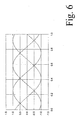
- Figure 6 illustrates light intensity at the different outputs of three way coupler 54 as a function of wavelength.
- PHI 2*pi*L/lambda - m*2*pi, where m in an integer.
- a measured combination of output signals A1, A2, A3 at a given wavelength is sufficient to determine a relative phase of the signals at the inputs of three way coupler.
- Microcontroller 129 is configured to use the output signal from third detector 128c to correct for this. Microcontroller 129 detects steps in the output signal from third detector 128c, quantizes the sizes of these steps and sums the quantized values of the step sizes. The result is an accumulated quantized step size Q.
- microcontroller 129 computes N by counting periods in the signal from at least one of further detectors 56a-c between a reference time point and a measurement time point for which the wavelength difference is computed, and PHI from the amplitudes detected by these detectors at the measurement time point. To this a sum of the spanned quantization levels S is added.
- the sensing device comprises a Bragg grating
- the sensing device comprises a Bragg grating
- other sensing devices with other optical structures such as a ring resonator or a resonant cavity, of which the resonance wavelength must be measured in a calibrated way.
- second filter 126b is a resonant filter
- a three way coupler and three further detectors as in the embodiment of figure 5 may be used, but with a shorter additional optical path.
- This realizes a continuous filter transfer function to any one of the detectors, and it has the additional advantage that the microcomputer can handle mode hops between wavelengths on different sides of a peak in the filter output where the filter has equal response.
- the microcomputer may be configured to use phase values determined from a combination of output signals, as described for figure 5 and use them for the quantization.
- wavelengths may be determined for the time points of a plurality of responses, such as a continuous series of responses during a sweep, in order to determine reflection as a calibrated function of wavelength.
- a program for the computer or microcontroller may be provided on a computer program product, such as a computer readable disc (e.g. magnetic or optical) or a semi-conductor memory or as modulation of a signal.
Landscapes
- Physics & Mathematics (AREA)
- Spectroscopy & Molecular Physics (AREA)
- General Physics & Mathematics (AREA)
- Optical Transform (AREA)
- Measuring Temperature Or Quantity Of Heat (AREA)
Claims (15)
- Dispositif de mesure optique (12), pour mesurer une longueur d'onde d'une réponse provenant d'un dispositif de détection (10), le dispositif de mesure optique (12) comprenant :- un trajet de lumière couplé à une interface (120) destinée à coupler le trajet de lumière au dispositif de détection (10) ;- un filtre optique périodique (126a) ayant une entrée couplée au trajet de lumière, pour échantillonner une lumière qui est envoyée vers ou reçue depuis le dispositif de détection (10) ;- un premier détecteur (128b) couplé à une sortie du filtre optique périodique (126a) ;- un filtre optique à sortie continue (126b) ayant une entrée couplée au trajet de lumière pour échantillonner une lumière qui est envoyée vers ou reçue depuis le dispositif de détection (10), le filtre optique à sortie continue (126b) ayant une amplitude de sortie variable de manière continue en fonction de la longueur d'onde, n'ayant pas de minima ni de maxima locaux dans sa fonction de transfert d'intensité en fonction d'une longueur d'onde en tant que fonction d'une longueur d'onde dans une plage de longueurs d'onde opérationnelle ;- un deuxième détecteur (128c) couplé à une sortie du filtre optique à sortie continue (126b) ;- un troisième détecteur (128a) couplé à la sortie du dispositif de détection (10) ;- un circuit de calcul (129) couplé aux premier, deuxième et troisième détecteurs (128a, b, c), et configuré pour traiter des signaux de sortie provenant des premier, deuxième et troisième détecteurs (128a, b, c) obtenus pendant un balayage de longueur d'onde d'une lumière envoyée à travers le trajet de lumière, en utilisant une quantification des données dérivées du deuxième détecteur (128c) pour identifier des longueurs d'onde associées à des points temporels respectifs au niveau desquels le balayage de longueur d'onde atteint des positions correspondantes dans des périodes respectives du filtre optique périodique (126a), et pour calculer une longueur d'onde associée à la réponse du dispositif de détection (10) à partir des longueurs d'onde identifiées sur la base d'une relation temporelle entre les points temporels respectifs et un point temporel de la réponse du dispositif de détection (10).
- Dispositif de mesure optique selon la revendication 1, dans lequel le circuit de calcul (129) est configuré pour :- utiliser un signal de sortie du premier détecteur (128b) pour détecter les points temporels respectifs, des paires de points temporels successifs définissant des intervalles de temps successifs ;- quantifier les données dérivées du deuxième détecteur (128c),- utiliser les données quantifiées dans des intervalles de temps pour identifier des longueurs d'onde associées aux points temporels respectifs, et- identifier la longueur d'onde associée de la réponse à partir de la longueur d'onde identifiée d'au moins un des points temporels situé au niveau d'un bord de l'intervalle de temps dans lequel la réponse provenant du dispositif de détection (10) a lieu.
- Dispositif de mesure optique selon la revendication 2, dans lequel le circuit de calcul (129) est configuré pour interpoler une longueur d'onde calculée au niveau du point temporel de la réponse en ajoutant une fraction à la longueur d'onde identifiée du au moins un des points temporels situé au niveau du bord de l'intervalle de temps, la fraction étant sélectionnée en proportion d'un rapport entre la distance depuis le point temporel de la réponse jusqu'au au moins un des points temporels, et de la durée de l'intervalle de temps ou d'un intervalle de temps supplémentaire, entre le au moins un des points temporels et un point temporel supplémentaire situé au niveau d'un bord de l'un des intervalles de temps.
- Dispositif de mesure optique selon la revendication 3, dans lequel le circuit de calcul (129) est configuré pour sélectionner le au moins un des points temporels et la période supplémentaire des périodes tributaires d'un gradin détecté dans la sortie du premier et/ou second détecteur, le au moins un des points temporels et la période supplémentaire des périodes étant tous deux sélectionnés sur un côté opposé d'un temps du gradin détecté par rapport au point temporel de la réponse du dispositif de détection (10).
- Dispositif de mesure optique selon l'une quelconque des revendications 1 à 4, dans lequel le circuit de calcul est configuré pour quantifier un signal de sortie du deuxième détecteur (128c) et pour identifier les longueurs d'onde au niveau des points temporels par les valeurs de signal de sortie quantifiées pour les points temporels.
- Dispositif de mesure optique selon l'une quelconque des revendications 1 à 4, dans lequel le circuit de calcul (129) est configuré pour compter les intervalles de temps détectés par le premier détecteur (128b) entre un point temporel de détection de la réponse et un point temporel de référence, pour identifier au moins un gradin dans la sortie du deuxième détecteur (128c) entre le point temporel de détection et le point temporel de référence, pour quantifier le gradin et changer le compte en fonction du nombre de niveaux de quantification dans la valeur quantifiée du gradin.
- Dispositif de mesure optique selon la revendication 6, comprenant :- un filtre optique résonnant (40) ayant une entrée couplée au trajet de lumière, pour échantillonner une lumière qui est envoyée vers ou reçue depuis le dispositif de détection (10), le filtre optique résonnant (40) ayant au moins une longueur d'onde de résonance et, s'il y a plus d'une longueur d'onde de résonance, des longueurs d'onde de résonance espacées d'au moins plusieurs dimensions de période de longueur d'onde du filtre optique périodique (126a) ;- un troisième détecteur (42) couplé à une sortie du filtre optique résonnant (40) ;dans lequel- le circuit de calcul (129) est couplé au troisième détecteur (42) et configuré pour sélectionner le point temporel de référence en réponse à une détection d'un pic de résonance par le troisième détecteur (42).
- Dispositif de mesure optique selon la revendication 5, comprenant :- un filtre optique résonnant (40) ayant une entrée couplée au trajet de lumière, pour échantillonner une lumière qui est envoyée vers ou reçue depuis le dispositif de détection (10), le filtre optique résonnant (40) ayant au moins une longueur d'onde de résonance et, s'il y a plus d'une longueur d'onde de résonance, une longueur d'onde de résonance espacée d'au moins plusieurs dimensions de période de longueur d'onde du filtre optique périodique (126a) ;- un troisième détecteur (42) couplé à une sortie du filtre optique résonnant (40);dans lequel- le circuit de calcul (129) est couplé au troisième détecteur (42), et configuré pour quantifier une différence entre le signal de sortie du deuxième détecteur (128c), au niveau d'un point temporel de référence auquel un pic du signal de sortie du troisième détecteur (42) est détecté, et les points temporels.
- Dispositif de mesure optique selon les revendications 6 ou 7, dans lequel le filtre optique résonnant (40) a une première et une seconde longueur d'onde de résonance, le circuit de calcul étant configuré pour déterminer un premier et un second nombre de gradins dans la sortie du deuxième détecteur (42) entre le point temporel de détection de la réponse et les premier et second points temporels de détection des première et seconde longueurs d'onde de résonance par le troisième détecteur (42) et pour sélectionner le premier ou second point temporel comme point temporel de référence, selon que le premier ou le second nombre est respectivement plus petit.
- Dispositif de mesure optique selon l'une quelconque des revendications précédentes, dans lequel le filtre optique périodique (126a) comprend :- un diviseur (50) ayant une entrée couplée au trajet de lumière,- un premier et un second trajet de lumière supplémentaire de longueurs mutuellement différentes, ayant des entrées couplées aux sorties respectives du diviseur (50), les longueurs déterminant une période du filtre optique périodique ;- un coupleur à N voies (54) ayant des entrées couplées à des sorties du premier et du second trajet de lumière supplémentaire, où N est au moins trois, le coupleur à N voies étant configuré pour émettre une combinaison de lumière à partir du premier et du second trajet de lumière supplémentaire, ayant des déphasages relatifs mutuellement différents sur N sorties,- N détecteurs supplémentaires (56a - c), incluant le premier détecteur, couplés à une sortie respective des sorties du coupleur à N voies (54), et dans lequel- le circuit de calcul (129) est configuré pour déterminer une relation de phase entre la lumière au niveau des sorties du premier et du second trajet de lumière supplémentaire à partir des signaux de sortie des N détecteurs supplémentaires (56a - c), et pour interpoler la longueur d'onde calculée au niveau du point temporel en ajoutant une fraction au compte conformément à un décalage de la relation de phase à partir du début d'une des périodes.
- Dispositif de mesure optique selon l'une quelconque des revendications précédentes pour autant qu'elle dépende de la revendication 6, dans lequel le circuit de calcul (129) est configuré pour déterminer le compte à partir de périodes détectées entre le point temporel de référence et le point temporel de détection et pour ajouter la somme des nombres de niveaux de quantification dans les valeurs quantifiées de plusieurs des gradins détectés entre le point temporel de référence est le point temporel de détection.
- Dispositif de mesure optique selon l'une quelconque des revendications précédentes, comprenant un laser ajustable (122) couplé au trajet de lumière pour fournir cette lumière.
- Dispositif de mesure optique selon l'une quelconque des revendications précédentes comprenant :- une source de lumière pouvant être balayée en longueur d'onde (122) ; et- un détecteur de détection (128a) couplé au trajet de lumière pour recevoir une lumière provenant du dispositif de détection (10),- le circuit de calcul (129) étant couplé au détecteur de détection (128a) et configuré pour déterminer le point temporel de détection à partir d'un temps au niveau duquel le détecteur de détection (128a) détecte un pic ou un creux dans une réponse provenant du dispositif de détection (10) pour la lumière.
- Dispositif de mesure optique selon l'une quelconque des revendications précédentes, comprenant le dispositif de détection (10) couplé à l'interface (120), dans lequel le dispositif de détection (10) est une fibre optique comprenant un réseau de Bragg.
- Procédé de mesure d'une longueur d'onde d'une réponse provenant d'un dispositif de détection, le procédé consistant à :- envoyer une lumière vers le dispositif de détection (10) dans un balayage de longueur d'onde avec une longueur d'onde variant dans le temps ;- détecter une première réponse d'un filtre optique périodique (126a) à un premier échantillon de la lumière en fonction du temps ;- utiliser la première réponse détectée pour détecter des points temporels respectifs au niveau desquels le balayage atteint des positions correspondantes dans des périodes respectives du filtre optique périodique (126a), des paires de points temporels successifs définissant des intervalles de temps ;- détecter une seconde réponse d'un filtre optique à sortie continue (126b) à un second échantillon de la lumière en fonction du temps, le filtre optique à sortie continue (126b) ayant une amplitude de sortie variable en continu en fonction d'une longueur d'onde, n'ayant pas de minima ni de maxima dans sa fonction de transfert d'intensité en fonction de la longueur d'onde en fonction d'une longueur d'onde dans une plage de longueurs d'onde opérationnelles ;- utiliser une quantification de données dérivées de la seconde réponse détectée pour identifier des longueurs d'onde associées aux points temporels respectifs ;- calculer une longueur d'onde associée à la réponse du dispositif de détection (10) à partir des longueurs d'onde identifiées sur la base d'une relation temporelle entre les points temporels respectifs et un point temporel de la réponse du dispositif de détection (10).
Priority Applications (1)
| Application Number | Priority Date | Filing Date | Title |
|---|---|---|---|
| EP11811423.0A EP2656033B8 (fr) | 2010-12-22 | 2011-12-21 | Dispositif de mesure optique |
Applications Claiming Priority (3)
| Application Number | Priority Date | Filing Date | Title |
|---|---|---|---|
| EP10196436A EP2469255A1 (fr) | 2010-12-22 | 2010-12-22 | Dispositif de mesure optique |
| PCT/NL2011/050883 WO2012087136A1 (fr) | 2010-12-22 | 2011-12-21 | Dispositif de mesure optique |
| EP11811423.0A EP2656033B8 (fr) | 2010-12-22 | 2011-12-21 | Dispositif de mesure optique |
Publications (3)
| Publication Number | Publication Date |
|---|---|
| EP2656033A1 EP2656033A1 (fr) | 2013-10-30 |
| EP2656033B1 true EP2656033B1 (fr) | 2015-03-25 |
| EP2656033B8 EP2656033B8 (fr) | 2015-05-20 |
Family
ID=43827341
Family Applications (2)
| Application Number | Title | Priority Date | Filing Date |
|---|---|---|---|
| EP10196436A Withdrawn EP2469255A1 (fr) | 2010-12-22 | 2010-12-22 | Dispositif de mesure optique |
| EP11811423.0A Active EP2656033B8 (fr) | 2010-12-22 | 2011-12-21 | Dispositif de mesure optique |
Family Applications Before (1)
| Application Number | Title | Priority Date | Filing Date |
|---|---|---|---|
| EP10196436A Withdrawn EP2469255A1 (fr) | 2010-12-22 | 2010-12-22 | Dispositif de mesure optique |
Country Status (5)
| Country | Link |
|---|---|
| US (1) | US9651429B2 (fr) |
| EP (2) | EP2469255A1 (fr) |
| JP (1) | JP2014503066A (fr) |
| KR (1) | KR20130131412A (fr) |
| WO (1) | WO2012087136A1 (fr) |
Families Citing this family (2)
| Publication number | Priority date | Publication date | Assignee | Title |
|---|---|---|---|---|
| EP2762847A1 (fr) | 2013-01-31 | 2014-08-06 | Nederlandse Organisatie voor toegepast -natuurwetenschappelijk onderzoek TNO | Système de capteur à fibres optiques et procédé |
| MX362528B (es) | 2013-12-20 | 2019-01-23 | Halliburton Energy Services Inc | Sistema de medicion optica de peliculas finas en paralelo para analizar multianalitos. |
Family Cites Families (9)
| Publication number | Priority date | Publication date | Assignee | Title |
|---|---|---|---|---|
| US5892582A (en) | 1996-10-18 | 1999-04-06 | Micron Optics, Inc. | Fabry Perot/fiber Bragg grating multi-wavelength reference |
| NO307357B1 (no) * | 1997-02-14 | 2000-03-20 | Optoplan As | Anordning for maling av optiske bolgelengder |
| US6498800B1 (en) | 1999-08-10 | 2002-12-24 | Coretek, Inc. | Double etalon optical wavelength reference device |
| NL1021600C2 (nl) | 2002-10-08 | 2004-04-13 | Tno | Meten van een optisch weglengteverschil. |
| GB2399875B (en) * | 2003-03-24 | 2006-02-22 | Tsunami Photonics Ltd | Optical wavelength meter |
| KR100488221B1 (ko) * | 2003-09-08 | 2005-05-10 | 주식회사 파이버프로 | 광섬유 브래그 격자 센서 시스템 |
| US7268884B2 (en) * | 2003-12-23 | 2007-09-11 | Optoplan As | Wavelength reference system for optical measurements |
| US7109471B2 (en) * | 2004-06-04 | 2006-09-19 | Weatherford/Lamb, Inc. | Optical wavelength determination using multiple measurable features |
| US7813046B2 (en) * | 2007-09-14 | 2010-10-12 | Weatherford/Lamb, Inc. | Wavelength monitored and stabilized source |
-
2010
- 2010-12-22 EP EP10196436A patent/EP2469255A1/fr not_active Withdrawn
-
2011
- 2011-12-21 US US13/993,189 patent/US9651429B2/en active Active
- 2011-12-21 EP EP11811423.0A patent/EP2656033B8/fr active Active
- 2011-12-21 JP JP2013546055A patent/JP2014503066A/ja active Pending
- 2011-12-21 KR KR1020137019261A patent/KR20130131412A/ko not_active Application Discontinuation
- 2011-12-21 WO PCT/NL2011/050883 patent/WO2012087136A1/fr active Application Filing
Also Published As
| Publication number | Publication date |
|---|---|
| WO2012087136A1 (fr) | 2012-06-28 |
| US20140300898A1 (en) | 2014-10-09 |
| EP2656033B8 (fr) | 2015-05-20 |
| EP2469255A1 (fr) | 2012-06-27 |
| US9651429B2 (en) | 2017-05-16 |
| JP2014503066A (ja) | 2014-02-06 |
| KR20130131412A (ko) | 2013-12-03 |
| EP2656033A1 (fr) | 2013-10-30 |
Similar Documents
| Publication | Publication Date | Title |
|---|---|---|
| CA2509187C (fr) | Determination des longueurs d'ondes optiques par caracteristiques multiples mesurables | |
| US7411676B2 (en) | Polarization mitigation technique | |
| US7573021B2 (en) | Method and apparatus for multiple scan rate swept wavelength laser-based optical sensor interrogation system with optical path length measurement capability | |
| US7538860B2 (en) | System and method for determination of the reflection wavelength of multiple low-reflectivity bragg gratings in a sensing optical fiber | |
| US8477296B2 (en) | Opto-electronic signal processing methods, systems, and apparatus for optical sensor interrogation | |
| EP2980537B1 (fr) | Réseau de référence multi-crêtes | |
| US8552360B2 (en) | Wavelength sweep control | |
| WO2014186539A1 (fr) | Interrogateur à balayage rapide à multiplexage par répartition dans le temps et à multiplexage par répartition en longueur d'onde | |
| RU102256U1 (ru) | Устройство для измерения параметров физических полей | |
| US11391645B2 (en) | Birefringent multi-peak optical reference element and birefringent sensor system | |
| US8379217B2 (en) | System and method for optical sensor interrogation | |
| EP2656033B1 (fr) | Dispositif de mesure optique | |
| WO2014081295A1 (fr) | Procédé pour l'interrogation d'une pluralité de capteurs optiques, progiciel et unité d'interrogation | |
| RU2512616C2 (ru) | Способ измерения параметров физических полей и устройство для его осуществления | |
| US20150362386A1 (en) | Fiber optic sensor system and method | |
| RU92180U1 (ru) | Устройство для измерения параметров физических полей | |
| RU191082U1 (ru) | Самокалибрующийся анализатор сигналов волоконно-оптических датчиков на основе волоконных брэгговских решеток |
Legal Events
| Date | Code | Title | Description |
|---|---|---|---|
| PUAI | Public reference made under article 153(3) epc to a published international application that has entered the european phase |
Free format text: ORIGINAL CODE: 0009012 |
|
| 17P | Request for examination filed |
Effective date: 20130719 |
|
| AK | Designated contracting states |
Kind code of ref document: A1 Designated state(s): AL AT BE BG CH CY CZ DE DK EE ES FI FR GB GR HR HU IE IS IT LI LT LU LV MC MK MT NL NO PL PT RO RS SE SI SK SM TR |
|
| DAX | Request for extension of the european patent (deleted) | ||
| GRAP | Despatch of communication of intention to grant a patent |
Free format text: ORIGINAL CODE: EPIDOSNIGR1 |
|
| INTG | Intention to grant announced |
Effective date: 20140519 |
|
| GRAP | Despatch of communication of intention to grant a patent |
Free format text: ORIGINAL CODE: EPIDOSNIGR1 |
|
| INTG | Intention to grant announced |
Effective date: 20141016 |
|
| GRAS | Grant fee paid |
Free format text: ORIGINAL CODE: EPIDOSNIGR3 |
|
| GRAA | (expected) grant |
Free format text: ORIGINAL CODE: 0009210 |
|
| AK | Designated contracting states |
Kind code of ref document: B1 Designated state(s): AL AT BE BG CH CY CZ DE DK EE ES FI FR GB GR HR HU IE IS IT LI LT LU LV MC MK MT NL NO PL PT RO RS SE SI SK SM TR |
|
| REG | Reference to a national code |
Ref country code: GB Ref legal event code: FG4D |
|
| REG | Reference to a national code |
Ref country code: CH Ref legal event code: EP |
|
| RAP2 | Party data changed (patent owner data changed or rights of a patent transferred) |
Owner name: NEDERLANDSE ORGANISATIE VOOR TOEGEPAST- NATUURWETE |
|
| REG | Reference to a national code |
Ref country code: IE Ref legal event code: FG4D |
|
| REG | Reference to a national code |
Ref country code: DE Ref legal event code: R096 Ref document number: 602011015118 Country of ref document: DE Effective date: 20150507 |
|
| REG | Reference to a national code |
Ref country code: AT Ref legal event code: REF Ref document number: 718144 Country of ref document: AT Kind code of ref document: T Effective date: 20150515 |
|
| REG | Reference to a national code |
Ref country code: NL Ref legal event code: T3 |
|
| PG25 | Lapsed in a contracting state [announced via postgrant information from national office to epo] |
Ref country code: SE Free format text: LAPSE BECAUSE OF FAILURE TO SUBMIT A TRANSLATION OF THE DESCRIPTION OR TO PAY THE FEE WITHIN THE PRESCRIBED TIME-LIMIT Effective date: 20150325 Ref country code: LT Free format text: LAPSE BECAUSE OF FAILURE TO SUBMIT A TRANSLATION OF THE DESCRIPTION OR TO PAY THE FEE WITHIN THE PRESCRIBED TIME-LIMIT Effective date: 20150325 Ref country code: HR Free format text: LAPSE BECAUSE OF FAILURE TO SUBMIT A TRANSLATION OF THE DESCRIPTION OR TO PAY THE FEE WITHIN THE PRESCRIBED TIME-LIMIT Effective date: 20150325 Ref country code: FI Free format text: LAPSE BECAUSE OF FAILURE TO SUBMIT A TRANSLATION OF THE DESCRIPTION OR TO PAY THE FEE WITHIN THE PRESCRIBED TIME-LIMIT Effective date: 20150325 |
|
| REG | Reference to a national code |
Ref country code: AT Ref legal event code: MK05 Ref document number: 718144 Country of ref document: AT Kind code of ref document: T Effective date: 20150325 |
|
| REG | Reference to a national code |
Ref country code: LT Ref legal event code: MG4D |
|
| PG25 | Lapsed in a contracting state [announced via postgrant information from national office to epo] |
Ref country code: RS Free format text: LAPSE BECAUSE OF FAILURE TO SUBMIT A TRANSLATION OF THE DESCRIPTION OR TO PAY THE FEE WITHIN THE PRESCRIBED TIME-LIMIT Effective date: 20150325 Ref country code: LV Free format text: LAPSE BECAUSE OF FAILURE TO SUBMIT A TRANSLATION OF THE DESCRIPTION OR TO PAY THE FEE WITHIN THE PRESCRIBED TIME-LIMIT Effective date: 20150325 Ref country code: GR Free format text: LAPSE BECAUSE OF FAILURE TO SUBMIT A TRANSLATION OF THE DESCRIPTION OR TO PAY THE FEE WITHIN THE PRESCRIBED TIME-LIMIT Effective date: 20150626 |
|
| PG25 | Lapsed in a contracting state [announced via postgrant information from national office to epo] |
Ref country code: SK Free format text: LAPSE BECAUSE OF FAILURE TO SUBMIT A TRANSLATION OF THE DESCRIPTION OR TO PAY THE FEE WITHIN THE PRESCRIBED TIME-LIMIT Effective date: 20150325 Ref country code: PT Free format text: LAPSE BECAUSE OF FAILURE TO SUBMIT A TRANSLATION OF THE DESCRIPTION OR TO PAY THE FEE WITHIN THE PRESCRIBED TIME-LIMIT Effective date: 20150727 Ref country code: ES Free format text: LAPSE BECAUSE OF FAILURE TO SUBMIT A TRANSLATION OF THE DESCRIPTION OR TO PAY THE FEE WITHIN THE PRESCRIBED TIME-LIMIT Effective date: 20150325 Ref country code: RO Free format text: LAPSE BECAUSE OF FAILURE TO SUBMIT A TRANSLATION OF THE DESCRIPTION OR TO PAY THE FEE WITHIN THE PRESCRIBED TIME-LIMIT Effective date: 20150325 Ref country code: CZ Free format text: LAPSE BECAUSE OF FAILURE TO SUBMIT A TRANSLATION OF THE DESCRIPTION OR TO PAY THE FEE WITHIN THE PRESCRIBED TIME-LIMIT Effective date: 20150325 Ref country code: EE Free format text: LAPSE BECAUSE OF FAILURE TO SUBMIT A TRANSLATION OF THE DESCRIPTION OR TO PAY THE FEE WITHIN THE PRESCRIBED TIME-LIMIT Effective date: 20150325 |
|
| PG25 | Lapsed in a contracting state [announced via postgrant information from national office to epo] |
Ref country code: IS Free format text: LAPSE BECAUSE OF FAILURE TO SUBMIT A TRANSLATION OF THE DESCRIPTION OR TO PAY THE FEE WITHIN THE PRESCRIBED TIME-LIMIT Effective date: 20150725 Ref country code: AT Free format text: LAPSE BECAUSE OF FAILURE TO SUBMIT A TRANSLATION OF THE DESCRIPTION OR TO PAY THE FEE WITHIN THE PRESCRIBED TIME-LIMIT Effective date: 20150325 Ref country code: PL Free format text: LAPSE BECAUSE OF FAILURE TO SUBMIT A TRANSLATION OF THE DESCRIPTION OR TO PAY THE FEE WITHIN THE PRESCRIBED TIME-LIMIT Effective date: 20150325 |
|
| REG | Reference to a national code |
Ref country code: FR Ref legal event code: PLFP Year of fee payment: 5 |
|
| REG | Reference to a national code |
Ref country code: DE Ref legal event code: R097 Ref document number: 602011015118 Country of ref document: DE |
|
| PG25 | Lapsed in a contracting state [announced via postgrant information from national office to epo] |
Ref country code: DK Free format text: LAPSE BECAUSE OF FAILURE TO SUBMIT A TRANSLATION OF THE DESCRIPTION OR TO PAY THE FEE WITHIN THE PRESCRIBED TIME-LIMIT Effective date: 20150325 |
|
| PLBE | No opposition filed within time limit |
Free format text: ORIGINAL CODE: 0009261 |
|
| STAA | Information on the status of an ep patent application or granted ep patent |
Free format text: STATUS: NO OPPOSITION FILED WITHIN TIME LIMIT |
|
| 26N | No opposition filed |
Effective date: 20160105 |
|
| PG25 | Lapsed in a contracting state [announced via postgrant information from national office to epo] |
Ref country code: IT Free format text: LAPSE BECAUSE OF FAILURE TO SUBMIT A TRANSLATION OF THE DESCRIPTION OR TO PAY THE FEE WITHIN THE PRESCRIBED TIME-LIMIT Effective date: 20150325 |
|
| PG25 | Lapsed in a contracting state [announced via postgrant information from national office to epo] |
Ref country code: SI Free format text: LAPSE BECAUSE OF FAILURE TO SUBMIT A TRANSLATION OF THE DESCRIPTION OR TO PAY THE FEE WITHIN THE PRESCRIBED TIME-LIMIT Effective date: 20150325 Ref country code: BE Free format text: LAPSE BECAUSE OF NON-PAYMENT OF DUE FEES Effective date: 20151231 |
|
| PG25 | Lapsed in a contracting state [announced via postgrant information from national office to epo] |
Ref country code: MC Free format text: LAPSE BECAUSE OF FAILURE TO SUBMIT A TRANSLATION OF THE DESCRIPTION OR TO PAY THE FEE WITHIN THE PRESCRIBED TIME-LIMIT Effective date: 20150325 Ref country code: LU Free format text: LAPSE BECAUSE OF FAILURE TO SUBMIT A TRANSLATION OF THE DESCRIPTION OR TO PAY THE FEE WITHIN THE PRESCRIBED TIME-LIMIT Effective date: 20151221 |
|
| REG | Reference to a national code |
Ref country code: CH Ref legal event code: PL |
|
| PG25 | Lapsed in a contracting state [announced via postgrant information from national office to epo] |
Ref country code: BE Free format text: LAPSE BECAUSE OF FAILURE TO SUBMIT A TRANSLATION OF THE DESCRIPTION OR TO PAY THE FEE WITHIN THE PRESCRIBED TIME-LIMIT Effective date: 20150325 |
|
| REG | Reference to a national code |
Ref country code: IE Ref legal event code: MM4A |
|
| PG25 | Lapsed in a contracting state [announced via postgrant information from national office to epo] |
Ref country code: CH Free format text: LAPSE BECAUSE OF NON-PAYMENT OF DUE FEES Effective date: 20151231 Ref country code: LI Free format text: LAPSE BECAUSE OF NON-PAYMENT OF DUE FEES Effective date: 20151231 Ref country code: IE Free format text: LAPSE BECAUSE OF NON-PAYMENT OF DUE FEES Effective date: 20151221 |
|
| REG | Reference to a national code |
Ref country code: FR Ref legal event code: PLFP Year of fee payment: 6 |
|
| PG25 | Lapsed in a contracting state [announced via postgrant information from national office to epo] |
Ref country code: HU Free format text: LAPSE BECAUSE OF FAILURE TO SUBMIT A TRANSLATION OF THE DESCRIPTION OR TO PAY THE FEE WITHIN THE PRESCRIBED TIME-LIMIT; INVALID AB INITIO Effective date: 20111221 Ref country code: SM Free format text: LAPSE BECAUSE OF FAILURE TO SUBMIT A TRANSLATION OF THE DESCRIPTION OR TO PAY THE FEE WITHIN THE PRESCRIBED TIME-LIMIT Effective date: 20150325 Ref country code: BG Free format text: LAPSE BECAUSE OF FAILURE TO SUBMIT A TRANSLATION OF THE DESCRIPTION OR TO PAY THE FEE WITHIN THE PRESCRIBED TIME-LIMIT Effective date: 20150325 Ref country code: NO Free format text: LAPSE BECAUSE OF FAILURE TO SUBMIT A TRANSLATION OF THE DESCRIPTION OR TO PAY THE FEE WITHIN THE PRESCRIBED TIME-LIMIT Effective date: 20150625 |
|
| PG25 | Lapsed in a contracting state [announced via postgrant information from national office to epo] |
Ref country code: CY Free format text: LAPSE BECAUSE OF FAILURE TO SUBMIT A TRANSLATION OF THE DESCRIPTION OR TO PAY THE FEE WITHIN THE PRESCRIBED TIME-LIMIT Effective date: 20150325 |
|
| PG25 | Lapsed in a contracting state [announced via postgrant information from national office to epo] |
Ref country code: MT Free format text: LAPSE BECAUSE OF FAILURE TO SUBMIT A TRANSLATION OF THE DESCRIPTION OR TO PAY THE FEE WITHIN THE PRESCRIBED TIME-LIMIT Effective date: 20150325 |
|
| REG | Reference to a national code |
Ref country code: FR Ref legal event code: PLFP Year of fee payment: 7 |
|
| PG25 | Lapsed in a contracting state [announced via postgrant information from national office to epo] |
Ref country code: MK Free format text: LAPSE BECAUSE OF FAILURE TO SUBMIT A TRANSLATION OF THE DESCRIPTION OR TO PAY THE FEE WITHIN THE PRESCRIBED TIME-LIMIT Effective date: 20150325 |
|
| PG25 | Lapsed in a contracting state [announced via postgrant information from national office to epo] |
Ref country code: TR Free format text: LAPSE BECAUSE OF FAILURE TO SUBMIT A TRANSLATION OF THE DESCRIPTION OR TO PAY THE FEE WITHIN THE PRESCRIBED TIME-LIMIT Effective date: 20150325 Ref country code: AL Free format text: LAPSE BECAUSE OF FAILURE TO SUBMIT A TRANSLATION OF THE DESCRIPTION OR TO PAY THE FEE WITHIN THE PRESCRIBED TIME-LIMIT Effective date: 20150325 |
|
| P01 | Opt-out of the competence of the unified patent court (upc) registered |
Effective date: 20230522 |
|
| PGFP | Annual fee paid to national office [announced via postgrant information from national office to epo] |
Ref country code: GB Payment date: 20231220 Year of fee payment: 13 |
|
| PGFP | Annual fee paid to national office [announced via postgrant information from national office to epo] |
Ref country code: NL Payment date: 20231220 Year of fee payment: 13 Ref country code: FR Payment date: 20231221 Year of fee payment: 13 Ref country code: DE Payment date: 20231214 Year of fee payment: 13 |