EP2655967B1 - Gas fired radiation emitter with embossed screen - Google Patents
Gas fired radiation emitter with embossed screen Download PDFInfo
- Publication number
- EP2655967B1 EP2655967B1 EP11793459.6A EP11793459A EP2655967B1 EP 2655967 B1 EP2655967 B1 EP 2655967B1 EP 11793459 A EP11793459 A EP 11793459A EP 2655967 B1 EP2655967 B1 EP 2655967B1
- Authority
- EP
- European Patent Office
- Prior art keywords
- burner plate
- radiant screen
- gas fired
- screen
- radiant
- Prior art date
- Legal status (The legal status is an assumption and is not a legal conclusion. Google has not performed a legal analysis and makes no representation as to the accuracy of the status listed.)
- Not-in-force
Links
Images

Classifications
-
- F—MECHANICAL ENGINEERING; LIGHTING; HEATING; WEAPONS; BLASTING
- F23—COMBUSTION APPARATUS; COMBUSTION PROCESSES
- F23D—BURNERS
- F23D14/00—Burners for combustion of a gas, e.g. of a gas stored under pressure as a liquid
- F23D14/12—Radiant burners
- F23D14/14—Radiant burners using screens or perforated plates
- F23D14/145—Radiant burners using screens or perforated plates combustion being stabilised at a screen or a perforated plate
-
- F—MECHANICAL ENGINEERING; LIGHTING; HEATING; WEAPONS; BLASTING
- F23—COMBUSTION APPARATUS; COMBUSTION PROCESSES
- F23D—BURNERS
- F23D14/00—Burners for combustion of a gas, e.g. of a gas stored under pressure as a liquid
- F23D14/12—Radiant burners
- F23D14/16—Radiant burners using permeable blocks
-
- F—MECHANICAL ENGINEERING; LIGHTING; HEATING; WEAPONS; BLASTING
- F23—COMBUSTION APPARATUS; COMBUSTION PROCESSES
- F23D—BURNERS
- F23D14/00—Burners for combustion of a gas, e.g. of a gas stored under pressure as a liquid
- F23D14/12—Radiant burners
- F23D14/14—Radiant burners using screens or perforated plates
- F23D14/147—Radiant burners using screens or perforated plates with perforated plates as radiation intensifying means
-
- F—MECHANICAL ENGINEERING; LIGHTING; HEATING; WEAPONS; BLASTING
- F23—COMBUSTION APPARATUS; COMBUSTION PROCESSES
- F23D—BURNERS
- F23D14/00—Burners for combustion of a gas, e.g. of a gas stored under pressure as a liquid
- F23D14/12—Radiant burners
- F23D14/14—Radiant burners using screens or perforated plates
- F23D14/149—Radiant burners using screens or perforated plates with wires, threads or gauzes as radiation intensifying means
-
- F—MECHANICAL ENGINEERING; LIGHTING; HEATING; WEAPONS; BLASTING
- F23—COMBUSTION APPARATUS; COMBUSTION PROCESSES
- F23D—BURNERS
- F23D2203/00—Gaseous fuel burners
- F23D2203/10—Flame diffusing means
- F23D2203/103—Flame diffusing means using screens
-
- F—MECHANICAL ENGINEERING; LIGHTING; HEATING; WEAPONS; BLASTING
- F23—COMBUSTION APPARATUS; COMBUSTION PROCESSES
- F23D—BURNERS
- F23D2203/00—Gaseous fuel burners
- F23D2203/10—Flame diffusing means
- F23D2203/105—Porous plates
Definitions
- the invention relates to the technical field of gas fired radiation emitters having a combustion surface and a radiation screen (or radiant screen) positioned in front of the combustion surface.
- Gas fired infrared radiation emitters are widely used in the pulp and paper industry for the drying of coatings on moving cellulosic webs. These emitters are well known; thus, for example, one such emitter is described in U.S. Pat. No. 5,820,361 .
- the prior art gas fired infrared radiation emitters often contain a radiating (reverberating, radiant) screen (or "grating") which increases the radiant power output of the emitter while simultaneously protecting the primary radiating surface from contamination.
- a radiating (reverberating, radiant) screen or "grating”
- An example of an emitter with a removable grating is disclosed in U.S. Pat. No. 5,820,361 .
- Another related infrared radiation emitter is known from EP 2 716 979 , which is a prior art document in the sense of Article 54(3) EPC.
- Radiant burners comprising a radiant burner plate and a screen are also known from e.g. US4799879 or EP0539278 .
- US 6,514,071 describes a gas-fired infrared radiation emitter comprising a burner surface; a radiant screen and a frame structure on the screen to removably position and to strengthen the screen.
- US 5,989,013 describes a porous mat gas fired radiant burner panels utilizing improved reverberating screens. The purpose of these screens is to boost the overall radiant output of the burner relative to a burner using no screen and the same fuel-air flow rates.
- the reverberating screen is fabricated from ceramic composite material, which can withstand higher operating temperatures than its metallic equivalent.
- the reverberating screen is corrugated. The corrugations add stiffness which helps to resist creep and thermally induced distortions due to temperature or thermal expansion coefficient differences. As an added benefit, it has been discovered that the corrugations further increase the radiant efficiency of the burner.
- the reverberating screen is both corrugated and made from ceramic composite material.
- US 3,122,197 discloses a radiant burner comprising a casting defining a cavity, one side of the casting having an opening formed therein, the remaining surface of the side defining a flat rim surrounding the opening, a venture tube connected, in fluid flow relation, to the interior of said cavity to convey gas and air thereto.
- a first flat, perforated member covering said opening a second, flexible, perforated, combustion-sustaining member including a central portion which overlies the opening and the corresponding portion of the first member.
- the central portion is fabricated to provide a number of parallel, U-shaped formations which cover said opening. The biggest portion of some of the U-shaped formations having substantially line contact with the first member.
- the bight portions of the remaining U-shaped formations of the central portion are tangent to a plane spaced from, and parallel to, the plan of the first member.
- the distance between the planes is greater than the combined thickness of the first and second members.
- the disclosure includes means for detachably clamping the peripheries of both of the screens to the rim.
- US 3,439,996 for instance, relates to radiant gas burners constituted of assembled heat-insulating perforated refractory tiles or blocks.
- the tiles are joined side by side with a refractory jointing compound or tile cement which, upon hardening, bonds the tile together and holds them in assembled relationship much as bricks are bonded together by mortar.
- a known problem of radiant gas burners relates to the efficiency and effectiveness of the radiant screens.
- An aspect of the invention provides a gas fired infrared radiation emitter comprising a burner plate which is acting as combustion surface; and a radiant screen positioned at the combustion side of the burner plate.
- the radiant screen is embossed providing at the embossment different distances between the burner plate and the radiant screen compared to the distance between the burner plate and the radiant screen at the non-embossed part of the radiant screen.
- the radiant screen is a metal grid or a woven wire mesh.
- embossment is meant a deformation of a surface out of the plane along more than one linear direction in the plane.
- An embossment differs from an undulation in that in an undulation the deformation of a surface out of the plane is only along one linear direction in the plane, e.g. in the form of waves.
- the embossment or embossments present in the radiant screen increase the mechanical resistance of the screen, e.g. against the thermal deformations. Therefore, it allows the economy of a rigidifying means such as a metal cross.
- the burner plate which acts as combustion surface is comprising a ceramic plate or ceramic plates, e.g. a perforated ceramic tile or tiles.
- the different distances at some of the embossments are closer distances. In further specific embodiments, the different distances at all of the embossments are closer distances.
- the different distances at at least some of the embossments are larger distances.
- the embossments that have larger differences are positioned above locations of the burner plate that have higher temperatures than other zones, e.g. in the middle of the burner plate, or in the middle of tiles that are comprised in the burner plate. This has the benefit that the local higher temperature of the burner plate is compensated, resulting in more even temperature over the surface of the radiant screen and in a longer lifetime of the radiant screen.
- the burner plate comprises one perforated tile as combustion surface.
- An alternative aspect of the invention provides a gas fired infrared radiation emitter in which the burner plate comprises at least two perforated tiles. The perforated tiles are placed next to each other in one or two directions to form the burner plate.
- the radiant screen is embossed at at least one junction between two perforated tiles of the burner plate.
- the embossment at at least one junction between two perforated tiles of the burner plate has closer distances, which presents an additional benefit.
- the junction between two perforated tiles is the coldest point of the burner plate; as a consequence, the part of the radiant screen located above this junction is at a lower temperature than the average temperature of the radiant screen, resulting in less infrared radiation energy emitted by the radiant screen.
- the embossment or embossments according to this more specific embodiment of the invention reduce locally the distance between the radiant screen and the burner plate.
- the radiant screen receives more convective heat resulting in a higher temperature and more infrared radiation energy sent out.
- the radiant screen radiates also energy back to the burner plate, relatively more energy is radiated back to the burner surface at the closer distance between burner surface and the screen.
- the burner surface temperature rises locally.
- the radiation energy is more uniform over the surface of the gas fired infrared radiation burner and the efficiency of the gas fired infrared radiation burner is increased.
- embossment or embossments at the perforated tile junctions with closer distances as in the specific embodiment has an additional benefit.
- the closer distance between embossment and the combustion surface does not lead to a higher temperature of the radiant screen as would be the case with undulations or embossments having closer distances above the combustion surface itself; which would lead to a higher thermal load at the embossments or undulations of the radiant screen due to the close position of the screen to the combustion surface.
- the radiant screen is embossed at all the junctions between perforated tiles of the burner plate.
- the burner plate comprises two perforated tiles positioned side by side, and the radiant screen is embossed at the junction between the two perforated tiles.
- the different perforations - and hence the combustion spots - in the burner plate are all in the same plane.
- the burner plate has multiple levels of combustion surface spread over the surface of the burner plate. This embodiment provides the further advantage that noise levels of the gas fired radiation emitter are reduced.
- the burner plate has two levels of combustion surface. In an even more preferred embodiment, the different levels of combustion surface are evenly distributed over the burner plate.
- a cross section of the embossment has a V - shape. In yet another embodiment of the invention, a cross section of the embossment has a U - shape.
- the radiant screen is (in addition to the screen being embossed) bent at at least one of the end sides of the radiant screen. It is a benefit of this embodiment that an additional rigidifying effect of the radiant screen is obtained.
- Another aspect of the invention is the use of the gas fired radiation emitter according to the invention.
- the radiant screen is fabricated from highly heat and corrosion resistant steel grades, such as high level stainless steel grades such as FeCrAl or FeCrAlMo alloy steel grades, or such as chrome/nickel steel grades (e.g. X10CrNiSiN21-11, X9CrNiSiNCe21-11-2 or X6CrNiSiNCe19-10; steel compositions according to EN-standards).
- high level stainless steel grades such as FeCrAl or FeCrAlMo alloy steel grades, or such as chrome/nickel steel grades (e.g. X10CrNiSiN21-11, X9CrNiSiNCe21-11-2 or X6CrNiSiNCe19-10; steel compositions according to EN-standards).
- the radiant screen is produced from highly heat resistant materials such as ceramics, especially aluminum or zirconium oxide, aluminum titanate, silicon oxide, corundum or mullite, silicon carbide, silicon nitride or metal infiltrated ceramics, such as silicon-infiltrated silicon carbide.
- the radiant screen can also be fabricated from heat-resistant materials of other nature such as e.g. materials which contain more than 50% by weight of a metal silicide, such as molybdenum disilicide (MoSi2) or tungsten disilicide (WSi2).
- the radiant burner plate comprises perforated tiles of a ceramic material with high temperature resistance, and excellent mechanical and thermodynamic properties such as e.g. cordierite or zirconia; partially stabilized zirconia (PSZ), alumina, silicon carbides or other high level technical ceramics.
- a ceramic material with high temperature resistance and excellent mechanical and thermodynamic properties
- PSZ partially stabilized zirconia
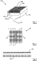
- a gas fired radiation emitter 100 in figure 1 comprises a body 110, an inlet 120 for gas and air and a gas distribution plate 130 and burner plate 140.
- Radiant screen 160 has an embossment 180.
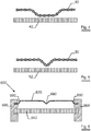
- Figure 2 shows a top view of a radiant screen 20 with embossment 22 according to the invention.
- Figure 3 shows the cross section of figure 2 at line I-I'.
- the radiant screen 30 is straight and is at a distance from the burner plate 32.
- Figure 4 shows the cross section of figure 2 at line II-II'.
- the radiant screen 40 is embossed creating at the embossment a lower distance to the burner plate 42.
- Figure 5 shows the cross section of figure 2 at line III-III'.
- the radiant screen 50 is embossed creating at the embossment a lower distance to the burner plate 52.
- Figure 6 shows an alternative embodiment of a gas fired infrared radiation emitter 600 according to the invention.
- Radiant screen 620 and burner plate 640 are fixed in a housing 660.
- Radiant screen 620 is embossed in the middle 680 and bent at the fixations 690 with the housing 660.
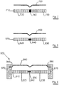
- Figure 7 shows an embodiment of the invention in which the burner plate 710 comprises two perforated tiles 720 and 730.
- the two perforated tiles 720 and 730 are joined side by side with a refractory jointing compound or tile cement 740.
- the radiant screen 750 is embossed at the location of the joint 740 between the two tiles 720 and 730.
- Figure 8 shows an embodiment of the invention in which the burner plate 810 comprises two perforated tiles 820 and 830. Two perforated tiles 820 and 830 are joined side by side via an insert 840.
- the radiant screen 850 is embossed at the location of the joint 840 between the two tiles 820 and 830.
- the insert 840 creates a flexible joint between the two tiles 820 and 830.
- FIG 9 shows an alternative embodiment of a gas fired infrared radiation emitter 900 according to the invention.
- Burner plate 910 comprises two perforated tiles 920 and 930. The two perforated tiles 920 and 930 are joined side by side via an insert 940 forming a junction 950.
- Radiant screen 960 and burner plate 910 are fixed in a housing 970. Radiant screen 960 is embossed above the junction 950 between the two perforated tiles 920 and 930. The radiant screen 960 is bent at the fixations 980 with housing 970.
- Figure 10 shows a schematic representation of a burner plate 1000 with two different levels of the combustion surface.
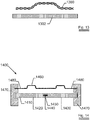
- Figure 11 shows a schematic representation of an alternative cross section of the embossment along line III-III' of figure 2 , in which the cross section of the embossment is shown as 1100.
- Figure 12 shows a schematic representation of a yet another alternative cross section of the embossment along line III-III' of figure 2 , in which the cross section of the embossment is shown as 1200.
- Figure 13 shows the cross section of another embodiment of the invention.
- the radiant screen 1300 is embossed at a central zone of the burner plate creating at the embossment a larger distance to the burner plate 1302.
- FIG 14 shows yet an alternative embodiment of a gas fired infrared radiation emitter 1400 according to the invention.
- Burner plate 1410 comprises two perforated tiles 1420 and 1430. The two perforated tiles 1420 and 1430 are joined side by side via an insert 1440 forming a junction 1450.
- Radiant screen 1460 and burner plate 1410 are fixed in a housing 1470.
- Radiant screen 1460 is embossed in the central zones of the perforated tiles 1420 and 1430, providing in the embossments larger distances to the burner plate.
- the radiant screen 1460 is fixed at 1480 into housing 1470.
- the embossment in the radiant screen ends along its longest length at a distance in the range of 4 to 30 mm from the side of the radiant screen. In a more preferred embodiment, the embossment in the radiant screen ends along its longest length at a distance in the range of 5 to 20 mm from the side of the radiant screen. In an even more preferred embodiment, the embossment in the radiant screen ends along its longest length at a distance in the range of 5 to 10 mm from the side of the radiant screen.
- the embossment is in a V-shape
- the legs of the "V” have an included angle between 50 and 130 degrees.
- the legs of the "V” have an included angle between 60 and 120 degrees.
- the legs of the "V” have an included angle between 75 and 105 degrees.
- the distance of the flat portion of the radiant screen to the combustion surface is within the range of 5 - 20 mm. In a more preferred embodiment, the distance of the flat portion of the radiant screen to the combustion surface is within the range of 7 - 17 mm. In another embodiment of the invention, the distance of the flat portion of the radiant screen to the combustion surface is within the range of 10 - 15 mm.
- the depth of an embossment with closer distance to the flat portion of the radiant screen is at its deepest point in the range of 6 to 15 mm. In a preferred embodiment, the depth of an embossment with closer distance to the flat portion of the radiant screen is at its deepest point in the range of 6 to 12 mm. In a more preferred embodiment, the depth of an embossment with closer distance to the flat portion of the radiant screen is at its deepest point in the range of 7 to 10 mm.
- the gap between the deepest point of an embossment with closer distance and the combustion surface is in the range of 2 - 8 mm. In a preferred embodiment, the gap between the deepest point of an embossment with closer distance and the combustion surface is in the range of 2 - 5 mm.
Landscapes
- Engineering & Computer Science (AREA)
- Chemical & Material Sciences (AREA)
- Combustion & Propulsion (AREA)
- Mechanical Engineering (AREA)
- General Engineering & Computer Science (AREA)
- Gas Burners (AREA)
Description
- The invention relates to the technical field of gas fired radiation emitters having a combustion surface and a radiation screen (or radiant screen) positioned in front of the combustion surface.
- Gas fired infrared radiation emitters are widely used in the pulp and paper industry for the drying of coatings on moving cellulosic webs. These emitters are well known; thus, for example, one such emitter is described in
U.S. Pat. No. 5,820,361 . - The prior art gas fired infrared radiation emitters often contain a radiating (reverberating, radiant) screen (or "grating") which increases the radiant power output of the emitter while simultaneously protecting the primary radiating surface from contamination. An example of an emitter with a removable grating is disclosed in
U.S. Pat. No. 5,820,361 . Another related infrared radiation emitter is known fromEP 2 716 979 , which is a prior art document in the sense of Article 54(3) EPC. -
- It is known in the field to use a reinforcing cross above the radiant screen in or to strengthen the radiant screen and increase its lifetime.
-
US 6,514,071 describes a gas-fired infrared radiation emitter comprising a burner surface; a radiant screen and a frame structure on the screen to removably position and to strengthen the screen. -
US 5,989,013 describes a porous mat gas fired radiant burner panels utilizing improved reverberating screens. The purpose of these screens is to boost the overall radiant output of the burner relative to a burner using no screen and the same fuel-air flow rates. In one embodiment, the reverberating screen is fabricated from ceramic composite material, which can withstand higher operating temperatures than its metallic equivalent. In another embodiment ofUS 5,989,013 the reverberating screen is corrugated. The corrugations add stiffness which helps to resist creep and thermally induced distortions due to temperature or thermal expansion coefficient differences. As an added benefit, it has been discovered that the corrugations further increase the radiant efficiency of the burner. In a preferred embodiment, the reverberating screen is both corrugated and made from ceramic composite material. -
US 3,122,197 discloses a radiant burner comprising a casting defining a cavity, one side of the casting having an opening formed therein, the remaining surface of the side defining a flat rim surrounding the opening, a venture tube connected, in fluid flow relation, to the interior of said cavity to convey gas and air thereto. A first flat, perforated member covering said opening, a second, flexible, perforated, combustion-sustaining member including a central portion which overlies the opening and the corresponding portion of the first member. The central portion is fabricated to provide a number of parallel, U-shaped formations which cover said opening. The biggest portion of some of the U-shaped formations having substantially line contact with the first member. The bight portions of the remaining U-shaped formations of the central portion are tangent to a plane spaced from, and parallel to, the plan of the first member. The distance between the planes is greater than the combined thickness of the first and second members. The disclosure includes means for detachably clamping the peripheries of both of the screens to the rim. - It has been common practice in radiant gas burners to join together a number of perforated tiles (e.g. perforated ceramic tiles) arranged in rows or a square to provide a unitary burner plate. Flexible joints between individual perforated tiles are known as well as rigid joints.
-
US 3,439,996 for instance, relates to radiant gas burners constituted of assembled heat-insulating perforated refractory tiles or blocks. The tiles are joined side by side with a refractory jointing compound or tile cement which, upon hardening, bonds the tile together and holds them in assembled relationship much as bricks are bonded together by mortar. - A known problem of radiant gas burners relates to the efficiency and effectiveness of the radiant screens.
- It is an objective of the invention to improve the performance of gas fired radiation emitters.
- An aspect of the invention provides a gas fired infrared radiation emitter comprising a burner plate which is acting as combustion surface; and a radiant screen positioned at the combustion side of the burner plate. The radiant screen is embossed providing at the embossment different distances between the burner plate and the radiant screen compared to the distance between the burner plate and the radiant screen at the non-embossed part of the radiant screen. The radiant screen is a metal grid or a woven wire mesh.
- With embossment is meant a deformation of a surface out of the plane along more than one linear direction in the plane. An embossment differs from an undulation in that in an undulation the deformation of a surface out of the plane is only along one linear direction in the plane, e.g. in the form of waves.
- It is a benefit of the invention that the embossment or embossments present in the radiant screen increase the mechanical resistance of the screen, e.g. against the thermal deformations. Therefore, it allows the economy of a rigidifying means such as a metal cross.
- Preferably, the burner plate which acts as combustion surface is comprising a ceramic plate or ceramic plates, e.g. a perforated ceramic tile or tiles.
- In specific embodiments, the different distances at some of the embossments are closer distances. In further specific embodiments, the different distances at all of the embossments are closer distances.
- In other specific embodiments, the different distances at at least some of the embossments are larger distances. Preferably, the embossments that have larger differences are positioned above locations of the burner plate that have higher temperatures than other zones, e.g. in the middle of the burner plate, or in the middle of tiles that are comprised in the burner plate. This has the benefit that the local higher temperature of the burner plate is compensated, resulting in more even temperature over the surface of the radiant screen and in a longer lifetime of the radiant screen.
- In another embodiment of the invention, the burner plate comprises one perforated tile as combustion surface. An alternative aspect of the invention provides a gas fired infrared radiation emitter in which the burner plate comprises at least two perforated tiles. The perforated tiles are placed next to each other in one or two directions to form the burner plate.
- In yet another embodiment, the radiant screen is embossed at at least one junction between two perforated tiles of the burner plate. In a more specific embodiment the embossment at at least one junction between two perforated tiles of the burner plate has closer distances, which presents an additional benefit. In burners according to the state of the art the junction between two perforated tiles is the coldest point of the burner plate; as a consequence, the part of the radiant screen located above this junction is at a lower temperature than the average temperature of the radiant screen, resulting in less infrared radiation energy emitted by the radiant screen. The embossment or embossments according to this more specific embodiment of the invention reduce locally the distance between the radiant screen and the burner plate. At these embossments, the radiant screen receives more convective heat resulting in a higher temperature and more infrared radiation energy sent out. The radiant screen radiates also energy back to the burner plate, relatively more energy is radiated back to the burner surface at the closer distance between burner surface and the screen. The burner surface temperature rises locally. Thus, the radiation energy is more uniform over the surface of the gas fired infrared radiation burner and the efficiency of the gas fired infrared radiation burner is increased.
- The presence of the embossment or embossments at the perforated tile junctions with closer distances as in the specific embodiment has an additional benefit. The closer distance between embossment and the combustion surface does not lead to a higher temperature of the radiant screen as would be the case with undulations or embossments having closer distances above the combustion surface itself; which would lead to a higher thermal load at the embossments or undulations of the radiant screen due to the close position of the screen to the combustion surface.
- In yet another embodiment, the radiant screen is embossed at all the junctions between perforated tiles of the burner plate.
- In yet another embodiment, the burner plate comprises two perforated tiles positioned side by side, and the radiant screen is embossed at the junction between the two perforated tiles.
- In one embodiment, the different perforations - and hence the combustion spots - in the burner plate are all in the same plane. In another embodiment, the burner plate has multiple levels of combustion surface spread over the surface of the burner plate. This embodiment provides the further advantage that noise levels of the gas fired radiation emitter are reduced. In a preferred embodiment, the burner plate has two levels of combustion surface. In an even more preferred embodiment, the different levels of combustion surface are evenly distributed over the burner plate.
- In one embodiment of the invention, a cross section of the embossment has a V - shape. In yet another embodiment of the invention, a cross section of the embossment has a U - shape.
- In another embodiment of the invention, the radiant screen is (in addition to the screen being embossed) bent at at least one of the end sides of the radiant screen. It is a benefit of this embodiment that an additional rigidifying effect of the radiant screen is obtained.
- In one embodiment of the invention there is an air gap between burner plate and radiant screen over the full surface of the burner plate.
- Another aspect of the invention is the use of the gas fired radiation emitter according to the invention.
- In a preferred embodiment, the radiant screen is fabricated from highly heat and corrosion resistant steel grades, such as high level stainless steel grades such as FeCrAl or FeCrAlMo alloy steel grades, or such as chrome/nickel steel grades (e.g. X10CrNiSiN21-11, X9CrNiSiNCe21-11-2 or X6CrNiSiNCe19-10; steel compositions according to EN-standards).
- Alternatively, the radiant screen is produced from highly heat resistant materials such as ceramics, especially aluminum or zirconium oxide, aluminum titanate, silicon oxide, corundum or mullite, silicon carbide, silicon nitride or metal infiltrated ceramics, such as silicon-infiltrated silicon carbide. Alternatively, the radiant screen can also be fabricated from heat-resistant materials of other nature such as e.g. materials which contain more than 50% by weight of a metal silicide, such as molybdenum disilicide (MoSi2) or tungsten disilicide (WSi2).
- In a preferred embodiment, the radiant burner plate comprises perforated tiles of a ceramic material with high temperature resistance, and excellent mechanical and thermodynamic properties such as e.g. cordierite or zirconia; partially stabilized zirconia (PSZ), alumina, silicon carbides or other high level technical ceramics.
- Example embodiments of the invention are described hereinafter with reference to the accompanying drawings wherein
-
Figure 1 shows a schematic representation of a gas fired infrared radiation emitter according to the invention. -
Figure 2 shows a schematic representation of an example of embossment in the radiant screen. -
Figure 3 shows a schematic representation of the cross section along line I-I' offigure 2 . -
Figure 4 shows a schematic representation of the cross section along line II-II' offigure 2 . -
Figure 5 shows a schematic representation of the cross section along line III-III' offigure 2 . -
Figure 6 shows a schematic representation of an alternative embodiment of the invention. -
Figure 7 shows a schematic representation of an embodiment of the invention comprising two tiles in the burner surface. -
Figure 8 shows a schematic representation of an alternative embodiment of the invention comprising two tiles in the burner surface. -
Figure 9 shows a schematic representation of yet an alternative embodiment of the invention comprising two tiles in the burner surface. -
Figure 10 shows a schematic representation of a burner plate with two different levels of combustion surface. -
Figure 11 shows a schematic representation of an alternative cross section of the embossment along line III-IIII' offigure 2 . -
Figure 12 shows a schematic representation of a yet another alternative cross section of the embossment along line III-III' offigure 2 . -
Figure 13 shows a schematic representation of another embodiment of the invention. -
Figure 14 shows a schematic representation of another embodiment of the invention. - In an exemplary embodiment a gas fired
radiation emitter 100 infigure 1 comprises abody 110, aninlet 120 for gas and air and a gas distribution plate 130 andburner plate 140.Radiant screen 160 has anembossment 180. -
Figure 2 shows a top view of aradiant screen 20 withembossment 22 according to the invention. -
Figure 3 shows the cross section offigure 2 at line I-I'. In this cross section theradiant screen 30 is straight and is at a distance from theburner plate 32. -
Figure 4 shows the cross section offigure 2 at line II-II'. In this cross section theradiant screen 40 is embossed creating at the embossment a lower distance to theburner plate 42. -
Figure 5 shows the cross section offigure 2 at line III-III'. In this cross section theradiant screen 50 is embossed creating at the embossment a lower distance to the burner plate 52. -
Figure 6 shows an alternative embodiment of a gas firedinfrared radiation emitter 600 according to the invention.Radiant screen 620 andburner plate 640 are fixed in ahousing 660.Radiant screen 620 is embossed in the middle 680 and bent at thefixations 690 with thehousing 660. -
Figure 7 shows an embodiment of the invention in which theburner plate 710 comprises twoperforated tiles 720 and 730. The twoperforated tiles 720 and 730 are joined side by side with a refractory jointing compound or tile cement 740. Theradiant screen 750 is embossed at the location of the joint 740 between the twotiles 720 and 730. -
Figure 8 shows an embodiment of the invention in which theburner plate 810 comprises two perforated tiles 820 and 830. Two perforated tiles 820 and 830 are joined side by side via aninsert 840. Theradiant screen 850 is embossed at the location of the joint 840 between the two tiles 820 and 830. Theinsert 840 creates a flexible joint between the two tiles 820 and 830. -
Figure 9 shows an alternative embodiment of a gas firedinfrared radiation emitter 900 according to the invention.Burner plate 910 comprises two perforated tiles 920 and 930. The two perforated tiles 920 and 930 are joined side by side via an insert 940 forming ajunction 950.Radiant screen 960 andburner plate 910 are fixed in ahousing 970.Radiant screen 960 is embossed above thejunction 950 between the two perforated tiles 920 and 930. Theradiant screen 960 is bent at thefixations 980 withhousing 970. -
Figure 10 shows a schematic representation of aburner plate 1000 with two different levels of the combustion surface. -
Figure 11 shows a schematic representation of an alternative cross section of the embossment along line III-III' offigure 2 , in which the cross section of the embossment is shown as 1100. -
Figure 12 shows a schematic representation of a yet another alternative cross section of the embossment along line III-III' offigure 2 , in which the cross section of the embossment is shown as 1200. -
Figure 13 shows the cross section of another embodiment of the invention. In this cross section theradiant screen 1300 is embossed at a central zone of the burner plate creating at the embossment a larger distance to theburner plate 1302. -
Figure 14 shows yet an alternative embodiment of a gas firedinfrared radiation emitter 1400 according to the invention. Burner plate 1410 comprises twoperforated tiles 1420 and 1430. The twoperforated tiles 1420 and 1430 are joined side by side via an insert 1440 forming ajunction 1450.Radiant screen 1460 and burner plate 1410 are fixed in ahousing 1470.Radiant screen 1460 is embossed in the central zones of theperforated tiles 1420 and 1430, providing in the embossments larger distances to the burner plate. Theradiant screen 1460 is fixed at 1480 intohousing 1470. - In one embodiment, the embossment in the radiant screen ends along its longest length at a distance in the range of 4 to 30 mm from the side of the radiant screen. In a more preferred embodiment, the embossment in the radiant screen ends along its longest length at a distance in the range of 5 to 20 mm from the side of the radiant screen. In an even more preferred embodiment, the embossment in the radiant screen ends along its longest length at a distance in the range of 5 to 10 mm from the side of the radiant screen.
- In one embodiment, the embossment is in a V-shape, the legs of the "V" have an included angle between 50 and 130 degrees. In a preferred embodiment, the legs of the "V" have an included angle between 60 and 120 degrees. In a more preferred embodiment, the legs of the "V" have an included angle between 75 and 105 degrees.
- In one embodiment of the invention the distance of the flat portion of the radiant screen to the combustion surface is within the range of 5 - 20 mm. In a more preferred embodiment, the distance of the flat portion of the radiant screen to the combustion surface is within the range of 7 - 17 mm. In another embodiment of the invention, the distance of the flat portion of the radiant screen to the combustion surface is within the range of 10 - 15 mm.
- In one embodiment of the invention, the depth of an embossment with closer distance to the flat portion of the radiant screen is at its deepest point in the range of 6 to 15 mm. In a preferred embodiment, the depth of an embossment with closer distance to the flat portion of the radiant screen is at its deepest point in the range of 6 to 12 mm. In a more preferred embodiment, the depth of an embossment with closer distance to the flat portion of the radiant screen is at its deepest point in the range of 7 to 10 mm.
- In one embodiment of the invention, the gap between the deepest point of an embossment with closer distance and the combustion surface is in the range of 2 - 8 mm. In a preferred embodiment, the gap between the deepest point of an embossment with closer distance and the combustion surface is in the range of 2 - 5 mm.
Claims (14)
- A gas fired infrared radiation emitter (100) comprising a burner plate (140), said burner plate (140) acting as combustion surface, and a radiant screen (160) positioned at the combustion side of said burner plate (140), wherein said radiant screen (160) is embossed providing at the embossment (180) or embossments different distances between said burner plate (140) and said radiant screen (160) compared to the distance between said burner plate (140) and said radiant screen (160) at the non-embossed part of said radiant screen, wherein the radiant screen is a metal grid or a woven wire mesh.
- A gas fired infrared radiation emitter as in claim 1, wherein said different distances are closer distances.
- A gas fired infrared radiation emitter as in claim 1, wherein said radiant screen comprises a number of embossments and said different distances are closer distances at some of the embossments and larger distances at some of the other embossments.
- A gas fired radiation emitter as in claim 1, wherein at at least some of the embossments, the distances between said burner plate and said radiant screen are larger than the distance between said burner plate and said radiant screen at the non-embossed part of said radiant screen.
- A gas fired infrared radiation emitter as in any of the preceding claims, wherein the burner plate is comprising a ceramic plate (130) or ceramic plates.
- The gas fired infrared radiation emitter as in any of the preceding claims, in which the burner plate comprises at least two perforated tiles.
- The gas fired infrared radiation emitter according to claim 6, in which the radiant screen is embossed at at least one junction between two perforated tiles (720, 730, 820, 830) of the burner plate.
- The gas fired infrared radiation emitter according to claim 7, in which the radiant screen is embossed at all the junctions between perforated tiles of the burner plate.
- The gas fired infrared radiation emitter according to claims 1-4, wherein the burner plate comprises two perforated tiles positioned side by side, and wherein the radiant screen is embossed at the junction between the two perforated tiles.
- The gas fires infrared radiation emitter according to any of the preceding claims in which the burner plate has multiple levels of combustion surface spread over the surface of the burner plate.
- The gas fired infrared emitter according to any of the preceding claims in which a cross section of the embossment has a V - shape or a U - shape.
- The gas fired infrared emitter according to any of the preceding claims in which the radiant screen is bent at at least one of the end sides of the radiant screen.
- The gas fired infrared radiation emitter described in any of the preceding claims in which there is an air gap between burner plate and radiant screen over the full surface of the burner plate.
- Use of the gas fired radiation emitter as described in claims 1 - 13.
Priority Applications (1)
| Application Number | Priority Date | Filing Date | Title |
|---|---|---|---|
| EP11793459.6A EP2655967B1 (en) | 2010-12-20 | 2011-12-12 | Gas fired radiation emitter with embossed screen |
Applications Claiming Priority (3)
| Application Number | Priority Date | Filing Date | Title |
|---|---|---|---|
| EP10290667 | 2010-12-20 | ||
| EP11793459.6A EP2655967B1 (en) | 2010-12-20 | 2011-12-12 | Gas fired radiation emitter with embossed screen |
| PCT/EP2011/072397 WO2012084561A1 (en) | 2010-12-20 | 2011-12-12 | Gas fired radiation emitter with embossed screen |
Publications (2)
| Publication Number | Publication Date |
|---|---|
| EP2655967A1 EP2655967A1 (en) | 2013-10-30 |
| EP2655967B1 true EP2655967B1 (en) | 2017-08-09 |
Family
ID=43903399
Family Applications (1)
| Application Number | Title | Priority Date | Filing Date |
|---|---|---|---|
| EP11793459.6A Not-in-force EP2655967B1 (en) | 2010-12-20 | 2011-12-12 | Gas fired radiation emitter with embossed screen |
Country Status (8)
| Country | Link |
|---|---|
| US (1) | US9291346B2 (en) |
| EP (1) | EP2655967B1 (en) |
| JP (1) | JP5974017B2 (en) |
| CN (1) | CN103261790B (en) |
| BR (1) | BR112013014537A2 (en) |
| CA (1) | CA2816235A1 (en) |
| TW (1) | TWI570362B (en) |
| WO (1) | WO2012084561A1 (en) |
Families Citing this family (23)
| Publication number | Priority date | Publication date | Assignee | Title |
|---|---|---|---|---|
| EP2310743B2 (en) * | 2008-07-08 | 2025-08-13 | Solaronics S.A. | Radiant burner |
| DE102009028624A1 (en) * | 2009-08-18 | 2011-02-24 | Sandvik Intellectual Property Ab | radiant burner |
| EP2870409B1 (en) * | 2012-07-03 | 2020-03-25 | Dreizler, Ulrich | Surface combustion burner |
| GB2504335A (en) * | 2012-07-26 | 2014-01-29 | Edwards Ltd | Radiant burner for the combustion of manufacturing effluent gases. |
| EP2703339A1 (en) * | 2012-09-04 | 2014-03-05 | Casale Chemicals S.A. | Burner for the production of synthesis gas |
| CN105556210B (en) * | 2013-09-23 | 2018-07-24 | 克利尔赛恩燃烧公司 | For low NOXThe porous flame holder of burning |
| WO2015139215A1 (en) * | 2014-03-18 | 2015-09-24 | 詹政通 | Stove core structure of infrared gas stove |
| JP2016084955A (en) * | 2014-10-24 | 2016-05-19 | リンナイ株式会社 | Combustion plate |
| CN104879753B (en) * | 2014-12-03 | 2017-04-05 | 武汉科技大学 | A kind of full premixed gas fuel burner of single layered porous foamed ceramic panel |
| US11255538B2 (en) * | 2015-02-09 | 2022-02-22 | Gas Technology Institute | Radiant infrared gas burner |
| US10088153B2 (en) * | 2015-12-29 | 2018-10-02 | Clearsign Combustion Corporation | Radiant wall burner including perforated flame holders |
| CN112432166B (en) * | 2016-01-13 | 2023-10-27 | 美一蓝技术公司 | Perforated flame holder with gaps between groups of tiles |
| WO2018046509A1 (en) * | 2016-09-08 | 2018-03-15 | Solaronics S.A. | Convective hood for heat treatment of a continuous strip |
| CN106402858A (en) * | 2016-11-18 | 2017-02-15 | 邓银常 | Furnace end of fuel gas furnace |
| DE102017109151A1 (en) * | 2017-04-28 | 2018-10-31 | Voith Patent Gmbh | Infrared heaters |
| DE102017109154A1 (en) * | 2017-04-28 | 2018-10-31 | Voith Patent Gmbh | Infrared heaters |
| DE102017109152B4 (en) * | 2017-04-28 | 2019-01-03 | Voith Patent Gmbh | Infrared emitters and methods of mounting such |
| US12338993B2 (en) | 2018-02-23 | 2025-06-24 | Fulton Group N.A., Inc. | Compact flat plate premix fuel combustion system, and fluid heating system and packaged burner system including the same |
| US11236903B2 (en) * | 2018-02-23 | 2022-02-01 | Fulton Group N.A., Inc. | Compact inward-firing premix fuel combustion system, and fluid heating system and packaged burner system including the same |
| EP3598000B1 (en) * | 2018-07-20 | 2021-04-28 | Solaronics | Gas fired radiant emitter comprising a radiant screen |
| FR3103260B1 (en) * | 2019-11-15 | 2021-11-26 | Solaronics Sa | Infrared radiation emitter |
| FR3117191B1 (en) | 2020-12-03 | 2023-02-10 | Solaronics | Infrared radiation emitter |
| US11852319B2 (en) * | 2021-02-26 | 2023-12-26 | Armando Parra | Control means for vortex flame device |
Citations (2)
| Publication number | Priority date | Publication date | Assignee | Title |
|---|---|---|---|---|
| EP2716979A1 (en) * | 2011-05-26 | 2014-04-09 | X&N (Zhongshan) Gas Technology Stock Co., Ltd. | Infrared metal heating body and production method thereof |
| EP2738463A1 (en) * | 2011-07-27 | 2014-06-04 | IHI Corporation | Combustion heater |
Family Cites Families (31)
| Publication number | Priority date | Publication date | Assignee | Title |
|---|---|---|---|---|
| US3122197A (en) | 1961-06-28 | 1964-02-25 | Caloric Appliance Corp | Radiant burner |
| GB953568A (en) | 1961-08-17 | 1964-03-25 | Caloric Appliance Corp | Improvements in or relating to radiant heaters |
| US3439996A (en) | 1965-06-09 | 1969-04-22 | Solaronics Inc | Tile assembly for radiant gas burners |
| DE1529197B1 (en) * | 1966-04-06 | 1970-04-30 | Kurt Krieger | Radiant burner |
| US3885907A (en) * | 1970-10-06 | 1975-05-27 | Columbia Gas Syst | Infrared burner and apparatus for producing same |
| FR2232735B1 (en) * | 1972-05-08 | 1976-08-06 | Antargaz | |
| GB1433771A (en) * | 1973-01-16 | 1976-04-28 | Parkinson Cowan Appliances Ltd | Gas burner |
| GB8405681D0 (en) * | 1984-03-05 | 1984-04-11 | Shell Int Research | Surface-combustion radiant burner |
| US4799879A (en) | 1985-12-02 | 1989-01-24 | Solaronics Vaneecke | Radiant burners with a ceramic frame |
| EP0419459A4 (en) * | 1988-06-17 | 1992-03-25 | Devron-Hercules Inc. | Gas distributing and infra-red radiating block assembly |
| US5249953A (en) * | 1989-06-16 | 1993-10-05 | Hercules Canada, Inc. | Gas distributing and infrared radiating block assembly |
| EP0410569A1 (en) * | 1989-06-16 | 1991-01-30 | Devron-Hercules Inc. | Gas-fired infrared burners |
| FR2683022B1 (en) | 1991-10-25 | 1997-07-18 | Gaz De France | RADIANT BURNER WITH CERAMIC SCREEN. |
| ATE174681T1 (en) * | 1992-03-03 | 1999-01-15 | Bekaert Sa Nv | POROUS METAL FIBER PLATE |
| BE1007596A3 (en) * | 1993-10-08 | 1995-08-16 | Bekaert Sa Nv | Porous metal fibre plate |
| US5511974A (en) * | 1994-10-21 | 1996-04-30 | Burnham Properties Corporation | Ceramic foam low emissions burner for natural gas-fired residential appliances |
| US5989013A (en) | 1997-01-28 | 1999-11-23 | Alliedsignal Composites Inc. | Reverberatory screen for a radiant burner |
| US5820361A (en) * | 1997-07-14 | 1998-10-13 | Innovative Drying Systems | Heat emitter |
| DE69810464T2 (en) * | 1998-08-28 | 2009-09-24 | N.V. Bekaert S.A. | Wavy diaphragm for radiant gas burners |
| JP2000130715A (en) * | 1998-10-29 | 2000-05-12 | Osaka Gas Co Ltd | Burner |
| US6007329A (en) * | 1998-11-16 | 1999-12-28 | Infratech, L.L.C. | Emitter apparatus |
| GB9827620D0 (en) | 1998-12-16 | 1999-02-10 | Bray Burners Ltd | Gas burner |
| US6514071B1 (en) | 2001-08-29 | 2003-02-04 | Jens-Uwe Meyer | Emitter apparatus |
| US6896512B2 (en) * | 2001-09-19 | 2005-05-24 | Aztec Machinery Company | Radiator element |
| KR20110104080A (en) | 2003-04-18 | 2011-09-21 | 엔브이 베카에르트 에스에이 | Metal burner membrane |
| CN2637913Y (en) * | 2003-07-10 | 2004-09-01 | 马金全 | Civil infrared burner |
| CA2571395C (en) * | 2004-06-23 | 2011-08-16 | Willie H. Best | Radiant burner |
| CN101307899A (en) * | 2007-05-15 | 2008-11-19 | 张达积 | Double plate elasticity ultra-red radiation combusting device |
| EP2310743B2 (en) * | 2008-07-08 | 2025-08-13 | Solaronics S.A. | Radiant burner |
| CN102099626B (en) * | 2008-07-18 | 2013-07-31 | 贝卡尔特公司 | Improved insulation for radiant burner |
| EP2384135B1 (en) * | 2008-12-01 | 2013-08-14 | Char-Broil, LLC | Methods and apparatus for generating infrared radiation from convective products of combustion |
-
2011
- 2011-11-15 TW TW100141640A patent/TWI570362B/en not_active IP Right Cessation
- 2011-12-12 WO PCT/EP2011/072397 patent/WO2012084561A1/en not_active Ceased
- 2011-12-12 US US13/995,361 patent/US9291346B2/en not_active Expired - Fee Related
- 2011-12-12 EP EP11793459.6A patent/EP2655967B1/en not_active Not-in-force
- 2011-12-12 BR BR112013014537A patent/BR112013014537A2/en not_active Application Discontinuation
- 2011-12-12 JP JP2013545172A patent/JP5974017B2/en not_active Expired - Fee Related
- 2011-12-12 CN CN201180061043.5A patent/CN103261790B/en not_active Expired - Fee Related
- 2011-12-12 CA CA2816235A patent/CA2816235A1/en not_active Abandoned
Patent Citations (2)
| Publication number | Priority date | Publication date | Assignee | Title |
|---|---|---|---|---|
| EP2716979A1 (en) * | 2011-05-26 | 2014-04-09 | X&N (Zhongshan) Gas Technology Stock Co., Ltd. | Infrared metal heating body and production method thereof |
| EP2738463A1 (en) * | 2011-07-27 | 2014-06-04 | IHI Corporation | Combustion heater |
Also Published As
| Publication number | Publication date |
|---|---|
| JP5974017B2 (en) | 2016-08-23 |
| CN103261790A (en) | 2013-08-21 |
| CA2816235A1 (en) | 2012-06-28 |
| TWI570362B (en) | 2017-02-11 |
| US9291346B2 (en) | 2016-03-22 |
| WO2012084561A1 (en) | 2012-06-28 |
| US20130273485A1 (en) | 2013-10-17 |
| EP2655967A1 (en) | 2013-10-30 |
| TW201233953A (en) | 2012-08-16 |
| BR112013014537A2 (en) | 2016-09-20 |
| CN103261790B (en) | 2016-02-24 |
| JP2014500474A (en) | 2014-01-09 |
Similar Documents
| Publication | Publication Date | Title |
|---|---|---|
| US9291346B2 (en) | Gas fired radiation emitter with embossed screen | |
| EP2310743B2 (en) | Radiant burner | |
| EP2307801B1 (en) | Improved insulation for radiant burner | |
| KR100778716B1 (en) | Flame structure of gas burner | |
| US7038227B2 (en) | Infrared emitter embodied as a planar emitter | |
| HU218518B (en) | Heat transfer tubebundle-wall construction and fire resistant block | |
| CN109690190B (en) | Premixed Gas Burners | |
| WO2011057897A1 (en) | Multiscreen radiant burner | |
| JPH06281132A (en) | Burner tile made of ceramic fiber | |
| JPS6359073B2 (en) | ||
| JPH0222296B2 (en) | ||
| JP2006028986A (en) | Fireproof insulation box for tunnel cables | |
| JPS641945Y2 (en) | ||
| JPH0328610A (en) | Burner plate | |
| JP2873392B2 (en) | Radiant tube burner | |
| TW200535386A (en) | Hot-water supplying machine | |
| IT202000005191A1 (en) | BURNER | |
| JP2621887B2 (en) | Surface burner | |
| JP2003097889A (en) | Connection material for high temperature environment | |
| PL59008Y1 (en) | Front furnace wall | |
| KR20080057104A (en) | Furnace structure of heating furnace with improved thermal efficiency | |
| CS269100B1 (en) | Vaulted flame-heated industrial furnace | |
| ITUB20156070A1 (en) | Passive insulation burner, especially for an external combustion engine | |
| GB2326936A (en) | Radiant burners | |
| CZ2007638A3 (en) | Combustion burner mouth |
Legal Events
| Date | Code | Title | Description |
|---|---|---|---|
| PUAI | Public reference made under article 153(3) epc to a published international application that has entered the european phase |
Free format text: ORIGINAL CODE: 0009012 |
|
| 17P | Request for examination filed |
Effective date: 20130426 |
|
| AK | Designated contracting states |
Kind code of ref document: A1 Designated state(s): AL AT BE BG CH CY CZ DE DK EE ES FI FR GB GR HR HU IE IS IT LI LT LU LV MC MK MT NL NO PL PT RO RS SE SI SK SM TR |
|
| DAX | Request for extension of the european patent (deleted) | ||
| 17Q | First examination report despatched |
Effective date: 20161107 |
|
| GRAP | Despatch of communication of intention to grant a patent |
Free format text: ORIGINAL CODE: EPIDOSNIGR1 |
|
| INTG | Intention to grant announced |
Effective date: 20170524 |
|
| GRAS | Grant fee paid |
Free format text: ORIGINAL CODE: EPIDOSNIGR3 |
|
| GRAA | (expected) grant |
Free format text: ORIGINAL CODE: 0009210 |
|
| AK | Designated contracting states |
Kind code of ref document: B1 Designated state(s): AL AT BE BG CH CY CZ DE DK EE ES FI FR GB GR HR HU IE IS IT LI LT LU LV MC MK MT NL NO PL PT RO RS SE SI SK SM TR |
|
| REG | Reference to a national code |
Ref country code: GB Ref legal event code: FG4D |
|
| REG | Reference to a national code |
Ref country code: CH Ref legal event code: EP Ref country code: AT Ref legal event code: REF Ref document number: 917263 Country of ref document: AT Kind code of ref document: T Effective date: 20170815 |
|
| REG | Reference to a national code |
Ref country code: IE Ref legal event code: FG4D |
|
| REG | Reference to a national code |
Ref country code: DE Ref legal event code: R096 Ref document number: 602011040463 Country of ref document: DE |
|
| REG | Reference to a national code |
Ref country code: NL Ref legal event code: MP Effective date: 20170809 |
|
| REG | Reference to a national code |
Ref country code: FR Ref legal event code: PLFP Year of fee payment: 7 |
|
| REG | Reference to a national code |
Ref country code: LT Ref legal event code: MG4D |
|
| REG | Reference to a national code |
Ref country code: AT Ref legal event code: MK05 Ref document number: 917263 Country of ref document: AT Kind code of ref document: T Effective date: 20170809 |
|
| PG25 | Lapsed in a contracting state [announced via postgrant information from national office to epo] |
Ref country code: NO Free format text: LAPSE BECAUSE OF FAILURE TO SUBMIT A TRANSLATION OF THE DESCRIPTION OR TO PAY THE FEE WITHIN THE PRESCRIBED TIME-LIMIT Effective date: 20171109 Ref country code: AT Free format text: LAPSE BECAUSE OF FAILURE TO SUBMIT A TRANSLATION OF THE DESCRIPTION OR TO PAY THE FEE WITHIN THE PRESCRIBED TIME-LIMIT Effective date: 20170809 Ref country code: HR Free format text: LAPSE BECAUSE OF FAILURE TO SUBMIT A TRANSLATION OF THE DESCRIPTION OR TO PAY THE FEE WITHIN THE PRESCRIBED TIME-LIMIT Effective date: 20170809 Ref country code: NL Free format text: LAPSE BECAUSE OF FAILURE TO SUBMIT A TRANSLATION OF THE DESCRIPTION OR TO PAY THE FEE WITHIN THE PRESCRIBED TIME-LIMIT Effective date: 20170809 Ref country code: SE Free format text: LAPSE BECAUSE OF FAILURE TO SUBMIT A TRANSLATION OF THE DESCRIPTION OR TO PAY THE FEE WITHIN THE PRESCRIBED TIME-LIMIT Effective date: 20170809 Ref country code: FI Free format text: LAPSE BECAUSE OF FAILURE TO SUBMIT A TRANSLATION OF THE DESCRIPTION OR TO PAY THE FEE WITHIN THE PRESCRIBED TIME-LIMIT Effective date: 20170809 Ref country code: LT Free format text: LAPSE BECAUSE OF FAILURE TO SUBMIT A TRANSLATION OF THE DESCRIPTION OR TO PAY THE FEE WITHIN THE PRESCRIBED TIME-LIMIT Effective date: 20170809 |
|
| PG25 | Lapsed in a contracting state [announced via postgrant information from national office to epo] |
Ref country code: PL Free format text: LAPSE BECAUSE OF FAILURE TO SUBMIT A TRANSLATION OF THE DESCRIPTION OR TO PAY THE FEE WITHIN THE PRESCRIBED TIME-LIMIT Effective date: 20170809 Ref country code: BG Free format text: LAPSE BECAUSE OF FAILURE TO SUBMIT A TRANSLATION OF THE DESCRIPTION OR TO PAY THE FEE WITHIN THE PRESCRIBED TIME-LIMIT Effective date: 20171109 Ref country code: RS Free format text: LAPSE BECAUSE OF FAILURE TO SUBMIT A TRANSLATION OF THE DESCRIPTION OR TO PAY THE FEE WITHIN THE PRESCRIBED TIME-LIMIT Effective date: 20170809 Ref country code: ES Free format text: LAPSE BECAUSE OF FAILURE TO SUBMIT A TRANSLATION OF THE DESCRIPTION OR TO PAY THE FEE WITHIN THE PRESCRIBED TIME-LIMIT Effective date: 20170809 Ref country code: LV Free format text: LAPSE BECAUSE OF FAILURE TO SUBMIT A TRANSLATION OF THE DESCRIPTION OR TO PAY THE FEE WITHIN THE PRESCRIBED TIME-LIMIT Effective date: 20170809 Ref country code: IS Free format text: LAPSE BECAUSE OF FAILURE TO SUBMIT A TRANSLATION OF THE DESCRIPTION OR TO PAY THE FEE WITHIN THE PRESCRIBED TIME-LIMIT Effective date: 20171209 |
|
| PG25 | Lapsed in a contracting state [announced via postgrant information from national office to epo] |
Ref country code: DK Free format text: LAPSE BECAUSE OF FAILURE TO SUBMIT A TRANSLATION OF THE DESCRIPTION OR TO PAY THE FEE WITHIN THE PRESCRIBED TIME-LIMIT Effective date: 20170809 Ref country code: RO Free format text: LAPSE BECAUSE OF FAILURE TO SUBMIT A TRANSLATION OF THE DESCRIPTION OR TO PAY THE FEE WITHIN THE PRESCRIBED TIME-LIMIT Effective date: 20170809 Ref country code: CZ Free format text: LAPSE BECAUSE OF FAILURE TO SUBMIT A TRANSLATION OF THE DESCRIPTION OR TO PAY THE FEE WITHIN THE PRESCRIBED TIME-LIMIT Effective date: 20170809 |
|
| REG | Reference to a national code |
Ref country code: DE Ref legal event code: R097 Ref document number: 602011040463 Country of ref document: DE |
|
| PG25 | Lapsed in a contracting state [announced via postgrant information from national office to epo] |
Ref country code: SM Free format text: LAPSE BECAUSE OF FAILURE TO SUBMIT A TRANSLATION OF THE DESCRIPTION OR TO PAY THE FEE WITHIN THE PRESCRIBED TIME-LIMIT Effective date: 20170809 Ref country code: SK Free format text: LAPSE BECAUSE OF FAILURE TO SUBMIT A TRANSLATION OF THE DESCRIPTION OR TO PAY THE FEE WITHIN THE PRESCRIBED TIME-LIMIT Effective date: 20170809 Ref country code: EE Free format text: LAPSE BECAUSE OF FAILURE TO SUBMIT A TRANSLATION OF THE DESCRIPTION OR TO PAY THE FEE WITHIN THE PRESCRIBED TIME-LIMIT Effective date: 20170809 Ref country code: IT Free format text: LAPSE BECAUSE OF FAILURE TO SUBMIT A TRANSLATION OF THE DESCRIPTION OR TO PAY THE FEE WITHIN THE PRESCRIBED TIME-LIMIT Effective date: 20170809 |
|
| PLBE | No opposition filed within time limit |
Free format text: ORIGINAL CODE: 0009261 |
|
| STAA | Information on the status of an ep patent application or granted ep patent |
Free format text: STATUS: NO OPPOSITION FILED WITHIN TIME LIMIT |
|
| 26N | No opposition filed |
Effective date: 20180511 |
|
| REG | Reference to a national code |
Ref country code: CH Ref legal event code: PL |
|
| GBPC | Gb: european patent ceased through non-payment of renewal fee |
Effective date: 20171212 |
|
| PG25 | Lapsed in a contracting state [announced via postgrant information from national office to epo] |
Ref country code: SI Free format text: LAPSE BECAUSE OF FAILURE TO SUBMIT A TRANSLATION OF THE DESCRIPTION OR TO PAY THE FEE WITHIN THE PRESCRIBED TIME-LIMIT Effective date: 20170809 |
|
| REG | Reference to a national code |
Ref country code: IE Ref legal event code: MM4A |
|
| PG25 | Lapsed in a contracting state [announced via postgrant information from national office to epo] |
Ref country code: LU Free format text: LAPSE BECAUSE OF NON-PAYMENT OF DUE FEES Effective date: 20171212 Ref country code: MT Free format text: LAPSE BECAUSE OF NON-PAYMENT OF DUE FEES Effective date: 20171212 |
|
| PG25 | Lapsed in a contracting state [announced via postgrant information from national office to epo] |
Ref country code: IE Free format text: LAPSE BECAUSE OF NON-PAYMENT OF DUE FEES Effective date: 20171212 |
|
| PG25 | Lapsed in a contracting state [announced via postgrant information from national office to epo] |
Ref country code: CH Free format text: LAPSE BECAUSE OF NON-PAYMENT OF DUE FEES Effective date: 20171231 Ref country code: LI Free format text: LAPSE BECAUSE OF NON-PAYMENT OF DUE FEES Effective date: 20171231 Ref country code: GB Free format text: LAPSE BECAUSE OF NON-PAYMENT OF DUE FEES Effective date: 20171212 |
|
| PG25 | Lapsed in a contracting state [announced via postgrant information from national office to epo] |
Ref country code: MC Free format text: LAPSE BECAUSE OF FAILURE TO SUBMIT A TRANSLATION OF THE DESCRIPTION OR TO PAY THE FEE WITHIN THE PRESCRIBED TIME-LIMIT Effective date: 20170809 Ref country code: HU Free format text: LAPSE BECAUSE OF FAILURE TO SUBMIT A TRANSLATION OF THE DESCRIPTION OR TO PAY THE FEE WITHIN THE PRESCRIBED TIME-LIMIT; INVALID AB INITIO Effective date: 20111212 |
|
| PG25 | Lapsed in a contracting state [announced via postgrant information from national office to epo] |
Ref country code: CY Free format text: LAPSE BECAUSE OF NON-PAYMENT OF DUE FEES Effective date: 20170809 |
|
| PG25 | Lapsed in a contracting state [announced via postgrant information from national office to epo] |
Ref country code: MK Free format text: LAPSE BECAUSE OF FAILURE TO SUBMIT A TRANSLATION OF THE DESCRIPTION OR TO PAY THE FEE WITHIN THE PRESCRIBED TIME-LIMIT Effective date: 20170809 |
|
| PG25 | Lapsed in a contracting state [announced via postgrant information from national office to epo] |
Ref country code: TR Free format text: LAPSE BECAUSE OF FAILURE TO SUBMIT A TRANSLATION OF THE DESCRIPTION OR TO PAY THE FEE WITHIN THE PRESCRIBED TIME-LIMIT Effective date: 20170809 |
|
| PG25 | Lapsed in a contracting state [announced via postgrant information from national office to epo] |
Ref country code: PT Free format text: LAPSE BECAUSE OF FAILURE TO SUBMIT A TRANSLATION OF THE DESCRIPTION OR TO PAY THE FEE WITHIN THE PRESCRIBED TIME-LIMIT Effective date: 20170809 |
|
| PG25 | Lapsed in a contracting state [announced via postgrant information from national office to epo] |
Ref country code: GR Free format text: LAPSE BECAUSE OF FAILURE TO SUBMIT A TRANSLATION OF THE DESCRIPTION OR TO PAY THE FEE WITHIN THE PRESCRIBED TIME-LIMIT Effective date: 20170809 |
|
| PG25 | Lapsed in a contracting state [announced via postgrant information from national office to epo] |
Ref country code: AL Free format text: LAPSE BECAUSE OF FAILURE TO SUBMIT A TRANSLATION OF THE DESCRIPTION OR TO PAY THE FEE WITHIN THE PRESCRIBED TIME-LIMIT Effective date: 20170809 |
|
| PGFP | Annual fee paid to national office [announced via postgrant information from national office to epo] |
Ref country code: BE Payment date: 20211221 Year of fee payment: 11 |
|
| REG | Reference to a national code |
Ref country code: BE Ref legal event code: MM Effective date: 20221231 |
|
| PG25 | Lapsed in a contracting state [announced via postgrant information from national office to epo] |
Ref country code: BE Free format text: LAPSE BECAUSE OF NON-PAYMENT OF DUE FEES Effective date: 20221231 |
|
| PGFP | Annual fee paid to national office [announced via postgrant information from national office to epo] |
Ref country code: FR Payment date: 20231222 Year of fee payment: 13 Ref country code: DE Payment date: 20231208 Year of fee payment: 13 |
|
| REG | Reference to a national code |
Ref country code: DE Ref legal event code: R119 Ref document number: 602011040463 Country of ref document: DE |
|
| PG25 | Lapsed in a contracting state [announced via postgrant information from national office to epo] |
Ref country code: DE Free format text: LAPSE BECAUSE OF NON-PAYMENT OF DUE FEES Effective date: 20250701 |
|
| PG25 | Lapsed in a contracting state [announced via postgrant information from national office to epo] |
Ref country code: FR Free format text: LAPSE BECAUSE OF NON-PAYMENT OF DUE FEES Effective date: 20241231 |