EP2655818B1 - Method and apparatus for measuring ash deposit levels in a particulate filter - Google Patents
Method and apparatus for measuring ash deposit levels in a particulate filter Download PDFInfo
- Publication number
- EP2655818B1 EP2655818B1 EP11852147.5A EP11852147A EP2655818B1 EP 2655818 B1 EP2655818 B1 EP 2655818B1 EP 11852147 A EP11852147 A EP 11852147A EP 2655818 B1 EP2655818 B1 EP 2655818B1
- Authority
- EP
- European Patent Office
- Prior art keywords
- cell
- radiation
- components
- balls
- filter
- Prior art date
- Legal status (The legal status is an assumption and is not a legal conclusion. Google has not performed a legal analysis and makes no representation as to the accuracy of the status listed.)
- Active
Links
Images

Classifications
-
- G—PHYSICS
- G01—MEASURING; TESTING
- G01F—MEASURING VOLUME, VOLUME FLOW, MASS FLOW OR LIQUID LEVEL; METERING BY VOLUME
- G01F23/00—Indicating or measuring liquid level or level of fluent solid material, e.g. indicating in terms of volume or indicating by means of an alarm
- G01F23/22—Indicating or measuring liquid level or level of fluent solid material, e.g. indicating in terms of volume or indicating by means of an alarm by measuring physical variables, other than linear dimensions, pressure or weight, dependent on the level to be measured, e.g. by difference of heat transfer of steam or water
- G01F23/28—Indicating or measuring liquid level or level of fluent solid material, e.g. indicating in terms of volume or indicating by means of an alarm by measuring physical variables, other than linear dimensions, pressure or weight, dependent on the level to be measured, e.g. by difference of heat transfer of steam or water by measuring the variations of parameters of electromagnetic or acoustic waves applied directly to the liquid or fluent solid material
- G01F23/284—Electromagnetic waves
- G01F23/292—Light, e.g. infrared or ultraviolet
- G01F23/2921—Light, e.g. infrared or ultraviolet for discrete levels
- G01F23/2928—Light, e.g. infrared or ultraviolet for discrete levels using light reflected on the material surface
-
- F—MECHANICAL ENGINEERING; LIGHTING; HEATING; WEAPONS; BLASTING
- F01—MACHINES OR ENGINES IN GENERAL; ENGINE PLANTS IN GENERAL; STEAM ENGINES
- F01N—GAS-FLOW SILENCERS OR EXHAUST APPARATUS FOR MACHINES OR ENGINES IN GENERAL; GAS-FLOW SILENCERS OR EXHAUST APPARATUS FOR INTERNAL-COMBUSTION ENGINES
- F01N3/00—Exhaust or silencing apparatus having means for purifying, rendering innocuous, or otherwise treating exhaust
- F01N3/02—Exhaust or silencing apparatus having means for purifying, rendering innocuous, or otherwise treating exhaust for cooling, or for removing solid constituents of, exhaust
- F01N3/021—Exhaust or silencing apparatus having means for purifying, rendering innocuous, or otherwise treating exhaust for cooling, or for removing solid constituents of, exhaust by means of filters
-
- B—PERFORMING OPERATIONS; TRANSPORTING
- B01—PHYSICAL OR CHEMICAL PROCESSES OR APPARATUS IN GENERAL
- B01D—SEPARATION
- B01D46/00—Filters or filtering processes specially modified for separating dispersed particles from gases or vapours
- B01D46/0084—Filters or filtering processes specially modified for separating dispersed particles from gases or vapours provided with safety means
- B01D46/0086—Filter condition indicators
-
- F—MECHANICAL ENGINEERING; LIGHTING; HEATING; WEAPONS; BLASTING
- F01—MACHINES OR ENGINES IN GENERAL; ENGINE PLANTS IN GENERAL; STEAM ENGINES
- F01N—GAS-FLOW SILENCERS OR EXHAUST APPARATUS FOR MACHINES OR ENGINES IN GENERAL; GAS-FLOW SILENCERS OR EXHAUST APPARATUS FOR INTERNAL-COMBUSTION ENGINES
- F01N11/00—Monitoring or diagnostic devices for exhaust-gas treatment apparatus
-
- F—MECHANICAL ENGINEERING; LIGHTING; HEATING; WEAPONS; BLASTING
- F01—MACHINES OR ENGINES IN GENERAL; ENGINE PLANTS IN GENERAL; STEAM ENGINES
- F01N—GAS-FLOW SILENCERS OR EXHAUST APPARATUS FOR MACHINES OR ENGINES IN GENERAL; GAS-FLOW SILENCERS OR EXHAUST APPARATUS FOR INTERNAL-COMBUSTION ENGINES
- F01N3/00—Exhaust or silencing apparatus having means for purifying, rendering innocuous, or otherwise treating exhaust
- F01N3/02—Exhaust or silencing apparatus having means for purifying, rendering innocuous, or otherwise treating exhaust for cooling, or for removing solid constituents of, exhaust
- F01N3/021—Exhaust or silencing apparatus having means for purifying, rendering innocuous, or otherwise treating exhaust for cooling, or for removing solid constituents of, exhaust by means of filters
- F01N3/023—Exhaust or silencing apparatus having means for purifying, rendering innocuous, or otherwise treating exhaust for cooling, or for removing solid constituents of, exhaust by means of filters using means for regenerating the filters, e.g. by burning trapped particles
- F01N3/0237—Exhaust or silencing apparatus having means for purifying, rendering innocuous, or otherwise treating exhaust for cooling, or for removing solid constituents of, exhaust by means of filters using means for regenerating the filters, e.g. by burning trapped particles for regenerating ex situ
-
- F—MECHANICAL ENGINEERING; LIGHTING; HEATING; WEAPONS; BLASTING
- F01—MACHINES OR ENGINES IN GENERAL; ENGINE PLANTS IN GENERAL; STEAM ENGINES
- F01N—GAS-FLOW SILENCERS OR EXHAUST APPARATUS FOR MACHINES OR ENGINES IN GENERAL; GAS-FLOW SILENCERS OR EXHAUST APPARATUS FOR INTERNAL-COMBUSTION ENGINES
- F01N9/00—Electrical control of exhaust gas treating apparatus
- F01N9/002—Electrical control of exhaust gas treating apparatus of filter regeneration
-
- F—MECHANICAL ENGINEERING; LIGHTING; HEATING; WEAPONS; BLASTING
- F01—MACHINES OR ENGINES IN GENERAL; ENGINE PLANTS IN GENERAL; STEAM ENGINES
- F01N—GAS-FLOW SILENCERS OR EXHAUST APPARATUS FOR MACHINES OR ENGINES IN GENERAL; GAS-FLOW SILENCERS OR EXHAUST APPARATUS FOR INTERNAL-COMBUSTION ENGINES
- F01N2560/00—Exhaust systems with means for detecting or measuring exhaust gas components or characteristics
- F01N2560/05—Exhaust systems with means for detecting or measuring exhaust gas components or characteristics the means being a particulate sensor
-
- F—MECHANICAL ENGINEERING; LIGHTING; HEATING; WEAPONS; BLASTING
- F01—MACHINES OR ENGINES IN GENERAL; ENGINE PLANTS IN GENERAL; STEAM ENGINES
- F01N—GAS-FLOW SILENCERS OR EXHAUST APPARATUS FOR MACHINES OR ENGINES IN GENERAL; GAS-FLOW SILENCERS OR EXHAUST APPARATUS FOR INTERNAL-COMBUSTION ENGINES
- F01N2560/00—Exhaust systems with means for detecting or measuring exhaust gas components or characteristics
- F01N2560/12—Other sensor principles, e.g. using electro conductivity of substrate or radio frequency
-
- F—MECHANICAL ENGINEERING; LIGHTING; HEATING; WEAPONS; BLASTING
- F01—MACHINES OR ENGINES IN GENERAL; ENGINE PLANTS IN GENERAL; STEAM ENGINES
- F01N—GAS-FLOW SILENCERS OR EXHAUST APPARATUS FOR MACHINES OR ENGINES IN GENERAL; GAS-FLOW SILENCERS OR EXHAUST APPARATUS FOR INTERNAL-COMBUSTION ENGINES
- F01N2900/00—Details of electrical control or of the monitoring of the exhaust gas treating apparatus
- F01N2900/06—Parameters used for exhaust control or diagnosing
- F01N2900/16—Parameters used for exhaust control or diagnosing said parameters being related to the exhaust apparatus, e.g. particulate filter or catalyst
- F01N2900/1606—Particle filter loading or soot amount
-
- F—MECHANICAL ENGINEERING; LIGHTING; HEATING; WEAPONS; BLASTING
- F01—MACHINES OR ENGINES IN GENERAL; ENGINE PLANTS IN GENERAL; STEAM ENGINES
- F01N—GAS-FLOW SILENCERS OR EXHAUST APPARATUS FOR MACHINES OR ENGINES IN GENERAL; GAS-FLOW SILENCERS OR EXHAUST APPARATUS FOR INTERNAL-COMBUSTION ENGINES
- F01N2900/00—Details of electrical control or of the monitoring of the exhaust gas treating apparatus
- F01N2900/06—Parameters used for exhaust control or diagnosing
- F01N2900/16—Parameters used for exhaust control or diagnosing said parameters being related to the exhaust apparatus, e.g. particulate filter or catalyst
- F01N2900/1611—Particle filter ash amount
-
- Y—GENERAL TAGGING OF NEW TECHNOLOGICAL DEVELOPMENTS; GENERAL TAGGING OF CROSS-SECTIONAL TECHNOLOGIES SPANNING OVER SEVERAL SECTIONS OF THE IPC; TECHNICAL SUBJECTS COVERED BY FORMER USPC CROSS-REFERENCE ART COLLECTIONS [XRACs] AND DIGESTS
- Y02—TECHNOLOGIES OR APPLICATIONS FOR MITIGATION OR ADAPTATION AGAINST CLIMATE CHANGE
- Y02T—CLIMATE CHANGE MITIGATION TECHNOLOGIES RELATED TO TRANSPORTATION
- Y02T10/00—Road transport of goods or passengers
- Y02T10/10—Internal combustion engine [ICE] based vehicles
- Y02T10/12—Improving ICE efficiencies
-
- Y—GENERAL TAGGING OF NEW TECHNOLOGICAL DEVELOPMENTS; GENERAL TAGGING OF CROSS-SECTIONAL TECHNOLOGIES SPANNING OVER SEVERAL SECTIONS OF THE IPC; TECHNICAL SUBJECTS COVERED BY FORMER USPC CROSS-REFERENCE ART COLLECTIONS [XRACs] AND DIGESTS
- Y02—TECHNOLOGIES OR APPLICATIONS FOR MITIGATION OR ADAPTATION AGAINST CLIMATE CHANGE
- Y02T—CLIMATE CHANGE MITIGATION TECHNOLOGIES RELATED TO TRANSPORTATION
- Y02T10/00—Road transport of goods or passengers
- Y02T10/10—Internal combustion engine [ICE] based vehicles
- Y02T10/40—Engine management systems
Definitions
- the invention relates to the field of particulate filters, and in particular the invention relates to diesel particulate filters used in internal combustion engines. More specifically, the invention relates to a method and apparatus of measuring ash deposit levels in such filters.
- Particulate filters are used in internal combustion engines, and especially diesel engines, to capture soot or ash present in the exhaust gas of the engine.
- the filters typically comprise a number of elongate cells which are generally aligned with the direction of the flow of exhaust gas when the filter is in use.
- the cells are open at one end and closed at the other end so that the gas may flow through and out of the cells but the soot and ash will be captured on the cell walls and remain in the filter.
- Adjacent cells usually face in opposing directions, with one cell open to the exhaust inlet side of the filter and the adjacent cell open to the exhaust outlet side of the filter.
- some diesel particulate filters have a degree of autoselective regeneration, where the filter is regularly cleaned automatically whilst still in place within the exhaust system.
- filter regeneration methods such as, for example, electrical discharge regeneration or gas discharge regeneration using nitrogen oxide. Whilst the regeneration of the filter in situ removes the majority of the soot captured in the filter cells, the performance of the filter will still diminish over a period of prolonged use, since the ash component in the filter is not reduceable with regeneration. It is therefore important for the filter to be removed and cleaned as part of regular engine servicing procedures. It is equally important that a proper inspection of the cleaned filter is then carried out before the filter is put back into service, otherwise the filter performance may diminish to an undesirable level before the next scheduled engine service is reached.
- One invasive inspection technique uses a borescope to view the interior of each cell in order to determine cleanliness.
- borescopes are expensive and also require servicing personnel to be trained in order to operate them properly.
- Alternative, non-invasive inspection methods have also been devised.
- One such method is to measure the air pressure drop across the cleaned filter and compare it to a base value for a brand new filter.
- Another non-invasive method uses ultrasound waves which are directed into the filter cells and then a reading is taken of the waves reflected from the ash deposits lying in the cells.
- the resultant ultrasound image presented to the user is usually unclear and unhelpful in determining whether ash is still present in the cleaned filter or not.
- ash which sticks to the longitudinal walls of the cells tends to disrupt the signal reflected from the main deposit against the end wall, which again presents an unclear image to the operator.
- US 7,157,919 B1 discloses a system and method for detecting soot and or ash loading within a filter.
- the method comprises the steps of transmitting a source RF signal through a filter, measuring a reflected RF signal, measuring a transmitted RF signal, calculating reflected power by comparing the source RF signal with the reflected RF signal, calculating attenuated power by comparing the source RF signal with the transmitted RF signal, and determining soot loading based on reflected power and transmitted power.
- Said system and method may also determine ash loading.
- a particulate sensing system for a particulate trap including a radio frequency transmit circuit and a radio frequency receive circuit is disclosed in US 2007/0024289 A1 .
- US 7,698,945 B2 discloses a system and method for detecting internal flaws in a particulate filter.
- a method of measuring ash deposit levels in a particulate filter comprising at least one cell.
- the method comprises inserting one or more indicator components into the at least one cell so as to lie upon any deposits contained therein. Radiation is emitted from a radiation source into the cell, and the position of the one or more indicator components is detected on the basis of the emitted radiation. The deposit level within the cell is then calculated on the basis of the position of the one or more indicator components.
- a method of cleaning a particulate filter having at least one cell comprises removing deposits contained in the at least one cell, and then inserting one or more indicator components into the at least one cell so as to lie upon any deposits contained therein. Radiation is emitted from a radiation source into the cell, and the position of the one or more indicator components is detected on the basis of the emitted radiation. The deposit level within the cell is then calculated on the basis of the position of the one or more indicator components. The one or more reflective components and any remaining deposits are then removed from the cell.
- an apparatus for measuring ash deposit levels in a particulate filter comprising at least one cell.
- the apparatus comprises a radiation source for emitting radiation into the at least one cell, and one or more indicator components insertable into the at least one cell.
- the apparatus further comprises at least one radiation detection sensor which detects the position of the one or more indicator components on the basis of the emitted radiation, and a processor which calculates an ash deposit level on the basis of the reflected radiation.
- the figures show three embodiments of the disclosure in which a particulate filter is shown schematically by way of a vertical section view.
- the filter shown in the figures comprises six cells for illustrative purposes, but it will be appreciated that the filter may comprise one or more cells as desired.
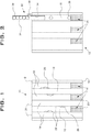
- FIG. 1 shows a particulate filter 10 for the exhaust system of an internal combustion engine after it has undergone a cleaning procedure during engine maintenance.
- the filter 10 may be formed from a porous ceramic material and comprises a number of elongate cells which are open at one end and closed at the other.
- the filter 10 has an exhaust inlet side 12 and an exhaust outlet side 14.
- the cells are divided into inlet cells 16 which are open on the exhaust inlet side 12 of the filter 10, and outlet cells 18 which are open on the exhaust outlet side 14 of the filter 10.
- the inlet and outlet cells 16,18 alternate across the filter 10, such that each pair of adjacent cells 16,18 are open on opposing sides of the filter 10.
- each cell is closed off by an end wall 20 which is integrally formed with the elongate side walls 22 which separate the inlet and outlet cells 16,18 from one another.
- the filter may be formed such that each cells is open at either end, and one end may then be closed by plugs (not shown) which are inserted into an open end of every second cell.
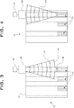
- Figures 2 to 4 show a first embodiment of an apparatus for measuring ash deposit levels in a particulate filter comprising at least one filter cell.
- Figure 2 shows reflective indicator components being inserted into an inlet cell 16 of the filter 10 in order to measure the level of ash deposits remaining in the cell 16.
- the reflective components may simply be inserted or dropped into the cell 16 by hand or, as shown here in figure 2 , a dedicated dispenser 30 may be employed for the purpose.
- the dispenser 30 comprises an elongate tubular body 32 having an internal dispensing passage 34.
- a release member 36 is at least partially located within the passage 34 and is selectively moveable between a first position in which the reflective components are held in the passage 34 (the position shown in figure 2 ) and a second position in which one or more of the reflective components are released from the dispenser 30.
- the components are capable of reflecting light, sound, or other forms of energy.
- the reflective components may take a number of forms such as, for example, metallic flakes.
- the reflective components are reflective balls 38.
- the balls are formed from a reflective material or alternatively may have a reflective coating applied to their exterior surface. They may be solid but may alternatively be hollow depending on operational requirements. Whether solid or hollow, the balls 38 may have a diameter in the range 0.6mm to 1.4mm.
- Figure 3 schematically illustrates a first radiation source which emits radiation in order to locate the reflective balls 38 inserted into the inlet cell 16 and now lying upon the ash deposits 24 in the bottom of the cell 16.
- radiation is used in this specification to refer to energy emitted from a source in the form of rays or waves such as heat, light or sound, for example.
- the radiation emitted is in the form of sound waves wherein the radiation source is an ultrasonic sensor or transceiver 40.
- the sensor 40 emits ultrasound waves 42 towards the reflective balls 38 within the cell 16.
- a processor 50 is connected to the sensor 40 in order to calculate the deposit level within the cell 16 based on reflected sound waves 44 detected by the sensor 40.
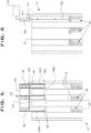
- Figures 5 to 7 show a second embodiment of an apparatus for measuring ash deposit levels in a particulate filter comprising at least one filter cell.
- the filter 10 is the same as that shown in figure 1 .
- reflective indicator balls 38 may be inserted or dropped into the cells of the filter 10 manually but alternatively the balls 38 may be loaded into a dispenser 130.
- the dispenser 130 is similar to that of the first embodiment but is arranged so that it may simultaneously dispense balls 38 into a number of inlet or outlet cells.
- the dispenser has a plurality of elongate tubes 132 which are arranged in parallel with one another and connected together by a housing 140.
- the dispenser 130 may have any number of tubes 132 but in the illustrated embodiment there are first, second and third tubes 132A-C.
- Each tube 132A-C has an internal dispensing passage 134.
- a release member 136 is at least partially located within each passage 134 and is selectively moveable between a first position in which the reflective balls 38 are held in their respective passages 134 (as shown in figure 5 ) and a second position in which one or more of the reflective balls 138 are released from each tube 132A-C.
- the release member 136 is partially located within the passage 134 of the first tube 132A, but extends all the way through the passages 134 of the second and third tubes 132B,132C.
- the release member 136 is provided with release apertures 142,144 adjacent the second and third tubes 132B,132C. These apertures 142,144 are sized to allow the reflective balls 38 to pass through them but are offset from the centre axes of the second and third tubes 132B,132C when the release member 136 is in the first position.
- the release member 136 is moved to the second position, the free end of the member 136 leaves the first tube 132A and the apertures 142,144 align with the centre axes of the second and third tubes 132B,132C. In this way the release member 136 simultaneously releases balls 38 in all three tubes 132A-C.
- Figure 6 schematically illustrates a second radiation source which emits radiation in order to locate the reflective balls 38 inserted into the inlet cell 16 and now lying upon the ash deposits 24 in the bottom of the cell 16.
- the radiation source is a laser 150 which emits radiation in the form of a beam of light.
- the laser 150 emits a beam of light 152 in the direction of the reflective balls 38 within the cell 16.
- a processor 170 is connected to a sensor 160 in order to calculate the deposit level within the cell 16 based on a reflected light beam 154.
- Figure 8 shows a third embodiment of an apparatus for measuring ash deposit levels in a particulate filter comprising at least one filter cell.
- the third embodiment of the apparatus includes indicator balls 238 which are inserted into the cell(s) 16 of the filter 10 so as to lie upon any ash deposits remaining in the cells 16.
- the apparatus also includes a radiation source in the form of a heat source, or heater, 250, and a sensor to detect the position of the balls 238 within the cell(s) 16 in the form of a thermal imaging camera 260.
- a processor 270 is connected to the camera 260 so that the two may communicate with one another.
- the cleaned particulate filter 10 is taken and one or more of the reflective balls 38 are inserted into at least one cell 16 of the filter 10.
- the balls 38 may be inserted by hand or may be inserted using the dispenser 30. If the dispenser 30 is used the operator will align the tube 32 of the dispenser 30 with the cells of the filter 10 in which measurement is to take place, and may partially insert the tube 32 into the cell 16 to ensure safe dispensing of the balls 38. Pulling back the release member 36 then permits one or more balls 38 to drop out of the dispenser 30 into the cell 16.
- the balls 38 will contact the ash deposits 26 clinging to the walls 22 of the filter 10 and knock them off the walls 22 towards the end wall 20 of the cell 16.
- the balls 38 may be of a size and/or density sufficient to knock any ash deposits from the side walls 22 but that also ensures the balls 38 land upon the surface of the ash in the bottom of the cell 16, as opposed to breaking through the surface where they would be submerged or only partially exposed on the surface of the ash.
- the radiation source in the form of ultrasonic sensor, or transceiver, 40 is positioned at the open end of the cell 16 as shown in figure 3 .
- the sensor 40 is positioned so that it abuts the inlet side 12 of the filter 10.
- the sensor 40 emits ultrasound waves 42 into the cell 16 in the direction of the balls 38 lying on the ash deposit layer.
- the reflective nature of the balls 38 means that the ultrasound waves 42 are reflected by the balls 38 back towards the sensor 40 in the form of reflected waves 44.
- the sensor 40 detects the position of the balls 38 on the basis of the reflected waves 44, and then communicates this data to the processor 50.
- the processor 50 calculates the deposit level of ash remaining in the cleaned filter 10 and displays this information to the operator.
- the processor will have been previously provided with stored data equating to a brand new or completely clean filter, as well as ranges of measured deposit depths which constitute acceptable and unacceptable levels of cleanliness in the filter 10.
- the processor 50 may indicate to the operator whether the filter 10 is sufficiently clean to return to service or else whether further cleaning is required.
- the indicator balls 38 are removed from the filter 10, along with any remaining ash deposits if present, prior to the filter 10 being returned into service.
- the indicator balls 38 are dropped into the cells 16 of the filter 10 either by hand or by way of the dispenser 130. Where the dispenser 130 is used, the tubes 132A-C are aligned with, or partially inserted into, the cells 16. The release member 136 is then pulled out to release balls 38 from all three tubes 132A-C simultaneously. As in the first embodiment, the balls 38 knock ash deposits 26 from the walls of the cells 16 as they fall, prior to landing upon either the inside surface of the end walls 20 or upon any ash deposits lying on the end walls 20. Again, as with the first embodiment the balls 38 are of a size and/or density which means they do not penetrate through the ash but instead lie upon the surface thereof.
- the laser 150 is positioned at the open end of one of the cells 16.
- a beam of light 152 is emitted from the laser into the cell 16 in the direction of the balls 38.
- the beam 152 hits one or more of the balls 38 and is reflected back up the cell 16 as reflected beam 154, where it is detected by the sensor 160.
- the sensor 160 communicates this detection data to the processor 170, which then calculates the deposit level of ash remaining in the cleaned filter 10 and displays this information to the operator.
- the processor 170 will have been previously provided with stored data equating to a brand new or completely clean filter, as well as ranges of measured deposit depths which constitute acceptable and unacceptable levels of ash in the filter 10. Thus, the processor 170 may indicate to the operator whether the filter 10 is sufficiently clean to return to service or else whether further cleaning is required.
- the indicator balls 38 are removed from the filter 10, along with any remaining ash deposits if present, prior to the filter 10 being returned into service.
- the indicator balls 238 are not reflective but are instead initially heated by a radiation source in the form of heater 250.
- the balls 238 are then inserted into the filter cell 16 by hand or by way of one of the dispensers 30,130 used in the first and second embodiments. As they have been heated, the balls 238 emit radiation in the form of heat into the cell once they have been inserted into the filter 10 and lie upon any ash deposits 24 remaining in the cell 16.
- the thermal imaging camera 260 or other heat sensing device is then positioned at a suitable reference point on the outside of the filter 10 so that it may detect the position of the heat radiating balls(s) 238.
- the camera 260 then communicates the positional data to the processor 270, which then calculates the ash deposit level within the cell 16 on the basis of the positional data received from the camera 260.
- the processor 270 will have been previously provided with data equating to a brand new or completely clean filter, as well as ranges of measured deposit depths which constitute acceptable and unacceptable levels of ash in the filter 10. Thus, the processor 270 may indicate to the operator whether the filter 10 is sufficiently clean to return to service or else whether further cleaning is required.
- the indicator balls 238 are removed from the filter 10, along with any remaining ash deposits if present, prior to the filter 10 being returned into service.
- the present disclosure presents a method and apparatus for measuring ash deposit levels in particulate filters which is cheaper and simpler than invasive inspection and measurement techniques, thereby reducing the cost and time of checking a cleaned filter. Furthermore, the method and apparatus of the present disclosure present clearer and more accurate measurements than existing non-invasive inspection and measurement techniques.
- the third embodiment of the disclosure may be modified to present a further, fourth embodiment of method and apparatus for measuring ash levels in a particulate filter.
- the heater 250 is placed on the opposite side of the filter 10 from the thermal imaging camera 260 and emits radiation in the form of heat across the filter 10 into the cells 16 in the direction of the camera 260.
- Unheated indicator components such as indicator balls for example, are then inserted into the cells in a manner already described above. The position of these unheated indicator components can then be detected against the background of radiated heat emitting from the heater 250, and this positional data can then be employed by the processor 270 to calculate the deposit level in the cells 16.
- the indicator balls may be sized such that their diameter is only slightly less than that of the filter cell. As a result, a plurality of balls dropped or inserted into a cell will stack on top of one another until no more balls will fit in the cell. By knowing the diameter of the balls and counting the number of balls needed to fill a cell, the depth of ash deposits left in the cell can also be measured in this manner. In the instance where a dispenser is used to insert the balls into a cell or cells, the counting of the balls could be effected by modifying the dispenser to include a counting mechanism which counts the number of balls or other indicators dispensed from the or each dispensing tube into the cells.
Landscapes
- Engineering & Computer Science (AREA)
- Chemical & Material Sciences (AREA)
- Combustion & Propulsion (AREA)
- Mechanical Engineering (AREA)
- General Engineering & Computer Science (AREA)
- Physics & Mathematics (AREA)
- Chemical Kinetics & Catalysis (AREA)
- Electromagnetism (AREA)
- Thermal Sciences (AREA)
- Fluid Mechanics (AREA)
- General Physics & Mathematics (AREA)
- Sampling And Sample Adjustment (AREA)
- Investigating Or Analysing Materials By Optical Means (AREA)
- Investigating, Analyzing Materials By Fluorescence Or Luminescence (AREA)
- Processes For Solid Components From Exhaust (AREA)
Description
- The invention relates to the field of particulate filters, and in particular the invention relates to diesel particulate filters used in internal combustion engines. More specifically, the invention relates to a method and apparatus of measuring ash deposit levels in such filters.
- Particulate filters are used in internal combustion engines, and especially diesel engines, to capture soot or ash present in the exhaust gas of the engine. The filters typically comprise a number of elongate cells which are generally aligned with the direction of the flow of exhaust gas when the filter is in use. The cells are open at one end and closed at the other end so that the gas may flow through and out of the cells but the soot and ash will be captured on the cell walls and remain in the filter. Adjacent cells usually face in opposing directions, with one cell open to the exhaust inlet side of the filter and the adjacent cell open to the exhaust outlet side of the filter.
- In order to maintain their filtration performance some diesel particulate filters have a degree of autoselective regeneration, where the filter is regularly cleaned automatically whilst still in place within the exhaust system. There are numerous filter regeneration methods such as, for example, electrical discharge regeneration or gas discharge regeneration using nitrogen oxide. Whilst the regeneration of the filter in situ removes the majority of the soot captured in the filter cells, the performance of the filter will still diminish over a period of prolonged use, since the ash component in the filter is not reduceable with regeneration. It is therefore important for the filter to be removed and cleaned as part of regular engine servicing procedures. It is equally important that a proper inspection of the cleaned filter is then carried out before the filter is put back into service, otherwise the filter performance may diminish to an undesirable level before the next scheduled engine service is reached.
- Given the relatively small diameter of the cells in the filter it is difficult to access the cells and carry out a proper inspection. One invasive inspection technique uses a borescope to view the interior of each cell in order to determine cleanliness. However, borescopes are expensive and also require servicing personnel to be trained in order to operate them properly. Alternative, non-invasive inspection methods have also been devised. One such method is to measure the air pressure drop across the cleaned filter and compare it to a base value for a brand new filter. However, given the extremely low density of the ash particles it is very difficult to accurately establish whether deposits remain in the cleaned filter using this method. Another non-invasive method uses ultrasound waves which are directed into the filter cells and then a reading is taken of the waves reflected from the ash deposits lying in the cells. However, as the ash in the cells does not reflect the ultrasound waves well, the resultant ultrasound image presented to the user is usually unclear and unhelpful in determining whether ash is still present in the cleaned filter or not. In addition, ash which sticks to the longitudinal walls of the cells tends to disrupt the signal reflected from the main deposit against the end wall, which again presents an unclear image to the operator.
-
US 7,157,919 B1 discloses a system and method for detecting soot and or ash loading within a filter. The method comprises the steps of transmitting a source RF signal through a filter, measuring a reflected RF signal, measuring a transmitted RF signal, calculating reflected power by comparing the source RF signal with the reflected RF signal, calculating attenuated power by comparing the source RF signal with the transmitted RF signal, and determining soot loading based on reflected power and transmitted power. Said system and method may also determine ash loading. - A particulate sensing system for a particulate trap including a radio frequency transmit circuit and a radio frequency receive circuit is disclosed in
US 2007/0024289 A1 . -
US 7,698,945 B2 discloses a system and method for detecting internal flaws in a particulate filter. - According to a first aspect of the disclosure there is provided a method of measuring ash deposit levels in a particulate filter comprising at least one cell. The method comprises inserting one or more indicator components into the at least one cell so as to lie upon any deposits contained therein. Radiation is emitted from a radiation source into the cell, and the position of the one or more indicator components is detected on the basis of the emitted radiation. The deposit level within the cell is then calculated on the basis of the position of the one or more indicator components.
- According to a second aspect of the disclosure there is provided a method of cleaning a particulate filter having at least one cell. The method comprises removing deposits contained in the at least one cell, and then inserting one or more indicator components into the at least one cell so as to lie upon any deposits contained therein. Radiation is emitted from a radiation source into the cell, and the position of the one or more indicator components is detected on the basis of the emitted radiation. The deposit level within the cell is then calculated on the basis of the position of the one or more indicator components. The one or more reflective components and any remaining deposits are then removed from the cell.
- According to a third aspect of the disclosure there is provided an apparatus for measuring ash deposit levels in a particulate filter comprising at least one cell. The apparatus comprises a radiation source for emitting radiation into the at least one cell, and one or more indicator components insertable into the at least one cell. The apparatus further comprises at least one radiation detection sensor which detects the position of the one or more indicator components on the basis of the emitted radiation, and a processor which calculates an ash deposit level on the basis of the reflected radiation.
- Preferred embodiments of the disclosure will now be described, by way of example only, with reference to the accompanying drawings.
-
Figure 1 shows a vertical cross section through a schematic representation of a particulate filter; -
Figures 2-4 show a first embodiment of the disclosure, in which:-
Figure 2 shows reflective components being inserted into the filter ofFigure 1 ;
-
-
Figure 3 shows ultrasound waves being emitted in the direction of the reflective components in the filter; and -
Figure 4 shows the ultrasound waves being reflected back from the reflective components to a receiver. -
Figures 5-7 show a second embodiment of the disclosure in which: -
Figure 5 shows reflective components being inserted into the filter ofFigure 1 ; -
Figure 6 shows a beam of light being emitted in the direction of the reflective components in the filter; and -
Figure 7 shows the beam of light being reflected back from the reflective components to a receiver. -
Figure 8 shows a third embodiment of the disclosure. - As stated above, the figures show three embodiments of the disclosure in which a particulate filter is shown schematically by way of a vertical section view. The filter shown in the figures comprises six cells for illustrative purposes, but it will be appreciated that the filter may comprise one or more cells as desired.
-
Figure 1 shows aparticulate filter 10 for the exhaust system of an internal combustion engine after it has undergone a cleaning procedure during engine maintenance. Thefilter 10 may be formed from a porous ceramic material and comprises a number of elongate cells which are open at one end and closed at the other. Thefilter 10 has anexhaust inlet side 12 and anexhaust outlet side 14. The cells are divided intoinlet cells 16 which are open on theexhaust inlet side 12 of thefilter 10, andoutlet cells 18 which are open on theexhaust outlet side 14 of thefilter 10. The inlet andoutlet cells filter 10, such that each pair ofadjacent cells filter 10. The closed ends of each cell are closed off by anend wall 20 which is integrally formed with theelongate side walls 22 which separate the inlet andoutlet cells - In
figure 1 it can be seen that despite the filter having been cleaned,ash deposits 24 remain in the bottom of theinlet cells 16. In addition,ash deposits 26 are also still present on theside walls 22 of thecells 16. If the filter were to be returned to operational use in this state it would become overloaded with ash quicker than expected, and most likely some time before it was due to be cleaned again. -
Figures 2 to 4 show a first embodiment of an apparatus for measuring ash deposit levels in a particulate filter comprising at least one filter cell.Figure 2 shows reflective indicator components being inserted into aninlet cell 16 of thefilter 10 in order to measure the level of ash deposits remaining in thecell 16. The reflective components may simply be inserted or dropped into thecell 16 by hand or, as shown here infigure 2 , adedicated dispenser 30 may be employed for the purpose. Thedispenser 30 comprises an elongatetubular body 32 having aninternal dispensing passage 34. Arelease member 36 is at least partially located within thepassage 34 and is selectively moveable between a first position in which the reflective components are held in the passage 34 (the position shown infigure 2 ) and a second position in which one or more of the reflective components are released from thedispenser 30. - By "reflective" it is meant that the components are capable of reflecting light, sound, or other forms of energy. The reflective components may take a number of forms such as, for example, metallic flakes. However, in the illustrated embodiments shown the reflective components are
reflective balls 38. The balls are formed from a reflective material or alternatively may have a reflective coating applied to their exterior surface. They may be solid but may alternatively be hollow depending on operational requirements. Whether solid or hollow, theballs 38 may have a diameter in the range 0.6mm to 1.4mm. -
Figure 3 schematically illustrates a first radiation source which emits radiation in order to locate thereflective balls 38 inserted into theinlet cell 16 and now lying upon theash deposits 24 in the bottom of thecell 16. The term "radiation" is used in this specification to refer to energy emitted from a source in the form of rays or waves such as heat, light or sound, for example. In this first illustrated embodiment, the radiation emitted is in the form of sound waves wherein the radiation source is an ultrasonic sensor ortransceiver 40. Thesensor 40 emits ultrasound waves 42 towards thereflective balls 38 within thecell 16. Aprocessor 50 is connected to thesensor 40 in order to calculate the deposit level within thecell 16 based on reflectedsound waves 44 detected by thesensor 40. -
Figures 5 to 7 show a second embodiment of an apparatus for measuring ash deposit levels in a particulate filter comprising at least one filter cell. Thefilter 10 is the same as that shown infigure 1 . As in the first embodiment,reflective indicator balls 38 may be inserted or dropped into the cells of thefilter 10 manually but alternatively theballs 38 may be loaded into adispenser 130. Thedispenser 130 is similar to that of the first embodiment but is arranged so that it may simultaneously dispenseballs 38 into a number of inlet or outlet cells. The dispenser has a plurality of elongate tubes 132 which are arranged in parallel with one another and connected together by ahousing 140. Thedispenser 130 may have any number of tubes 132 but in the illustrated embodiment there are first, second andthird tubes 132A-C. Eachtube 132A-C has aninternal dispensing passage 134. Arelease member 136 is at least partially located within eachpassage 134 and is selectively moveable between a first position in which thereflective balls 38 are held in their respective passages 134 (as shown infigure 5 ) and a second position in which one or more of the reflective balls 138 are released from eachtube 132A-C. - The
release member 136 is partially located within thepassage 134 of thefirst tube 132A, but extends all the way through thepassages 134 of the second andthird tubes 132B,132C. Therelease member 136 is provided with release apertures 142,144 adjacent the second andthird tubes 132B,132C. These apertures 142,144 are sized to allow thereflective balls 38 to pass through them but are offset from the centre axes of the second andthird tubes 132B,132C when therelease member 136 is in the first position. When therelease member 136 is moved to the second position, the free end of themember 136 leaves thefirst tube 132A and the apertures 142,144 align with the centre axes of the second andthird tubes 132B,132C. In this way therelease member 136 simultaneously releasesballs 38 in all threetubes 132A-C. -
Figure 6 schematically illustrates a second radiation source which emits radiation in order to locate thereflective balls 38 inserted into theinlet cell 16 and now lying upon theash deposits 24 in the bottom of thecell 16. In this second illustrated embodiment, the radiation source is alaser 150 which emits radiation in the form of a beam of light. Thelaser 150 emits a beam oflight 152 in the direction of thereflective balls 38 within thecell 16. Aprocessor 170 is connected to asensor 160 in order to calculate the deposit level within thecell 16 based on a reflectedlight beam 154. -
Figure 8 shows a third embodiment of an apparatus for measuring ash deposit levels in a particulate filter comprising at least one filter cell. The third embodiment of the apparatus includesindicator balls 238 which are inserted into the cell(s) 16 of thefilter 10 so as to lie upon any ash deposits remaining in thecells 16. The apparatus also includes a radiation source in the form of a heat source, or heater, 250, and a sensor to detect the position of theballs 238 within the cell(s) 16 in the form of athermal imaging camera 260. Aprocessor 270 is connected to thecamera 260 so that the two may communicate with one another. - Methods of measuring ash deposit levels in a particulate filter comprising at least one filter cell will now be described, with reference to
figures 1 to 8 . - A first embodiment of the method will be described with reference to
figures 1 to 4 . Firstly, the cleanedparticulate filter 10 is taken and one or more of thereflective balls 38 are inserted into at least onecell 16 of thefilter 10. Theballs 38 may be inserted by hand or may be inserted using thedispenser 30. If thedispenser 30 is used the operator will align thetube 32 of thedispenser 30 with the cells of thefilter 10 in which measurement is to take place, and may partially insert thetube 32 into thecell 16 to ensure safe dispensing of theballs 38. Pulling back therelease member 36 then permits one ormore balls 38 to drop out of thedispenser 30 into thecell 16. - As the
balls 38 fall into thecell 16 they will contact theash deposits 26 clinging to thewalls 22 of thefilter 10 and knock them off thewalls 22 towards theend wall 20 of thecell 16. Theballs 38 may be of a size and/or density sufficient to knock any ash deposits from theside walls 22 but that also ensures theballs 38 land upon the surface of the ash in the bottom of thecell 16, as opposed to breaking through the surface where they would be submerged or only partially exposed on the surface of the ash. - Once the balls have been inserted into the
cell 16, the radiation source in the form of ultrasonic sensor, or transceiver, 40 is positioned at the open end of thecell 16 as shown infigure 3 . To ensure consistent measurement thesensor 40 is positioned so that it abuts theinlet side 12 of thefilter 10. Thesensor 40 emits ultrasound waves 42 into thecell 16 in the direction of theballs 38 lying on the ash deposit layer. As shown infigure 4 , the reflective nature of theballs 38 means that the ultrasound waves 42 are reflected by theballs 38 back towards thesensor 40 in the form of reflected waves 44. Thesensor 40 detects the position of theballs 38 on the basis of the reflected waves 44, and then communicates this data to theprocessor 50. Theprocessor 50 then calculates the deposit level of ash remaining in the cleanedfilter 10 and displays this information to the operator. The processor will have been previously provided with stored data equating to a brand new or completely clean filter, as well as ranges of measured deposit depths which constitute acceptable and unacceptable levels of cleanliness in thefilter 10. Thus, theprocessor 50 may indicate to the operator whether thefilter 10 is sufficiently clean to return to service or else whether further cleaning is required. Theindicator balls 38 are removed from thefilter 10, along with any remaining ash deposits if present, prior to thefilter 10 being returned into service. - A number of the steps of the second embodiment, illustrated in
figures 5 to 7 , are similar to those of the first embodiment. Initially, theindicator balls 38 are dropped into thecells 16 of thefilter 10 either by hand or by way of thedispenser 130. Where thedispenser 130 is used, thetubes 132A-C are aligned with, or partially inserted into, thecells 16. Therelease member 136 is then pulled out to releaseballs 38 from all threetubes 132A-C simultaneously. As in the first embodiment, theballs 38knock ash deposits 26 from the walls of thecells 16 as they fall, prior to landing upon either the inside surface of theend walls 20 or upon any ash deposits lying on theend walls 20. Again, as with the first embodiment theballs 38 are of a size and/or density which means they do not penetrate through the ash but instead lie upon the surface thereof. - Once the
balls 38 are in thecells 16, thelaser 150 is positioned at the open end of one of thecells 16. A beam oflight 152 is emitted from the laser into thecell 16 in the direction of theballs 38. Thebeam 152 hits one or more of theballs 38 and is reflected back up thecell 16 as reflectedbeam 154, where it is detected by thesensor 160. Thesensor 160 communicates this detection data to theprocessor 170, which then calculates the deposit level of ash remaining in the cleanedfilter 10 and displays this information to the operator. Theprocessor 170 will have been previously provided with stored data equating to a brand new or completely clean filter, as well as ranges of measured deposit depths which constitute acceptable and unacceptable levels of ash in thefilter 10. Thus, theprocessor 170 may indicate to the operator whether thefilter 10 is sufficiently clean to return to service or else whether further cleaning is required. Theindicator balls 38 are removed from thefilter 10, along with any remaining ash deposits if present, prior to thefilter 10 being returned into service. - In the third embodiment illustrated in
figure 8 , theindicator balls 238 are not reflective but are instead initially heated by a radiation source in the form ofheater 250. Theballs 238 are then inserted into thefilter cell 16 by hand or by way of one of the dispensers 30,130 used in the first and second embodiments. As they have been heated, theballs 238 emit radiation in the form of heat into the cell once they have been inserted into thefilter 10 and lie upon anyash deposits 24 remaining in thecell 16. Thethermal imaging camera 260 or other heat sensing device is then positioned at a suitable reference point on the outside of thefilter 10 so that it may detect the position of the heat radiating balls(s) 238. Thecamera 260 then communicates the positional data to theprocessor 270, which then calculates the ash deposit level within thecell 16 on the basis of the positional data received from thecamera 260. - The
processor 270 will have been previously provided with data equating to a brand new or completely clean filter, as well as ranges of measured deposit depths which constitute acceptable and unacceptable levels of ash in thefilter 10. Thus, theprocessor 270 may indicate to the operator whether thefilter 10 is sufficiently clean to return to service or else whether further cleaning is required. Theindicator balls 238 are removed from thefilter 10, along with any remaining ash deposits if present, prior to thefilter 10 being returned into service. - The present disclosure presents a method and apparatus for measuring ash deposit levels in particulate filters which is cheaper and simpler than invasive inspection and measurement techniques, thereby reducing the cost and time of checking a cleaned filter. Furthermore, the method and apparatus of the present disclosure present clearer and more accurate measurements than existing non-invasive inspection and measurement techniques.
- The third embodiment of the disclosure may be modified to present a further, fourth embodiment of method and apparatus for measuring ash levels in a particulate filter. In the modified embodiment, the
heater 250 is placed on the opposite side of thefilter 10 from thethermal imaging camera 260 and emits radiation in the form of heat across thefilter 10 into thecells 16 in the direction of thecamera 260. Unheated indicator components, such as indicator balls for example, are then inserted into the cells in a manner already described above. The position of these unheated indicator components can then be detected against the background of radiated heat emitting from theheater 250, and this positional data can then be employed by theprocessor 270 to calculate the deposit level in thecells 16. - It should be understood that whilst indicator dispensers 30,130 have been described with respect to the first and second embodiments, respectively, either of these dispensers may be used in any of the embodiments described herein.
- The indicator balls may be sized such that their diameter is only slightly less than that of the filter cell. As a result, a plurality of balls dropped or inserted into a cell will stack on top of one another until no more balls will fit in the cell. By knowing the diameter of the balls and counting the number of balls needed to fill a cell, the depth of ash deposits left in the cell can also be measured in this manner. In the instance where a dispenser is used to insert the balls into a cell or cells, the counting of the balls could be effected by modifying the dispenser to include a counting mechanism which counts the number of balls or other indicators dispensed from the or each dispensing tube into the cells.
- It will be apparent to those skilled in the art that various modifications and variations can be made to the apparatus and method. Other embodiments will be apparent to those skilled in the art from consideration of the specification and practice of the disclosed apparatus and method. It is intended that the specification and examples be considered as exemplary only, with a true scope being indicated by the following claims and their equivalents.
Claims (15)
- A method of measuring ash deposit levels in a particulate filter (10) comprising at least one cell (16), the method comprising the steps of:inserting one or more indicator components (38; 238) into the at least one cell (16) so as to lie upon any deposits (24) contained therein;emitting radiation from a radiation source (150) into the cell (16);detecting the position of the one or more indicator components (38; 238) on the basis of the emitted radiation; andcalculating the deposit level within the cell (16) on the basis of the position of the indicator components (38; 238).
- The method of claim 1, wherein the indicator components are reflective components and the radiation is emitted towards the one or more reflective components (38; 238) in the cell (16), and wherein the position of the reflective components (38; 238) is detected by detecting radiation reflected back from the one or more reflective components (38; 238).
- The method of claim 2, wherein the emitted radiation comprises ultrasound waves (42, 44) or a beam of light (152).
- The method of claim 1, wherein the radiation source is a heat source (250) and the method further comprises the step of heating the indicator components (38; 238) with the heat source (250) prior to their insertion into the cell (16), whereby the inserted indicator components (38; 238) emit heat into the cell (16).
- The method of claim 1, wherein the one or more indicator components are inserted into the at least one cell (16) by a dispenser (30; 130).
- A method of cleaning a particulate filter (10) having at least one cell (16), the method comprising:removing deposits (24) contained in the at least one cell (16);measuring ash deposit levels in the filter (10) according to the method of any one of the preceding claims; andremoving the one or more indicator components (38; 238) and any remaining deposits (24) from the cell (16).
- An apparatus for measuring ash deposit levels in a particulate filter (10) comprising at least one cell (16), the apparatus comprising:a radiation source (150) for emitting radiation into the at least one cell (16);one or more indicator components (38; 238) insertable into the at least one cell (16);at least one radiation detection sensor (40; 140; 160) configured to detect the position of the one or more indicator components (38; 238) on the basis of the emitted radiation; anda processor (50; 170; 270) configured to calculate an ash deposit level on the basis of the detected position of the indicator components (38; 238).
- The apparatus of claim 7, wherein the indicator components are balls (38; 138; 238), each ball (38; 138; 238) having a diameter of between 0.6mm and 1.4mm and/or is hollow.
- The apparatus of claim 7, wherein the radiation source (150) is configured to emit radiation into the cell (16), and the one or more indicator components (38; 238) are radiation reflecting components configured to reflect radiation emitted from the radiation source, and wherein the at least one radiation detection sensor (40; 140; 160) is configured to detect radiation reflected from the one or more reflecting components (38; 238).
- The apparatus of claim 9, wherein the one or more reflective components (38; 238) is formed from a reflective material or coated with a reflective material.
- The apparatus of claim 7, wherein the radiation source is a heat source (250) configured to heat the indicator components (38; 238) prior to their insertion into the at least one cell (16), and wherein the indicator components (38; 238) are configured to emit heat into the cell (16).
- The apparatus of claim 8, further comprising a dispenser (30; 130) containing the one or more balls (38; 138; 238) for insertion into the at least one cell (16).
- The apparatus of claim 12, wherein the dispenser (30; 130) comprises an elongate tube (32; 132) in which the one or more balls (38; 138; 238) are located, and a release member (36; 136) moveable between a first position in which the balls (38; 138; 238) are held in the dispenser (30; 130) and a second position in which one or more of the balls (38; 138; 238) are released from the dispenser (30; 130) into one or more cells (16).
- The apparatus of claim 12, wherein the dispenser (30; 130) comprises a plurality of elongate tubes (32; 132) arranged in parallel with one another with each elongate tube (32; 132) containing one or more of the balls (38; 138; 238), and a release member (36; 136) moveable between a first position in which the balls (38; 138; 238) are held in the tubes (32; 132) and a second position in which one or more of the balls (38; 138; 238) are released from each tube (32; 132) into a number of cells (16).
- The apparatus of claim 9, wherein the radiation source is an ultrasonic transmitter configured to emit radiation in the form of ultrasound waves (42, 44), or a laser (150) configured to emit radiation in the form of a beam of light (152).
Applications Claiming Priority (3)
| Application Number | Priority Date | Filing Date | Title |
|---|---|---|---|
| US201061426588P | 2010-12-23 | 2010-12-23 | |
| US13/335,061 US8979986B2 (en) | 2010-12-23 | 2011-12-22 | Method and apparatus for measuring ash deposit levels in a particulate filter |
| PCT/US2011/066862 WO2012088426A2 (en) | 2010-12-23 | 2011-12-22 | Method and apparatus for measuring ash deposit levels in a particulate filter |
Publications (3)
| Publication Number | Publication Date |
|---|---|
| EP2655818A2 EP2655818A2 (en) | 2013-10-30 |
| EP2655818A4 EP2655818A4 (en) | 2015-07-15 |
| EP2655818B1 true EP2655818B1 (en) | 2017-01-18 |
Family
ID=46314942
Family Applications (1)
| Application Number | Title | Priority Date | Filing Date |
|---|---|---|---|
| EP11852147.5A Active EP2655818B1 (en) | 2010-12-23 | 2011-12-22 | Method and apparatus for measuring ash deposit levels in a particulate filter |
Country Status (4)
| Country | Link |
|---|---|
| US (2) | US8979986B2 (en) |
| EP (1) | EP2655818B1 (en) |
| AU (1) | AU2011348158B2 (en) |
| WO (1) | WO2012088426A2 (en) |
Families Citing this family (8)
| Publication number | Priority date | Publication date | Assignee | Title |
|---|---|---|---|---|
| US8832957B2 (en) * | 2012-07-26 | 2014-09-16 | Caterpillar Inc. | Apparatus and method for determining ash height in a filter |
| EP2888062A4 (en) | 2012-08-24 | 2016-03-23 | Cummins Ip Inc | PROCESS FOR PURIFYING AND REPLACING AN EXHAUST COMPONENT |
| EP2927443A1 (en) | 2014-04-02 | 2015-10-07 | Caterpillar Inc. | Apparatus and method for detecting urea deposit formation |
| EP3895592A1 (en) | 2017-09-28 | 2021-10-20 | TTI (Macao Commercial Offshore) Limited | Dirt collector for a vacuum cleaner |
| KR102624510B1 (en) | 2018-10-01 | 2024-01-16 | 삼성디스플레이 주식회사 | Laser irradiation apparatus, driving method thereof, and method for fabricating display device using the same |
| US11156192B2 (en) * | 2019-04-04 | 2021-10-26 | Deere & Company | Air intake screen debris sensing |
| CN110131017B (en) * | 2019-06-14 | 2020-11-13 | 湘潭大学 | Method for predicting ash deposition amount of automobile particulate filter and regeneration system |
| CN113029277A (en) * | 2021-03-02 | 2021-06-25 | 严立敏 | Farmland water level monitoring equipment with water utilization coefficient |
Family Cites Families (17)
| Publication number | Priority date | Publication date | Assignee | Title |
|---|---|---|---|---|
| US4130018A (en) * | 1977-08-30 | 1978-12-19 | Envirotech Corporation | Ultrasonic transducer with reference reflector |
| US5235416A (en) * | 1991-07-30 | 1993-08-10 | The Government Of The United States Of America As Represented By The Secretary Of The Department Of Health & Human Services | System and method for preforming simultaneous bilateral measurements on a subject in motion |
| US5184510A (en) * | 1991-12-23 | 1993-02-09 | Ford Motor Company | Liquid level sensor |
| US6356782B1 (en) * | 1998-12-24 | 2002-03-12 | Vivant Medical, Inc. | Subcutaneous cavity marking device and method |
| JP2002357140A (en) * | 2001-05-31 | 2002-12-13 | Komatsu Ltd | Exhaust gas purification device for internal combustion engine |
| US7217913B2 (en) * | 2003-12-18 | 2007-05-15 | Micron Technology, Inc. | Method and system for wavelength-dependent imaging and detection using a hybrid filter |
| DE502005003454D1 (en) | 2004-02-12 | 2008-05-08 | Daimler Ag | DEVICE FOR DETERMINING THE CONDITION OF A PARTICULAR FILTER |
| EP1645241B1 (en) * | 2004-10-05 | 2011-12-28 | BrainLAB AG | Position marker system with point light sources |
| US7157919B1 (en) | 2005-07-26 | 2007-01-02 | Caterpillar Inc. | Method and system for detecting soot and ash concentrations in a filter |
| US7253641B2 (en) * | 2005-07-26 | 2007-08-07 | Caterpillar Inc. | Radio frequency particulate sensing system |
| US7334401B2 (en) | 2006-01-19 | 2008-02-26 | Gm Global Technology Operations, Inc. | Apparatus for sensing particulates in a gas flow stream |
| US7548272B2 (en) * | 2006-06-07 | 2009-06-16 | Onlive, Inc. | System and method for performing motion capture using phosphor application techniques |
| US20100231692A1 (en) * | 2006-07-31 | 2010-09-16 | Onlive, Inc. | System and method for performing motion capture and image reconstruction with transparent makeup |
| DE102007049668B3 (en) * | 2007-10-17 | 2009-04-16 | Aesculap Ag | Method and device for determining the angular position of an acetabular cup in a pelvic bone |
| US7698945B2 (en) | 2007-11-08 | 2010-04-20 | Caterpillar Inc. | System and method for detecting internal flaws in a particulate filter |
| JP5347800B2 (en) * | 2009-07-27 | 2013-11-20 | ソニー株式会社 | Detection system and detection method |
| GB201015690D0 (en) * | 2010-09-20 | 2010-10-27 | Eminox Ltd | Filter condition inspection |
-
2011
- 2011-12-22 AU AU2011348158A patent/AU2011348158B2/en active Active
- 2011-12-22 US US13/335,061 patent/US8979986B2/en active Active
- 2011-12-22 EP EP11852147.5A patent/EP2655818B1/en active Active
- 2011-12-22 WO PCT/US2011/066862 patent/WO2012088426A2/en not_active Ceased
-
2015
- 2015-02-16 US US14/623,353 patent/US9546896B2/en active Active
Non-Patent Citations (1)
| Title |
|---|
| None * |
Also Published As
| Publication number | Publication date |
|---|---|
| WO2012088426A2 (en) | 2012-06-28 |
| EP2655818A4 (en) | 2015-07-15 |
| US8979986B2 (en) | 2015-03-17 |
| US9546896B2 (en) | 2017-01-17 |
| WO2012088426A3 (en) | 2013-01-31 |
| US20120234169A1 (en) | 2012-09-20 |
| EP2655818A2 (en) | 2013-10-30 |
| AU2011348158A1 (en) | 2013-06-13 |
| US20150177046A1 (en) | 2015-06-25 |
| AU2011348158B2 (en) | 2016-04-28 |
Similar Documents
| Publication | Publication Date | Title |
|---|---|---|
| EP2655818B1 (en) | Method and apparatus for measuring ash deposit levels in a particulate filter | |
| EP2265893B1 (en) | Method and apparatus for determining pipewall thickness using one or more ultrasonic sensors | |
| RU2188413C1 (en) | Device for intrapipe ultrasonic thickness gauging | |
| RU2182331C1 (en) | Method of intrapipe ultrasonic testing | |
| RU2212660C1 (en) | Method of intratube ultrasonic testing | |
| US6363788B1 (en) | Noninvasive detection of corrosion, mic, and foreign objects in containers, using guided ultrasonic waves | |
| US20040004551A1 (en) | Fluid management system | |
| CN109917252B (en) | Method and device for positioning local discharge source in transformer and server | |
| JP2006521540A (en) | Measuring method of object position | |
| JP7029303B2 (en) | Non-destructive diagnostic method for PC grout filling state | |
| EP0018290B1 (en) | Method and apparatus for the control of fuel rods used in nuclear reactor assemblies | |
| US20110183168A1 (en) | Battery Electrolyte Level Detector Apparatus | |
| US20240329007A1 (en) | Heat exchanger cleaning apparatus and method of use thereof | |
| US7764570B2 (en) | Feedback protection of pressure measurement devices | |
| US20040004545A1 (en) | Fluid management system | |
| JP5141419B2 (en) | Soot concentration measuring device | |
| CN205015313U (en) | Ultrasonic probe for small-diameter tube rolling defects and supporting test blocks | |
| US20240345034A1 (en) | Heat exchanger state sensing apparatus and method of use thereof | |
| JP3759050B2 (en) | Ultrasonic probe holder, ultrasonic flaw detector, and ultrasonic flaw detection method for tubular body | |
| KR200411972Y1 (en) | Ultrasonic flaw detector for expansion of heat exchanger tubes | |
| CN100352892C (en) | Diagnostic device and diagnostic method for carbonization chamber of coke oven | |
| TWI656343B (en) | Water level detecting method of heat transfer tube and inspection method of heat transfer tube | |
| JP2010025886A (en) | Soot concentration measuring device | |
| CN105116057A (en) | Ultrasonic probe for detecting rolling defects of small-bore pipes and test block used with ultrasonic probe | |
| CN205353020U (en) | Small -bore pipe rolling defect ultrasonic wave detecting device |
Legal Events
| Date | Code | Title | Description |
|---|---|---|---|
| PUAI | Public reference made under article 153(3) epc to a published international application that has entered the european phase |
Free format text: ORIGINAL CODE: 0009012 |
|
| 17P | Request for examination filed |
Effective date: 20130610 |
|
| AK | Designated contracting states |
Kind code of ref document: A2 Designated state(s): AL AT BE BG CH CY CZ DE DK EE ES FI FR GB GR HR HU IE IS IT LI LT LU LV MC MK MT NL NO PL PT RO RS SE SI SK SM TR |
|
| DAX | Request for extension of the european patent (deleted) | ||
| A4 | Supplementary search report drawn up and despatched |
Effective date: 20150615 |
|
| RIC1 | Information provided on ipc code assigned before grant |
Ipc: F01N 3/021 20060101AFI20150609BHEP Ipc: F01N 11/00 20060101ALI20150609BHEP Ipc: F01N 3/023 20060101ALI20150609BHEP |
|
| RIN1 | Information on inventor provided before grant (corrected) |
Inventor name: GATZ, MICHAEL, C. Inventor name: PAINTER, DAVID Inventor name: MEISTER, STEVEN, F. |
|
| GRAP | Despatch of communication of intention to grant a patent |
Free format text: ORIGINAL CODE: EPIDOSNIGR1 |
|
| RIC1 | Information provided on ipc code assigned before grant |
Ipc: F01N 3/021 20060101AFI20160616BHEP Ipc: F01N 11/00 20060101ALI20160616BHEP Ipc: F01N 3/023 20060101ALI20160616BHEP |
|
| INTG | Intention to grant announced |
Effective date: 20160704 |
|
| GRAS | Grant fee paid |
Free format text: ORIGINAL CODE: EPIDOSNIGR3 |
|
| GRAA | (expected) grant |
Free format text: ORIGINAL CODE: 0009210 |
|
| AK | Designated contracting states |
Kind code of ref document: B1 Designated state(s): AL AT BE BG CH CY CZ DE DK EE ES FI FR GB GR HR HU IE IS IT LI LT LU LV MC MK MT NL NO PL PT RO RS SE SI SK SM TR |
|
| REG | Reference to a national code |
Ref country code: GB Ref legal event code: FG4D |
|
| REG | Reference to a national code |
Ref country code: CH Ref legal event code: EP |
|
| REG | Reference to a national code |
Ref country code: AT Ref legal event code: REF Ref document number: 863050 Country of ref document: AT Kind code of ref document: T Effective date: 20170215 |
|
| REG | Reference to a national code |
Ref country code: IE Ref legal event code: FG4D |
|
| REG | Reference to a national code |
Ref country code: DE Ref legal event code: R096 Ref document number: 602011034562 Country of ref document: DE |
|
| REG | Reference to a national code |
Ref country code: NL Ref legal event code: MP Effective date: 20170118 |
|
| REG | Reference to a national code |
Ref country code: LT Ref legal event code: MG4D |
|
| REG | Reference to a national code |
Ref country code: AT Ref legal event code: MK05 Ref document number: 863050 Country of ref document: AT Kind code of ref document: T Effective date: 20170118 |
|
| PG25 | Lapsed in a contracting state [announced via postgrant information from national office to epo] |
Ref country code: NL Free format text: LAPSE BECAUSE OF FAILURE TO SUBMIT A TRANSLATION OF THE DESCRIPTION OR TO PAY THE FEE WITHIN THE PRESCRIBED TIME-LIMIT Effective date: 20170118 |
|
| PG25 | Lapsed in a contracting state [announced via postgrant information from national office to epo] |
Ref country code: GR Free format text: LAPSE BECAUSE OF FAILURE TO SUBMIT A TRANSLATION OF THE DESCRIPTION OR TO PAY THE FEE WITHIN THE PRESCRIBED TIME-LIMIT Effective date: 20170419 Ref country code: HR Free format text: LAPSE BECAUSE OF FAILURE TO SUBMIT A TRANSLATION OF THE DESCRIPTION OR TO PAY THE FEE WITHIN THE PRESCRIBED TIME-LIMIT Effective date: 20170118 Ref country code: FI Free format text: LAPSE BECAUSE OF FAILURE TO SUBMIT A TRANSLATION OF THE DESCRIPTION OR TO PAY THE FEE WITHIN THE PRESCRIBED TIME-LIMIT Effective date: 20170118 Ref country code: NO Free format text: LAPSE BECAUSE OF FAILURE TO SUBMIT A TRANSLATION OF THE DESCRIPTION OR TO PAY THE FEE WITHIN THE PRESCRIBED TIME-LIMIT Effective date: 20170418 Ref country code: LT Free format text: LAPSE BECAUSE OF FAILURE TO SUBMIT A TRANSLATION OF THE DESCRIPTION OR TO PAY THE FEE WITHIN THE PRESCRIBED TIME-LIMIT Effective date: 20170118 Ref country code: IS Free format text: LAPSE BECAUSE OF FAILURE TO SUBMIT A TRANSLATION OF THE DESCRIPTION OR TO PAY THE FEE WITHIN THE PRESCRIBED TIME-LIMIT Effective date: 20170518 |
|
| PG25 | Lapsed in a contracting state [announced via postgrant information from national office to epo] |
Ref country code: ES Free format text: LAPSE BECAUSE OF FAILURE TO SUBMIT A TRANSLATION OF THE DESCRIPTION OR TO PAY THE FEE WITHIN THE PRESCRIBED TIME-LIMIT Effective date: 20170118 Ref country code: AT Free format text: LAPSE BECAUSE OF FAILURE TO SUBMIT A TRANSLATION OF THE DESCRIPTION OR TO PAY THE FEE WITHIN THE PRESCRIBED TIME-LIMIT Effective date: 20170118 Ref country code: LV Free format text: LAPSE BECAUSE OF FAILURE TO SUBMIT A TRANSLATION OF THE DESCRIPTION OR TO PAY THE FEE WITHIN THE PRESCRIBED TIME-LIMIT Effective date: 20170118 Ref country code: RS Free format text: LAPSE BECAUSE OF FAILURE TO SUBMIT A TRANSLATION OF THE DESCRIPTION OR TO PAY THE FEE WITHIN THE PRESCRIBED TIME-LIMIT Effective date: 20170118 Ref country code: SE Free format text: LAPSE BECAUSE OF FAILURE TO SUBMIT A TRANSLATION OF THE DESCRIPTION OR TO PAY THE FEE WITHIN THE PRESCRIBED TIME-LIMIT Effective date: 20170118 Ref country code: BG Free format text: LAPSE BECAUSE OF FAILURE TO SUBMIT A TRANSLATION OF THE DESCRIPTION OR TO PAY THE FEE WITHIN THE PRESCRIBED TIME-LIMIT Effective date: 20170418 Ref country code: PT Free format text: LAPSE BECAUSE OF FAILURE TO SUBMIT A TRANSLATION OF THE DESCRIPTION OR TO PAY THE FEE WITHIN THE PRESCRIBED TIME-LIMIT Effective date: 20170518 Ref country code: PL Free format text: LAPSE BECAUSE OF FAILURE TO SUBMIT A TRANSLATION OF THE DESCRIPTION OR TO PAY THE FEE WITHIN THE PRESCRIBED TIME-LIMIT Effective date: 20170118 |
|
| REG | Reference to a national code |
Ref country code: DE Ref legal event code: R097 Ref document number: 602011034562 Country of ref document: DE |
|
| PG25 | Lapsed in a contracting state [announced via postgrant information from national office to epo] |
Ref country code: IT Free format text: LAPSE BECAUSE OF FAILURE TO SUBMIT A TRANSLATION OF THE DESCRIPTION OR TO PAY THE FEE WITHIN THE PRESCRIBED TIME-LIMIT Effective date: 20170118 Ref country code: RO Free format text: LAPSE BECAUSE OF FAILURE TO SUBMIT A TRANSLATION OF THE DESCRIPTION OR TO PAY THE FEE WITHIN THE PRESCRIBED TIME-LIMIT Effective date: 20170118 Ref country code: SK Free format text: LAPSE BECAUSE OF FAILURE TO SUBMIT A TRANSLATION OF THE DESCRIPTION OR TO PAY THE FEE WITHIN THE PRESCRIBED TIME-LIMIT Effective date: 20170118 Ref country code: EE Free format text: LAPSE BECAUSE OF FAILURE TO SUBMIT A TRANSLATION OF THE DESCRIPTION OR TO PAY THE FEE WITHIN THE PRESCRIBED TIME-LIMIT Effective date: 20170118 Ref country code: CZ Free format text: LAPSE BECAUSE OF FAILURE TO SUBMIT A TRANSLATION OF THE DESCRIPTION OR TO PAY THE FEE WITHIN THE PRESCRIBED TIME-LIMIT Effective date: 20170118 |
|
| PLBE | No opposition filed within time limit |
Free format text: ORIGINAL CODE: 0009261 |
|
| STAA | Information on the status of an ep patent application or granted ep patent |
Free format text: STATUS: NO OPPOSITION FILED WITHIN TIME LIMIT |
|
| PG25 | Lapsed in a contracting state [announced via postgrant information from national office to epo] |
Ref country code: SM Free format text: LAPSE BECAUSE OF FAILURE TO SUBMIT A TRANSLATION OF THE DESCRIPTION OR TO PAY THE FEE WITHIN THE PRESCRIBED TIME-LIMIT Effective date: 20170118 Ref country code: DK Free format text: LAPSE BECAUSE OF FAILURE TO SUBMIT A TRANSLATION OF THE DESCRIPTION OR TO PAY THE FEE WITHIN THE PRESCRIBED TIME-LIMIT Effective date: 20170118 |
|
| 26N | No opposition filed |
Effective date: 20171019 |
|
| PG25 | Lapsed in a contracting state [announced via postgrant information from national office to epo] |
Ref country code: SI Free format text: LAPSE BECAUSE OF FAILURE TO SUBMIT A TRANSLATION OF THE DESCRIPTION OR TO PAY THE FEE WITHIN THE PRESCRIBED TIME-LIMIT Effective date: 20170118 |
|
| REG | Reference to a national code |
Ref country code: CH Ref legal event code: PL |
|
| REG | Reference to a national code |
Ref country code: IE Ref legal event code: MM4A |
|
| PG25 | Lapsed in a contracting state [announced via postgrant information from national office to epo] |
Ref country code: LU Free format text: LAPSE BECAUSE OF NON-PAYMENT OF DUE FEES Effective date: 20171222 Ref country code: MT Free format text: LAPSE BECAUSE OF NON-PAYMENT OF DUE FEES Effective date: 20171222 |
|
| REG | Reference to a national code |
Ref country code: FR Ref legal event code: ST Effective date: 20180831 |
|
| REG | Reference to a national code |
Ref country code: BE Ref legal event code: MM Effective date: 20171231 |
|
| PG25 | Lapsed in a contracting state [announced via postgrant information from national office to epo] |
Ref country code: FR Free format text: LAPSE BECAUSE OF NON-PAYMENT OF DUE FEES Effective date: 20180102 Ref country code: IE Free format text: LAPSE BECAUSE OF NON-PAYMENT OF DUE FEES Effective date: 20171222 |
|
| PG25 | Lapsed in a contracting state [announced via postgrant information from national office to epo] |
Ref country code: BE Free format text: LAPSE BECAUSE OF NON-PAYMENT OF DUE FEES Effective date: 20171231 Ref country code: LI Free format text: LAPSE BECAUSE OF NON-PAYMENT OF DUE FEES Effective date: 20171231 Ref country code: CH Free format text: LAPSE BECAUSE OF NON-PAYMENT OF DUE FEES Effective date: 20171231 |
|
| PG25 | Lapsed in a contracting state [announced via postgrant information from national office to epo] |
Ref country code: HU Free format text: LAPSE BECAUSE OF FAILURE TO SUBMIT A TRANSLATION OF THE DESCRIPTION OR TO PAY THE FEE WITHIN THE PRESCRIBED TIME-LIMIT; INVALID AB INITIO Effective date: 20111222 Ref country code: MC Free format text: LAPSE BECAUSE OF FAILURE TO SUBMIT A TRANSLATION OF THE DESCRIPTION OR TO PAY THE FEE WITHIN THE PRESCRIBED TIME-LIMIT Effective date: 20170118 |
|
| PG25 | Lapsed in a contracting state [announced via postgrant information from national office to epo] |
Ref country code: CY Free format text: LAPSE BECAUSE OF NON-PAYMENT OF DUE FEES Effective date: 20170118 |
|
| PG25 | Lapsed in a contracting state [announced via postgrant information from national office to epo] |
Ref country code: MK Free format text: LAPSE BECAUSE OF FAILURE TO SUBMIT A TRANSLATION OF THE DESCRIPTION OR TO PAY THE FEE WITHIN THE PRESCRIBED TIME-LIMIT Effective date: 20170118 |
|
| PG25 | Lapsed in a contracting state [announced via postgrant information from national office to epo] |
Ref country code: TR Free format text: LAPSE BECAUSE OF FAILURE TO SUBMIT A TRANSLATION OF THE DESCRIPTION OR TO PAY THE FEE WITHIN THE PRESCRIBED TIME-LIMIT Effective date: 20170118 |
|
| PG25 | Lapsed in a contracting state [announced via postgrant information from national office to epo] |
Ref country code: AL Free format text: LAPSE BECAUSE OF FAILURE TO SUBMIT A TRANSLATION OF THE DESCRIPTION OR TO PAY THE FEE WITHIN THE PRESCRIBED TIME-LIMIT Effective date: 20170118 |
|
| P01 | Opt-out of the competence of the unified patent court (upc) registered |
Effective date: 20230517 |
|
| PGFP | Annual fee paid to national office [announced via postgrant information from national office to epo] |
Ref country code: DE Payment date: 20251126 Year of fee payment: 15 |
|
| PGFP | Annual fee paid to national office [announced via postgrant information from national office to epo] |
Ref country code: GB Payment date: 20251119 Year of fee payment: 15 |