EP2654871B1 - Ventilator with active valve - Google Patents
Ventilator with active valve Download PDFInfo
- Publication number
- EP2654871B1 EP2654871B1 EP11805221.6A EP11805221A EP2654871B1 EP 2654871 B1 EP2654871 B1 EP 2654871B1 EP 11805221 A EP11805221 A EP 11805221A EP 2654871 B1 EP2654871 B1 EP 2654871B1
- Authority
- EP
- European Patent Office
- Prior art keywords
- valve
- pressure
- diaphragm
- patient circuit
- electromagnet
- Prior art date
- Legal status (The legal status is an assumption and is not a legal conclusion. Google has not performed a legal analysis and makes no representation as to the accuracy of the status listed.)
- Active
Links
Images

Classifications
-
- A—HUMAN NECESSITIES
- A61—MEDICAL OR VETERINARY SCIENCE; HYGIENE
- A61M—DEVICES FOR INTRODUCING MEDIA INTO, OR ONTO, THE BODY; DEVICES FOR TRANSDUCING BODY MEDIA OR FOR TAKING MEDIA FROM THE BODY; DEVICES FOR PRODUCING OR ENDING SLEEP OR STUPOR
- A61M16/00—Devices for influencing the respiratory system of patients by gas treatment, e.g. ventilators; Tracheal tubes
- A61M16/20—Valves specially adapted to medical respiratory devices
- A61M16/201—Controlled valves
- A61M16/202—Controlled valves electrically actuated
- A61M16/203—Proportional
- A61M16/204—Proportional used for inhalation control
-
- A—HUMAN NECESSITIES
- A61—MEDICAL OR VETERINARY SCIENCE; HYGIENE
- A61M—DEVICES FOR INTRODUCING MEDIA INTO, OR ONTO, THE BODY; DEVICES FOR TRANSDUCING BODY MEDIA OR FOR TAKING MEDIA FROM THE BODY; DEVICES FOR PRODUCING OR ENDING SLEEP OR STUPOR
- A61M16/00—Devices for influencing the respiratory system of patients by gas treatment, e.g. ventilators; Tracheal tubes
- A61M16/20—Valves specially adapted to medical respiratory devices
-
- A—HUMAN NECESSITIES
- A61—MEDICAL OR VETERINARY SCIENCE; HYGIENE
- A61M—DEVICES FOR INTRODUCING MEDIA INTO, OR ONTO, THE BODY; DEVICES FOR TRANSDUCING BODY MEDIA OR FOR TAKING MEDIA FROM THE BODY; DEVICES FOR PRODUCING OR ENDING SLEEP OR STUPOR
- A61M16/00—Devices for influencing the respiratory system of patients by gas treatment, e.g. ventilators; Tracheal tubes
- A61M16/20—Valves specially adapted to medical respiratory devices
- A61M16/201—Controlled valves
- A61M16/206—Capsule valves, e.g. mushroom, membrane valves
-
- A—HUMAN NECESSITIES
- A61—MEDICAL OR VETERINARY SCIENCE; HYGIENE
- A61M—DEVICES FOR INTRODUCING MEDIA INTO, OR ONTO, THE BODY; DEVICES FOR TRANSDUCING BODY MEDIA OR FOR TAKING MEDIA FROM THE BODY; DEVICES FOR PRODUCING OR ENDING SLEEP OR STUPOR
- A61M16/00—Devices for influencing the respiratory system of patients by gas treatment, e.g. ventilators; Tracheal tubes
- A61M16/20—Valves specially adapted to medical respiratory devices
- A61M16/208—Non-controlled one-way valves, e.g. exhalation, check, pop-off non-rebreathing valves
- A61M16/209—Relief valves
-
- A—HUMAN NECESSITIES
- A62—LIFE-SAVING; FIRE-FIGHTING
- A62B—DEVICES, APPARATUS OR METHODS FOR LIFE-SAVING
- A62B9/00—Component parts for respiratory or breathing apparatus
- A62B9/02—Valves
-
- F—MECHANICAL ENGINEERING; LIGHTING; HEATING; WEAPONS; BLASTING
- F16—ENGINEERING ELEMENTS AND UNITS; GENERAL MEASURES FOR PRODUCING AND MAINTAINING EFFECTIVE FUNCTIONING OF MACHINES OR INSTALLATIONS; THERMAL INSULATION IN GENERAL
- F16K—VALVES; TAPS; COCKS; ACTUATING-FLOATS; DEVICES FOR VENTING OR AERATING
- F16K31/00—Actuating devices; Operating means; Releasing devices
- F16K31/02—Actuating devices; Operating means; Releasing devices electric; magnetic
- F16K31/06—Actuating devices; Operating means; Releasing devices electric; magnetic using a magnet, e.g. diaphragm valves, cutting off by means of a liquid
- F16K31/08—Actuating devices; Operating means; Releasing devices electric; magnetic using a magnet, e.g. diaphragm valves, cutting off by means of a liquid using a permanent magnet
-
- F—MECHANICAL ENGINEERING; LIGHTING; HEATING; WEAPONS; BLASTING
- F16—ENGINEERING ELEMENTS AND UNITS; GENERAL MEASURES FOR PRODUCING AND MAINTAINING EFFECTIVE FUNCTIONING OF MACHINES OR INSTALLATIONS; THERMAL INSULATION IN GENERAL
- F16K—VALVES; TAPS; COCKS; ACTUATING-FLOATS; DEVICES FOR VENTING OR AERATING
- F16K31/00—Actuating devices; Operating means; Releasing devices
- F16K31/02—Actuating devices; Operating means; Releasing devices electric; magnetic
- F16K31/06—Actuating devices; Operating means; Releasing devices electric; magnetic using a magnet, e.g. diaphragm valves, cutting off by means of a liquid
- F16K31/08—Actuating devices; Operating means; Releasing devices electric; magnetic using a magnet, e.g. diaphragm valves, cutting off by means of a liquid using a permanent magnet
- F16K31/082—Actuating devices; Operating means; Releasing devices electric; magnetic using a magnet, e.g. diaphragm valves, cutting off by means of a liquid using a permanent magnet using a electromagnet and a permanent magnet
-
- A—HUMAN NECESSITIES
- A61—MEDICAL OR VETERINARY SCIENCE; HYGIENE
- A61M—DEVICES FOR INTRODUCING MEDIA INTO, OR ONTO, THE BODY; DEVICES FOR TRANSDUCING BODY MEDIA OR FOR TAKING MEDIA FROM THE BODY; DEVICES FOR PRODUCING OR ENDING SLEEP OR STUPOR
- A61M16/00—Devices for influencing the respiratory system of patients by gas treatment, e.g. ventilators; Tracheal tubes
- A61M16/0003—Accessories therefor, e.g. sensors, vibrators, negative pressure
- A61M2016/0015—Accessories therefor, e.g. sensors, vibrators, negative pressure inhalation detectors
- A61M2016/0018—Accessories therefor, e.g. sensors, vibrators, negative pressure inhalation detectors electrical
- A61M2016/0021—Accessories therefor, e.g. sensors, vibrators, negative pressure inhalation detectors electrical with a proportional output signal, e.g. from a thermistor
-
- A—HUMAN NECESSITIES
- A61—MEDICAL OR VETERINARY SCIENCE; HYGIENE
- A61M—DEVICES FOR INTRODUCING MEDIA INTO, OR ONTO, THE BODY; DEVICES FOR TRANSDUCING BODY MEDIA OR FOR TAKING MEDIA FROM THE BODY; DEVICES FOR PRODUCING OR ENDING SLEEP OR STUPOR
- A61M16/00—Devices for influencing the respiratory system of patients by gas treatment, e.g. ventilators; Tracheal tubes
- A61M16/0003—Accessories therefor, e.g. sensors, vibrators, negative pressure
- A61M2016/0027—Accessories therefor, e.g. sensors, vibrators, negative pressure pressure meter
-
- A—HUMAN NECESSITIES
- A61—MEDICAL OR VETERINARY SCIENCE; HYGIENE
- A61M—DEVICES FOR INTRODUCING MEDIA INTO, OR ONTO, THE BODY; DEVICES FOR TRANSDUCING BODY MEDIA OR FOR TAKING MEDIA FROM THE BODY; DEVICES FOR PRODUCING OR ENDING SLEEP OR STUPOR
- A61M2205/00—General characteristics of the apparatus
- A61M2205/50—General characteristics of the apparatus with microprocessors or computers
- A61M2205/52—General characteristics of the apparatus with microprocessors or computers with memories providing a history of measured variating parameters of apparatus or patient
-
- Y—GENERAL TAGGING OF NEW TECHNOLOGICAL DEVELOPMENTS; GENERAL TAGGING OF CROSS-SECTIONAL TECHNOLOGIES SPANNING OVER SEVERAL SECTIONS OF THE IPC; TECHNICAL SUBJECTS COVERED BY FORMER USPC CROSS-REFERENCE ART COLLECTIONS [XRACs] AND DIGESTS
- Y10—TECHNICAL SUBJECTS COVERED BY FORMER USPC
- Y10T—TECHNICAL SUBJECTS COVERED BY FORMER US CLASSIFICATION
- Y10T137/00—Fluid handling
- Y10T137/0318—Processes
- Y10T137/0324—With control of flow by a condition or characteristic of a fluid
- Y10T137/0379—By fluid pressure
-
- Y—GENERAL TAGGING OF NEW TECHNOLOGICAL DEVELOPMENTS; GENERAL TAGGING OF CROSS-SECTIONAL TECHNOLOGIES SPANNING OVER SEVERAL SECTIONS OF THE IPC; TECHNICAL SUBJECTS COVERED BY FORMER USPC CROSS-REFERENCE ART COLLECTIONS [XRACs] AND DIGESTS
- Y10—TECHNICAL SUBJECTS COVERED BY FORMER USPC
- Y10T—TECHNICAL SUBJECTS COVERED BY FORMER US CLASSIFICATION
- Y10T137/00—Fluid handling
- Y10T137/8593—Systems
- Y10T137/86485—Line condition change responsive release of valve
Definitions
- Ventilators are used in a variety of applications to provide non-invasive (e.g., via a mask) and invasive (e.g., via an endotracheal tube) ventilation of a patient.
- a Safety Valve, Positive Pressure Relief Valve (PPRV) and Negative Pressure Relief Valve (NPRV) are components in a ventilator and are often required by standards applicable to ventilators.
- the safety valve, PPRV and NPRV are three separate parts and each provides a specific function.
- the safety valve ensures that the pressure in the patient circuit does not exceed a certain level; the PPRV allows for inhalation at a predetermined (positive) pressure; and the NPRV allows air from the ambient to be delivered to the patient when the negative pressure in the patient circuit exceeds a predetermined (negative) pressure (e.g., during ventilation system failure).
- Known safety valves, PPRVs and NPRVs are normally purely mechanical in nature.
- a threshold pressure is set (e.g., by a spring mechanism) and cannot be varied to accommodate different patient requirements during ventilation.
- the safety valve can only be set to a specific value for relieving pressure above the highest pressure level in the ventilator, and the NPRV can be set to a specific negative pressure level for relieving pressure below a lowest pressure level in the ventilator.
- the accuracy of the valve can be diminished.
- Exemplary valves for use in a breathing apparatus are known from US 2004/0069305 A1 , WO 95/31241 A1 , WO 2010/141983 A1 , WO 2009/006932 A1 , and from US 5,265,594 A .
- US2004/0069305 discloses a ventilation system comprising an expiration valve, the expiration valve comprising an electromagnet, a shaft connected to the electromagnet, and a diaphragm connected to the shaft, wherein the electromagnet applies a force to the diaphragm
- a ventilation system according to claim 1 is provided.
- a computer readable medium having a computer readable program code embodied therein is presented according to claim 7.
- first device when a first device is said to be connected to a second device, this encompasses cases where one or more intermediate devices may be employed to connect the two devices to each other. However, when a first device is said to be directly connected to a second device, this encompasses only cases where the two devices are connected to each other without any intermediate or intervening devices.
- valves for use in a patient ventilation system are described.
- the valve functions as a safety valve, a PPRV and an NPRV and provides these functions as a single component.
- the valves of the representative embodiments are contemplated for use in non-invasive ventilation systems and in invasive ventilation systems.
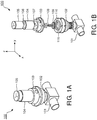
- Fig. 1A is perspective view of a valve 100 in accordance with a representative embodiment.
- the valve 100 is disposed over a connection 101 to a patient circuit (not shown in Fig. 1A ), and provides pressure relief in ways described below in connection with representative embodiments.
- the valve 100 comprises a lower housing 102, which is affixed to the connection 101.
- An intermediate housing 103 is connected between the lower housing 102 and an upper housing 104.
- the upper housing 104 contains an electromagnet, which comprises a coil 105.
- FIG. 1B is an exploded view of the valve depicted in Fig. 1A .
- the coil 105 is disposed around a magnet 106. Together, the coil 105 and the magnet 106 comprise an electromagnet.
- a shaft 107 is attached to the coil 105 through magnet 106 and extends through the intermediate housing 103.
- the shaft 107 is connected to a plunger 109 via a connector 108 as shown.
- the plunger 109 is seated in a diaphragm 110 and the diaphragm 110 is seated over an opening (not shown) in the connection 101.
- the coil 105 is driven in the positive and negative z-direction of the coordinate system shown in Fig. 1B by the application of current to the coil 105.
- the movement of the coil 105 results in movement of the shaft 107 in same z-direction, which in turn raises (+ z-direction) or lowers (- z-direction) the plunger 109 and in turn raises (+ z-direction) or lowers (- z-direction) the diaphragm 110.
- the diaphragm 110 is illustratively made of rubber, or a polymer material, or other suitable material.
- the diaphragm 110 comprises sidewalls 111 that allow the diaphragm 110 to be raised and lowered in response to forces applied to the plunger 109 by the electromagnet.
- the electromagnet provides a force through the plunger 109 to the diaphragm 110 that is commensurate with a desired pressure in the connection 101 and, therefore, the patient circuit.
- the magnitude and direction ( ⁇ z-direction) of the force provided by the diaphragm 110 is determined by the magnitude and direction of the current in the coil 105 determined by a controller (not shown in Fig. 1B ).
- a threshold pressure is set in the controller.
- the controller Based on feedback from a pressure transducer (not shown in Fig. 1B ), the controller changes the direction of the current in the coil 105 to raise the plunger 109 and the diaphragm 110 via the shaft 107.
- the raising of the diaphragm 110 allows air to be released from the connection 101 to the ambient through an opening (not shown) in the lower housing 102, or allows air to be provided to the connection 101 from the ambient through the opening in the lower housing 102.
- the diaphragm 110 is selectively raised and lowered to maintain the pressure in the patient circuit at a predetermined level set in the controller.
- the controller receives pressure data from the pressure transducer and raises the diaphragm 110 if the pressure in the patient circuit rises above the predetermined level, and lowers the diaphragm 110 if the pressure in the patient circuit falls below the predetermined level.
- the selective raising and lowering of the diaphragm 110 is in response to changes in the direction of current in the coil 105 based on signals from the controller.
- the valve 100 when operating as a safety valve, based on the forces applied to the diaphragm 110, the valve 100 can be set to relieve positive pressure or negative pressure based on a positive pressure threshold or a negative pressure threshold, respectively, set in the controller.
- the valve 100 can maintain the pressure in the patient circuit at a predetermined level through the selective raising and lowering of the diaphragm 110 to provide pressure relief.
- the ability to set the positive and negative pressure thresholds and to regulate the pressure in the patient circuit allows for a single component, valve 100, to provide the functions of a safety valve, a PPRV, and a NPRV.
- the ability to set the positive and negative pressure thresholds and to regulate the pressure in the patient circuit allows the valve 100 to be implemented in a variety of applications (e.g. neonatal ventilation, pediatric ventilation, and adult ventilation).
- FIG. 2 is a simplified schematic diagram of a ventilator 200 in accordance with a representative embodiment.
- the ventilator 200 may be configured to provide non-invasive ventilation or invasive ventilation.
- the ventilator 200 comprises an inhalation delivery system 201 and an exhalation system 202, which are connected to a patient 203 via a patient circuit 204 comprising a patient interface (not shown).
- Certain aspects of the inhalation delivery system 201, the exhalation system 202, the patient circuit 204 and the patient interface of the ventilator 200 are known.
- the inhalation delivery system 201, the exhalation system 202, the patient circuit 204 and the patient interface of the ventilator 200 of the ventilator 200 may be found, for example, in one of a variety of ventilators commercially available from Koninklijke Philips Electronics N.V., Eindhoven, The Netherlands.
- the ventilator 200 comprises the valve 100 illustratively provided between the inhalation delivery system 201 and the patient 203.
- a pressure transducer 205 is connected to the patient circuit 204 between the patient 203 and the valve 100.
- the pressure transducer 205 provides an electrical signal indicative of the pressure (pressure readings) in the patient circuit 204 between the patient 203 and the valve 100. As described more fully below, these pressure readings are used to raise the diaphragm 110 (opening the valve 100), or to lower the diaphragm (closing the valve 100), or to maintain the diaphragm 110 in its current position.
- the ventilator 200 comprises a controller 206, which receives the pressure readings from the pressure transducer 205, and provides commands to a valve driver 207.
- the valve driver 207 is illustratively a current amplifier/controller that provides a current in a particular direction and of a particular magnitude to the coil 105 of the valve 100 based on the commands from the controller 206.
- the magnitude and direction of the current through the coil 105 dictates the magnitude and direction of the force applied to the plunger 109 and thus to the diaphragm 110.
- the movement of the diaphragm 110 and the force applied by the diaphragm 110 provide pressure relief or pressure regulation of the air in the patient circuit 204 between the patient 203 and the valve 100.
- the controller 206 may be one of a variety of processing devices, such as a processor, microprocessor, or central processing unit (CPU), application specific integrated circuits (ASICs), field-programmable gate arrays (FPGAs), or combinations thereof, using software, firmware, hard-wired logic circuits, or combinations thereof.
- the controller 206 is a controller (e.g., microprocessor) of the ventilator 200.
- the controller 206 is a separate component from the ventilator 200.
- the controller 206, the pressure transducer 205 and the valve 100 comprise a stand-alone device that is connected to the patient circuit 204.
- a memory (not shown) is included for storing executable software/firmware and/or executable code for the controller 206.
- the executable software/firmware and/or executable code enables the determination of the pressure in the patient circuit 204 between the valve 100 and the patient 203 based on the data received from the pressure transducer.
- the executable software/firmware and/or executable code enable the determination by the controller 206 of the required magnitude and direction of the current to be supplied by valve driver 207 to the coil 105 of the valve 100.
- the memory may be any number, type and combination of nonvolatile read only memory (ROM) and volatile random access memory (RAM), and may store various types of information, such as computer programs and software algorithms executable by the processor or CPU.
- the memory may include any number, type and combination of tangible computer readable storage media, such as a disk drive, an electrically programmable read-only memory (EPROM), an electrically erasable and programmable read only memory (EEPROM), a CD, a DVD, a universal serial bus (USB) drive, and the like.
- a disk drive an electrically programmable read-only memory (EPROM), an electrically erasable and programmable read only memory (EEPROM), a CD, a DVD, a universal serial bus (USB) drive, and the like.
- EPROM electrically programmable read-only memory
- EEPROM electrically erasable and programmable read only memory
- CD compact disc
- DVD digital versatile disc
- USB universal serial bus
- the controller 206 provides commands to the valve driver 207 regarding the direction and magnitude of the current to be supplied to the coil based on pressure readings from the pressure transducer 205.
- the valve 100 is configured to provide pressure relief or pressure regulation based on the pressure readings received from the pressure transducer 205.
- a threshold limit (positive or negative) is set for a pressure in the patient circuit 204.
- the threshold limit is the maximum (positive or negative) pressure that can safely be provided to the patient 203. Pressure values above the threshold limit could be dangerous to the patient.
- the controller 206 upon receiving these data from the pressure transducer 205, the controller 206 provides a command to the valve driver 207 to reverse the direction of current flow in the coil 105 of the valve 100.
- the reversal of current flow causes the diaphragm 110 to be raised (+ z-direction in the coordinate system shown in Fig. 1B ).
- the threshold limit is a positive pressure, raising the diaphragm releases air to the ambient through the opening in the lower housing 102.
- the current to the coil 105 from the valve driver 207 is terminated based on commands from the controller 206.
- valve 100 functions as a safety valve.
- a desired pressure in the patient circuit 204 between the patient 203 and the valve 100 is set in the controller 206. If the pressure reading received by the controller 206 from the pressure transducer 205 indicates that the pressure is greater than the desired pressure (but less than a positive threshold pressure), the controller 206 provides commands to the valve driver 207 to terminate current flow in the coil 105 or to reverse current flow in the coil 105 causing the diaphragm 110 to be raised (+ z-direction in the coordinate system shown in Fig. 1B ) and air to be released to the ambient through the opening in the lower housing 102.
- the controller 206 provides commands to the valve driver 207 to provide current having a determined magnitude and direction to cause the diaphragm 110 to be lowered (- z-direction in the coordinate system shown in Fig. 1B ) and to provide a suitable force at the opening (not shown) to maintain the seal between the diaphragm 110 and the opening in the connection 101.
- the process of taking pressure readings and raising and lowering the diaphragm 110 as needed to regulate the pressure in the patient circuit 204 between the valve 100 and the patient 203 is iterative.
- the valve 100 functions as a positive pressure relief valve (PPRV).
- a desired pressure in the patient circuit 204 between the patient 203 and the valve 100 is set in the controller 206. If the data received by the controller 206 from the pressure transducer 205 indicate that the pressure is a negative pressure (but not equal to a negative threshold pressure), the controller 206 provides commands to terminate current flow in the coil 105 or to reverse current flow in the coil 105 causing the diaphragm 110 to be raised (+ z-direction in the coordinate system shown in Fig. 1B ) and air to be provided to the patient circuit 204 from the ambient through the opening in the lower housing 102.
- the controller 206 provides commands to resume current flow to cause the diaphragm 110 to be lowered (- z-direction in the coordinate system shown in Fig. 1B ) and to provide a force at the opening (not shown) sufficient to maintain the seal between the diaphragm 110 and the opening in the connection 101.
- the process of taking pressure measurements and raising and lowering the diaphragm 110 as needed to regulate the pressure in the patient circuit 204 between the valve 100 and the patient 203 is iterative.
- the valve 100 functions as a negative pressure relief valve (NPRV).
- valve 100 As an NPRV, consider the case where a patient 203 takes a "deep breath" with a magnitude so great that a blower (not shown) or other air source (not shown) in the inhalation delivery system 201 of the ventilator 200 could not provide a surge of air flow to the patient to satiate the breath required by the patient.
- the patient 203 will create a negative pressure to the patient circuit 204 between the patient 203 and the valve 100. This negative pressure is detected by the pressure transducer 205 and a pressure reading is provided to the controller 206.
- the controller 206 Based on the pressure reading, the controller 206 provides a command to the valve driver 207 to provide a current of magnitude and direction sufficient to raise the diaphragm and valve 100 will open to ambient through the opening in the lower housing 102.
- the pressure transducer 205 provides a subsequent pressure reading to the controller 206 and the pressure in the patient circuit 204 between the patient 203 and the valve 100 is maintained at the desired level through control of the diaphragm 110 of the valve 100.
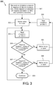
- Fig. 3 is a flow diagram of a method 300 of controlling a ventilation of a person in accordance with a representative embodiment.
- a computer readable medium having a computer readable program code embodied therein is stored in the memory accessible by the controller 206.
- the computer readable program code is adapted to be executed to implement the method through the controller 206.
- the method comprises setting an inhalation pressure limit at the controller 206.
- this inhalation pressure limit is either the positive pressure threshold for the patient circuit 204 between the valve 100 and the patient 203, or the negative pressure threshold for the patient circuit 204 between the valve 100 and the patient 203.
- both a positive pressure threshold and a negative pressure threshold can be set in the microprocessor.
- the inhalation pressure limit is the desired pressure in the patient circuit 204 between the patient 203 and the valve 100. It is emphasized that the valve 100 can be used as any of a safety valve, a PPRV and an NPRV.
- the inhalation pressure limit can have multiple settings: the positive pressure threshold, the negative pressure threshold, and the desired pressure in the patient circuit 204 between the patient 203 and the valve 100.
- the positive and negative thresholds are significantly greater in magnitude than the desired pressure in the patient circuit 204 between the patient 203 and the valve 100.
- the inhalation pressure limit may be adjusted for a particular application.
- the inhalation pressure limit can be set at a value useful in neonatal ventilation.
- the inhalation pressure limit can be set at a value useful in pediatric ventilation that is a greater pressure limit (positive or negative) than the inhalation pressure limit useful in neonatal ventilation.
- the inhalation pressure limit can be set at a value useful in adult ventilation that is a greater pressure limit (positive or negative) than the inhalation pressure limit useful in pediatric ventilation.
- these inhalation pressure limits are merely illustrative, and it is emphasized that a wide range of inhalation pressure limits can be provided at 301 to the controller 206.
- valve 100 is closed by lowering the diaphragm 110.
- current from the valve driver 207 is provided to the coil 105 and has a magnitude and direction determined by the controller 206 based on the desired pressure in the patient circuit 204 between the patient 203 and the valve 100.
- an inhalation pressure is read.
- a measurement of the pressure in the patient circuit 204 between the valve 100 and the patient 203 is made by the pressure transducer 205. This pressure reading is provided to the controller 206.
- the controller 206 compares the pressure reading from the pressure transducer 205 to a positive inhalation pressure limit stored in the memory. If the positive inhalation pressure limit is less than or equal to the pressure reading by the pressure transducer 205, the method 300 continues at 305. At 305, the controller 206 provides a command to raise the diaphragm 110 of the valve 100. Raising the diaphragm 110 allows air to be released to the ambient through the opening in the lower housing 102.
- valve 100 is closed by lowering the diaphragm 110.
- the magnitude and direction of the current from the valve driver 207 is determined by the controller 206 based on the pressure readings at 306 to lower the diaphragm 110 and to ensure a suitable force is applied by the plunger 109 to the diaphragm 110 to maintain the diaphragm 110 in a closed position.
- the valve 100 functions as a PPRV.
- the method 300 continues at 304.
- the controller 206 compares the pressure reading from the pressure transducer 205 to a positive inhalation pressure limit. If the positive inhalation pressure limit is greater than the pressure reading by the pressure transducer 205, the method 300 continues at 307.
- the controller 206 compares the pressure reading from the pressure transducer 205 to a negative inhalation pressure limit stored in the memory. If the negative inhalation pressure limit is less than or equal to (in magnitude) the pressure reading by the pressure transducer 205, the method 300 continues at 308.
- the controller 206 provides a command to raise the diaphragm 110 of the valve 100 to open the valve 100. Raising the diaphragm 110 allows for air from the ambient to be inhaled by the patient 203. As described above, the magnitude and direction of the current from the valve driver 207 is determined by the controller 206 based on the pressure readings at 307 to raise the diaphragm 110 with sufficient force to overcome the negative pressure in the patient circuit 204 between the patient 203 and the valve 100.
- the method 300 continues at 306 and another pressure measurement is made by the pressure transducer 205.
- the method 300 then continues at 302 and the valve 100 is closed by lowering the diaphragm 110.
- the magnitude and direction of the current from the valve driver 207 is determined by the controller 206 based on the pressure readings at 306 to lower the diaphragm 110 and to ensure a suitable force is applied by the plunger 109 to the diaphragm to maintain the diaphragm 110 in a closed position.
- the valve 100 functions as a PPRV.
- the method 300 continues at 309 and the method 300 repeats beginning at 303 with the valve 100 closed. If the desired pressure is set between the positive inhalation pressure limit and the negative inhalation pressure limit, the repetition of the method 300 allows for the regulation of the pressure in the patient circuit 204 between the patient 203 and the valve 100.
- the positive inhalation pressure limit is set to the positive pressure threshold. If the pressure measured by the pressure transducer 205 is greater than the positive inhalation pressure limit, at 305 the diaphragm 110 is raised to release air to the ambient.
- the negative pressure limit is set to the negative pressure threshold. If the pressure measured by the pressure transducer 205 is greater (in magnitude) than the negative inhalation pressure limit pressure limit, at 308 the diaphragm 110 is raised to receive air from the ambient.
- the valve 100 functions as a safety valve. After functioning as a safety valve (at 305 or 308), the method 300 continues at 306 and repeats as described above.
Landscapes
- Health & Medical Sciences (AREA)
- Engineering & Computer Science (AREA)
- Pulmonology (AREA)
- General Health & Medical Sciences (AREA)
- Veterinary Medicine (AREA)
- Heart & Thoracic Surgery (AREA)
- Hematology (AREA)
- Life Sciences & Earth Sciences (AREA)
- Animal Behavior & Ethology (AREA)
- Anesthesiology (AREA)
- Public Health (AREA)
- Emergency Medicine (AREA)
- Biomedical Technology (AREA)
- General Engineering & Computer Science (AREA)
- Mechanical Engineering (AREA)
- Business, Economics & Management (AREA)
- Emergency Management (AREA)
- Physics & Mathematics (AREA)
- Electromagnetism (AREA)
- Infusion, Injection, And Reservoir Apparatuses (AREA)
- Invalid Beds And Related Equipment (AREA)
- External Artificial Organs (AREA)
- Air Conditioning Control Device (AREA)
- Magnetically Actuated Valves (AREA)
Description
- Ventilators are used in a variety of applications to provide non-invasive (e.g., via a mask) and invasive (e.g., via an endotracheal tube) ventilation of a patient.
- A Safety Valve, Positive Pressure Relief Valve (PPRV) and Negative Pressure Relief Valve (NPRV) are components in a ventilator and are often required by standards applicable to ventilators. Normally in known ventilators, the safety valve, PPRV and NPRV are three separate parts and each provides a specific function. Notably, the safety valve ensures that the pressure in the patient circuit does not exceed a certain level; the PPRV allows for inhalation at a predetermined (positive) pressure; and the NPRV allows air from the ambient to be delivered to the patient when the negative pressure in the patient circuit exceeds a predetermined (negative) pressure (e.g., during ventilation system failure).
- Known safety valves, PPRVs and NPRVs are normally purely mechanical in nature. As such, a threshold pressure is set (e.g., by a spring mechanism) and cannot be varied to accommodate different patient requirements during ventilation. For example, the safety valve can only be set to a specific value for relieving pressure above the highest pressure level in the ventilator, and the NPRV can be set to a specific negative pressure level for relieving pressure below a lowest pressure level in the ventilator. Additionally, over time in known actuators, the accuracy of the valve can be diminished.
- What is needed is an apparatus and method for use in a ventilator that overcomes at least the shortcomings of the known apparatuses described above. Exemplary valves for use in a breathing apparatus are known from
US 2004/0069305 A1 ,WO 95/31241 A1 WO 2010/141983 A1 ,WO 2009/006932 A1 , and fromUS 5,265,594 A .US2004/0069305 discloses a ventilation system comprising an expiration valve, the expiration valve comprising an electromagnet, a shaft connected to the electromagnet, and a diaphragm connected to the shaft, wherein the electromagnet applies a force to the diaphragm - According to a first aspect of the present invention, a ventilation system according to claim 1 is provided.
- According to a second aspect of the present invention, a computer readable medium having a computer readable program code embodied therein is presented according to claim 7.
- The representative embodiments are best understood from the following detailed description when read with the accompanying drawing figures. The dimensions of features in the drawing figures may be arbitrarily increased or decreased for clarity of discussion. Wherever applicable and practical, like reference numerals refer to like elements.
-
FIG. 1A is perspective view of a valve in accordance with a representative embodiment. -
FIG. 1B is an exploded view of the valve depicted inFig. 1A . -
FIG. 2 is a simplified block diagram of a ventilation system in accordance with a representative embodiment. -
Fig. 3 is a flow diagram of a method of controlling a ventilation of a person in accordance with a representative embodiment. - In the following detailed description, for purposes of explanation and not limitation, representative embodiments disclosing specific details are set forth in order to provide a thorough understanding of embodiments according to the present teachings. However, it will be apparent to one having had the benefit of the present disclosure that other embodiments according to the present teachings that depart from the specific details disclosed herein remain within the scope of the appended claims. Moreover, descriptions of well-known devices and methods may be omitted so as not to obscure the description of the example embodiments. Such methods and devices are within the scope of the present teachings.
- Unless otherwise noted, when a first device is said to be connected to a second device, this encompasses cases where one or more intermediate devices may be employed to connect the two devices to each other. However, when a first device is said to be directly connected to a second device, this encompasses only cases where the two devices are connected to each other without any intermediate or intervening devices.
- In accordance with representative embodiments described below, a valve for use in a patient ventilation system is described. The valve functions as a safety valve, a PPRV and an NPRV and provides these functions as a single component. The valves of the representative embodiments are contemplated for use in non-invasive ventilation systems and in invasive ventilation systems.
-
Fig. 1A is perspective view of avalve 100 in accordance with a representative embodiment. Thevalve 100 is disposed over aconnection 101 to a patient circuit (not shown inFig. 1A ), and provides pressure relief in ways described below in connection with representative embodiments. Thevalve 100 comprises alower housing 102, which is affixed to theconnection 101. Anintermediate housing 103 is connected between thelower housing 102 and anupper housing 104. As described more fully below, theupper housing 104 contains an electromagnet, which comprises acoil 105. -
FIG. 1B is an exploded view of the valve depicted inFig. 1A . Thecoil 105 is disposed around amagnet 106. Together, thecoil 105 and themagnet 106 comprise an electromagnet. Ashaft 107 is attached to thecoil 105 throughmagnet 106 and extends through theintermediate housing 103. Theshaft 107 is connected to aplunger 109 via aconnector 108 as shown. Theplunger 109 is seated in adiaphragm 110 and thediaphragm 110 is seated over an opening (not shown) in theconnection 101. As described more fully below, thecoil 105 is driven in the positive and negative z-direction of the coordinate system shown inFig. 1B by the application of current to thecoil 105. The movement of thecoil 105 results in movement of theshaft 107 in same z-direction, which in turn raises (+ z-direction) or lowers (- z-direction) theplunger 109 and in turn raises (+ z-direction) or lowers (- z-direction) thediaphragm 110. - The
diaphragm 110 is illustratively made of rubber, or a polymer material, or other suitable material. Thediaphragm 110 comprisessidewalls 111 that allow thediaphragm 110 to be raised and lowered in response to forces applied to theplunger 109 by the electromagnet. In accordance with representative embodiments, the electromagnet provides a force through theplunger 109 to thediaphragm 110 that is commensurate with a desired pressure in theconnection 101 and, therefore, the patient circuit. - As described more fully below, the magnitude and direction (± z-direction) of the force provided by the
diaphragm 110 is determined by the magnitude and direction of the current in thecoil 105 determined by a controller (not shown inFig. 1B ). In certain embodiments, a threshold pressure is set in the controller. Based on feedback from a pressure transducer (not shown inFig. 1B ), the controller changes the direction of the current in thecoil 105 to raise theplunger 109 and thediaphragm 110 via theshaft 107. The raising of thediaphragm 110 allows air to be released from theconnection 101 to the ambient through an opening (not shown) in thelower housing 102, or allows air to be provided to theconnection 101 from the ambient through the opening in thelower housing 102. In other embodiments, thediaphragm 110 is selectively raised and lowered to maintain the pressure in the patient circuit at a predetermined level set in the controller. The controller receives pressure data from the pressure transducer and raises thediaphragm 110 if the pressure in the patient circuit rises above the predetermined level, and lowers thediaphragm 110 if the pressure in the patient circuit falls below the predetermined level. The selective raising and lowering of thediaphragm 110 is in response to changes in the direction of current in thecoil 105 based on signals from the controller. - Beneficially, when operating as a safety valve, based on the forces applied to the
diaphragm 110, thevalve 100 can be set to relieve positive pressure or negative pressure based on a positive pressure threshold or a negative pressure threshold, respectively, set in the controller. When operating as a pressure regulator, thevalve 100 can maintain the pressure in the patient circuit at a predetermined level through the selective raising and lowering of thediaphragm 110 to provide pressure relief. The ability to set the positive and negative pressure thresholds and to regulate the pressure in the patient circuit allows for a single component,valve 100, to provide the functions of a safety valve, a PPRV, and a NPRV. Moreover, the ability to set the positive and negative pressure thresholds and to regulate the pressure in the patient circuit allows thevalve 100 to be implemented in a variety of applications (e.g. neonatal ventilation, pediatric ventilation, and adult ventilation). -
FIG. 2 is a simplified schematic diagram of aventilator 200 in accordance with a representative embodiment. Theventilator 200 may be configured to provide non-invasive ventilation or invasive ventilation. Theventilator 200 comprises aninhalation delivery system 201 and anexhalation system 202, which are connected to apatient 203 via apatient circuit 204 comprising a patient interface (not shown). Certain aspects of theinhalation delivery system 201, theexhalation system 202, thepatient circuit 204 and the patient interface of theventilator 200 are known. For example, theinhalation delivery system 201, theexhalation system 202, thepatient circuit 204 and the patient interface of theventilator 200 of theventilator 200 may be found, for example, in one of a variety of ventilators commercially available from Koninklijke Philips Electronics N.V., Eindhoven, The Netherlands. - The
ventilator 200 comprises thevalve 100 illustratively provided between theinhalation delivery system 201 and thepatient 203. Apressure transducer 205 is connected to thepatient circuit 204 between the patient 203 and thevalve 100. Thepressure transducer 205 provides an electrical signal indicative of the pressure (pressure readings) in thepatient circuit 204 between the patient 203 and thevalve 100. As described more fully below, these pressure readings are used to raise the diaphragm 110 (opening the valve 100), or to lower the diaphragm (closing the valve 100), or to maintain thediaphragm 110 in its current position. - The
ventilator 200 comprises acontroller 206, which receives the pressure readings from thepressure transducer 205, and provides commands to avalve driver 207. Thevalve driver 207 is illustratively a current amplifier/controller that provides a current in a particular direction and of a particular magnitude to thecoil 105 of thevalve 100 based on the commands from thecontroller 206. As described above, the magnitude and direction of the current through thecoil 105 dictates the magnitude and direction of the force applied to theplunger 109 and thus to thediaphragm 110. As described more fully below, the movement of thediaphragm 110 and the force applied by thediaphragm 110 provide pressure relief or pressure regulation of the air in thepatient circuit 204 between the patient 203 and thevalve 100. - The
controller 206 may be one of a variety of processing devices, such as a processor, microprocessor, or central processing unit (CPU), application specific integrated circuits (ASICs), field-programmable gate arrays (FPGAs), or combinations thereof, using software, firmware, hard-wired logic circuits, or combinations thereof. In a representative embodiment, thecontroller 206 is a controller (e.g., microprocessor) of theventilator 200. In another embodiment, thecontroller 206 is a separate component from theventilator 200. In such an embodiment, thecontroller 206, thepressure transducer 205 and thevalve 100 comprise a stand-alone device that is connected to thepatient circuit 204. - A memory (not shown) is included for storing executable software/firmware and/or executable code for the
controller 206. The executable software/firmware and/or executable code enables the determination of the pressure in thepatient circuit 204 between thevalve 100 and thepatient 203 based on the data received from the pressure transducer. The executable software/firmware and/or executable code enable the determination by thecontroller 206 of the required magnitude and direction of the current to be supplied byvalve driver 207 to thecoil 105 of thevalve 100. The memory may be any number, type and combination of nonvolatile read only memory (ROM) and volatile random access memory (RAM), and may store various types of information, such as computer programs and software algorithms executable by the processor or CPU. The memory may include any number, type and combination of tangible computer readable storage media, such as a disk drive, an electrically programmable read-only memory (EPROM), an electrically erasable and programmable read only memory (EEPROM), a CD, a DVD, a universal serial bus (USB) drive, and the like. - As described above, the
controller 206 provides commands to thevalve driver 207 regarding the direction and magnitude of the current to be supplied to the coil based on pressure readings from thepressure transducer 205. In response, thevalve 100 is configured to provide pressure relief or pressure regulation based on the pressure readings received from thepressure transducer 205. In one example, a threshold limit (positive or negative) is set for a pressure in thepatient circuit 204. The threshold limit is the maximum (positive or negative) pressure that can safely be provided to thepatient 203. Pressure values above the threshold limit could be dangerous to the patient. For example, if the pressure measured by thepressure transducer 205 exceeds the threshold limit, upon receiving these data from thepressure transducer 205, thecontroller 206 provides a command to thevalve driver 207 to reverse the direction of current flow in thecoil 105 of thevalve 100. The reversal of current flow causes thediaphragm 110 to be raised (+ z-direction in the coordinate system shown inFig. 1B ). If the threshold limit is a positive pressure, raising the diaphragm releases air to the ambient through the opening in thelower housing 102. In another embodiment, rather than reversing the direction of current flow, the current to thecoil 105 from thevalve driver 207 is terminated based on commands from thecontroller 206. With no current in thecoil 105, no force is applied by theplunger 109 to thediaphragm 110. This results in the raising of thediaphragm 110 and the release of air to the ambient through the opening in thelower housing 102. As should be appreciated, in this example, thevalve 100 functions as a safety valve. - In another example, a desired pressure in the
patient circuit 204 between the patient 203 and thevalve 100 is set in thecontroller 206. If the pressure reading received by thecontroller 206 from thepressure transducer 205 indicates that the pressure is greater than the desired pressure (but less than a positive threshold pressure), thecontroller 206 provides commands to thevalve driver 207 to terminate current flow in thecoil 105 or to reverse current flow in thecoil 105 causing thediaphragm 110 to be raised (+ z-direction in the coordinate system shown inFig. 1B ) and air to be released to the ambient through the opening in thelower housing 102. If the next measurement data from thepressure transducer 205 indicates that the pressure in thepatient circuit 204 between thevalve 100 and thepatient 203 is at or below the desired pressure, thecontroller 206 provides commands to thevalve driver 207 to provide current having a determined magnitude and direction to cause thediaphragm 110 to be lowered (- z-direction in the coordinate system shown inFig. 1B ) and to provide a suitable force at the opening (not shown) to maintain the seal between thediaphragm 110 and the opening in theconnection 101. As described below in connection with a representative embodiment, the process of taking pressure readings and raising and lowering thediaphragm 110 as needed to regulate the pressure in thepatient circuit 204 between thevalve 100 and thepatient 203 is iterative. As should be appreciated, in this example, thevalve 100 functions as a positive pressure relief valve (PPRV). - In another example, a desired pressure in the
patient circuit 204 between the patient 203 and thevalve 100 is set in thecontroller 206. If the data received by thecontroller 206 from thepressure transducer 205 indicate that the pressure is a negative pressure (but not equal to a negative threshold pressure), thecontroller 206 provides commands to terminate current flow in thecoil 105 or to reverse current flow in thecoil 105 causing thediaphragm 110 to be raised (+ z-direction in the coordinate system shown inFig. 1B ) and air to be provided to thepatient circuit 204 from the ambient through the opening in thelower housing 102. If the next measurement data from thepressure transducer 205 indicates that the pressure in thepatient circuit 204 between thevalve 100 and thepatient 203 is no longer at the negative pressure, thecontroller 206 provides commands to resume current flow to cause thediaphragm 110 to be lowered (- z-direction in the coordinate system shown inFig. 1B ) and to provide a force at the opening (not shown) sufficient to maintain the seal between thediaphragm 110 and the opening in theconnection 101. As described below in connection with a representative embodiment, the process of taking pressure measurements and raising and lowering thediaphragm 110 as needed to regulate the pressure in thepatient circuit 204 between thevalve 100 and thepatient 203 is iterative. As should be appreciated, in this example, thevalve 100 functions as a negative pressure relief valve (NPRV). - By way of illustration of the use of
valve 100 as an NPRV, consider the case where apatient 203 takes a "deep breath" with a magnitude so great that a blower (not shown) or other air source (not shown) in theinhalation delivery system 201 of theventilator 200 could not provide a surge of air flow to the patient to satiate the breath required by the patient. In this case, thepatient 203 will create a negative pressure to thepatient circuit 204 between the patient 203 and thevalve 100. This negative pressure is detected by thepressure transducer 205 and a pressure reading is provided to thecontroller 206. Based on the pressure reading, thecontroller 206 provides a command to thevalve driver 207 to provide a current of magnitude and direction sufficient to raise the diaphragm andvalve 100 will open to ambient through the opening in thelower housing 102. Thepressure transducer 205 provides a subsequent pressure reading to thecontroller 206 and the pressure in thepatient circuit 204 between the patient 203 and thevalve 100 is maintained at the desired level through control of thediaphragm 110 of thevalve 100. -
Fig. 3 is a flow diagram of amethod 300 of controlling a ventilation of a person in accordance with a representative embodiment. A computer readable medium having a computer readable program code embodied therein is stored in the memory accessible by thecontroller 206. The computer readable program code is adapted to be executed to implement the method through thecontroller 206. - At 301 the method comprises setting an inhalation pressure limit at the
controller 206. In an embodiment where thevalve 100 is functioning as a safety valve this inhalation pressure limit is either the positive pressure threshold for thepatient circuit 204 between thevalve 100 and thepatient 203, or the negative pressure threshold for thepatient circuit 204 between thevalve 100 and thepatient 203. As should be appreciated, both a positive pressure threshold and a negative pressure threshold can be set in the microprocessor. In embodiments where thevalve 100 functions as a PPRV or as an NPRV, the inhalation pressure limit is the desired pressure in thepatient circuit 204 between the patient 203 and thevalve 100. It is emphasized that thevalve 100 can be used as any of a safety valve, a PPRV and an NPRV. As such, the inhalation pressure limit can have multiple settings: the positive pressure threshold, the negative pressure threshold, and the desired pressure in thepatient circuit 204 between the patient 203 and thevalve 100. As should be appreciated, the positive and negative thresholds are significantly greater in magnitude than the desired pressure in thepatient circuit 204 between the patient 203 and thevalve 100. - Beneficially, the inhalation pressure limit may be adjusted for a particular application. For example, the inhalation pressure limit can be set at a value useful in neonatal ventilation. The inhalation pressure limit can be set at a value useful in pediatric ventilation that is a greater pressure limit (positive or negative) than the inhalation pressure limit useful in neonatal ventilation. Additionally, the inhalation pressure limit can be set at a value useful in adult ventilation that is a greater pressure limit (positive or negative) than the inhalation pressure limit useful in pediatric ventilation. Notably, these inhalation pressure limits are merely illustrative, and it is emphasized that a wide range of inhalation pressure limits can be provided at 301 to the
controller 206. - At 302 the
valve 100 is closed by lowering thediaphragm 110. As described above, current from thevalve driver 207 is provided to thecoil 105 and has a magnitude and direction determined by thecontroller 206 based on the desired pressure in thepatient circuit 204 between the patient 203 and thevalve 100. - At 303 an inhalation pressure is read. In a representative embodiment, a measurement of the pressure in the
patient circuit 204 between thevalve 100 and thepatient 203 is made by thepressure transducer 205. This pressure reading is provided to thecontroller 206. - The
controller 206 compares the pressure reading from thepressure transducer 205 to a positive inhalation pressure limit stored in the memory. If the positive inhalation pressure limit is less than or equal to the pressure reading by thepressure transducer 205, themethod 300 continues at 305. At 305, thecontroller 206 provides a command to raise thediaphragm 110 of thevalve 100. Raising thediaphragm 110 allows air to be released to the ambient through the opening in thelower housing 102. - At 306 another pressure measurement is made by the
pressure transducer 205. Themethod 300 continues at 302 and thevalve 100 is closed by lowering thediaphragm 110. As described above, the magnitude and direction of the current from thevalve driver 207 is determined by thecontroller 206 based on the pressure readings at 306 to lower thediaphragm 110 and to ensure a suitable force is applied by theplunger 109 to thediaphragm 110 to maintain thediaphragm 110 in a closed position. When the inhalation limit is set to a desired positive pressure, thevalve 100 functions as a PPRV. - The
method 300 continues at 304. Thecontroller 206 compares the pressure reading from thepressure transducer 205 to a positive inhalation pressure limit. If the positive inhalation pressure limit is greater than the pressure reading by thepressure transducer 205, themethod 300 continues at 307. - At 307, the
controller 206 compares the pressure reading from thepressure transducer 205 to a negative inhalation pressure limit stored in the memory. If the negative inhalation pressure limit is less than or equal to (in magnitude) the pressure reading by thepressure transducer 205, themethod 300 continues at 308. - At 308, the
controller 206 provides a command to raise thediaphragm 110 of thevalve 100 to open thevalve 100. Raising thediaphragm 110 allows for air from the ambient to be inhaled by thepatient 203. As described above, the magnitude and direction of the current from thevalve driver 207 is determined by thecontroller 206 based on the pressure readings at 307 to raise thediaphragm 110 with sufficient force to overcome the negative pressure in thepatient circuit 204 between the patient 203 and thevalve 100. - After the
valve 100 is opened, themethod 300 continues at 306 and another pressure measurement is made by thepressure transducer 205. Themethod 300 then continues at 302 and thevalve 100 is closed by lowering thediaphragm 110. As described above, the magnitude and direction of the current from thevalve driver 207 is determined by thecontroller 206 based on the pressure readings at 306 to lower thediaphragm 110 and to ensure a suitable force is applied by theplunger 109 to the diaphragm to maintain thediaphragm 110 in a closed position. When the inhalation limit is set to a desired positive pressure, thevalve 100 functions as a PPRV. - If at 307 the negative inhalation pressure limit is greater (in magnitude) than pressure reading by the
pressure transducer 205, themethod 300 continues at 309 and themethod 300 repeats beginning at 303 with thevalve 100 closed. If the desired pressure is set between the positive inhalation pressure limit and the negative inhalation pressure limit, the repetition of themethod 300 allows for the regulation of the pressure in thepatient circuit 204 between the patient 203 and thevalve 100. - In an embodiment, the positive inhalation pressure limit is set to the positive pressure threshold. If the pressure measured by the
pressure transducer 205 is greater than the positive inhalation pressure limit, at 305 thediaphragm 110 is raised to release air to the ambient. In another embodiment, the negative pressure limit is set to the negative pressure threshold. If the pressure measured by thepressure transducer 205 is greater (in magnitude) than the negative inhalation pressure limit pressure limit, at 308 thediaphragm 110 is raised to receive air from the ambient. In embodiments where the positive inhalation pressure limit is set to the positive pressure threshold, or the negative inhalation pressure limit is set to the negative pressure threshold, thevalve 100 functions as a safety valve. After functioning as a safety valve (at 305 or 308), themethod 300 continues at 306 and repeats as described above. - While representative embodiments are disclosed herein, one of ordinary skill in the art appreciates that many variations that are in accordance with the present teachings are possible and remain within the scope of the appended claims. The invention therefore is not to be restricted except within the scope of the appended claims.
Claims (8)
- A ventilation system (200), comprising:a ventilator connected to a patient circuit (204);a pressure transducer (205) configured to determine a pressure in the patient circuit (204) and to provide an electrical signal indicative of the pressure in the patient circuit (204);a valve (100) which is connected to the patient circuit (204) via a connection (101) and which is configured to control the pressure in the ventilation system (200), the valve comprising: an electromagnet (105, 106), a shaft (107) connected to the electromagnet (105, 106), and a diaphragm (110) connected to the shaft (107);a controller (206) which is connected to the valve (100) and configured to receive the electrical signal from the pressure transducer (205); anda valve driver (207) that is configured to receive commands of the controller (206) and to provide a current to the electromagnet (105, 106) of the valve (100) based on the commands of the controller (206),wherein the controller (206) is configured to provide the commands to the valve driver (207) based on the electrical signal, and wherein the electromagnet (105, 106) applies a force to the diaphragm (110) based on the current provided by the valve driver (207),characterized in that the controller (206) is configured to control the valve driver (207) to control the electromagnet (105, 106):- to raise the diaphragm (110) of the valve (100) to allow air to be released to the ambient through an opening in the connection (101) to the patient circuit (204) if the pressure in the patient circuit (204) is above a positive pressure threshold, and- to raise the diaphragm (110) of the valve (100) to allow air to be provided from the ambient through the opening in the connection (101) if the pressure in the patient circuit (204) is below a negative pressure threshold.
- A ventilation system as claimed in claim 1, wherein the valve (100) further comprises a plunger (109) connected between the diaphragm (110) and the shaft (107), wherein the plunger (109) is configured to raise and lower the diaphragm (110) based on the force provided by the electromagnet (105, 106).
- A ventilation system as claimed in claim 1, wherein the electromagnet comprises a coil (105) disposed around a magnet (106).
- A ventilation system as claimed in claim 3, wherein the shaft (107) is provided through the magnet (106).
- A ventilation system as claimed in claim 1, wherein the diaphragm (110) is configured to release pressure from the patient circuit (204) of the ventilation system (200) when the controller (206) controls the valve driver (207) to provide no current to the electromagnet (105, 106).
- A ventilation system as claimed in claim 1, wherein the diaphragm (110) is configured to maintain a selected pressure in the patient circuit (204) of the ventilation system (200) based on a current provided to the electromagnet (105, 106).
- A computer readable medium having a computer readable program code embodied therein, the computer readable program code adapted to be executed to implement a method of controlling a valve (100) within a ventilation system (200) according to claim 1, the method comprising the steps of:receiving an electrical signal indicative of a pressure in a patient circuit (204);providing a positive pressure threshold;providing a negative pressure threshold;providing based on the electrical signal commands to a valve driver (207) to drive the valve (100) by providing a current to an electromagnet (105, 106) comprised in the valve (100), wherein the valve (100) is connected to the patient circuit (204) via a connection (101) and further comprises a shaft (107) connected to the electromagnet (105, 106), and a diaphragm (110) connected to the shaft (107), so that the electromagnet (105, 106) applies a force to the diaphragm (110) based on the current provided by the valve driver (207),characterized in the steps of:providing commands to the valve driver (207) to control the electromagnet (105, 106) to raise the diaphragm of the valve to allow air to be released to the ambient through an opening in the connection if the pressure in the patient circuit (204) is above the positive pressure threshold, andproviding commands to the valve driver (207) to control the electromagnet (105, 106) to raise the diaphragm of the valve to allow air to be provided from the ambient through the opening in the connection if the pressure in the patient circuit (204) is below the negative pressure threshold.
- A computer readable medium as claimed in claim 7, further comprising maintaining the valve (100) in a closed position when the pressure is between the negative pressure threshold and the positive pressure threshold.
Applications Claiming Priority (2)
| Application Number | Priority Date | Filing Date | Title |
|---|---|---|---|
| US201061425515P | 2010-12-21 | 2010-12-21 | |
| PCT/IB2011/055574 WO2012085740A1 (en) | 2010-12-21 | 2011-12-09 | Active valve for ventilators |
Publications (2)
| Publication Number | Publication Date |
|---|---|
| EP2654871A1 EP2654871A1 (en) | 2013-10-30 |
| EP2654871B1 true EP2654871B1 (en) | 2017-05-17 |
Family
ID=45446127
Family Applications (1)
| Application Number | Title | Priority Date | Filing Date |
|---|---|---|---|
| EP11805221.6A Active EP2654871B1 (en) | 2010-12-21 | 2011-12-09 | Ventilator with active valve |
Country Status (7)
| Country | Link |
|---|---|
| US (2) | US9656040B2 (en) |
| EP (1) | EP2654871B1 (en) |
| JP (1) | JP6356966B2 (en) |
| CN (1) | CN103391795B (en) |
| BR (1) | BR112013015388B1 (en) |
| RU (1) | RU2595479C2 (en) |
| WO (1) | WO2012085740A1 (en) |
Families Citing this family (6)
| Publication number | Priority date | Publication date | Assignee | Title |
|---|---|---|---|---|
| US9757528B2 (en) * | 2010-08-23 | 2017-09-12 | Darren Rubin | Nebulizer having different negative pressure threshold settings |
| GR1008255B (en) * | 2013-03-22 | 2014-07-21 | Γεωργιος Δημητριου Ναουμ | Nebulizer and inhalation mask |
| CN106139338A (en) * | 2015-03-16 | 2016-11-23 | 孟海侠 | Lung ventilator |
| RU2735638C1 (en) * | 2020-06-02 | 2020-11-05 | Игорь Георгиевич Киселев | Automatic system of artificial lung ventilation |
| RU2749760C1 (en) * | 2020-11-27 | 2021-06-16 | Игорь Георгиевич Киселев | Automatic system for artificial lung ventilation |
| KR102873842B1 (en) * | 2023-12-29 | 2025-10-20 | 주식회사 소연메디칼 | Breathing gas leak valve device for ventilator |
Family Cites Families (29)
| Publication number | Priority date | Publication date | Assignee | Title |
|---|---|---|---|---|
| US3976064A (en) * | 1975-03-11 | 1976-08-24 | Wood William W | Intermittent mandatory assisted ventilation system for positive pressure breathing apparatus |
| US4502481A (en) * | 1983-02-15 | 1985-03-05 | Christian Pamela H | Device for manually ventilating a patient |
| DE8322570U1 (en) * | 1983-08-05 | 1985-01-17 | Robert Bosch Gmbh, 7000 Stuttgart | PRESSURE REGULATOR |
| JPS6212348U (en) | 1985-07-04 | 1987-01-26 | ||
| US4951661A (en) | 1988-06-08 | 1990-08-28 | Thayer Medical Corporation | Quick-connect adapter valve for connecting nebulizer and fluid ventilator hose |
| US5127400A (en) * | 1990-03-23 | 1992-07-07 | Bird Products Corp. | Ventilator exhalation valve |
| EP0483401B1 (en) * | 1990-10-30 | 1994-10-05 | Siemens-Elema AB | Device, e.g. a lung ventilator, for controlling a fluid flow, particularly a gas flow |
| JP2921976B2 (en) | 1990-11-30 | 1999-07-19 | アイ・エム・アイ株式会社 | Expiratory valve device in ventilator |
| SE504052C2 (en) | 1994-05-13 | 1996-10-28 | Engstrom Medical Ab | Control valve for controlling a fluid |
| US5632270A (en) * | 1994-09-12 | 1997-05-27 | Puritan-Bennett Corporation | Method and apparatus for control of lung ventilator exhalation circuit |
| US5596984A (en) * | 1994-09-12 | 1997-01-28 | Puritan-Bennett Corporation | Lung ventilator safety circuit |
| ATE252403T1 (en) * | 1994-10-14 | 2003-11-15 | Bird Products Corp | EXHAUST VALVE |
| JPH10179742A (en) * | 1996-12-25 | 1998-07-07 | Sumitomo Seika Chem Co Ltd | Portable nitrogen monoxide-gaseous oxygen supply device and its operation |
| US5791339A (en) * | 1997-03-13 | 1998-08-11 | Nellcor Puritan Bennettt Incorprated | Spring piloted safety valve with jet venturi bias |
| SE9704660D0 (en) | 1997-12-15 | 1997-12-15 | Siemens Elema Ab | Valve for regulating a gas flow |
| JP2000014784A (en) | 1998-07-02 | 2000-01-18 | Instrumentarium Oy | Auxiliary respiration ventilator and safety valve of patient conduit of auxiliary respiration apparatus |
| RU2146536C1 (en) * | 1999-04-16 | 2000-03-20 | Специальное конструкторское бюро экспериментального оборудования при Государственном научном центре Российской Федерации "Институт медико-биологических проблем" | Method for preparation and supply of therapeutic gas mix and device for its embodiment |
| US7246618B2 (en) * | 2001-06-21 | 2007-07-24 | Nader Maher Habashi | Ventilation method and control of a ventilator based on same |
| US6910674B2 (en) | 2002-10-09 | 2005-06-28 | Maquet Critical Care Ab | Valve for use in a breathing apparatus |
| US7152597B2 (en) * | 2003-09-25 | 2006-12-26 | Datex-Ohmeda, Inc. | Breathing circuit adapter |
| US20080078389A1 (en) * | 2006-09-29 | 2008-04-03 | Yang Xiao | Heliox delivery system and method with positive pressure support |
| DE102007016725B3 (en) * | 2007-04-07 | 2008-01-17 | Dräger Medical AG & Co. KG | Electrodynamic drive for metering valve, comprises annular gap arranged between magnetic field source and housing, where moving coil with push rod is axially adjusted in gap, and measuring coil is provided within inference covering |
| CN101310792A (en) * | 2007-06-28 | 2008-11-26 | 北京谊安医疗系统股份有限公司 | Device and method for controlling expiratory valve |
| WO2009006932A1 (en) * | 2007-07-06 | 2009-01-15 | Maquet Critical Care Ab | Expiratory valve of an anesthetic breathing apparatus having safety backup |
| DE102008017339A1 (en) * | 2008-04-04 | 2009-10-08 | Linde Aktiengesellschaft | Gas e.g. oxygen, supplying device for use during e.g. non-invasive breathing of spontaneously breathing patient in hospital, has control unit controlling flowrate regulating unit based determined flow rate |
| US20100224191A1 (en) | 2009-03-06 | 2010-09-09 | Cardinal Health 207, Inc. | Automated Oxygen Delivery System |
| CN101856354A (en) | 2009-04-09 | 2010-10-13 | 北京京卫燕康药物研究所有限公司 | Novel composition for reducing blood sugar |
| US9923442B2 (en) * | 2009-06-09 | 2018-03-20 | Resmed Limited | Breathing assistance device with linear actuated gas regulating valve |
| CN101856534B (en) * | 2010-02-03 | 2013-08-14 | 苏州凯迪泰医学科技有限公司 | Three-way pressure balance valve and medical respirator |
-
2011
- 2011-12-09 EP EP11805221.6A patent/EP2654871B1/en active Active
- 2011-12-09 BR BR112013015388-1A patent/BR112013015388B1/en active IP Right Grant
- 2011-12-09 RU RU2013133937/14A patent/RU2595479C2/en not_active IP Right Cessation
- 2011-12-09 WO PCT/IB2011/055574 patent/WO2012085740A1/en not_active Ceased
- 2011-12-09 CN CN201180068036.8A patent/CN103391795B/en active Active
- 2011-12-09 US US13/994,847 patent/US9656040B2/en active Active
- 2011-12-09 JP JP2013545547A patent/JP6356966B2/en active Active
-
2017
- 2017-04-20 US US15/492,019 patent/US10589053B2/en active Active
Also Published As
| Publication number | Publication date |
|---|---|
| JP2014502893A (en) | 2014-02-06 |
| BR112013015388B1 (en) | 2021-01-12 |
| BR112013015388A2 (en) | 2017-09-12 |
| RU2595479C2 (en) | 2016-08-27 |
| RU2013133937A (en) | 2015-01-27 |
| EP2654871A1 (en) | 2013-10-30 |
| CN103391795A (en) | 2013-11-13 |
| US20170216553A1 (en) | 2017-08-03 |
| US9656040B2 (en) | 2017-05-23 |
| CN103391795B (en) | 2016-01-13 |
| JP6356966B2 (en) | 2018-07-11 |
| BR112013015388A8 (en) | 2018-02-06 |
| WO2012085740A1 (en) | 2012-06-28 |
| US20130276903A1 (en) | 2013-10-24 |
| US10589053B2 (en) | 2020-03-17 |
Similar Documents
| Publication | Publication Date | Title |
|---|---|---|
| US10589053B2 (en) | Active valve for ventilators | |
| CA2825832C (en) | Pressure relief device and system | |
| AU2006200685B2 (en) | Pressure relief valve | |
| AU2012211062A1 (en) | Pressure relief device and system | |
| WO2019094561A1 (en) | Medical ventilator system and method for providing respiratory support to a patient | |
| JP2023106544A (en) | Ventilator for high-flow oxygen therapy | |
| US10874808B2 (en) | Pressure control in respiratory treatment apparatus | |
| US20150147956A1 (en) | Control means of central flow system and central flow system | |
| US20120103336A1 (en) | Ventilator System and Method | |
| US9808607B2 (en) | System and method for determining position and pressure of an implantable shunt | |
| TWI630578B (en) | Member quantity control system and member quantity control method | |
| CN108954699A (en) | A kind of operation of air conditioner frequency adjustment method and air-conditioning system | |
| JP2022143893A (en) | Valve module, valve control program and valve control method | |
| JP7678216B2 (en) | Insufflation device safety valve with electrically variable cracking pressure | |
| CN105843268A (en) | Valve positioner with overvoltage protection capability | |
| FR3051117A3 (en) | RAPID ADAPTATION OF FAN PARAMETERS TO INTERFACE TYPE | |
| CN204784894U (en) | Safety valve |
Legal Events
| Date | Code | Title | Description |
|---|---|---|---|
| PUAI | Public reference made under article 153(3) epc to a published international application that has entered the european phase |
Free format text: ORIGINAL CODE: 0009012 |
|
| 17P | Request for examination filed |
Effective date: 20130722 |
|
| AK | Designated contracting states |
Kind code of ref document: A1 Designated state(s): AL AT BE BG CH CY CZ DE DK EE ES FI FR GB GR HR HU IE IS IT LI LT LU LV MC MK MT NL NO PL PT RO RS SE SI SK SM TR |
|
| DAX | Request for extension of the european patent (deleted) | ||
| 17Q | First examination report despatched |
Effective date: 20160525 |
|
| GRAP | Despatch of communication of intention to grant a patent |
Free format text: ORIGINAL CODE: EPIDOSNIGR1 |
|
| INTG | Intention to grant announced |
Effective date: 20161215 |
|
| RIN1 | Information on inventor provided before grant (corrected) |
Inventor name: AHMAD, SAMIR Inventor name: ARCILLA, MABINI Inventor name: KELLY, EAMONN |
|
| GRAS | Grant fee paid |
Free format text: ORIGINAL CODE: EPIDOSNIGR3 |
|
| GRAA | (expected) grant |
Free format text: ORIGINAL CODE: 0009210 |
|
| AK | Designated contracting states |
Kind code of ref document: B1 Designated state(s): AL AT BE BG CH CY CZ DE DK EE ES FI FR GB GR HR HU IE IS IT LI LT LU LV MC MK MT NL NO PL PT RO RS SE SI SK SM TR |
|
| REG | Reference to a national code |
Ref country code: GB Ref legal event code: FG4D |
|
| REG | Reference to a national code |
Ref country code: CH Ref legal event code: EP |
|
| REG | Reference to a national code |
Ref country code: IE Ref legal event code: FG4D |
|
| REG | Reference to a national code |
Ref country code: AT Ref legal event code: REF Ref document number: 893915 Country of ref document: AT Kind code of ref document: T Effective date: 20170615 |
|
| REG | Reference to a national code |
Ref country code: DE Ref legal event code: R096 Ref document number: 602011038104 Country of ref document: DE |
|
| REG | Reference to a national code |
Ref country code: NL Ref legal event code: MP Effective date: 20170517 |
|
| REG | Reference to a national code |
Ref country code: LT Ref legal event code: MG4D |
|
| REG | Reference to a national code |
Ref country code: AT Ref legal event code: MK05 Ref document number: 893915 Country of ref document: AT Kind code of ref document: T Effective date: 20170517 |
|
| PG25 | Lapsed in a contracting state [announced via postgrant information from national office to epo] |
Ref country code: FI Free format text: LAPSE BECAUSE OF FAILURE TO SUBMIT A TRANSLATION OF THE DESCRIPTION OR TO PAY THE FEE WITHIN THE PRESCRIBED TIME-LIMIT Effective date: 20170517 Ref country code: LT Free format text: LAPSE BECAUSE OF FAILURE TO SUBMIT A TRANSLATION OF THE DESCRIPTION OR TO PAY THE FEE WITHIN THE PRESCRIBED TIME-LIMIT Effective date: 20170517 Ref country code: HR Free format text: LAPSE BECAUSE OF FAILURE TO SUBMIT A TRANSLATION OF THE DESCRIPTION OR TO PAY THE FEE WITHIN THE PRESCRIBED TIME-LIMIT Effective date: 20170517 Ref country code: NO Free format text: LAPSE BECAUSE OF FAILURE TO SUBMIT A TRANSLATION OF THE DESCRIPTION OR TO PAY THE FEE WITHIN THE PRESCRIBED TIME-LIMIT Effective date: 20170817 Ref country code: ES Free format text: LAPSE BECAUSE OF FAILURE TO SUBMIT A TRANSLATION OF THE DESCRIPTION OR TO PAY THE FEE WITHIN THE PRESCRIBED TIME-LIMIT Effective date: 20170517 Ref country code: AT Free format text: LAPSE BECAUSE OF FAILURE TO SUBMIT A TRANSLATION OF THE DESCRIPTION OR TO PAY THE FEE WITHIN THE PRESCRIBED TIME-LIMIT Effective date: 20170517 Ref country code: GR Free format text: LAPSE BECAUSE OF FAILURE TO SUBMIT A TRANSLATION OF THE DESCRIPTION OR TO PAY THE FEE WITHIN THE PRESCRIBED TIME-LIMIT Effective date: 20170818 |
|
| PG25 | Lapsed in a contracting state [announced via postgrant information from national office to epo] |
Ref country code: NL Free format text: LAPSE BECAUSE OF FAILURE TO SUBMIT A TRANSLATION OF THE DESCRIPTION OR TO PAY THE FEE WITHIN THE PRESCRIBED TIME-LIMIT Effective date: 20170517 Ref country code: PL Free format text: LAPSE BECAUSE OF FAILURE TO SUBMIT A TRANSLATION OF THE DESCRIPTION OR TO PAY THE FEE WITHIN THE PRESCRIBED TIME-LIMIT Effective date: 20170517 Ref country code: BG Free format text: LAPSE BECAUSE OF FAILURE TO SUBMIT A TRANSLATION OF THE DESCRIPTION OR TO PAY THE FEE WITHIN THE PRESCRIBED TIME-LIMIT Effective date: 20170817 Ref country code: IS Free format text: LAPSE BECAUSE OF FAILURE TO SUBMIT A TRANSLATION OF THE DESCRIPTION OR TO PAY THE FEE WITHIN THE PRESCRIBED TIME-LIMIT Effective date: 20170917 Ref country code: LV Free format text: LAPSE BECAUSE OF FAILURE TO SUBMIT A TRANSLATION OF THE DESCRIPTION OR TO PAY THE FEE WITHIN THE PRESCRIBED TIME-LIMIT Effective date: 20170517 Ref country code: SE Free format text: LAPSE BECAUSE OF FAILURE TO SUBMIT A TRANSLATION OF THE DESCRIPTION OR TO PAY THE FEE WITHIN THE PRESCRIBED TIME-LIMIT Effective date: 20170517 Ref country code: RS Free format text: LAPSE BECAUSE OF FAILURE TO SUBMIT A TRANSLATION OF THE DESCRIPTION OR TO PAY THE FEE WITHIN THE PRESCRIBED TIME-LIMIT Effective date: 20170517 |
|
| REG | Reference to a national code |
Ref country code: FR Ref legal event code: PLFP Year of fee payment: 7 |
|
| PG25 | Lapsed in a contracting state [announced via postgrant information from national office to epo] |
Ref country code: EE Free format text: LAPSE BECAUSE OF FAILURE TO SUBMIT A TRANSLATION OF THE DESCRIPTION OR TO PAY THE FEE WITHIN THE PRESCRIBED TIME-LIMIT Effective date: 20170517 Ref country code: CZ Free format text: LAPSE BECAUSE OF FAILURE TO SUBMIT A TRANSLATION OF THE DESCRIPTION OR TO PAY THE FEE WITHIN THE PRESCRIBED TIME-LIMIT Effective date: 20170517 Ref country code: RO Free format text: LAPSE BECAUSE OF FAILURE TO SUBMIT A TRANSLATION OF THE DESCRIPTION OR TO PAY THE FEE WITHIN THE PRESCRIBED TIME-LIMIT Effective date: 20170517 Ref country code: DK Free format text: LAPSE BECAUSE OF FAILURE TO SUBMIT A TRANSLATION OF THE DESCRIPTION OR TO PAY THE FEE WITHIN THE PRESCRIBED TIME-LIMIT Effective date: 20170517 Ref country code: SK Free format text: LAPSE BECAUSE OF FAILURE TO SUBMIT A TRANSLATION OF THE DESCRIPTION OR TO PAY THE FEE WITHIN THE PRESCRIBED TIME-LIMIT Effective date: 20170517 |
|
| REG | Reference to a national code |
Ref country code: DE Ref legal event code: R097 Ref document number: 602011038104 Country of ref document: DE |
|
| PG25 | Lapsed in a contracting state [announced via postgrant information from national office to epo] |
Ref country code: SM Free format text: LAPSE BECAUSE OF FAILURE TO SUBMIT A TRANSLATION OF THE DESCRIPTION OR TO PAY THE FEE WITHIN THE PRESCRIBED TIME-LIMIT Effective date: 20170517 Ref country code: IT Free format text: LAPSE BECAUSE OF FAILURE TO SUBMIT A TRANSLATION OF THE DESCRIPTION OR TO PAY THE FEE WITHIN THE PRESCRIBED TIME-LIMIT Effective date: 20170517 |
|
| PLBE | No opposition filed within time limit |
Free format text: ORIGINAL CODE: 0009261 |
|
| STAA | Information on the status of an ep patent application or granted ep patent |
Free format text: STATUS: NO OPPOSITION FILED WITHIN TIME LIMIT |
|
| 26N | No opposition filed |
Effective date: 20180220 |
|
| PG25 | Lapsed in a contracting state [announced via postgrant information from national office to epo] |
Ref country code: SI Free format text: LAPSE BECAUSE OF FAILURE TO SUBMIT A TRANSLATION OF THE DESCRIPTION OR TO PAY THE FEE WITHIN THE PRESCRIBED TIME-LIMIT Effective date: 20170517 |
|
| REG | Reference to a national code |
Ref country code: CH Ref legal event code: PL |
|
| REG | Reference to a national code |
Ref country code: IE Ref legal event code: MM4A |
|
| PG25 | Lapsed in a contracting state [announced via postgrant information from national office to epo] |
Ref country code: MT Free format text: LAPSE BECAUSE OF NON-PAYMENT OF DUE FEES Effective date: 20171209 Ref country code: LU Free format text: LAPSE BECAUSE OF NON-PAYMENT OF DUE FEES Effective date: 20171209 |
|
| REG | Reference to a national code |
Ref country code: BE Ref legal event code: MM Effective date: 20171231 |
|
| PG25 | Lapsed in a contracting state [announced via postgrant information from national office to epo] |
Ref country code: IE Free format text: LAPSE BECAUSE OF NON-PAYMENT OF DUE FEES Effective date: 20171209 |
|
| PG25 | Lapsed in a contracting state [announced via postgrant information from national office to epo] |
Ref country code: CH Free format text: LAPSE BECAUSE OF NON-PAYMENT OF DUE FEES Effective date: 20171231 Ref country code: LI Free format text: LAPSE BECAUSE OF NON-PAYMENT OF DUE FEES Effective date: 20171231 Ref country code: BE Free format text: LAPSE BECAUSE OF NON-PAYMENT OF DUE FEES Effective date: 20171231 |
|
| PG25 | Lapsed in a contracting state [announced via postgrant information from national office to epo] |
Ref country code: HU Free format text: LAPSE BECAUSE OF FAILURE TO SUBMIT A TRANSLATION OF THE DESCRIPTION OR TO PAY THE FEE WITHIN THE PRESCRIBED TIME-LIMIT; INVALID AB INITIO Effective date: 20111209 Ref country code: MC Free format text: LAPSE BECAUSE OF FAILURE TO SUBMIT A TRANSLATION OF THE DESCRIPTION OR TO PAY THE FEE WITHIN THE PRESCRIBED TIME-LIMIT Effective date: 20170517 |
|
| PG25 | Lapsed in a contracting state [announced via postgrant information from national office to epo] |
Ref country code: CY Free format text: LAPSE BECAUSE OF NON-PAYMENT OF DUE FEES Effective date: 20170517 |
|
| PG25 | Lapsed in a contracting state [announced via postgrant information from national office to epo] |
Ref country code: MK Free format text: LAPSE BECAUSE OF FAILURE TO SUBMIT A TRANSLATION OF THE DESCRIPTION OR TO PAY THE FEE WITHIN THE PRESCRIBED TIME-LIMIT Effective date: 20170517 |
|
| PG25 | Lapsed in a contracting state [announced via postgrant information from national office to epo] |
Ref country code: TR Free format text: LAPSE BECAUSE OF FAILURE TO SUBMIT A TRANSLATION OF THE DESCRIPTION OR TO PAY THE FEE WITHIN THE PRESCRIBED TIME-LIMIT Effective date: 20170517 |
|
| PG25 | Lapsed in a contracting state [announced via postgrant information from national office to epo] |
Ref country code: PT Free format text: LAPSE BECAUSE OF FAILURE TO SUBMIT A TRANSLATION OF THE DESCRIPTION OR TO PAY THE FEE WITHIN THE PRESCRIBED TIME-LIMIT Effective date: 20170517 |
|
| PG25 | Lapsed in a contracting state [announced via postgrant information from national office to epo] |
Ref country code: AL Free format text: LAPSE BECAUSE OF FAILURE TO SUBMIT A TRANSLATION OF THE DESCRIPTION OR TO PAY THE FEE WITHIN THE PRESCRIBED TIME-LIMIT Effective date: 20170517 |
|
| PGFP | Annual fee paid to national office [announced via postgrant information from national office to epo] |
Ref country code: GB Payment date: 20251223 Year of fee payment: 15 |
|
| PGFP | Annual fee paid to national office [announced via postgrant information from national office to epo] |
Ref country code: FR Payment date: 20251222 Year of fee payment: 15 |
|
| PGFP | Annual fee paid to national office [announced via postgrant information from national office to epo] |
Ref country code: DE Payment date: 20251229 Year of fee payment: 15 |