EP2654276A1 - Method of controlling interaction between mobile electronic device and in-vehicle electronic system and devices using the same - Google Patents
Method of controlling interaction between mobile electronic device and in-vehicle electronic system and devices using the same Download PDFInfo
- Publication number
- EP2654276A1 EP2654276A1 EP13163497.4A EP13163497A EP2654276A1 EP 2654276 A1 EP2654276 A1 EP 2654276A1 EP 13163497 A EP13163497 A EP 13163497A EP 2654276 A1 EP2654276 A1 EP 2654276A1
- Authority
- EP
- European Patent Office
- Prior art keywords
- electronic system
- vehicle electronic
- electronic device
- vehicle
- driver
- Prior art date
- Legal status (The legal status is an assumption and is not a legal conclusion. Google has not performed a legal analysis and makes no representation as to the accuracy of the status listed.)
- Ceased
Links
Images


Classifications
-
- H—ELECTRICITY
- H04—ELECTRIC COMMUNICATION TECHNIQUE
- H04W—WIRELESS COMMUNICATION NETWORKS
- H04W4/00—Services specially adapted for wireless communication networks; Facilities therefor
- H04W4/02—Services making use of location information
-
- H—ELECTRICITY
- H04—ELECTRIC COMMUNICATION TECHNIQUE
- H04W—WIRELESS COMMUNICATION NETWORKS
- H04W76/00—Connection management
-
- H—ELECTRICITY
- H04—ELECTRIC COMMUNICATION TECHNIQUE
- H04M—TELEPHONIC COMMUNICATION
- H04M1/00—Substation equipment, e.g. for use by subscribers
- H04M1/72—Mobile telephones; Cordless telephones, i.e. devices for establishing wireless links to base stations without route selection
- H04M1/724—User interfaces specially adapted for cordless or mobile telephones
- H04M1/72403—User interfaces specially adapted for cordless or mobile telephones with means for local support of applications that increase the functionality
- H04M1/72409—User interfaces specially adapted for cordless or mobile telephones with means for local support of applications that increase the functionality by interfacing with external accessories
- H04M1/724098—Interfacing with an on-board device of a vehicle
-
- H—ELECTRICITY
- H04—ELECTRIC COMMUNICATION TECHNIQUE
- H04M—TELEPHONIC COMMUNICATION
- H04M1/00—Substation equipment, e.g. for use by subscribers
- H04M1/72—Mobile telephones; Cordless telephones, i.e. devices for establishing wireless links to base stations without route selection
- H04M1/724—User interfaces specially adapted for cordless or mobile telephones
- H04M1/72448—User interfaces specially adapted for cordless or mobile telephones with means for adapting the functionality of the device according to specific conditions
- H04M1/72463—User interfaces specially adapted for cordless or mobile telephones with means for adapting the functionality of the device according to specific conditions to restrict the functionality of the device
-
- H—ELECTRICITY
- H04—ELECTRIC COMMUNICATION TECHNIQUE
- H04W—WIRELESS COMMUNICATION NETWORKS
- H04W4/00—Services specially adapted for wireless communication networks; Facilities therefor
- H04W4/02—Services making use of location information
- H04W4/029—Location-based management or tracking services
-
- H—ELECTRICITY
- H04—ELECTRIC COMMUNICATION TECHNIQUE
- H04L—TRANSMISSION OF DIGITAL INFORMATION, e.g. TELEGRAPHIC COMMUNICATION
- H04L67/00—Network arrangements or protocols for supporting network services or applications
- H04L67/01—Protocols
- H04L67/12—Protocols specially adapted for proprietary or special-purpose networking environments, e.g. medical networks, sensor networks, networks in vehicles or remote metering networks
-
- H—ELECTRICITY
- H04—ELECTRIC COMMUNICATION TECHNIQUE
- H04L—TRANSMISSION OF DIGITAL INFORMATION, e.g. TELEGRAPHIC COMMUNICATION
- H04L67/00—Network arrangements or protocols for supporting network services or applications
- H04L67/2866—Architectures; Arrangements
- H04L67/30—Profiles
- H04L67/306—User profiles
-
- H—ELECTRICITY
- H04—ELECTRIC COMMUNICATION TECHNIQUE
- H04L—TRANSMISSION OF DIGITAL INFORMATION, e.g. TELEGRAPHIC COMMUNICATION
- H04L67/00—Network arrangements or protocols for supporting network services or applications
- H04L67/34—Network arrangements or protocols for supporting network services or applications involving the movement of software or configuration parameters
-
- H—ELECTRICITY
- H04—ELECTRIC COMMUNICATION TECHNIQUE
- H04M—TELEPHONIC COMMUNICATION
- H04M1/00—Substation equipment, e.g. for use by subscribers
- H04M1/60—Substation equipment, e.g. for use by subscribers including speech amplifiers
- H04M1/6033—Substation equipment, e.g. for use by subscribers including speech amplifiers for providing handsfree use or a loudspeaker mode in telephone sets
- H04M1/6041—Portable telephones adapted for handsfree use
- H04M1/6075—Portable telephones adapted for handsfree use adapted for handsfree use in a vehicle
- H04M1/6083—Portable telephones adapted for handsfree use adapted for handsfree use in a vehicle by interfacing with the vehicle audio system
-
- H—ELECTRICITY
- H04—ELECTRIC COMMUNICATION TECHNIQUE
- H04M—TELEPHONIC COMMUNICATION
- H04M1/00—Substation equipment, e.g. for use by subscribers
- H04M1/72—Mobile telephones; Cordless telephones, i.e. devices for establishing wireless links to base stations without route selection
- H04M1/724—User interfaces specially adapted for cordless or mobile telephones
- H04M1/72403—User interfaces specially adapted for cordless or mobile telephones with means for local support of applications that increase the functionality
- H04M1/72409—User interfaces specially adapted for cordless or mobile telephones with means for local support of applications that increase the functionality by interfacing with external accessories
- H04M1/72412—User interfaces specially adapted for cordless or mobile telephones with means for local support of applications that increase the functionality by interfacing with external accessories using two-way short-range wireless interfaces
-
- H—ELECTRICITY
- H04—ELECTRIC COMMUNICATION TECHNIQUE
- H04W—WIRELESS COMMUNICATION NETWORKS
- H04W4/00—Services specially adapted for wireless communication networks; Facilities therefor
- H04W4/50—Service provisioning or reconfiguring
-
- H—ELECTRICITY
- H04—ELECTRIC COMMUNICATION TECHNIQUE
- H04W—WIRELESS COMMUNICATION NETWORKS
- H04W76/00—Connection management
- H04W76/10—Connection setup
Definitions
- the embodiment of the present disclosure generally relates to a method of controlling interaction between a mobile electronic device and a in-vehicle electronic system, a mobile electronic device using the same method, and a in-vehicle electronic system unit using the same method.
- an average automobile could be equipped with more electronic features than a number of buttons and rotary dials, and consequently a collective interface equipped with a single touch screen and few buttons has been utilized in order to adequately account for all the control needs of a motor vehicle.
- the collective interface could generally be referred to as an "in-vehicle electronic system" but could also be identified by other labels such as an infotainment system, an in-car entertainment system, or a head unit.
- These features could range from basic automotive features such as the climate control, radio station tuning, music player control, to more non-basic features such as telephone functions, text messaging, internet surfing, GPS navigational system, satellite radio, rear view camera activation, night vision assistance, gaming systems, television services, and so forth.
- the in-vehicle electronic system may in fact be used to control and display almost everything on the vehicle including even features which are traditionally operated by buttons or switches external to the in-vehicle electronic system such as controls for seat adjustments or sun roofs.
- an average smart phone would out-perform most in-vehicle electronic systems as a smart phone would possess more computing powers.
- a smart phone could also host a higher quantity of non-basic features and applications than an in-vehicle electronic system and is usually equipped with 3G which could be utilized to download various applications.
- a technology has recently been developed to enable a consumer to plug one's smart phone into one's in-vehicle electronic system in order to extend its functionality by harnessing the functions and features which already exists in the smart phone.
- FIG. 1 illustrates a mobile electronic device 102 interacting with an in-vehicle electronic system 101.
- the in-vehicle electronic system 101 would normally be situated in the upper part of the center of the dashboard in the front row of a vehicle and right next to a steering wheel 103 and in between the front side driver's seat 104 and the front side passenger's seat 105.
- the in-vehicle electronic system 101 would include a display panel 111 integrated in the upper part of the center of the dashboard.
- the display panel would typically be a liquid crystal display (LCD) and would span between 6 to 12 inches in width, and the display panel 111 could be coupled with capacitive input sensor to form a touch screen.
- LCD liquid crystal display
- buttons, knobs, and dials could be used to replace mechanical switches.
- a control interface 112 to provide controls such that a user may turn off the display panel 111 and still control functions and features within a vehicle or to operate vehicular control functions when the display panel 111 is used as a proxy viewing device by an external host such as when the display panel 111 is used to interact with a mobile electronic device 102.
- the control interface 112 which provides interface functions to a user would typically include hardware inputs such as buttons, switches, knobs, and dials.
- the operating system of the in-vehicle electronic system 101 When a mobile electronic device 102 is plugged into the in-vehicle electronic system 101, the operating system of the in-vehicle electronic system 101 would usually switch the in-vehicle electronic system 101 to a remote viewing mode or an alternative operating mode which would essentially in some way synchronize the control and the display between the mobile electronic device 102 and the in-vehicle electronic system 101.
- the mobile electronic 102 device is unplugged from the in-vehicle electronic system 101, the operating system of the in-vehicle electronic system 101 would resume its normal operation.
- the interaction may proceed according to a predefined protocol.
- the protocol could be a customized protocol which is unique for each manufacturer, or otherwise the protocol could be a standardized protocol which could allow different brands of smart phones to be plugged into in-vehicle electronic systems produced by different manufacturers.
- One standardized protocol could be for example the MirrorLink standard which has been established by the automotive industry teaming up with consumer electronics to form the Car Connectivity Consortium on March, 2011.
- the proposed method is a method of controlling interaction between a mobile electronic device and an in-vehicular electronic system from the perspective of the mobile electronic device, and the method includes the steps of establishing a connection with the in-vehicle electronic system. After the connection has been established, the in-vehicle electronic system would transmit a profile setting to the mobile electronic device through the established connection. The mobile electronic device would then control the transmission and reception of data with the in-vehicle electronic system based on the profile setting, wherein the profile setting would vary based on the role of the in-vehicle electronic system.
- the role of the in-vehicle electronic system may include a driver in-vehicle electronic system and a passenger in-vehicle electronic system.
- the role of the passenger in-vehicle electronic system may further be specified as a front seat passenger in-vehicle electronic system or a back seat passenger in-vehicle electronic system.
- the profile setting between the role of the driver in-vehicle electronic system and the role of the passenger in-vehicle electronic system would be the same.
- the interaction between the mobile electronic device and the in-vehicle electronic system would be the same regardless whether the in-vehicle electronic system is the driver in-vehicle electronic system or the passenger in-vehicle electronic system.
- the profile setting between the role of the driver in-vehicle electronic system and the role of the passenger in-vehicle electronic system would be different.
- the interaction between the mobile electronic device and the in-vehicle electronic system would be the different based on whether the in-vehicle electronic system is the driver in-vehicle electronic system or the passenger in-vehicle electronic system.
- the mobile electronic device restrict the transmission and reception of data with the in-vehicle electronic system if the role of in-vehicle electronic system is the driver in-vehicle electronic system and the mobile electronic device would not restrict the transmission and reception of data with the in-vehicle electronic system if the in-vehicle electronic system were the passenger in-vehicle electronic system.
- the restriction of the transmission and reception of data is such that the transmission and reception of data is for incoming calls and / or music only.
- the restriction of the transmission and reception of data is such that the transmission and reception of data would be unrestricted for all roles under circumstances such as when the vehicle is parked or in a complete stop.
- connection between the mobile electronic device and the in-vehicle electronic system could be a cable connection through a serial interface or could be a direct wireless connection.
- the proposed method is a method of controlling interaction between a mobile electronic device and an in-vehicular electronic system from the perspective of the in-vehicular electronic system, and the method includes the steps of establishing a connection with the mobile electronic device. After the connection has been established, the in-vehicle electronic system would transmit a profile setting to the mobile electronic device through the established connection. The in-vehicle electronic system would then transmit and receive data with the mobile electronic device based on the profile setting, wherein the profile setting would vary based on the role of the in-vehicle electronic system.
- the role of the in-vehicle electronic system may include a driver in-vehicle electronic system and a passenger in-vehicle electronic system.
- the transmission and reception of data with the mobile electronic device would be restricted by the mobile electronic device if the role of in-vehicle electronic system is the driver in-vehicle electronic system and the transmission and reception of data with the mobile electronic device would not be restricted if the in-vehicle electronic system were the passenger in-vehicle electronic system.
- the in-vehicle electronic system would restrict the transmission and reception of data with the mobile electronic device if the role of in-vehicle electronic system is the driver in-vehicle electronic system and the mobile electronic device would not restrict the transmission and reception of data with the in-vehicle electronic system if the in-vehicle electronic system were the passenger in-vehicle electronic system.
- the restriction of the transmission and reception of data is such that the transmission and reception of data by the driver in-vehicle electronic system is for incoming calls only.
- the restricted data could be temporarily stored in a buffered memory and would eventually be allowed to be transmitted or received when the vehicle is parked or in a complete stop.
- the present disclosure directs to a mobile electronic device which includes at least but not limited to a communication circuit and a processing circuit coupled to the communication circuit, wherein the processing circuit is configured for executing functions including establishing a connection with the in-vehicle electronic system through the communication circuit, receiving a profile setting of the in-vehicle electronic system through the connection after establishing the first connection with the in-vehicle electronic system, and controlling transmitting and receiving data through the communication circuit with the in-vehicle electronic system based on the profile setting of the in-vehicle electronic system, wherein the profile setting would vary based on the role of the in-vehicle electronic system.
- the mobile electronic device could also be configured to execute all the functions as disclosed in all of the embodiments.
- the present disclosure directs to an in-vehicle electronic system which includes at least but not limited to a communication circuit and a processing circuit coupled to the communication circuit, wherein the processing circuit is configured for executing functions including establishing a connection with a mobile electronic device through the communication circuit, transferring a profile setting to the mobile electronic device through the connection after establishing the first connection to the mobile device, and transmitting and receiving data with the mobile electronic device through the communication circuit according to the profile setting, wherein the profile setting would vary based on the role of the in-vehicle electronic system.
- the in-vehicle electronic system could also be configured to execute all the functions as disclosed in all of the embodiments.
- the interaction between a mobile electronic device and an in-vehicular electronic system could further be determined based on various dynamic factors in addition to the profile setting, wherein the profile setting would vary based on the role of the in-vehicle electronic system.
- the operation for the driver role could be restricted in several ways.
- the driver in-vehicle electronic system could be restricted by locking the touch screen of the in-vehicle electronic system or by deactivating input to the touch screen of the in-vehicle electronic system or by interrupting the interaction between the touch screen of the driver in-vehicle electronic system and the mobile electronic device.
- the restriction of the driver role could also include restriction of the hardware interface of the in-vehicle electronic system such as buttons, knobs, dials. Otherwise, if the mobile electronic device attaches to a non-driver in-vehicle electronic system instead, the user is free to operate the touch screen and bottoms of the non-driver in-vehicle electronic system.
- the non-driver role may further includes a non-caller role such that a user may access entertainment features of the in-vehicle electronic system but would not be allowed to utilize communication related functions.
- FIG. 1 illustrates a mobile electronic device interacting with an in-vehicle electronic system inside a motor vehicle.
- FIG. 2 illustrates multiple in-vehicle electronic system inside a motor vehicle in accordance with one of the exemplary embodiments of the present disclosure.
- FIG. 3A illustrates a mobile electronic device interacting with an in-vehicle electronic system inside a motor vehicle in accordance with one of the exemplary embodiments of the present disclosure.
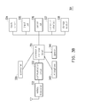
- FIG. 3B illustrates the hardware of a mobile electronic device in terms of functional block diagrams in accordance with one of the exemplary embodiments of the present disclosure.
- FIG. 3C illustrates the hardware of an in-vehicle electronic system in terms of functional block diagrams in accordance with one of the exemplary embodiments of the present disclosure.
- FIG. 4A illustrates a method of controlling interaction through profile settings between an in-vehicle electronic system and a mobile electronic device from the perspective of the in-vehicle electronic system in accordance with one of the exemplary embodiments of the present disclosure.
- FIG. 4B illustrates a method of controlling interaction through profile settings between an in-vehicle electronic system and a mobile electronic device from the perspective of the mobile electronic device in accordance with one of the exemplary embodiments of the present disclosure.
- FIG. 5A illustrates another embodiment of controlling interaction between an in-vehicle electronic system and a mobile electronic device from the perspective of the in-vehicle electronic system in accordance with one of the exemplary embodiments of the present disclosure.
- FIG. 5B illustrates another embodiment of controlling interaction between an in-vehicle electronic system and a mobile electronic device from the perspective of the mobile electronic device in accordance with one of the exemplary embodiments of the present disclosure.
- FIG. 2 illustrates an overall proposed system of multiple in-vehicle electronic systems inside a motor vehicle in accordance with one of the exemplary embodiments of the present disclosure.
- in-vehicle electronic systems 201 being accessible to a front row driver and situated next to a steering wheel
- the present disclosure is not limited to the exact arrangement of FIG.
- each of the in-vehicle electronic systems 201 ⁇ 204 could be plugged into each of the in-vehicle electronic systems 201 ⁇ 204 and thus host various applications.
- a portable electronic device (not shown) could be plugged into each of the in-vehicle electronic systems 201 ⁇ 204 and thus host various applications.
- Each of the in-vehicle electronic systems 201 ⁇ 204 could be internally integrated into the mechanical structure and / or electrical system of the motor vehicle, but the in-vehicle electronic systems 202 ⁇ 204 could actually be externally coupled to the mechanical structure of the motor vehicle and may or may not directly connected electrically to the motor vehicle.
- each of the electronic systems 201 ⁇ 204 could be independent and separately user configurable.
- FIG. 3A illustrates a mobile electronic device interacting with an in-vehicle electronic system inside a motor vehicle in accordance with one of the exemplary embodiments of the present disclosure.
- the in-vehicle electronic system 302 When the mobile electronic device 301 is connected to the in-vehicle electronic system 302, the in-vehicle electronic system 302 would be switched to a remote viewing mode and would interact with the mobile electronic device 301 through an electrical hardware interface which may include a display interface 321, a control interface 322, and an audio / voice interface 323.
- the mobile electronic device 301 may transfer displayed content of its touch screen 311 to the touch screen 312 of in-vehicle electronic system 302 such that the screen content of the in-vehicle electronic system 302 could be a near mirror image or an identical image of the screen content of the mobile electronic device 301.
- the in-vehicle electronic system 302 in the remote viewing mode could be thought of as a temporary monitor, or a temporary projector, or a remote touch screen of the mobile electronic device 301.
- the resulting control signal from the user operating on the touch screen 312 is transferred to the mobile electronic device 301 through the control interface 322 as though the touch screen 311 of the mobile electronic device 301 has been operated on such as the user may access functions and features of the mobile electronic device 301.
- control interface 112 of an in-vehicle electronic system 101 or 302 may contain a button which may temporarily switch the screen content of the touch screen 312 to a default home screen of the in-vehicle electronic system 302 so that when a user operates on the touch screen 312 of the in-vehicle electronic system 302, the user would be able to temporarily access the functions of the in-vehicle electronic system 302 instead of the mobile electronic device 301.
- the operating system of the in-vehicle electronic system 302 would disable the remote viewing mode and resume the normal operation of the in-vehicle electronic system 302.
- the aforementioned electrical hardware interface would further include a two way audio / voice interface 323 which could transfer audio or voice signal between the mobile electronic device 301 and the in-vehicle electronic system 302 both ways. For instance, a user may activate a music player from the mobile electronic device 301, and the music would be heard from the speaker of the in-vehicle electronic system 302. Likewise, a user may have a phone conversation through a microphone of the in-vehicle electronic system 302, and the audio voice would be transferred through the audio / voice interface 323 to the mobile electronic device 301 in order to be transmitted from the antenna of the mobile electronic device 301.
- FIG. 3B illustrates the hardware of a mobile electronic device in terms of functional block diagrams in accordance with one of the exemplary embodiments of the present disclosure.
- An exemplary mobile electronic device 301 could be a smart phone, a mobile phone, a person digital assistant (PDA), a tablet, a notebook computer, and so forth.
- PDA person digital assistant
- An exemplary mobile electronic device 301 would include a processor and controller circuit 331.
- the processor and controller circuit 331 would be electrically coupled to at least but not limited to a wireless transceiver 332, communication circuit 333, a touch screen 334, an input unit 335, a sensor unit 336, a connection interface 337, a storage medium 338, accessories 339, and an audio controller interface which may include a speaker 341 and a microphone 340.
- the processor and controller circuit 331 may include a micro-controller, a North Bridge, a South Bridge, a field programmable array (FPGA), a programmable logic device (PLD), an application specific integrated circuit (ASIC), or other similar device, or a combination therefore.
- FPGA field programmable array
- PLD programmable logic device
- ASIC application specific integrated circuit
- the processor and controller circuit 331 may also include a central processing unit (CPU) or a programmable general purpose or special purpose microprocessor, a digital signal processor (DSP), a graphics processing unit (GPU), an application specific integrated circuit (ASIC), a programmable logic device (PLD), or other similar device or a combination thereof, which is used for processing all tasks of the exemplary mobile electronic device 301.
- CPU central processing unit
- DSP digital signal processor
- GPU graphics processing unit
- ASIC application specific integrated circuit
- PLD programmable logic device
- the communication circuit 333 could be components which support signal transmissions of a global system for mobile communication (GSM), a personal handy-phone system (PHS), a code division multiple access (CDMA) system, a wireless fidelity (Wi-Fi) system or a worldwide interoperability for microwave access (WiMAX).
- GSM global system for mobile communication
- PHS personal handy-phone system
- CDMA code division multiple access
- Wi-Fi wireless fidelity
- WiMAX worldwide interoperability for microwave access
- the communication circuit 333 may be coupled to a wireless transceiver unit 332 to provide wireless access for the mobile electronic device 301.
- the wireless transceiver unit 332 may include but not limited to a transmitter circuit, a receiver circuit, an analog-to-digital (A/D) converter, a digital-to-analog (D/A) converter, a low noise amplifier (LNA), mixers, filters, matching networks, transmission lines, a power amplifier (PA), one or more antenna units, and a local storage medium.
- the transmitter and the receiver transmit downlink signals and receive uplink signals wirelessly.
- the receiver may include functional elements to perform operations such as low noise amplifying, impedance matching, frequency mixing, down frequency conversion, filtering, amplifying, and so forth.
- the transmitter may include function elements to perform operations such as amplifying, impedance matching, frequency mixing, up frequency conversion, filtering, power amplifying, and so forth.
- the analog-to-digital (A/D) or the digital-to-analog (D/A) converter is configured to convert from an analog signal format to a digital signal format during uplink signal processing and from a digital signal format to an analog signal format during downlink signal processing.
- the touch screen 334 may contain a display such as a liquid crystal display (LCD), a light-emitting diode (LED) display, a field emission display (FED) or other types of display.
- the input unit 335 could be, for example, an input device such as a mouse, a keyboard, a joystick, a wheel, and so forth and would receive an input operation from a user.
- the input unit 335 may also include a resistive, a capacitive or other types of touch sensing device which would be integrated as a part of the touch screen 334.
- the sensor unit 336 may contain various sensors such as a G-sensor, a gyroscope, a motion sensor, a proximity sensor, and so forth.
- connection interface 337 could be, for example, a cable interface such as a universal serial bus (USB) or a wireless interface such as Bluetooth.
- the connection interface 337 could be a serial interface such as RS232 interface or could be a parallel interface such as USB or Firewire.
- the storage medium 338 could volatile or permanent memories which would store buffered or permanent data such as compiled programming codes used to execute functions of the exemplary mobile electronic device 301.
- FIG. 3C illustrates the hardware of an in-vehicle electronic system in terms of functional block diagrams in accordance with one of the exemplary embodiments of the present disclosure.
- An exemplary in-vehicle electronic system 302 may include at least but not limited to a processor & control circuit 351, a touch screen 354, an input unit 355, a sensor unit 356, a connection interface 357, a storage medium 358, a microphone 360, and a speaker 361. Functionally these elements would be similar to a mobile electronic device 301 and hence the same descriptions will not be repeated.
- An in-vehicle electronic system 302 may further include a wireless communication circuit 352 so that the interaction between the mobile electronic device 301 and the in-vehicle electronic system 302 could occur over a variety of transports.
- the mobile electronic device 301 may either plug into the in-vehicle electronic system 302 through their connection interfaces 337 357 such as USB, or they may inter-connect wirelessly through a free spectrum such as using the Bluetooth or Wifi technology.
- the in-vehicle electronic system 302 may also wireless connect to an external host 370 which is not native to the motor vehicle.
- connection interfaces 337 357 or between the wireless circuits 332 352 could be based on a version of the MirrorLink communication protocol.
- present disclosure is not limited to MirrorLink as a person of ordinary skill in the art may substitute other protocols to implement various concepts of the present disclosure.
- the method of the present disclosure is premised upon the concept that certain functions of a mobile electronic device would be restricted during certain circumstances; however, the level of restriction would not apply universally to all in-vehicle electronic systems but would be different according to the role of each in-vehicle electronic system.
- the driver role or the driver in-vehicle electronic system would be imposed with restrictions while in-vehicle electronic system elsewhere would be unrestricted or less restricted.
- the role of the in-vehicle electronic system would determine the level of restriction on the accessible functions of a mobile electronic device.
- the restriction could be implemented through a profile settings which could be a default profile setting or a user customized profile setting.
- a customized profile setting is not available as the profile setting cannot be user defined in order to minimize tempering of the originally intended safety restriction.
- different roles i.e. driver, front seat passenger, rear seat passengers
- the driver would have different profile settings, and in general the driver would be the most restrictive and rear seat passengers would be the least restrictive.
- profile setting controls the interaction between the mobile electronic device and the in-vehicle electronic system merely by explicitly stating the role of the in-vehicle electronic device in the profile setting so that the profile setting is very easy to configure. After the mobile electronic device obtains the role of the in-vehicle electronic device through the profile setting, the mobile electronic device would then automatically apply restrictions by default according to the role of the in-vehicle electronic device.
- the user customized profile setting is available and could be configured based on discrete levels such that different functions could be enabled or disable altogether for each level as higher levels would have more functions restricted than lower level.
- the profile setting could also be configured by choosing a discrete package or by selecting functions on a function by function basis. However, regardless of how the profile setting is customized, the driver in-vehicle electronic system would be more restricted than non-driver in-vehicle electronic systems.
- the regulation related information could be downloaded automatically through a wireless communication circuit 332 333 352 so that the profile setting could be customized based on the location of the motor vehicle. For instance, when a vehicle travels to a US state where text messaging is banned, such regulation related information would be known by an external server. The external server could disseminate such information from a service website. When the in-vehicle electronic device 302 or the mobile electronic device 301 accesses the service website, such regulation related information could automatically downloaded from the external server in order to be integrated into the default profile setting so that text messaging would be automatically disabled in the driver in-vehicle electronic system when a driver is driving a motor vehicle.
- FIG. 4A illustrates a method of controlling interaction through profile settings between an in-vehicle electronic system and a mobile electronic device from the perspective of the in-vehicle electronic system in accordance with one of the exemplary embodiments of the present disclosure
- FIG. 4A operates as follows.
- a user may optionally configure or customize the profile settings of an in-vehicle electronic system, or otherwise the default profile setting would be adopted by default.
- the profile settings could be configured through a system menu of the in-vehicle electronic system by changing the restriction level, the package setting or by checking and un-checking boxes next to each functional descriptions.
- the present disclosure does not limit the manners of configuring the profile settings. For exemplary purpose, it is assumed that the default setting would be used.
- a connection would be established so that the in-vehicle electronic system would be actively connected to a mobile electronic device.
- An active connection includes the assumption that the mobile electronic device is turned on and would be in the position to engage the in-vehicle electronic system.
- the connection could be through connection interfaces (e.g. 337, 357, such as USB interface) or through direct wireless connection over free spectrums such as Wifi or Bluetooth through communication circuits (e.g. 332, 333, 352).
- connection interfaces e.g. 337, 357, such as USB interface
- Wifi or Bluetooth through communication circuits
- step S404 after the profile setting has been transferred to the mobile device, the in-vehicle electronic system would interact with the mobile electronic device based on the aforementioned principle as described under FIG. 3A , namely, the touch screen 312 of the in-vehicle electronic system 302 would function like a remote touch screen of the touch screen 311 of the mobile electronic device 301, and the mobile electronic device 301 would host applications to provide various functions and features.
- the mobile electronic device may restrict the functions and features provided for the in-vehicle electronic system.
- step S405 whenever a user alters the profile setting in an in-vehicle electronic system, the profile setting would be transfer over to the mobile electronic device automatically as long as the in-vehicle electronic system is actively connected to the mobile electronic device, and the mobile electronic device would immediately be operating according to the updated profile setting.
- FIG. 4B illustrates a method of controlling interaction through profile settings between an in-vehicle electronic system and a mobile electronic device from the perspective of the mobile electronic device in accordance with one of the exemplary embodiments of the present disclosure.
- the mobile electronic device has established an active electrical connection with an in-vehicle electronic system.
- the connection between the mobile electronic device and the in-vehicle electronic system could be a cable connection through a serial interface or could be a direct wireless connection. In one exemplary embodiment, the connection could be based on a MirrorLink protocol or any other protocol.
- the mobile electronic device would receive a profile setting from the in-vehicle electronic system.
- the profile setting could be a customized profile setting or a default profile setting.
- the mobile electronic device would obtain from the default profile setting the role of the in-vehicle electronic system as the role would be explicitly indicated in the default profile setting.
- the role of in-vehicle could be deduced from the default profile setting without being made explicit such as when the in-vehicle electronic system is built in and permanently fixed to the motor vehicle.
- the mobile electronic device would interact with the in-vehicle electronic system based on the role as indicated in the default profile setting.
- the mobile electronic device may restrict the functions or certain features hosted by the mobile electronic device according to the role defined in profile setting or according to customized profile setting.
- the purpose of the restriction is to minimize distractions by eliminating non-essential or distracting features provided by the mobile electronic device.
- the mobile electronic device could restrict the access to entertainment features such as music or movies by choosing not to activate them or by choosing not to transmit data over the connection interface 321 322 323.
- the mobile electronic device would also restrict the usage of text messages or instant messages by blocking them or by not transmitting them through the control interface.
- the mobile electronic device would by default allow music and notifications of incoming phone calls, since music and picking up an incoming phone call would be considered less distracting.
- incoming calls would not be allowed for the role of driver in-vehicle electronic system as long as the motor vehicle is moving, if the vehicle electronic system has determined that the current location has banned cell phone conversations while driving.
- the mobile electronic device would not restrict access by choosing not to access certain programs or by blocking certain functions and notifications. But instead, the in-vehicle electronic system would restrict the transmission and reception of data with the mobile electronic device if the role of in-vehicle electronic system is the driver in-vehicle electronic system and the in-vehicle electronic system would not restrict the transmission and reception of data with the in-vehicle electronic system if the in-vehicle electronic system were the passenger in-vehicle electronic system.
- the driver in-vehicle electronic system may restrict access by restricting the data transmission in the audio / voice interface 323 and the data transmission in the display interface 321.
- the In-vehicle electronic system may utilizes its own processor & controller circuit 351 to block the transmission of phone calls, music, and movies from the mobile electronic device as well as filtering out text messages except for incoming phone calls.
- the operation for the driver role could be restricted in several ways.
- the driver in-vehicle electronic system could be restricted by locking the touch screen 312 of the in-vehicle electronic system or by deactivating input to the touch screen in-vehicle electronic system or by interrupting the interface 321 322 323 between the touch screen 312 of the driver in-vehicle electronic system and the mobile electronic device.
- the restriction of the driver role could also include restriction of the hardware interface of the in-vehicle electronic system such as buttons, knobs, dials.
- the mobile electronic device attaches to a non-driver in-vehicle electronic system instead, the user is free to operate the touch screen and bottoms of the non-driver in-vehicle electronic system. Otherwise, if the mobile electronic device attaches to a non-driver in-vehicle electronic system instead, the user is free to operate the touch screen of the non-driver in-vehicle electronic system.
- the non-driver role may further includes a non-caller role such that a user may access entertainment features of the in-vehicle electronic system but would not be allowed to utilize communication related functions.
- a non-caller role such that a user may access entertainment features of the in-vehicle electronic system but would not be allowed to utilize communication related functions.
- the profile setting of the in-vehicle electronic system could configure a restricted passenger role which restrict the passenger in-vehicle electronic system but in a different way relative to the driver in-vehicle electronic system.
- the restricted passenger role of the in-vehicle electronic system could not access communication functions such as phone calls, emails, messages but could otherwise have full access to all other functions.
- the restriction of the transmission and reception of data between the mobile electronic device and the in-vehicle electronic system could be either further restricted or relaxed based on a dynamic consideration of the motor vehicle. For instance, when a motor vehicle is parked or is not parked but in a complete stop, all functions and features provided by a mobile electronic device would be unrestricted for all roles of the in-vehicle electronic systems. When a motor vehicle is parked for example, the in-vehicle electronic system may either transmit an independent signal to the mobile electronic device signaling that all functions and features could be allowed or the in-vehicle electronic system may transmit to the mobile electronic device an updated profile setting indicating that the motor vehicle has been parked.
- the dynamic consideration could be related to road conditions as experienced by a mobile electronic device such that a restriction would be relaxed if the mobile electronic device experiences stable road conditions.
- a mobile electronic device is equipped with various sensors such as a G-sensor or a gyro-sensor, the mobile electronic device would measure the acceleration and the angular momentum of the mobile electronic device. For instance, when an in-vehicle electronic system has informed a mobile electronic device that it is below a certain threshold and at the same time a driver does not make a sharp turn or accelerate beyond an acceleration threshold or decelerate the vehicle beyond a deceleration threshold such as by hitting the breaks over a predetermined period of time, all functions and features would be unrestricted by the mobile electronic device.
- the dynamic consideration could be related to sensor readings obtained by an in-vehicle electronic device such that restrictions would be further restricted if the sensor readings of the motor vehicle exceed a certain limit. For instance, if the speedometer has exceeded a certain threshold or if the vehicle has accelerated or decelerated beyond a certain threshold, the in-vehicle electronic system could either inform such event to the mobile electronic device in order for functions and features to be further restricted or the in-vehicle electronic system could disable certain functions such as by not allowing incoming calls, or by disabling music to be played for the driver in-vehicle electronic system.
- the dynamic consideration could be related to driver availability as detected by an in-vehicle electronic device such that restrictions would be further restricted if the driver has been determined to be busy operating the motor vehicle. For instance, if the vehicle has accelerated and / or decelerated a number of times over a predetermined period, the driver could be determined to be busy operating the motor vehicle since this would mean that the driver is frequently hitting the gas pedal or the breaks.
- the in-vehicle electronic system could either inform such event to the mobile electronic device in order for functions and features to be further restricted, or the in-vehicle electronic system could disable certain functions such as by not allowing incoming calls or by disabling music to be played.
- the dynamic consideration could be related to environmental conditions obtained by an in-vehicle electronic device such that restrictions would be further restricted if the environmental condition has been determined to unfavorable. For instance, if anti-lock breaks have been triggered to indicate snowy condition, the in-vehicle electronic system could either inform such event to the mobile electronic device in order for functions and features to be further restricted, or the in-vehicle electronic system could disable certain functions such as by not allowing incoming calls or by disabling music to be played.
- the dynamic consideration could be related to traffic condition obtained by an in-vehicle electronic device such that restrictions would be further restricted if the traffic condition has been determined to unfavorable through a connection with a wireless network. For instance, if the in-vehicle electronic system has logged into a server to obtain traffic information which has then be determined to be below a certain predetermined rating, the functions and features of the mobile electronic device would be further limited.
- the dynamic consideration could be related to environmental conditions obtained by an in-vehicle electronic device such that restrictions would be further restricted if certain features of the motor vehicle has been turned on. For instance, if the night visual assistance program of the in-vehicle electronic system has been turn on, or if the headlight of the motor vehicle is determined to be in the high beam mode, functions and features of the mobile electronic device would be further restricted by either having the in-vehicle electronic system transmitting a signal restricting certain feature(s) such as incoming calls or music or by having the in-vehicle electronic system disabling or block such features.
- FIG. 5A illustrates another embodiment of controlling interaction between an in-vehicle electronic system and a mobile electronic device from the perspective of the in-vehicle electronic system in accordance with one of the exemplary embodiments of the present disclosure.
- a user may optionally configure or customize the profile settings of an in-vehicle electronic system, or otherwise the user adopt the default profile setting.
- the profile settings could be indicating that each function provided by a mobile electronic device should be turned on or off individually, or the profile setting could indicate the role of the in-vehicle electronic system.
- step S502 a connection would be established between the in-vehicle electronic system and the mobile electronic device so that the in-vehicle electronic system would be actively connected to a mobile electronic device.
- connection could be through a connection interfaces (e.g. 337, 357, such as USB interface) or through direct wireless connection over free spectrums such as Wifi or Bluetooth through communication circuits (e.g. 332, 333, 352).
- connection interfaces e.g. 337, 357, such as USB interface
- direct wireless connection over free spectrums such as Wifi or Bluetooth through communication circuits (e.g. 332, 333, 352).
- Wifi or Bluetooth through communication circuits (e.g. 332, 333, 352).
- step S503 when the in-vehicle electronic system is connected to the mobile electronic device, the in-vehicle electronic system would in response transfer the profile setting to the mobile electronic device. Assuming that a default profile setting is used, the profile setting would explicitly indicate the role of the in-vehicle electronic system by default.
- step S504 after the profile setting has been transferred to the mobile device, the in-vehicle electronic system would apply various dynamic considerations in order to determine whether to relax or further restrict the restriction currently imposed on the in-vehicle electronic system as a driver in-vehicle electronic system would be restricted while a non-driver in-vehicle electronic system would access all functions and features of a mobile electronic device in an unrestricted manner.
- the various dynamic consideration could be any one or any combination of the aforementioned dynamic considerations and therefore a complete description will not be repeated.
- the in-vehicle electronic system would interact with the mobile electronic device based on the profile settings as well as dynamic considerations.
- step S506 whenever a user alters the profile setting in an in-vehicle electronic system, the profile setting would be transferred over to the mobile electronic device automatically as long as the in-vehicle electronic system is actively connected to the mobile electronic device, and the mobile electronic device would immediately be operating according to the updated profile setting.
- FIG. 5B illustrates another embodiment of controlling interaction between an in-vehicle electronic system and a mobile electronic device from the perspective of the mobile electronic device in accordance with one of the exemplary embodiments of the present disclosure.
- the mobile electronic device would establish an active electrical connection with an in-vehicle electronic system.
- the connection between the mobile electronic device and the in-vehicle electronic system could be a cable connection through a serial interface or could be a direct wireless connection. In one exemplary embodiment, the connection could be based on a MirrorLink protocol or any other protocol.
- the mobile electronic device would receive a profile setting from the in-vehicle electronic system.
- the profile setting could be a customized profile setting or a default profile setting.
- the mobile electronic device would extract from the default profile setting the role of the in-vehicle electronic system as the role would be explicitly indicated in the default profile setting.
- the mobile electronic device would determine whether to relax or to further restrict the functions and features provided to the in-vehicle electronic system in addition to the level of restriction as indicated by the profile setting.
- the dynamic consideration could include signals received from the in-vehicle electronic system or calculations performed from readings of various sensors which are native to the mobile electronic device. The dynamic consideration could any one or any combination of the aforementioned dynamic considerations and hence a complete description will not be repeated.
- the mobile electronic device would interact with the in-vehicle electronic system based on (the role as indicated by) the default profile setting as well as the dynamic considerations.
- the mobile electronic device would determine the functions and features provided to the in-vehicle electronic device based on the role as defined in the profile setting. If the profile setting has indicated that the in-vehicle electronic system has a non-driver role, then mobile electronic device may apply full access to the user of the in-vehicle electronic system. If the profile setting has indicated that the in-vehicle electronic system has a driver role, then by default the functions and features may only include music and incoming calls. The mobile electronic device may then determine whether to relax or to further restrict the functions and features based on dynamic considerations.
- the present disclosure extend the functions of an in-vehicle electronic system by incorporating various functions of a mobile electronic device into an in-vehicle electronic system not just for a driver of a motor vehicle but also for all passengers as each passenger could plug in one's mobile electronic device into a separate in-vehicle electronic system.
- the disclosure minimizes distractions caused by potentially distracting applications by dividing all in-vehicle electronic systems into separate roles. While functions provided for the driver role may be restricted, functions provided for non-driver role could be unrestricted or less restricted. Dynamic considerations could be applied to further relax or restrict the restriction imposed on the driver role.
Abstract
Description
- The embodiment of the present disclosure generally relates to a method of controlling interaction between a mobile electronic device and a in-vehicle electronic system, a mobile electronic device using the same method, and a in-vehicle electronic system unit using the same method.
- Presently, an average automobile could be equipped with more electronic features than a number of buttons and rotary dials, and consequently a collective interface equipped with a single touch screen and few buttons has been utilized in order to adequately account for all the control needs of a motor vehicle. The collective interface could generally be referred to as an "in-vehicle electronic system" but could also be identified by other labels such as an infotainment system, an in-car entertainment system, or a head unit. These features could range from basic automotive features such as the climate control, radio station tuning, music player control, to more non-basic features such as telephone functions, text messaging, internet surfing, GPS navigational system, satellite radio, rear view camera activation, night vision assistance, gaming systems, television services, and so forth. The in-vehicle electronic system may in fact be used to control and display almost everything on the vehicle including even features which are traditionally operated by buttons or switches external to the in-vehicle electronic system such as controls for seat adjustments or sun roofs.
- However, at this point in time, the processing hardware of an average smart phone would out-perform most in-vehicle electronic systems as a smart phone would possess more computing powers. A smart phone could also host a higher quantity of non-basic features and applications than an in-vehicle electronic system and is usually equipped with 3G which could be utilized to download various applications. Instead of purchasing a vehicle with all the functions and features which would have been readily available in one's a smart phone, a technology has recently been developed to enable a consumer to plug one's smart phone into one's in-vehicle electronic system in order to extend its functionality by harnessing the functions and features which already exists in the smart phone.
-
FIG. 1 illustrates a mobileelectronic device 102 interacting with an in-vehicleelectronic system 101. The in-vehicleelectronic system 101 would normally be situated in the upper part of the center of the dashboard in the front row of a vehicle and right next to asteering wheel 103 and in between the front side driver'sseat 104 and the front side passenger'sseat 105. The in-vehicleelectronic system 101 would include adisplay panel 111 integrated in the upper part of the center of the dashboard. The display panel would typically be a liquid crystal display (LCD) and would span between 6 to 12 inches in width, and thedisplay panel 111 could be coupled with capacitive input sensor to form a touch screen. Through a hierarchical menu displayed on thedisplay panel 111, soft buttons, knobs, and dials could be used to replace mechanical switches. However, below thedisplay panel 111, there may still be acontrol interface 112 to provide controls such that a user may turn off thedisplay panel 111 and still control functions and features within a vehicle or to operate vehicular control functions when thedisplay panel 111 is used as a proxy viewing device by an external host such as when thedisplay panel 111 is used to interact with a mobileelectronic device 102. Thecontrol interface 112 which provides interface functions to a user would typically include hardware inputs such as buttons, switches, knobs, and dials. - When a mobile
electronic device 102 is plugged into the in-vehicleelectronic system 101, the operating system of the in-vehicleelectronic system 101 would usually switch the in-vehicleelectronic system 101 to a remote viewing mode or an alternative operating mode which would essentially in some way synchronize the control and the display between the mobileelectronic device 102 and the in-vehicleelectronic system 101. When the mobile electronic 102 device is unplugged from the in-vehicleelectronic system 101, the operating system of the in-vehicleelectronic system 101 would resume its normal operation. - When an in-vehicle
electronic system 101 interacts with a mobileelectronic device 102, the interaction may proceed according to a predefined protocol. The protocol could be a customized protocol which is unique for each manufacturer, or otherwise the protocol could be a standardized protocol which could allow different brands of smart phones to be plugged into in-vehicle electronic systems produced by different manufacturers. One standardized protocol could be for example the MirrorLink standard which has been established by the automotive industry teaming up with consumer electronics to form the Car Connectivity Consortium on March, 2011. - Besides the potential difficulties of forming standards ahead, the integration between a mobile electronic device and an in-vehicle electronic system could pose another challenge which is related to the issue of driver distraction. With various entertaining applications accessible to a driver through one's mobile electronic device, the driver could be operating a motor vehicle with divided attention or even taking one's eyes off the road. According to more recent studies done on driving safety, it has been discovered that when a driver looks at the screen of the in-vehicle electronic system rather than the road, the driver is more prone to traffic accidents according to an exponentially increasing probability.
- Moreover, many countries in the world have already passed laws prohibiting a driver from speaking on a phone or using text messages while driving. In the United States, many states and territories have banned the use of mobile phones while driving, and even more states have banned text messaging for drivers. Meanwhile, debates ensue as for how to regulate and limit the contents of potentially distracting applications accessible to one's in-vehicle electronic system. Therefore, when a driver elects to use one's mobile electronic device in conjunction with one's in-vehicle electronic system, additional safety measures could be adopted in order to curtail various distractions which may divide one's driving attention, but while certain features could still be made accessible so that one may take advantage of some functions and features of one's mobile electronic device without getting sidetracked by the various distractions when driving.
- Accordingly, it is an object of the present disclosure to propose a method of controlling interaction between a mobile electronic device and a in-vehicle electronic system, a computer program product and a mobile electronic device using the same method, and a in-vehicle electronic system unit using the same method. The objects are achieved by the subject matter of independent claims. Other embodiments are characterised by dependent claims.
- In one of the exemplary embodiments, the proposed method is a method of controlling interaction between a mobile electronic device and an in-vehicular electronic system from the perspective of the mobile electronic device, and the method includes the steps of establishing a connection with the in-vehicle electronic system. After the connection has been established, the in-vehicle electronic system would transmit a profile setting to the mobile electronic device through the established connection. The mobile electronic device would then control the transmission and reception of data with the in-vehicle electronic system based on the profile setting, wherein the profile setting would vary based on the role of the in-vehicle electronic system.
- In one of the exemplary embodiments, the role of the in-vehicle electronic system may include a driver in-vehicle electronic system and a passenger in-vehicle electronic system. In one of the exemplary embodiment, the role of the passenger in-vehicle electronic system may further be specified as a front seat passenger in-vehicle electronic system or a back seat passenger in-vehicle electronic system.
- In one of the exemplary embodiments, the profile setting between the role of the driver in-vehicle electronic system and the role of the passenger in-vehicle electronic system would be the same. In this case, the interaction between the mobile electronic device and the in-vehicle electronic system would be the same regardless whether the in-vehicle electronic system is the driver in-vehicle electronic system or the passenger in-vehicle electronic system.
- In one of the exemplary embodiments, the profile setting between the role of the driver in-vehicle electronic system and the role of the passenger in-vehicle electronic system would be different. In this case, the interaction between the mobile electronic device and the in-vehicle electronic system would be the different based on whether the in-vehicle electronic system is the driver in-vehicle electronic system or the passenger in-vehicle electronic system.
- In one of the exemplary embodiments, the mobile electronic device restrict the transmission and reception of data with the in-vehicle electronic system if the role of in-vehicle electronic system is the driver in-vehicle electronic system and the mobile electronic device would not restrict the transmission and reception of data with the in-vehicle electronic system if the in-vehicle electronic system were the passenger in-vehicle electronic system.
- In one of the exemplary embodiments, the restriction of the transmission and reception of data is such that the transmission and reception of data is for incoming calls and / or music only.
- In one of the exemplary embodiments, the restriction of the transmission and reception of data is such that the transmission and reception of data would be unrestricted for all roles under circumstances such as when the vehicle is parked or in a complete stop.
- In one of the exemplary embodiments, the connection between the mobile electronic device and the in-vehicle electronic system could be a cable connection through a serial interface or could be a direct wireless connection.
- In one of the exemplary embodiments, the proposed method is a method of controlling interaction between a mobile electronic device and an in-vehicular electronic system from the perspective of the in-vehicular electronic system, and the method includes the steps of establishing a connection with the mobile electronic device. After the connection has been established, the in-vehicle electronic system would transmit a profile setting to the mobile electronic device through the established connection. The in-vehicle electronic system would then transmit and receive data with the mobile electronic device based on the profile setting, wherein the profile setting would vary based on the role of the in-vehicle electronic system.
- In one of the exemplary embodiments, the role of the in-vehicle electronic system may include a driver in-vehicle electronic system and a passenger in-vehicle electronic system.
- In one of the exemplary embodiments, the transmission and reception of data with the mobile electronic device would be restricted by the mobile electronic device if the role of in-vehicle electronic system is the driver in-vehicle electronic system and the transmission and reception of data with the mobile electronic device would not be restricted if the in-vehicle electronic system were the passenger in-vehicle electronic system.
- In one of the exemplary embodiments, the in-vehicle electronic system would restrict the transmission and reception of data with the mobile electronic device if the role of in-vehicle electronic system is the driver in-vehicle electronic system and the mobile electronic device would not restrict the transmission and reception of data with the in-vehicle electronic system if the in-vehicle electronic system were the passenger in-vehicle electronic system.
- In one of the exemplary embodiments, the restriction of the transmission and reception of data is such that the transmission and reception of data by the driver in-vehicle electronic system is for incoming calls only. The restricted data could be temporarily stored in a buffered memory and would eventually be allowed to be transmitted or received when the vehicle is parked or in a complete stop.
- In one of the exemplary embodiment, the present disclosure directs to a mobile electronic device which includes at least but not limited to a communication circuit and a processing circuit coupled to the communication circuit, wherein the processing circuit is configured for executing functions including establishing a connection with the in-vehicle electronic system through the communication circuit, receiving a profile setting of the in-vehicle electronic system through the connection after establishing the first connection with the in-vehicle electronic system, and controlling transmitting and receiving data through the communication circuit with the in-vehicle electronic system based on the profile setting of the in-vehicle electronic system, wherein the profile setting would vary based on the role of the in-vehicle electronic system. The mobile electronic device could also be configured to execute all the functions as disclosed in all of the embodiments.
- In one of the exemplary embodiment, the present disclosure directs to an in-vehicle electronic system which includes at least but not limited to a communication circuit and a processing circuit coupled to the communication circuit, wherein the processing circuit is configured for executing functions including establishing a connection with a mobile electronic device through the communication circuit, transferring a profile setting to the mobile electronic device through the connection after establishing the first connection to the mobile device, and transmitting and receiving data with the mobile electronic device through the communication circuit according to the profile setting, wherein the profile setting would vary based on the role of the in-vehicle electronic system. The in-vehicle electronic system could also be configured to execute all the functions as disclosed in all of the embodiments.
- In one of the exemplary embodiments, the interaction between a mobile electronic device and an in-vehicular electronic system could further be determined based on various dynamic factors in addition to the profile setting, wherein the profile setting would vary based on the role of the in-vehicle electronic system.
- In one of the exemplary embodiments, in response to the mobile electronic device attaching to the in-vehicle electronic system, the operation for the driver role could be restricted in several ways. The driver in-vehicle electronic system could be restricted by locking the touch screen of the in-vehicle electronic system or by deactivating input to the touch screen of the in-vehicle electronic system or by interrupting the interaction between the touch screen of the driver in-vehicle electronic system and the mobile electronic device. The restriction of the driver role could also include restriction of the hardware interface of the in-vehicle electronic system such as buttons, knobs, dials. Otherwise, if the mobile electronic device attaches to a non-driver in-vehicle electronic system instead, the user is free to operate the touch screen and bottoms of the non-driver in-vehicle electronic system.
- In one of the exemplary embodiments, the non-driver role may further includes a non-caller role such that a user may access entertainment features of the in-vehicle electronic system but would not be allowed to utilize communication related functions.
- In order to make the aforementioned features and advantages of the present disclosure comprehensible, preferred embodiments accompanied with figures are described in detail below. It is to be understood that both the foregoing general description and the following detailed description are exemplary, and are intended to provide further explanation of the disclosure as claimed.
- It should be understood, however, that this summary may not contain all of the aspect and embodiments of the present disclosure and is therefore not meant to be limiting or restrictive in any manner. Also the present disclosure would include improvements and modifications which are obvious to one skilled in the art.
- The accompanying drawings are included to provide a further understanding of the disclosure, and are incorporated in and constitute a part of this specification. The drawings illustrate embodiments of the disclosure and, together with the description, serve to explain the principles of the disclosure.
-
FIG. 1 illustrates a mobile electronic device interacting with an in-vehicle electronic system inside a motor vehicle. -
FIG. 2 illustrates multiple in-vehicle electronic system inside a motor vehicle in accordance with one of the exemplary embodiments of the present disclosure. -
FIG. 3A illustrates a mobile electronic device interacting with an in-vehicle electronic system inside a motor vehicle in accordance with one of the exemplary embodiments of the present disclosure. -
FIG. 3B illustrates the hardware of a mobile electronic device in terms of functional block diagrams in accordance with one of the exemplary embodiments of the present disclosure. -
FIG. 3C illustrates the hardware of an in-vehicle electronic system in terms of functional block diagrams in accordance with one of the exemplary embodiments of the present disclosure. -
FIG. 4A illustrates a method of controlling interaction through profile settings between an in-vehicle electronic system and a mobile electronic device from the perspective of the in-vehicle electronic system in accordance with one of the exemplary embodiments of the present disclosure. -
FIG. 4B illustrates a method of controlling interaction through profile settings between an in-vehicle electronic system and a mobile electronic device from the perspective of the mobile electronic device in accordance with one of the exemplary embodiments of the present disclosure. -
FIG. 5A illustrates another embodiment of controlling interaction between an in-vehicle electronic system and a mobile electronic device from the perspective of the in-vehicle electronic system in accordance with one of the exemplary embodiments of the present disclosure. -
FIG. 5B illustrates another embodiment of controlling interaction between an in-vehicle electronic system and a mobile electronic device from the perspective of the mobile electronic device in accordance with one of the exemplary embodiments of the present disclosure. - No element, act, or instruction used in the detailed description of disclosed embodiments of the present application should be construed as absolutely critical or essential to the present disclosure unless explicitly described as such. Also, as used herein, each of the indefinite articles "a" and "an" could include more than one item. If only one item is intended, the terms "a single" or similar languages would be used. Furthermore, the terms "any of" followed by a listing of a plurality of items and/or a plurality of categories of items, as used herein, are intended to include "any of", "any combination of", "any multiple of", and/or "any combination of multiples of the items and/or the categories of items, individually or in conjunction with other items and/or other categories of items. Further, as used herein, the term "set" is intended to include any number of items, including zero. Further, as used herein, the term "number" is intended to include any number, including zero.
-
FIG. 2 illustrates an overall proposed system of multiple in-vehicle electronic systems inside a motor vehicle in accordance with one of the exemplary embodiments of the present disclosure. In addition to an in-vehicleelectronic systems 201 being accessible to a front row driver and situated next to a steering wheel, there could also be an in-vehicleelectronic systems 202 in the front row passenger side, an in-vehicleelectronic systems 203 in the backseat of the driver's side, or an in-vehicleelectronic systems 204 in the backseat of the non-driver's side. However, the present disclosure is not limited to the exact arrangement ofFIG. 2 as a third in-vehicle electronic system could be added to the backseat in between 203 and 204 or additional in-vehicle electronic systems could also be added in the case that there are multiple rows of backseats. For each of the in-vehicleelectronic systems 201∼204, a portable electronic device (not shown) could be plugged into each of the in-vehicleelectronic systems 201∼204 and thus host various applications. Each of the in-vehicleelectronic systems 201∼204 could be internally integrated into the mechanical structure and / or electrical system of the motor vehicle, but the in-vehicleelectronic systems 202∼204 could actually be externally coupled to the mechanical structure of the motor vehicle and may or may not directly connected electrically to the motor vehicle. Also in accordance with one of the exemplary embodiments, each of theelectronic systems 201∼204 could be independent and separately user configurable. -
FIG. 3A illustrates a mobile electronic device interacting with an in-vehicle electronic system inside a motor vehicle in accordance with one of the exemplary embodiments of the present disclosure. When the mobileelectronic device 301 is connected to the in-vehicleelectronic system 302, the in-vehicleelectronic system 302 would be switched to a remote viewing mode and would interact with the mobileelectronic device 301 through an electrical hardware interface which may include adisplay interface 321, acontrol interface 322, and an audio /voice interface 323. - Through the
display interface 321, the mobileelectronic device 301 may transfer displayed content of itstouch screen 311 to thetouch screen 312 of in-vehicleelectronic system 302 such that the screen content of the in-vehicleelectronic system 302 could be a near mirror image or an identical image of the screen content of the mobileelectronic device 301. The in-vehicleelectronic system 302 in the remote viewing mode could be thought of as a temporary monitor, or a temporary projector, or a remote touch screen of the mobileelectronic device 301. When a user operates on thetouch screen 312 of the in-vehicleelectronic system 302, the resulting control signal from the user operating on thetouch screen 312 is transferred to the mobileelectronic device 301 through thecontrol interface 322 as though thetouch screen 311 of the mobileelectronic device 301 has been operated on such as the user may access functions and features of the mobileelectronic device 301. - According to one embodiment, the
control interface 112 of an in-vehicleelectronic system touch screen 312 to a default home screen of the in-vehicleelectronic system 302 so that when a user operates on thetouch screen 312 of the in-vehicleelectronic system 302, the user would be able to temporarily access the functions of the in-vehicleelectronic system 302 instead of the mobileelectronic device 301. When the user decides to unplug the mobileelectronic device 301 from the in-vehicleelectronic system 302, the operating system of the in-vehicleelectronic system 302 would disable the remote viewing mode and resume the normal operation of the in-vehicleelectronic system 302. - The aforementioned electrical hardware interface would further include a two way audio /
voice interface 323 which could transfer audio or voice signal between the mobileelectronic device 301 and the in-vehicleelectronic system 302 both ways. For instance, a user may activate a music player from the mobileelectronic device 301, and the music would be heard from the speaker of the in-vehicleelectronic system 302. Likewise, a user may have a phone conversation through a microphone of the in-vehicleelectronic system 302, and the audio voice would be transferred through the audio /voice interface 323 to the mobileelectronic device 301 in order to be transmitted from the antenna of the mobileelectronic device 301. -
FIG. 3B illustrates the hardware of a mobile electronic device in terms of functional block diagrams in accordance with one of the exemplary embodiments of the present disclosure. An exemplary mobileelectronic device 301 could be a smart phone, a mobile phone, a person digital assistant (PDA), a tablet, a notebook computer, and so forth. - An exemplary mobile
electronic device 301 would include a processor andcontroller circuit 331. The processor andcontroller circuit 331 would be electrically coupled to at least but not limited to awireless transceiver 332,communication circuit 333, atouch screen 334, aninput unit 335, asensor unit 336, aconnection interface 337, astorage medium 338,accessories 339, and an audio controller interface which may include aspeaker 341 and amicrophone 340. The processor andcontroller circuit 331 may include a micro-controller, a North Bridge, a South Bridge, a field programmable array (FPGA), a programmable logic device (PLD), an application specific integrated circuit (ASIC), or other similar device, or a combination therefore. The processor andcontroller circuit 331 may also include a central processing unit (CPU) or a programmable general purpose or special purpose microprocessor, a digital signal processor (DSP), a graphics processing unit (GPU), an application specific integrated circuit (ASIC), a programmable logic device (PLD), or other similar device or a combination thereof, which is used for processing all tasks of the exemplary mobileelectronic device 301. - The
communication circuit 333 could be components which support signal transmissions of a global system for mobile communication (GSM), a personal handy-phone system (PHS), a code division multiple access (CDMA) system, a wireless fidelity (Wi-Fi) system or a worldwide interoperability for microwave access (WiMAX). Thecommunication circuit 333 may be coupled to awireless transceiver unit 332 to provide wireless access for the mobileelectronic device 301. Thewireless transceiver unit 332 may include but not limited to a transmitter circuit, a receiver circuit, an analog-to-digital (A/D) converter, a digital-to-analog (D/A) converter, a low noise amplifier (LNA), mixers, filters, matching networks, transmission lines, a power amplifier (PA), one or more antenna units, and a local storage medium. The transmitter and the receiver transmit downlink signals and receive uplink signals wirelessly. The receiver may include functional elements to perform operations such as low noise amplifying, impedance matching, frequency mixing, down frequency conversion, filtering, amplifying, and so forth. The transmitter may include function elements to perform operations such as amplifying, impedance matching, frequency mixing, up frequency conversion, filtering, power amplifying, and so forth. The analog-to-digital (A/D) or the digital-to-analog (D/A) converter is configured to convert from an analog signal format to a digital signal format during uplink signal processing and from a digital signal format to an analog signal format during downlink signal processing. - The
touch screen 334 may contain a display such as a liquid crystal display (LCD), a light-emitting diode (LED) display, a field emission display (FED) or other types of display. Theinput unit 335 could be, for example, an input device such as a mouse, a keyboard, a joystick, a wheel, and so forth and would receive an input operation from a user. Theinput unit 335 may also include a resistive, a capacitive or other types of touch sensing device which would be integrated as a part of thetouch screen 334. - The
sensor unit 336 may contain various sensors such as a G-sensor, a gyroscope, a motion sensor, a proximity sensor, and so forth. - The
connection interface 337 could be, for example, a cable interface such as a universal serial bus (USB) or a wireless interface such as Bluetooth. Theconnection interface 337 could be a serial interface such as RS232 interface or could be a parallel interface such as USB or Firewire. - The
storage medium 338 could volatile or permanent memories which would store buffered or permanent data such as compiled programming codes used to execute functions of the exemplary mobileelectronic device 301. -
FIG. 3C illustrates the hardware of an in-vehicle electronic system in terms of functional block diagrams in accordance with one of the exemplary embodiments of the present disclosure. An exemplary in-vehicleelectronic system 302 may include at least but not limited to a processor &control circuit 351, atouch screen 354, aninput unit 355, asensor unit 356, aconnection interface 357, astorage medium 358, amicrophone 360, and aspeaker 361. Functionally these elements would be similar to a mobileelectronic device 301 and hence the same descriptions will not be repeated. - An in-vehicle
electronic system 302 may further include awireless communication circuit 352 so that the interaction between the mobileelectronic device 301 and the in-vehicleelectronic system 302 could occur over a variety of transports. The mobileelectronic device 301 may either plug into the in-vehicleelectronic system 302 through theirconnection interfaces 337 357 such as USB, or they may inter-connect wirelessly through a free spectrum such as using the Bluetooth or Wifi technology. Furthermore, the in-vehicleelectronic system 302 may also wireless connect to anexternal host 370 which is not native to the motor vehicle. - The communication protocol between the connection interfaces 337 357 or between the
wireless circuits 332 352 could be based on a version of the MirrorLink communication protocol. However, the present disclosure is not limited to MirrorLink as a person of ordinary skill in the art may substitute other protocols to implement various concepts of the present disclosure. - The method of the present disclosure is premised upon the concept that certain functions of a mobile electronic device would be restricted during certain circumstances; however, the level of restriction would not apply universally to all in-vehicle electronic systems but would be different according to the role of each in-vehicle electronic system. In one exemplary embodiment, the driver role or the driver in-vehicle electronic system would be imposed with restrictions while in-vehicle electronic system elsewhere would be unrestricted or less restricted. In other words, the role of the in-vehicle electronic system would determine the level of restriction on the accessible functions of a mobile electronic device. The restriction could be implemented through a profile settings which could be a default profile setting or a user customized profile setting.
- According to one exemplary embodiment, a customized profile setting is not available as the profile setting cannot be user defined in order to minimize tempering of the originally intended safety restriction. In this embodiment, different roles (i.e. driver, front seat passenger, rear seat passengers) would have different profile settings, and in general the driver would be the most restrictive and rear seat passengers would be the least restrictive.
- In one exemplary embodiment, profile setting controls the interaction between the mobile electronic device and the in-vehicle electronic system merely by explicitly stating the role of the in-vehicle electronic device in the profile setting so that the profile setting is very easy to configure. After the mobile electronic device obtains the role of the in-vehicle electronic device through the profile setting, the mobile electronic device would then automatically apply restrictions by default according to the role of the in-vehicle electronic device.
- According to another exemplary embodiment, the user customized profile setting is available and could be configured based on discrete levels such that different functions could be enabled or disable altogether for each level as higher levels would have more functions restricted than lower level. The profile setting could also be configured by choosing a discrete package or by selecting functions on a function by function basis. However, regardless of how the profile setting is customized, the driver in-vehicle electronic system would be more restricted than non-driver in-vehicle electronic systems.
- In one exemplary embodiment, the regulation related information could be downloaded automatically through a
wireless communication circuit 332 333 352 so that the profile setting could be customized based on the location of the motor vehicle. For instance, when a vehicle travels to a US state where text messaging is banned, such regulation related information would be known by an external server. The external server could disseminate such information from a service website. When the in-vehicleelectronic device 302 or the mobileelectronic device 301 accesses the service website, such regulation related information could automatically downloaded from the external server in order to be integrated into the default profile setting so that text messaging would be automatically disabled in the driver in-vehicle electronic system when a driver is driving a motor vehicle. -
FIG. 4A illustrates a method of controlling interaction through profile settings between an in-vehicle electronic system and a mobile electronic device from the perspective of the in-vehicle electronic system in accordance with one of the exemplary embodiments of the present disclosure, andFIG. 4A operates as follows. In optional step S401, a user may optionally configure or customize the profile settings of an in-vehicle electronic system, or otherwise the default profile setting would be adopted by default. The profile settings could be configured through a system menu of the in-vehicle electronic system by changing the restriction level, the package setting or by checking and un-checking boxes next to each functional descriptions. However, the present disclosure does not limit the manners of configuring the profile settings. For exemplary purpose, it is assumed that the default setting would be used. In step S402, a connection would be established so that the in-vehicle electronic system would be actively connected to a mobile electronic device. An active connection includes the assumption that the mobile electronic device is turned on and would be in the position to engage the in-vehicle electronic system. The connection could be through connection interfaces (e.g. 337, 357, such as USB interface) or through direct wireless connection over free spectrums such as Wifi or Bluetooth through communication circuits (e.g. 332, 333, 352). In step S403, when the in-vehicle electronic system is connected to the mobile electronic device, the in-vehicle electronic system in response would transfer the profile setting to the mobile electronic device. Assuming that a default profile setting is used, the profile setting would explicitly indicate the role of the in-vehicle electronic system. In step S404, after the profile setting has been transferred to the mobile device, the in-vehicle electronic system would interact with the mobile electronic device based on the aforementioned principle as described underFIG. 3A , namely, thetouch screen 312 of the in-vehicleelectronic system 302 would function like a remote touch screen of thetouch screen 311 of the mobileelectronic device 301, and the mobileelectronic device 301 would host applications to provide various functions and features. However, the mobile electronic device may restrict the functions and features provided for the in-vehicle electronic system. In optional step S405, whenever a user alters the profile setting in an in-vehicle electronic system, the profile setting would be transfer over to the mobile electronic device automatically as long as the in-vehicle electronic system is actively connected to the mobile electronic device, and the mobile electronic device would immediately be operating according to the updated profile setting. -
FIG. 4B illustrates a method of controlling interaction through profile settings between an in-vehicle electronic system and a mobile electronic device from the perspective of the mobile electronic device in accordance with one of the exemplary embodiments of the present disclosure. In step S451, the mobile electronic device has established an active electrical connection with an in-vehicle electronic system. The connection between the mobile electronic device and the in-vehicle electronic system could be a cable connection through a serial interface or could be a direct wireless connection. In one exemplary embodiment, the connection could be based on a MirrorLink protocol or any other protocol. In step S452, the mobile electronic device would receive a profile setting from the in-vehicle electronic system. The profile setting could be a customized profile setting or a default profile setting. For exemplary purpose, assuming that a default profile setting has been obtained, the mobile electronic device would obtain from the default profile setting the role of the in-vehicle electronic system as the role would be explicitly indicated in the default profile setting. In some cases, the role of in-vehicle could be deduced from the default profile setting without being made explicit such as when the in-vehicle electronic system is built in and permanently fixed to the motor vehicle. In step S453, the mobile electronic device would interact with the in-vehicle electronic system based on the role as indicated in the default profile setting. - More specifically, in step S453, after the mobile electronic device has received the profile setting, the mobile electronic device may restrict the functions or certain features hosted by the mobile electronic device according to the role defined in profile setting or according to customized profile setting. The purpose of the restriction is to minimize distractions by eliminating non-essential or distracting features provided by the mobile electronic device. For instance, the mobile electronic device could restrict the access to entertainment features such as music or movies by choosing not to activate them or by choosing not to transmit data over the
connection interface 321 322 323. The mobile electronic device would also restrict the usage of text messages or instant messages by blocking them or by not transmitting them through the control interface. The mobile electronic device would by default allow music and notifications of incoming phone calls, since music and picking up an incoming phone call would be considered less distracting. Placing an outgoing call would be restricted by default since it would be considered distracting for a driver to look up a phone number and to press buttons to make a call. However, if the role as defined in the profile setting has indicated that the in-vehicle electronic system is a non-driver role, then mobile electronic device may apply full access to the user of the in-vehicle electronic system. - In another exemplary embodiment, incoming calls would not be allowed for the role of driver in-vehicle electronic system as long as the motor vehicle is moving, if the vehicle electronic system has determined that the current location has banned cell phone conversations while driving.
- In another exemplary embodiment, the mobile electronic device would not restrict access by choosing not to access certain programs or by blocking certain functions and notifications. But instead, the in-vehicle electronic system would restrict the transmission and reception of data with the mobile electronic device if the role of in-vehicle electronic system is the driver in-vehicle electronic system and the in-vehicle electronic system would not restrict the transmission and reception of data with the in-vehicle electronic system if the in-vehicle electronic system were the passenger in-vehicle electronic system. The driver in-vehicle electronic system may restrict access by restricting the data transmission in the audio /
voice interface 323 and the data transmission in thedisplay interface 321. For instance, the In-vehicle electronic system may utilizes its own processor &controller circuit 351 to block the transmission of phone calls, music, and movies from the mobile electronic device as well as filtering out text messages except for incoming phone calls. - In one of the exemplary embodiments, in response to the mobile electronic device attaching to the in-vehicle electronic system, the operation for the driver role could be restricted in several ways. The driver in-vehicle electronic system could be restricted by locking the
touch screen 312 of the in-vehicle electronic system or by deactivating input to the touch screen in-vehicle electronic system or by interrupting theinterface 321 322 323 between thetouch screen 312 of the driver in-vehicle electronic system and the mobile electronic device. The restriction of the driver role could also include restriction of the hardware interface of the in-vehicle electronic system such as buttons, knobs, dials. Otherwise, if the mobile electronic device attaches to a non-driver in-vehicle electronic system instead, the user is free to operate the touch screen and bottoms of the non-driver in-vehicle electronic system. Otherwise, if the mobile electronic device attaches to a non-driver in-vehicle electronic system instead, the user is free to operate the touch screen of the non-driver in-vehicle electronic system. - In one of the exemplary embodiments, the non-driver role may further includes a non-caller role such that a user may access entertainment features of the in-vehicle electronic system but would not be allowed to utilize communication related functions. For example, if the in-vehicle electronic system were meant to be operated by children, the profile setting of the in-vehicle electronic system could configure a restricted passenger role which restrict the passenger in-vehicle electronic system but in a different way relative to the driver in-vehicle electronic system. In this case, the restricted passenger role of the in-vehicle electronic system could not access communication functions such as phone calls, emails, messages but could otherwise have full access to all other functions.
- In one of the exemplary embodiments, the restriction of the transmission and reception of data between the mobile electronic device and the in-vehicle electronic system could be either further restricted or relaxed based on a dynamic consideration of the motor vehicle. For instance, when a motor vehicle is parked or is not parked but in a complete stop, all functions and features provided by a mobile electronic device would be unrestricted for all roles of the in-vehicle electronic systems. When a motor vehicle is parked for example, the in-vehicle electronic system may either transmit an independent signal to the mobile electronic device signaling that all functions and features could be allowed or the in-vehicle electronic system may transmit to the mobile electronic device an updated profile setting indicating that the motor vehicle has been parked.
- In another exemplary embodiment, the dynamic consideration could be related to road conditions as experienced by a mobile electronic device such that a restriction would be relaxed if the mobile electronic device experiences stable road conditions. Since a mobile electronic device is equipped with various sensors such as a G-sensor or a gyro-sensor, the mobile electronic device would measure the acceleration and the angular momentum of the mobile electronic device. For instance, when an in-vehicle electronic system has informed a mobile electronic device that it is below a certain threshold and at the same time a driver does not make a sharp turn or accelerate beyond an acceleration threshold or decelerate the vehicle beyond a deceleration threshold such as by hitting the breaks over a predetermined period of time, all functions and features would be unrestricted by the mobile electronic device.
- In one exemplary embodiment, the dynamic consideration could be related to sensor readings obtained by an in-vehicle electronic device such that restrictions would be further restricted if the sensor readings of the motor vehicle exceed a certain limit. For instance, if the speedometer has exceeded a certain threshold or if the vehicle has accelerated or decelerated beyond a certain threshold, the in-vehicle electronic system could either inform such event to the mobile electronic device in order for functions and features to be further restricted or the in-vehicle electronic system could disable certain functions such as by not allowing incoming calls, or by disabling music to be played for the driver in-vehicle electronic system.
- In one exemplary embodiment, the dynamic consideration could be related to driver availability as detected by an in-vehicle electronic device such that restrictions would be further restricted if the driver has been determined to be busy operating the motor vehicle. For instance, if the vehicle has accelerated and / or decelerated a number of times over a predetermined period, the driver could be determined to be busy operating the motor vehicle since this would mean that the driver is frequently hitting the gas pedal or the breaks. When the combined number of acceleration and decelerate exceeds a certain threshold over a predetermined time, such as 10 times over a minute which is indicative of a stop and go traffic condition, the in-vehicle electronic system could either inform such event to the mobile electronic device in order for functions and features to be further restricted, or the in-vehicle electronic system could disable certain functions such as by not allowing incoming calls or by disabling music to be played.
- In one exemplary embodiment, the dynamic consideration could be related to environmental conditions obtained by an in-vehicle electronic device such that restrictions would be further restricted if the environmental condition has been determined to unfavorable. For instance, if anti-lock breaks have been triggered to indicate snowy condition, the in-vehicle electronic system could either inform such event to the mobile electronic device in order for functions and features to be further restricted, or the in-vehicle electronic system could disable certain functions such as by not allowing incoming calls or by disabling music to be played.
- In one exemplary embodiment, the dynamic consideration could be related to traffic condition obtained by an in-vehicle electronic device such that restrictions would be further restricted if the traffic condition has been determined to unfavorable through a connection with a wireless network. For instance, if the in-vehicle electronic system has logged into a server to obtain traffic information which has then be determined to be below a certain predetermined rating, the functions and features of the mobile electronic device would be further limited.
- In one exemplary embodiment, the dynamic consideration could be related to environmental conditions obtained by an in-vehicle electronic device such that restrictions would be further restricted if certain features of the motor vehicle has been turned on. For instance, if the night visual assistance program of the in-vehicle electronic system has been turn on, or if the headlight of the motor vehicle is determined to be in the high beam mode, functions and features of the mobile electronic device would be further restricted by either having the in-vehicle electronic system transmitting a signal restricting certain feature(s) such as incoming calls or music or by having the in-vehicle electronic system disabling or block such features.
-
FIG. 5A illustrates another embodiment of controlling interaction between an in-vehicle electronic system and a mobile electronic device from the perspective of the in-vehicle electronic system in accordance with one of the exemplary embodiments of the present disclosure. In optional step S501, a user may optionally configure or customize the profile settings of an in-vehicle electronic system, or otherwise the user adopt the default profile setting. The profile settings could be indicating that each function provided by a mobile electronic device should be turned on or off individually, or the profile setting could indicate the role of the in-vehicle electronic system. In step S502, a connection would be established between the in-vehicle electronic system and the mobile electronic device so that the in-vehicle electronic system would be actively connected to a mobile electronic device. The connection could be through a connection interfaces (e.g. 337, 357, such as USB interface) or through direct wireless connection over free spectrums such as Wifi or Bluetooth through communication circuits (e.g. 332, 333, 352). In step S503, when the in-vehicle electronic system is connected to the mobile electronic device, the in-vehicle electronic system would in response transfer the profile setting to the mobile electronic device. Assuming that a default profile setting is used, the profile setting would explicitly indicate the role of the in-vehicle electronic system by default. - In step S504, after the profile setting has been transferred to the mobile device, the in-vehicle electronic system would apply various dynamic considerations in order to determine whether to relax or further restrict the restriction currently imposed on the in-vehicle electronic system as a driver in-vehicle electronic system would be restricted while a non-driver in-vehicle electronic system would access all functions and features of a mobile electronic device in an unrestricted manner. The various dynamic consideration could be any one or any combination of the aforementioned dynamic considerations and therefore a complete description will not be repeated. In step S505, the in-vehicle electronic system would interact with the mobile electronic device based on the profile settings as well as dynamic considerations. In optional step S506, whenever a user alters the profile setting in an in-vehicle electronic system, the profile setting would be transferred over to the mobile electronic device automatically as long as the in-vehicle electronic system is actively connected to the mobile electronic device, and the mobile electronic device would immediately be operating according to the updated profile setting.
-
FIG. 5B illustrates another embodiment of controlling interaction between an in-vehicle electronic system and a mobile electronic device from the perspective of the mobile electronic device in accordance with one of the exemplary embodiments of the present disclosure. In step S551, the mobile electronic device would establish an active electrical connection with an in-vehicle electronic system. The connection between the mobile electronic device and the in-vehicle electronic system could be a cable connection through a serial interface or could be a direct wireless connection. In one exemplary embodiment, the connection could be based on a MirrorLink protocol or any other protocol. In step S552, the mobile electronic device would receive a profile setting from the in-vehicle electronic system. The profile setting could be a customized profile setting or a default profile setting. For exemplary purpose, assuming that a default profile setting has been obtained, the mobile electronic device would extract from the default profile setting the role of the in-vehicle electronic system as the role would be explicitly indicated in the default profile setting. In step S553, after receiving the profile setting from the in-vehicle electronic system, the mobile electronic device would determine whether to relax or to further restrict the functions and features provided to the in-vehicle electronic system in addition to the level of restriction as indicated by the profile setting. The dynamic consideration could include signals received from the in-vehicle electronic system or calculations performed from readings of various sensors which are native to the mobile electronic device. The dynamic consideration could any one or any combination of the aforementioned dynamic considerations and hence a complete description will not be repeated. In step S554, the mobile electronic device would interact with the in-vehicle electronic system based on (the role as indicated by) the default profile setting as well as the dynamic considerations. - More specifically, in step S554, the mobile electronic device would determine the functions and features provided to the in-vehicle electronic device based on the role as defined in the profile setting. If the profile setting has indicated that the in-vehicle electronic system has a non-driver role, then mobile electronic device may apply full access to the user of the in-vehicle electronic system. If the profile setting has indicated that the in-vehicle electronic system has a driver role, then by default the functions and features may only include music and incoming calls. The mobile electronic device may then determine whether to relax or to further restrict the functions and features based on dynamic considerations.
- In view of the aforementioned descriptions, the present disclosure extend the functions of an in-vehicle electronic system by incorporating various functions of a mobile electronic device into an in-vehicle electronic system not just for a driver of a motor vehicle but also for all passengers as each passenger could plug in one's mobile electronic device into a separate in-vehicle electronic system. The disclosure minimizes distractions caused by potentially distracting applications by dividing all in-vehicle electronic systems into separate roles. While functions provided for the driver role may be restricted, functions provided for non-driver role could be unrestricted or less restricted. Dynamic considerations could be applied to further relax or restrict the restriction imposed on the driver role.
- It will be apparent to those skilled in the art that various modifications and variations can be made to the structure of the disclosed embodiments without departing from the scope or spirit of the disclosure. In view of the foregoing, it is intended that the disclosure cover modifications and variations of this disclosure provided they fall within the scope of the following claims and their equivalents.
Claims (16)
- A method of controlling interaction between a mobile electronic device and an in-vehicle electronic system, adapted for a mobile electronic device, and the method comprises:establishing a first connection with the in-vehicle electronic system;receiving a setting of the in-vehicle electronic system through the first connection in response to establishing the first connection with the in-vehicle electronic system; andcontrolling transmitting and receiving data based on the setting of the in-vehicle electronic system, wherein the setting varies based on the role of the in-vehicle electronic system.
- The method of claim 1, wherein the role of the in-vehicle electronic system comprises a driver in-vehicle electronic system and a passenger in-vehicle electronic system.
- The method of claim 2, wherein if the role of the in-vehicle electronic system is the driver in-vehicle electronic system, the setting of the in-vehicle electronic system would be the same as if the role of the in-vehicle electronic system is the passenger in-vehicle electronic system.
- The method of claim 2, wherein if the role of the in-vehicle electronic system is the driver in-vehicle electronic system, the setting of the in-vehicle electronic system would be different from if the role of the in-vehicle electronic system is the passenger in-vehicle electronic system.
- The method of claim 4, wherein the transmitting and receiving data are performed in a restricted manner if the in-vehicle electronic system is the driver in-vehicle electronic system and the transmitting and receiving data are performed in an unrestricted manner if the in-vehicle electronic system is the passenger in-vehicle electronic system.
- The method of claim 5, wherein the transmitting and receiving data for the driver in-vehicle electronic system are incoming calls and / or music only.
- The method of claim 5, wherein the step of the transmitting and receiving data are performed in a restricted manner if the in-vehicle electronic system is the driver in-vehicle electronic system further comprising:the transmitting and receiving data triggered by at least one of a touch screen or a hardware user interface of the driver in-vehicle electronic system are restricted.
- A method of controlling a in-vehicle electronic system, adapted for an in-vehicle electronic system within a vehicle, and the method comprises:establishing a first connection with a mobile electronic device;transferring the setting to the mobile electronic device through the first connection in response to establishing the first connection to the mobile device; andtransmitting and receiving data from the mobile electronic device according to the setting, wherein the setting varies based on the role of the in-vehicle electronic system.
- The method of claim 8, wherein the role of the in-vehicle electronic device comprises a driver in-vehicle electronic device and a passenger in-vehicle electronic device.
- The method of claim 9, wherein if the role of the in-vehicle electronic system is the driver in-vehicle electronic system, the setting of the in-vehicle electronic system would be the same as if the role of the in-vehicle electronic system is the passenger in-vehicle electronic system.
- The method of claim 9, wherein if the role of the in-vehicle electronic system is the driver in-vehicle electronic system, the setting of the in-vehicle electronic system would be different from if the role of the in-vehicle electronic system is the passenger in-vehicle electronic system.
- The method of claim 11, wherein the transmitting and receiving data are performed in a restricted manner if the in-vehicle electronic system is the driver in-vehicle electronic system and the transmitting and receiving data are performed in an unrestricted manner if the in-vehicle electronic system is the passenger in-vehicle electronic system.
- The method of claim 12, wherein the transmitting and receiving data for the driver in-vehicle electronic system are incoming calls and / or music only.
- A mobile electronic device comprising:a communication circuit and a processing circuit coupled to the communication circuit, wherein the processing circuit is configured for establishing a first connection with the in-vehicle electronic system through the communication circuit, receiving a setting of the in-vehicle electronic system through the first connection in response to establishing the first connection with the in-vehicle electronic system, and controlling transmitting and receiving data through the communication circuit with the in-vehicle electronic system based on the setting of the in-vehicle electronic system, wherein the setting varies based on the role of the in-vehicle electronic system.
- An in-vehicle electronic system comprising:a communication circuit and a processing circuit coupled to the communication circuit, wherein the processing circuit is configured for establishing a first connection with a mobile electronic device through the communication circuit, transferring the setting to the mobile electronic device through the first connection in response to establishing the first connection to the mobile device, and transmitting and receiving data with the mobile electronic device through the communication circuit according to the setting, wherein the setting varies based on the role of the in-vehicle electronic system.
- A computer program product, comprising computer program logic configured to put into effect the method of any of claims 1-13.
Applications Claiming Priority (2)
| Application Number | Priority Date | Filing Date | Title |
|---|---|---|---|
| US201261623945P | 2012-04-13 | 2012-04-13 | |
| US13/859,736 US8989961B2 (en) | 2012-04-13 | 2013-04-10 | Method of controlling interaction between mobile electronic device and in-vehicle electronic system and devices using the same |
Publications (1)
| Publication Number | Publication Date |
|---|---|
| EP2654276A1 true EP2654276A1 (en) | 2013-10-23 |
Family
ID=48087451
Family Applications (1)
| Application Number | Title | Priority Date | Filing Date |
|---|---|---|---|
| EP13163497.4A Ceased EP2654276A1 (en) | 2012-04-13 | 2013-04-12 | Method of controlling interaction between mobile electronic device and in-vehicle electronic system and devices using the same |
Country Status (4)
| Country | Link |
|---|---|
| US (1) | US8989961B2 (en) |
| EP (1) | EP2654276A1 (en) |
| CN (1) | CN103373298B (en) |
| TW (1) | TWI532611B (en) |
Cited By (3)
| Publication number | Priority date | Publication date | Assignee | Title |
|---|---|---|---|---|
| WO2015079676A1 (en) * | 2013-11-29 | 2015-06-04 | Denso Corporation | Method for an in-vehicle apparatus, an in-vehicle apparatus and a vehicle |
| WO2015134465A3 (en) * | 2014-03-04 | 2015-12-03 | Qualcomm Incorporated | Managing features associated with a user equipment based on a location of the user equipment within a vehicle |
| EP3210436B1 (en) * | 2014-09-23 | 2021-01-27 | McAfee, LLC | Device lock while in motion |
Families Citing this family (77)
| Publication number | Priority date | Publication date | Assignee | Title |
|---|---|---|---|---|
| US8301168B2 (en) * | 2009-10-16 | 2012-10-30 | At&T Mobility Ii Llc | Devices and methods for selectively filtering message content |
| US20120041633A1 (en) * | 2010-08-16 | 2012-02-16 | Ford Global Technologies, Llc | Systems and methods for regulating control of a vehicle infotainment system |
| US9832036B2 (en) | 2012-02-09 | 2017-11-28 | Keystone Integrations Llc | Dual-mode vehicular controller |
| US20170034702A9 (en) * | 2012-02-09 | 2017-02-02 | Nordic Capital Partners, LLC | Dual-Mode Master-Slave Controller and Method |
| US20150100658A1 (en) * | 2012-02-09 | 2015-04-09 | Keystone Intergrations LLC | Dual Mode Master/Slave Interface |
| US9349234B2 (en) * | 2012-03-14 | 2016-05-24 | Autoconnect Holdings Llc | Vehicle to vehicle social and business communications |
| US8634822B2 (en) * | 2012-06-24 | 2014-01-21 | Tango Networks, Inc. | Automatic identification of a vehicle driver based on driving behavior |
| US9887872B2 (en) * | 2012-07-13 | 2018-02-06 | Microsoft Technology Licensing, Llc | Hybrid application environments including hosted applications and application servers for interacting with data in enterprise environments |
| WO2014033912A1 (en) * | 2012-08-31 | 2014-03-06 | 三菱電機株式会社 | Onboard information terminal |
| KR102091605B1 (en) * | 2012-09-27 | 2020-03-20 | 엘지전자 주식회사 | Device and method for performing inter-device communication |
| KR101988281B1 (en) * | 2012-10-16 | 2019-09-30 | 삼성전자 주식회사 | Portable Device Operating Method for Cooperating with on automobile and System thereof, Portable Device supporting the same |
| US20140163771A1 (en) * | 2012-12-10 | 2014-06-12 | Ford Global Technologies, Llc | Occupant interaction with vehicle system using brought-in devices |
| US9224289B2 (en) * | 2012-12-10 | 2015-12-29 | Ford Global Technologies, Llc | System and method of determining occupant location using connected devices |
| CN105324268A (en) * | 2013-04-25 | 2016-02-10 | 通用汽车环球科技运作有限责任公司 | Situation awareness system and method |
| US9393918B2 (en) * | 2013-07-26 | 2016-07-19 | GM Global Technology Operations LLC | Methods, systems and apparatus for providing application generated information for presentation at an automotive head unit |
| US9958289B2 (en) | 2013-09-26 | 2018-05-01 | Google Llc | Controlling navigation software on a portable device from the head unit of a vehicle |
| US10054463B2 (en) * | 2013-09-26 | 2018-08-21 | Google Llc | Systems and methods for providing navigation data to a vehicle |
| US9109917B2 (en) | 2013-09-26 | 2015-08-18 | Google Inc. | Systems and methods for providing input suggestions via the head unit of a vehicle |
| US20150088411A1 (en) * | 2013-09-26 | 2015-03-26 | Google Inc. | Providing Digital Images to an External Device During Navigation |
| US9420405B2 (en) * | 2013-11-13 | 2016-08-16 | General Motors Llc | Remotely controlling a vehicle telematics unit |
| US9361090B2 (en) * | 2014-01-24 | 2016-06-07 | Ford Global Technologies, Llc | Apparatus and method of software implementation between a vehicle and mobile device |
| DE102014001182A1 (en) | 2014-01-30 | 2015-07-30 | Audi Ag | A system for operating a combination instrument of a vehicle and a mobile electronic device, which can be releasably supported by a vehicle-mounted bracket |
| US11042285B2 (en) * | 2014-03-04 | 2021-06-22 | Joyson Safety Systems Acquisition Llc | System and method for controlling a human machine interface (HMI) device |
| US9167382B2 (en) * | 2014-03-10 | 2015-10-20 | Interlite Aktiebolag | Method and system for wireless communication |
| CN103955338A (en) * | 2014-04-15 | 2014-07-30 | 奇瑞汽车股份有限公司 | Application data processing method and application data processing device based on vehicle-mounted multimedia terminal |
| US20160028870A1 (en) * | 2014-07-23 | 2016-01-28 | Lg Electronics Inc. | Method of sharing information of a mobile terminal for interworking between an in-vehicle infotainment system and the mobile terminal |
| US10180832B2 (en) * | 2014-11-14 | 2019-01-15 | George Stantchev | Application matching method for mobile device and accessory method |
| KR101630726B1 (en) * | 2014-12-11 | 2016-06-17 | 현대자동차주식회사 | Method for recongnizing driver using mobile device and vehicle for the same |
| US9992319B2 (en) | 2015-02-08 | 2018-06-05 | Lg Electronics Inc. | Method of outputting screens from server and client devices in performing mirrorlink |
| US9821763B2 (en) * | 2015-04-03 | 2017-11-21 | Honda Motor Co., Ltd. | Hierarchical based vehicular control systems, and methods of use and manufacture thereof |
| KR101684107B1 (en) * | 2015-05-07 | 2016-12-20 | 현대자동차주식회사 | Electronic device and driver determining method thereof |
| US9699301B1 (en) | 2015-05-31 | 2017-07-04 | Emma Michaela Siritzky | Methods, devices and systems supporting driving and studying without distraction |
| WO2016209954A1 (en) * | 2015-06-23 | 2016-12-29 | Google Inc. | Mobile geographic application in automotive environment |
| US9640066B2 (en) | 2015-09-21 | 2017-05-02 | Honda Motor Co., Ltd. | System and method for limiting remote control between a portable electronic device and one or more vehicle systems |
| US10692126B2 (en) | 2015-11-17 | 2020-06-23 | Nio Usa, Inc. | Network-based system for selling and servicing cars |
| US10798463B2 (en) * | 2015-12-29 | 2020-10-06 | The Directv Group, Inc. | Method and system of notifying users using an in-vehicle infotainment system |
| CN107009977B (en) * | 2016-01-05 | 2021-12-03 | 利维奥有限公司 | Two-stage event driven mobile device tracking for vehicles |
| US10045147B2 (en) * | 2016-01-20 | 2018-08-07 | Livio, Inc. | Application control of primary-connected devices from secondary-connected devices |
| US20180012196A1 (en) | 2016-07-07 | 2018-01-11 | NextEv USA, Inc. | Vehicle maintenance manager |
| US9928734B2 (en) | 2016-08-02 | 2018-03-27 | Nio Usa, Inc. | Vehicle-to-pedestrian communication systems |
| US11024160B2 (en) | 2016-11-07 | 2021-06-01 | Nio Usa, Inc. | Feedback performance control and tracking |
| US10410064B2 (en) | 2016-11-11 | 2019-09-10 | Nio Usa, Inc. | System for tracking and identifying vehicles and pedestrians |
| US10694357B2 (en) | 2016-11-11 | 2020-06-23 | Nio Usa, Inc. | Using vehicle sensor data to monitor pedestrian health |
| US10708547B2 (en) | 2016-11-11 | 2020-07-07 | Nio Usa, Inc. | Using vehicle sensor data to monitor environmental and geologic conditions |
| US10515390B2 (en) | 2016-11-21 | 2019-12-24 | Nio Usa, Inc. | Method and system for data optimization |
| US10249104B2 (en) | 2016-12-06 | 2019-04-02 | Nio Usa, Inc. | Lease observation and event recording |
| CN108146345B (en) * | 2016-12-06 | 2021-03-30 | Lg电子株式会社 | Vehicle control device and vehicle including the same |
| US10074223B2 (en) | 2017-01-13 | 2018-09-11 | Nio Usa, Inc. | Secured vehicle for user use only |
| US10031521B1 (en) | 2017-01-16 | 2018-07-24 | Nio Usa, Inc. | Method and system for using weather information in operation of autonomous vehicles |
| US10471829B2 (en) | 2017-01-16 | 2019-11-12 | Nio Usa, Inc. | Self-destruct zone and autonomous vehicle navigation |
| US9984572B1 (en) | 2017-01-16 | 2018-05-29 | Nio Usa, Inc. | Method and system for sharing parking space availability among autonomous vehicles |
| US10464530B2 (en) | 2017-01-17 | 2019-11-05 | Nio Usa, Inc. | Voice biometric pre-purchase enrollment for autonomous vehicles |
| US10286915B2 (en) | 2017-01-17 | 2019-05-14 | Nio Usa, Inc. | Machine learning for personalized driving |
| US10897469B2 (en) | 2017-02-02 | 2021-01-19 | Nio Usa, Inc. | System and method for firewalls between vehicle networks |
| US10234302B2 (en) | 2017-06-27 | 2019-03-19 | Nio Usa, Inc. | Adaptive route and motion planning based on learned external and internal vehicle environment |
| US10710633B2 (en) | 2017-07-14 | 2020-07-14 | Nio Usa, Inc. | Control of complex parking maneuvers and autonomous fuel replenishment of driverless vehicles |
| US10369974B2 (en) | 2017-07-14 | 2019-08-06 | Nio Usa, Inc. | Control and coordination of driverless fuel replenishment for autonomous vehicles |
| US10837790B2 (en) | 2017-08-01 | 2020-11-17 | Nio Usa, Inc. | Productive and accident-free driving modes for a vehicle |
| WO2019027440A1 (en) | 2017-08-01 | 2019-02-07 | Ford Global Technologies, Llc | Role-base hmi context dynamic update |
| US10635109B2 (en) | 2017-10-17 | 2020-04-28 | Nio Usa, Inc. | Vehicle path-planner monitor and controller |
| US10935978B2 (en) | 2017-10-30 | 2021-03-02 | Nio Usa, Inc. | Vehicle self-localization using particle filters and visual odometry |
| US10606274B2 (en) | 2017-10-30 | 2020-03-31 | Nio Usa, Inc. | Visual place recognition based self-localization for autonomous vehicles |
| US10717412B2 (en) | 2017-11-13 | 2020-07-21 | Nio Usa, Inc. | System and method for controlling a vehicle using secondary access methods |
| US10187505B1 (en) * | 2017-12-22 | 2019-01-22 | Dish Network, L.L.C. | Voice-activated call pick-up for mobile device |
| CN110140343A (en) * | 2017-12-29 | 2019-08-16 | 华为技术有限公司 | A kind of reminding method and device based on vehicle connection |
| TWI647674B (en) * | 2018-02-09 | 2019-01-11 | 光陽工業股份有限公司 | Navigation method and system for presenting different navigation pictures |
| US10097684B1 (en) * | 2018-03-19 | 2018-10-09 | Google Llc | Maintaining an automobile configuration of a mobile computing device while switching between automobile and non-automobile user interfaces |
| US10369966B1 (en) | 2018-05-23 | 2019-08-06 | Nio Usa, Inc. | Controlling access to a vehicle using wireless access devices |
| JP6934840B2 (en) * | 2018-06-15 | 2021-09-15 | 本田技研工業株式会社 | Remote operation management device and program |
| CN109521917A (en) * | 2018-09-19 | 2019-03-26 | 绿灯实验室(深圳)科技有限公司 | Interactive system, electronic equipment, electronic device and interaction control method |
| US11046182B2 (en) * | 2018-10-22 | 2021-06-29 | Nio Usa, Inc. | System and method for providing momentum scrolling via a rotary user interface device |
| US11400811B2 (en) | 2019-02-11 | 2022-08-02 | Volvo Car Corporation | Remotely controlling electronic functions of a vehicle without an integrated touchscreen |
| US10761695B1 (en) | 2019-02-11 | 2020-09-01 | Volvo Car Corporation | Remotely controlling vehicle touchscreen controls |
| CN110060477B (en) * | 2019-04-28 | 2023-12-12 | 上海掌门科技有限公司 | Method and device for pushing information |
| CN111124332B (en) * | 2019-11-18 | 2024-03-01 | 北京小米移动软件有限公司 | Control method, control device and storage medium for device presentation content |
| TWI736475B (en) * | 2020-11-19 | 2021-08-11 | 和碩聯合科技股份有限公司 | Dashboard device |
| US11800324B2 (en) | 2020-12-31 | 2023-10-24 | Andrew Lyle GELTZ | Apparatuses, computer-implemented methods, and computer program products for improved data transmission and tracking |
Citations (5)
| Publication number | Priority date | Publication date | Assignee | Title |
|---|---|---|---|---|
| WO2011047045A1 (en) * | 2009-10-15 | 2011-04-21 | Airbiquity Inc. | Centralized management of motor vehicle software applications and services |
| US20110105097A1 (en) * | 2009-10-31 | 2011-05-05 | Saied Tadayon | Controlling Mobile Device Functions |
| US20110137520A1 (en) * | 2009-12-07 | 2011-06-09 | At&T Mobility Ii Llc | Devices, Systems and Methods for Controlling Permitted Settings on a Vehicle |
| WO2012005773A1 (en) * | 2010-07-09 | 2012-01-12 | Telecommunication Systems, Inc. | Telematics basic mobile device safety interlock |
| EP2439914A2 (en) * | 2010-10-11 | 2012-04-11 | HTC Corporation | Operational method between on-board unit and mobile device and on-board unit system thereof |
Family Cites Families (13)
| Publication number | Priority date | Publication date | Assignee | Title |
|---|---|---|---|---|
| DE10030603A1 (en) * | 2000-06-21 | 2002-01-03 | Mannesmann Vdo Ag | External control unit for a mobile phone |
| EP1301015B1 (en) * | 2001-10-05 | 2006-01-04 | Matsushita Electric Industrial Co., Ltd. | Hands-Free device for mobile communication in a vehicle |
| WO2005105509A1 (en) * | 2004-03-31 | 2005-11-10 | Volkswagen Aktiengesellschaft | Communications system and information system for a motor vehicle |
| DE102005044943A1 (en) * | 2004-09-22 | 2006-03-23 | Andreas Peiker | Vehicle communications system has display on which theoretical and/or actual content of mobile telephone display including softkeys of any mobile telephone from different ones can be displayed and selected on display using operating device |
| KR100774519B1 (en) * | 2006-03-20 | 2007-11-08 | 엘지전자 주식회사 | Communication device and calling method therefor |
| US8204649B2 (en) * | 2008-10-09 | 2012-06-19 | University Of Utah Research Foundation | Integrated systems and method for preventing mobile computing device use while driving |
| JP2012526497A (en) * | 2009-05-08 | 2012-10-25 | オービーディーエッジ, エルエルシー | System, method and apparatus for controlling and monitoring the use of mobile devices by vehicle operators based on policies |
| US8145199B2 (en) * | 2009-10-31 | 2012-03-27 | BT Patent LLC | Controlling mobile device functions |
| US8750853B2 (en) * | 2010-09-21 | 2014-06-10 | Cellepathy Ltd. | Sensor-based determination of user role, location, and/or state of one or more in-vehicle mobile devices and enforcement of usage thereof |
| US20120095643A1 (en) * | 2010-10-19 | 2012-04-19 | Nokia Corporation | Method, Apparatus, and Computer Program Product for Modifying a User Interface Format |
| JP5234160B2 (en) * | 2011-03-23 | 2013-07-10 | 株式会社デンソー | Vehicle apparatus and information display system |
| US20120268294A1 (en) * | 2011-04-20 | 2012-10-25 | S1Nn Gmbh & Co. Kg | Human machine interface unit for a communication device in a vehicle and i/o method using said human machine interface unit |
| US20130244625A1 (en) * | 2012-03-19 | 2013-09-19 | Nokia Corporation | Apparatus and method for providing for enabling use of an application based on a determined operating condition and safety rating |
-
2013
- 2013-04-10 US US13/859,736 patent/US8989961B2/en active Active
- 2013-04-11 TW TW102112866A patent/TWI532611B/en active
- 2013-04-12 EP EP13163497.4A patent/EP2654276A1/en not_active Ceased
- 2013-04-12 CN CN201310127818.5A patent/CN103373298B/en active Active
Patent Citations (5)
| Publication number | Priority date | Publication date | Assignee | Title |
|---|---|---|---|---|
| WO2011047045A1 (en) * | 2009-10-15 | 2011-04-21 | Airbiquity Inc. | Centralized management of motor vehicle software applications and services |
| US20110105097A1 (en) * | 2009-10-31 | 2011-05-05 | Saied Tadayon | Controlling Mobile Device Functions |
| US20110137520A1 (en) * | 2009-12-07 | 2011-06-09 | At&T Mobility Ii Llc | Devices, Systems and Methods for Controlling Permitted Settings on a Vehicle |
| WO2012005773A1 (en) * | 2010-07-09 | 2012-01-12 | Telecommunication Systems, Inc. | Telematics basic mobile device safety interlock |
| EP2439914A2 (en) * | 2010-10-11 | 2012-04-11 | HTC Corporation | Operational method between on-board unit and mobile device and on-board unit system thereof |
Cited By (6)
| Publication number | Priority date | Publication date | Assignee | Title |
|---|---|---|---|---|
| WO2015079676A1 (en) * | 2013-11-29 | 2015-06-04 | Denso Corporation | Method for an in-vehicle apparatus, an in-vehicle apparatus and a vehicle |
| WO2015134465A3 (en) * | 2014-03-04 | 2015-12-03 | Qualcomm Incorporated | Managing features associated with a user equipment based on a location of the user equipment within a vehicle |
| US9537989B2 (en) | 2014-03-04 | 2017-01-03 | Qualcomm Incorporated | Managing features associated with a user equipment based on a location of the user equipment within a vehicle |
| EP3232650A3 (en) * | 2014-03-04 | 2017-11-08 | Qualcomm Incorporated | Managing features associated with a user equipment based on a location of the user equipment within a vehicle |
| US10382617B2 (en) | 2014-03-04 | 2019-08-13 | Qualcomm Incorporated | Managing features associated with a user equipment based on a location of the user equipment within a vehicle |
| EP3210436B1 (en) * | 2014-09-23 | 2021-01-27 | McAfee, LLC | Device lock while in motion |
Also Published As
| Publication number | Publication date |
|---|---|
| CN103373298A (en) | 2013-10-30 |
| US20130274997A1 (en) | 2013-10-17 |
| TWI532611B (en) | 2016-05-11 |
| TW201343437A (en) | 2013-11-01 |
| CN103373298B (en) | 2017-03-01 |
| US8989961B2 (en) | 2015-03-24 |
Similar Documents
| Publication | Publication Date | Title |
|---|---|---|
| US8989961B2 (en) | Method of controlling interaction between mobile electronic device and in-vehicle electronic system and devices using the same | |
| US9680986B2 (en) | Automatically disabling the on-screen keyboard of an electronic device in a vehicle | |
| US20150363348A1 (en) | Automobile adaptor system, apparatus and methodology | |
| CN102783126B (en) | Use the method for communication system and the prioritizing selection mobile device being connected to multiple mobile device, communication system and its purposes | |
| US20110263293A1 (en) | Mobile device interface for use in a vehicle | |
| JP2010130669A (en) | In-vehicle device and wireless communication system | |
| US20150359015A1 (en) | Methods for prioritizing and routing audio signals between consumer electronic devices | |
| KR101103231B1 (en) | Interface device for vehicles features of the mobile devices function | |
| JP2010130553A (en) | In-vehicle device | |
| WO2006067541A1 (en) | In-car user interface for mobile phones | |
| US20180013871A1 (en) | Mobile device vehicle dashboard shelf | |
| US20190082378A1 (en) | Location-based vehicle and mobile device integration system | |
| US20150289084A1 (en) | NFC-Based Limitation of Functionality of Motor Vehicle Driver's Personal Electronic Mobile Smart Devices During Driving | |
| WO2015115064A1 (en) | Vehicle control system, portable terminal, and vehicle-side device | |
| KR101171793B1 (en) | Method for wireless controlling of vehicles used smart phone | |
| EP2793491A1 (en) | Process for data transmission between a vehicle and a mobile device | |
| US20130130671A1 (en) | Audio system for a motor vehicle | |
| US20220219681A1 (en) | System and method for limiting mobile phone use by drivers | |
| ITTO20120973A1 (en) | LIMITATION OF THE FUNCTIONALITY OF PERSONAL MOBILE ELECTRONIC DEVICES INTELLIGENT MOBILE DRIVERS OF VEHICLE DRIVERS DURING THE GUIDE BASED ON BLUETOOTH TECHNOLOGY | |
| US8862320B2 (en) | Method and apparatus for ambient lighting incoming message alert | |
| CN204694265U (en) | A kind of embedded vehicle-mounted navigation device | |
| KR101437737B1 (en) | Linking system and method between a rear monitor and smart device | |
| KR20060029333A (en) | An adapter interfacing between telematics device and wireless communication terminal using wireless communication protocol |
Legal Events
| Date | Code | Title | Description |
|---|---|---|---|
| PUAI | Public reference made under article 153(3) epc to a published international application that has entered the european phase |
Free format text: ORIGINAL CODE: 0009012 |
|
| 17P | Request for examination filed |
Effective date: 20130412 |
|
| AK | Designated contracting states |
Kind code of ref document: A1 Designated state(s): AL AT BE BG CH CY CZ DE DK EE ES FI FR GB GR HR HU IE IS IT LI LT LU LV MC MK MT NL NO PL PT RO RS SE SI SK SM TR |
|
| AX | Request for extension of the european patent |
Extension state: BA ME |
|
| RBV | Designated contracting states (corrected) |
Designated state(s): AL AT BE BG CH CY CZ DE DK EE ES FI FR GB GR HR HU IE IS IT LI LT LU LV MC MK MT NL NO PL PT RO RS SE SI SK SM TR |
|
| RAP1 | Party data changed (applicant data changed or rights of an application transferred) |
Owner name: HTC CORPORATION |
|
| 17Q | First examination report despatched |
Effective date: 20150218 |
|
| STAA | Information on the status of an ep patent application or granted ep patent |
Free format text: STATUS: THE APPLICATION HAS BEEN REFUSED |
|
| 18R | Application refused |
Effective date: 20161220 |