EP2654206A2 - Adaptively interpolating and searching to refine sampling in pulse width modulation - Google Patents
Adaptively interpolating and searching to refine sampling in pulse width modulation Download PDFInfo
- Publication number
- EP2654206A2 EP2654206A2 EP13159180.2A EP13159180A EP2654206A2 EP 2654206 A2 EP2654206 A2 EP 2654206A2 EP 13159180 A EP13159180 A EP 13159180A EP 2654206 A2 EP2654206 A2 EP 2654206A2
- Authority
- EP
- European Patent Office
- Prior art keywords
- signal
- crossing point
- points
- analog signal
- samples
- Prior art date
- Legal status (The legal status is an assumption and is not a legal conclusion. Google has not performed a legal analysis and makes no representation as to the accuracy of the status listed.)
- Withdrawn
Links
- 238000005070 sampling Methods 0.000 title claims abstract description 31
- 238000000034 method Methods 0.000 claims abstract description 58
- 238000010845 search algorithm Methods 0.000 claims description 12
- 230000005236 sound signal Effects 0.000 claims description 5
- 230000006870 function Effects 0.000 description 14
- 239000000872 buffer Substances 0.000 description 6
- 230000008859 change Effects 0.000 description 5
- 238000004364 calculation method Methods 0.000 description 3
- 230000003595 spectral effect Effects 0.000 description 3
- 230000009471 action Effects 0.000 description 2
- 238000007670 refining Methods 0.000 description 2
- 230000003044 adaptive effect Effects 0.000 description 1
- 230000004075 alteration Effects 0.000 description 1
- 230000008901 benefit Effects 0.000 description 1
- 238000012986 modification Methods 0.000 description 1
- 230000004048 modification Effects 0.000 description 1
- 230000000737 periodic effect Effects 0.000 description 1
- 239000002699 waste material Substances 0.000 description 1
Images




Classifications
-
- H—ELECTRICITY
- H03—ELECTRONIC CIRCUITRY
- H03K—PULSE TECHNIQUE
- H03K7/00—Modulating pulses with a continuously-variable modulating signal
- H03K7/08—Duration or width modulation ; Duty cycle modulation
Definitions
- Pulse-width modulation refers to a technique of generating a signal by a digital device.
- the digital device may iteratively vary or modulate a duty cycle of a square wave in order to approximate an analog signal.
- PWM is, in general, an efficient way of producing a signal that avoids, for example, excessive power loss.
- different techniques may be used to generate a PWM signal. However, each technique may suffer from different difficulties, such as interference or reduced accuracy.
- this specification discloses an apparatus for generating a pulse width modulation (PWM) signal using samples of an analog signal.
- the apparatus includes a cross point logic configured to determine which of the samples along the analog signal are adjacent to a crossing point of a reference signal and the analog signal by identifying samples between which the crossing point occurs.
- the crossing point is a point where the analog signal intersects the reference signal.
- the apparatus includes an interpolation logic configured to adaptively interpolate points along the analog signal that approach the crossing point by using the samples.
- the interpolation logic is configured to adaptively interpolate the points to refine a region between the points within which the crossing point occurs.
- the apparatus includes a search logic configured to search within the region to produce an estimated location of the crossing point by using the interpolated points.
- the apparatus includes a signal generator configured to generate a pulse in a pulse train of the PWM signal as a function of the estimated location of the crossing point.
- the signal generator is configured to generate the pulse by generating the pulse with a width that is based on the estimated location of the crossing point.
- the search logic is configured to search the region using a binary search algorithm to produce the estimated location.
- the search logic is configured to search the region by using the binary search algorithm to search within the region until the estimate of the location satisfies a predetermined condition.
- the predetermined condition defines a number of iterations for the binary search algorithm.
- this specification discloses a method for generating a pulse width modulation (PWM) signal using samples of an analog signal.
- the method includes determining, by a signal processor, which of the samples along the analog signal are adjacent to a crossing point of a reference signal and the analog signal by identifying samples between which the crossing point occurs.
- the crossing point is a point where the analog signal intersects the reference signal.
- the method includes adaptively interpolating points along the analog signal that approach the crossing point by using the samples. Adaptively interpolating the points refines a region between the points within which the crossing point occurs.
- the method includes searching within the region to produce an estimated location of the crossing point by using the interpolated points.
- the method includes generating a pulse in a pulse train of the PWM signal as a function of the estimated location of the crossing point.
- this specification discloses a non-transitory computer-readable medium that when executed by a computer cause the computer to perform a method.
- the method includes analyzing samples of an analog signal.
- the method includes adaptively interpolating, by a signal processor in the computer, points along the analog signal that approach a crossing point. Adaptively interpolating the points uses samples that are adjacent to a reference signal along the analog signal to refine a region between the points within which the crossing point occurs.
- the crossing point is a point where the analog signal intersects the reference signal.
- the method includes searching within the region to produce an estimated location of the crossing point by using the interpolated points.
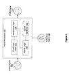
- Figure 1 illustrates one embodiment of a signal processor associated with estimating a natural sampling point from uniform sample points when generating a PWM signal.
- Figure 2 illustrates one embodiment of a method associated with estimating a natural sampling point from uniform sample points when generating a PWM signal.
- Figure 3 illustrates one example of identifying samples adjacent to a crossing point illustrated on a plot of an analog signal and a reference signal.
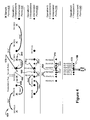
- Figure 4 illustrates one example of interpolating along an analog signal illustrated with multiple iterations of the interpolating.
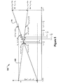
- Figure 5 illustrates one example of searching between interpolated points as illustrated on a plot of an analog signal and a reference signal.
- Figure 6 illustrates a comparison of a PWM output against a plot of an analog signal and a reference signal.
- Figure 7 illustrates a plot of a PWM output in the amplitude and frequency domains.
- Figure 8 illustrates one embodiment of an integrated circuit associated with estimating a natural sampling point from uniform sample points when generating a PWM signal.
- the natural sampling point (also referred to as NASP) is a point where an analog input signal intersects or crosses a reference signal. That is, when the analog signal and reference signal are plotted together on a graph, the NASP is the point where the two signals have the same value, and thus intersect.
- the NASP is used by natural sampling pulse width modulation (NPWM) to determine a width of a pulse in a PWM signal.
- NPWM uses the continuous analog signal, not just samples, in order to identify the NASP.
- NPWM suffers from difficulties with intermodulation spectral distortion.
- UPWM uniform sampling pulse-width modulation
- UPWM uses discrete samples of the analog signal instead of the continuous analog signal.
- the discrete samples do not always provide an accurate approximation of the NASP.
- UPWM is not as accurate and suffers from difficulties with in-band harmonic distortion.
- a signal processor is configured to use discrete samples of the analog signal to estimate the NASP. In this way, the signal processor can determine a more accurate representation of the NASP without using the continuous analog signal and also avoids difficulties with intermodulation spectral distortion and in-band harmonic distortion.
- a signal processor 100 is shown that is associated with estimating a natural sampling point (NASP) when generating pulses in a PWM signal 110.
- the signal processor 100 includes cross point logic 120, interpolation logic 130, search logic 140, and a signal generator 150.
- the signal processor 100 receives an analog signal 160 and a reference signal 170 as input.
- the analog signal 160 is, for example, an audio signal, control signal, or another analog signal that is to be converted to a digital form using pulse-width modulation (PWM).
- the reference signal 170 is a triangular waveform or saw tooth carrier waveform that is periodic and reoccurring, and is used by the signal processor 100 as a reference value when determining a value of the analog signal 160. While the analog signal 160 and the reference signal 170 are discussed as inputs to the signal processor 100, continuous values of the signals 160 and 170 are not used by the signal processor 100. Instead, in one embodiment, the cross point logic 120 is configured to sample the signals 160 and 170 at discrete points in time. In this way, the signal processor 100 does not use buffer/storage space for the whole signals 160 and 170, but only the samples.
- the samples are, for example, discrete points along one or both of the signals 160 and 170 that are represented by an amplitude value (e.g., volts or decibels).
- the samples can be normalized in order to compare the two signals 160 and 170 on a plot.
- the cross point logic 120 is configured to use the samples of the analog signal 160 to determine a likely location of a crossing point.
- the crossing point is a point where the analog signal 160 intersects the reference signal 170. That is, the cross point logic 120 determines which of the samples along the analog signal 160 are adjacent to the crossing point. For example, the cross point logic 120 identifies two samples that are adjacent to the reference signal 170 on either side.
- the cross point logic 120 iteratively subtracts a value of each sample of the analog signal 160 from a value of each corresponding sample of the reference signal 170. In general, corresponding samples are those samples taken at a same discrete time.
- the cross point logic 120 identifies a change in polarity between results, then the two adjacent samples have been identified (e.g., subtracting two previous samples provides a positive value while subtracting two current samples provides a negative value).
- the change in polarity indicates that the signals 160 and 170 have crossed and thus the crossing point occurs between the two samples.
- the cross point logic 120 narrows a region in which to interpolate values and search for the crossing point.
- the interpolation logic 130 is configured to interpolate points along the analog signal 160 that approach the crossing point.
- the interpolation logic 130 uses the two samples identified by the crossing point logic 120 as a starting point for interpolating. Accordingly, the interpolation logic 130 produces additional points along the analog signal 160 that are closer to the crossing point than the original samples of the analog signal 160.
- the interpolation logic 130 is configured to iteratively interpolate points along the analog signal 160 in multiple rounds until, for example, the interpolated points satisfy a predetermined condition (e.g., are within a certain range of the crossing point, or having performed a predetermined number of interpolations). In this way, the interpolation logic 130 is configured to interpolate the points to refine a region between the points within which the crossing point occurs.
- the interpolation logic 130 can be configured to use different algorithms to interpolate the points.
- the interpolation logic 130 can be configured to interpolate using Lagrange interpolation, Hermite interpolation, linear interpolation, cubic spline interpolation, and so on.
- the search logic 140 is configured to search within the refined region defined by the interpolated points. Consequently, the search logic 130 can focus a search on the refined region and therefore produce a more accurate estimate of a location of the crossing point.
- the search logic 140 is configured to perform a binary search or other search within the region bounded by the interpolated points to produce the estimated location of the crossing point. Accordingly, the search logic 140 is not, for example, searching within an entire period of the reference signal 170, but only the refined region which is limited to a space nearest to the crossing point.
- the search logic 140 produces an accurate estimate of the location of the crossing point by using the uniform discrete samples of the analog signal 160.
- the signal processor 100 avoids difficulties encountered by other methods that use discrete samples by, for example, refining the samples to further estimate the location of the crossing point to produce the PWM signal 110, thus, using a point that closely approximates the NASP.
- the signal generator 150 generates a pulse in a pulse train of the PWM signal 110 as a function of the estimated location of the crossing point. That is, the signal generator 150 generates the pulse with a width that is based on the estimated location of the crossing point. For example, consider that the reference signal 170 is a constantly repeating signal with a positive slope. From a beginning point of each period of the reference signal 170, the reference signal gradually increases in value. Eventually, the analog signal 160 intersects the reference signal 170 at the crossing point, which is a distance D (in units of time) from the beginning point of a given period of the reference signal 170. The signal generator 150 is configured to generate the pulse with a width (e.g., a duty cycle) that is, for example, equal to the distance D.
- a width e.g., a duty cycle
- the signal generator 150 generates the pulse according to a 3-level PWM scheme, a leading edge scheme, a trailing edge scheme, a centered edges scheme, or another method of generating pulses of a pulse-width modulation signal, In either case, the signal generator 150 generates pulses in a pulse train of the PWM signal as a function of the estimated locations of the crossing points. Accordingly, the signal processor 100 iteratively estimates crossing points and generates pulses to form the pulse train of the PWM signal 110.
- Figure 2 illustrates a method 200 associated with estimating a natural sampling point (NASP) from uniform sample points when generating a PWM signal.
- NSP natural sampling point
- the method 200 will be discussed from the perspective of the signal processor 100. Additionally, the method 200 will be discussed along with examples illustrated in Figures 3-7 .
- the method 200 begins at 210 when the signal processor 100 samples an analog signal (e.g., the analog signal 160).
- the samples are discrete samples that occur at uniform periods in time (e.g., every microsecond).
- the signal processor 100 can also sample a reference signal (e.g., the reference signal 170) using the same uniform period in order to provide samples of the reference signal that correspond in time to samples of the analog signal.
- the signal processor 100 stores the samples in buffers to await further processing.
- Figure 3 illustrates a plot 300 of time (x-axis) vs magnitude (y-axis) that includes samples of a reference signal 170 (i.e., S 0 -S 10 ) and samples of an analog signal 160 (i.e., X 0 -X 10 ).
- the samples occur according to a uniform interval for each of the signals,
- a sample frequency is f s ⁇ 1 f s 1
- Figure 3 also illustrates a period of the reference signal 170, which is given by 1 f pwm .
- f pwm is a frequency of the PWM signal 110.
- a number of samples per period of the reference signal (TR) can be represented as follows.
- the signal processor 100 determines which of the samples (from 210) along the analog signal 160 are adjacent to an intersection (i.e., crossing point 315) of the reference signal 170 and the analog signal 160.
- the signal processor 100 begins by comparing X 0 and S 0 to find ⁇ xs ii , which is further defined below.
- ⁇ xs ii will have a positive value.
- the signal processor 100 iteratively continues through the samples (e.g., X 1,.i and S 1.,i ) until finding a change in polarity (i.e., a negative value).
- the change in polarity occurs from X 2 , S 2 to X 3 , S 3 since the crossing point 315 occurs between these samples.
- the change in polarity indicates that the analog signal 160 has crossed over the reference signal 170 since a previous comparison.
- the signal processor 100 can identify a general region of the crossing point by identifying two samples (i.e., a left sample and a right sample) between which the crossing point occurs.
- the following pseudo code provides an example of how the method 200 may proceed at 220 through comparing the sample points.
- the signal processor 100 adaptively interpolates (e,g., adaptively upsamples) points along the analog signal 160 that approach the crossing point 315.
- the signal processor 100 uses, for example, the two samples determined at 220 to adaptively interpolate additional points along the analog signal 160. In this way, the signal processor 100 interpolates the points to refine a region between the points between which the crossing point 315 occurs.
- the signal processor 100 uses other samples in addition to the two samples. For example, depending on a type of interpolation (e.g., 4 pt. Hermite interpolation, spline Interpolation, etc.) employed by the signal processor 100, a different number of points may be used for each iteration of the interpolation. Accordingly, the signal processor 100 may use not only the two samples that are adjacent to the crossing point but also other samples that are further from the crossing point for a first round of interpolating. In this way, points interpolated by the signal processor 100 have a greater accuracy.
- a type of interpolation e.g., 4 pt. Hermite interpolation, spline Interpolation, etc.
- Figure 4 illustrates multiple adaptive interpolation operations 400.
- Sample points 405 are the samples from 210 of the method 200.
- the two samples, X low 410 and X high 415, are the two adjacent samples along the analog signal 160 that are nearest to the crossing point with the reference signal 170.
- Interpolation operation1 four of the sample points 405 are used, including the two adjacent samples 410 and 415 to produce interpolated points 430. In other embodiments, more of the sample points 405 are used or, for example, only the two adjacent samples 410 and 415 are used depending on a type of interpolation implemented.
- Figure 4 illustrates a four point Hermite interpolation, Accordingly, each interpolation operation 1-4 uses four points as input to interpolate each additional point.
- the input points, for example, in the first operation 430 are all sample points 405 from 210 of the method 200.
- operations 2-4 may primarily use interpolated points from a previous operation. That is, the operations 2-4 may use one or more of the sample points 405 if, for example, those sample points are closer to the crossing point than interpolated points from a previous operation.
- the signal processor 100 adaptively selects points to store for a next interpolation operation by moving points between buffers and by storing interpolated points into buffers if, for example, the new interpolated points are closer than the samples and any previously interpolated points. In this way, the signal processor 100 uses less storage space when adaptively interpolating.
- a number of buffers implemented can vary depending on a type of interpolation performed.
- the operations 2-4 primarily use interpolated points (e.g., 430-440) from previous operations, however, if, for example, the interpolated points do not improve (e.g., closer) over previous points then the signal processor 100 adaptively selects the closer points when interpolating to avoid saving points that do not refine the region.
- operation 1 interpolates three new points 430 by using four of the sample points 405 for each interpolation.
- Operation 2 uses three of the original samples points 405 and the three interpolated points 430 from operation 1 to interpolate another three new points 435.
- Figure 4 illustrates arrows between points at each operation 1-4 to show how points are adaptively moved/overwritten between buffers of the signal processor 100 in order to save points for a next operation while points which are further from the crossing point are discarded.
- the signal processor 100 can prevent use of interpolated points or sample points that are further from the crossing point than other points and not waste resources on storing points that do not improve refining the region.
- the signal processor 100 uses the three points 435 from operation 2 as well as other points (e.g., previously interpolated points and/or sample points) to interpolate two points 440.
- points e.g., previously interpolated points and/or sample points
- only two interpolations occur even though three points are shown. Only two points are interpolated while three are shown because as the signal processor 100 refines a region in which the crossing point occurs, only those points on one side of a closest point are interpolated. That is, for example, if a closest point is to the left of the reference signal 170 then only points to the right of the closest point are interpolated since points to the left of the closest point will be further from the reference signal 170. In this way, the signal processor 100 adaptively interpolates to focus interpolating on a region directly around the crossing point. Additionally, by focusing the interpolating in this way a number of calculations can be reduced thereby improving efficiency of interpolating.
- the signal processor 100 only interpolates one point for similar reasons as in operation 3. Points 445 result from the interpolation 400 and define outrebounds of a refined region within which the crossing point occurs. In this way, the signal processor 100 defines the refined region using an efficient number of calculations and an efficient amount of storage space by adaptively storing, for example, interpolated/sam pled points only when they are useful for a next round of interpolating and by adaptively focusing interpolating operations toward a region of the crossing point to improve a number of calculations.
- the signal processor 100 searches within the refined region as defined by the points 445.
- the signal processor 100 produces an estimated location of the crossing point by searching between the interpolated points from 230.
- Figure 5 illustrates a plot 500 of the refined region determined at 230 and as defined by the two points that result from 230.
- x0 is Xlow and x17 is Xhigh from 230. That is, x0 is a point along the analog signal 160 that is closest on a left side of the reference signal 170, and x17 is a point on the analog signal 160 that is closest on a right side of the reference signal 170, as determined at 230.
- Figure 5 illustrates a binary search with sixteen iterations that occur between Xlow and Xhigh. The binary search illustrated in Figure 5 estimates a location of the crossing point (i.e., the NASP).
- Equation (6) illustrates a loop executed by the signal processor 100 to perform the binary search.
- the binary search is performed sixteen times by the signal processor 100.
- the signal processor 100 performs the binary search until, for example, reaching a predetermined number of iterations or until a result of the search is within a predetermined distance of the crossing point.
- the signal processor 100 may implement other searches to generate the estimated location of the crossing point.
- the signal processor 100 can implement a dichotomic search or other search algorithm that is designed to search within a specified location of a plot of two signals to find an intersection point.
- the signal processor 100 generates a pulse in a pulse train of the PWM signal 110 as a function of the estimated location of the crossing point.
- the signal processor 100 generates the pulse with a width that is based on the estimated location of the crossing point. For example, the signal processor 100 generates the pulse beginning at a beginning point of a period of the reference signal 170. The signal processor 100 maintains the pulse until, for example, reaching the estimated location of the crossing point in the period of the reference signal 170. In this way, the signal processor 100 generates the pulse with a width that is a function of where the estimated location of the crossing point occurs.
- the signal processor 100 generates pulses in the PWM signal 110 according to a three-level pulse-width modulation or other pulse-width modulation scheme. Thus, pulses of the PWM signal 110 can have a positive or negative amplitude.
- Figure 6 illustrates one example of a plot 600 of the analog signal 160 and the reference signal 170.
- a PWM output 605 (e..g, the PWM signal 110) is generated by the signal processor 100 in accordance with a three-level PWM scheme.
- the signal processor 100 generates the PWM output 605 to have a negative value (e.g., pulse 620) when the analog signal 160 is below a predefined amplitude (e.g., ⁇ 0) and to have a positive value (e.g., pulse 625) when the analog signal 160 has an amplitude above the predefined amplitude (e.g., >0).
- Figure 7 illustrates a plot 700 of a PWM output 705 (e.g., the PWM signal 110) in the amplitude (y-axis) and frequency (x-axis) domains.
- a PWM output 705 e.g., the PWM signal 110
- Figure 8 illustrates an additional embodiment of the signal processor 100 from Figure 1 that is configured with separate integrated circuits and/or chips.
- the cross point logic 120 from Figure 1 is embodied as a separate integrated circuit 810.
- the interpolation logic 130, the search logic 140, and the signal generator 150 are embodied as separate integrated circuits 820-840.
- the integrated circuits 810-840 are connected via connection paths to communicate signals. While integrated circuits 810, 820, 830 and 840 are illustrated as separate integrated circuits, they may be integrated into a common integrated circuit board 800. Additionally, integrated circuits 810, 820, 830, and 840 may be combined into fewer integrated circuits or divided into more integrated circuits than illustrated.
- cross point logic 120, the interpolation logic 130, and the search logic 140 illustrated in integrated circuits 810, 820, and 830 may be combined into a separate application specific integrated circuit (ASIC).
- ASIC application specific integrated circuit
- portions of the functionality associated with the cross point logic 120, the interpolation logic 130, and the search logic 140 may be embodied as firmware executable by a processor and stored in a non-transitory memory.
- references to "one embodiment”, “an embodiment”, “one example”, “an example”, and so on, indicate that the embodiment(s) or example(s) so described may include a particular feature, structure, characteristic, property, element, or limitation, but that not every embodiment or example necessarily includes that particular feature, structure, characteristic, property, element or limitation. Furthermore, repeated use of the phrase “in one embodiment” does not necessarily refer to the same embodiment, though it may.
- Logic includes a computer or electrical hardware component(s), firmware, a non-transitory computer readable medium that stores instructions, and/or combinations of these components configured to perform a function(s) or an action(s), and/or to cause a function or action from another logic, method, and/or system.
- Logic may include a microprocessor controlled by an algorithm to perform one or more of the disclosed functions/methods, a discrete logic (e.g., ASIC), an analog circuit, a digital circuit, a programmed logic device, a memory device containing instructions, and so on.
- Logic may include one or more gates, combinations of gates, or other circuit components. Where multiple logics are described, it may be possible to incorporate the multiple logics into one physical logic component. Similarly, where a single logic component is described, it may be possible to distribute that single logic component between multiple physical logic components. In some embodiments, one or more of the components and functions described herein are implemented using one or more of the logic components.
- illustrated methodologies are shown and described as a series of blocks. The methodologies are not limited by the order of the blocks as some blocks can occur in different orders and/or concurrently with other blocks from that shown and described. Moreover, less than all the illustrated blocks may be used to implement an example methodology. Blocks may be combined or separated into multiple components. Furthermore, additional and/or alternative methodologies can employ additional, not illustrated blocks.
Landscapes
- Analogue/Digital Conversion (AREA)
Abstract
Description
- This patent disclosure claims the benefit of
U.S. provisional application serial No. 61/610,749 filed on March 14, 2012 - The background description provided herein is for the purpose of generally presenting the context of the disclosure. Work of the presently named inventor(s), to the extent the work is described in this background section, as well as aspects of the description that may not otherwise qualify as prior art at the time of filing, are neither expressly nor impliediy admitted as prior art against the present disclosure.
- Pulse-width modulation (PWM) refers to a technique of generating a signal by a digital device. For example, the digital device may iteratively vary or modulate a duty cycle of a square wave in order to approximate an analog signal. PWM is, in general, an efficient way of producing a signal that avoids, for example, excessive power loss. Furthermore, different techniques may be used to generate a PWM signal. However, each technique may suffer from different difficulties, such as interference or reduced accuracy.
- In general, in one aspect this specification discloses an apparatus for generating a pulse width modulation (PWM) signal using samples of an analog signal. The apparatus includes a cross point logic configured to determine which of the samples along the analog signal are adjacent to a crossing point of a reference signal and the analog signal by identifying samples between which the crossing point occurs. The crossing point is a point where the analog signal intersects the reference signal. The apparatus includes an interpolation logic configured to adaptively interpolate points along the analog signal that approach the crossing point by using the samples. The interpolation logic is configured to adaptively interpolate the points to refine a region between the points within which the crossing point occurs. The apparatus includes a search logic configured to search within the region to produce an estimated location of the crossing point by using the interpolated points. The apparatus includes a signal generator configured to generate a pulse in a pulse train of the PWM signal as a function of the estimated location of the crossing point.
- In another embodiment, the signal generator is configured to generate the pulse by generating the pulse with a width that is based on the estimated location of the crossing point.
- In another embodiment, the search logic is configured to search the region using a binary search algorithm to produce the estimated location. The search logic is configured to search the region by using the binary search algorithm to search within the region until the estimate of the location satisfies a predetermined condition. The predetermined condition defines a number of iterations for the binary search algorithm.
- In general, in another aspect, this specification discloses a method for generating a pulse width modulation (PWM) signal using samples of an analog signal. The method includes determining, by a signal processor, which of the samples along the analog signal are adjacent to a crossing point of a reference signal and the analog signal by identifying samples between which the crossing point occurs. The crossing point is a point where the analog signal intersects the reference signal. The method includes adaptively interpolating points along the analog signal that approach the crossing point by using the samples. Adaptively interpolating the points refines a region between the points within which the crossing point occurs. The method includes searching within the region to produce an estimated location of the crossing point by using the interpolated points. The method includes generating a pulse in a pulse train of the PWM signal as a function of the estimated location of the crossing point.
- In general, in another aspect, this specification discloses a non-transitory computer-readable medium that when executed by a computer cause the computer to perform a method. The method includes analyzing samples of an analog signal. The method includes adaptively interpolating, by a signal processor in the computer, points along the analog signal that approach a crossing point. Adaptively interpolating the points uses samples that are adjacent to a reference signal along the analog signal to refine a region between the points within which the crossing point occurs. The crossing point is a point where the analog signal intersects the reference signal. The method includes searching within the region to produce an estimated location of the crossing point by using the interpolated points.
- The accompanying drawings, which are incorporated in and constitute a part of the specification, illustrate various systems, methods, and other embodiments of the disclosure. Illustrated element boundaries (e.g., boxes, groups of boxes, or other shapes) in the figures represent one example of the boundaries. In some examples one element may be designed as multiple elements or multiple elements may be designed as one element. In some examples, an element shown as an internal component of another element may be implemented as an external component and vice versa.
-
Figure 1 illustrates one embodiment of a signal processor associated with estimating a natural sampling point from uniform sample points when generating a PWM signal. -
Figure 2 illustrates one embodiment of a method associated with estimating a natural sampling point from uniform sample points when generating a PWM signal. -
Figure 3 illustrates one example of identifying samples adjacent to a crossing point illustrated on a plot of an analog signal and a reference signal. -
Figure 4 illustrates one example of interpolating along an analog signal illustrated with multiple iterations of the interpolating. -
Figure 5 illustrates one example of searching between interpolated points as illustrated on a plot of an analog signal and a reference signal. -
Figure 6 illustrates a comparison of a PWM output against a plot of an analog signal and a reference signal. -
Figure 7 illustrates a plot of a PWM output in the amplitude and frequency domains. -
Figure 8 illustrates one embodiment of an integrated circuit associated with estimating a natural sampling point from uniform sample points when generating a PWM signal. - Described herein are examples of systems, methods, and other embodiments associated with estimating a natural sampling point to generate a pulse of a PWM signal. The natural sampling point (also referred to as NASP) is a point where an analog input signal intersects or crosses a reference signal. That is, when the analog signal and reference signal are plotted together on a graph, the NASP is the point where the two signals have the same value, and thus intersect. The NASP is used by natural sampling pulse width modulation (NPWM) to determine a width of a pulse in a PWM signal. However, NPWM uses the continuous analog signal, not just samples, in order to identify the NASP. Thus, to perform NPWM the continuous analog signal needs to be available. Additionally, NPWM suffers from difficulties with intermodulation spectral distortion.
- Another technique for sampling in PWM is uniform sampling pulse-width modulation (UPWM). UPWM uses discrete samples of the analog signal instead of the continuous analog signal. However, the discrete samples do not always provide an accurate approximation of the NASP. Accordingly, UPWM is not as accurate and suffers from difficulties with in-band harmonic distortion. Thus, in one embodiment, a signal processor is configured to use discrete samples of the analog signal to estimate the NASP. In this way, the signal processor can determine a more accurate representation of the NASP without using the continuous analog signal and also avoids difficulties with intermodulation spectral distortion and in-band harmonic distortion.
- With reference to
Figure 1 , one embodiment of asignal processor 100 is shown that is associated with estimating a natural sampling point (NASP) when generating pulses in aPWM signal 110. Thesignal processor 100 includescross point logic 120,interpolation logic 130,search logic 140, and asignal generator 150. Thesignal processor 100 receives ananalog signal 160 and areference signal 170 as input. - The
analog signal 160 is, for example, an audio signal, control signal, or another analog signal that is to be converted to a digital form using pulse-width modulation (PWM). Thereference signal 170 is a triangular waveform or saw tooth carrier waveform that is periodic and reoccurring, and is used by thesignal processor 100 as a reference value when determining a value of theanalog signal 160. While theanalog signal 160 and thereference signal 170 are discussed as inputs to thesignal processor 100, continuous values of thesignals signal processor 100. Instead, in one embodiment, thecross point logic 120 is configured to sample thesignals signal processor 100 does not use buffer/storage space for thewhole signals - The samples are, for example, discrete points along one or both of the
signals signals - In one embodiment, the
cross point logic 120 is configured to use the samples of theanalog signal 160 to determine a likely location of a crossing point. The crossing point is a point where theanalog signal 160 intersects thereference signal 170. That is, thecross point logic 120 determines which of the samples along theanalog signal 160 are adjacent to the crossing point. For example, thecross point logic 120 identifies two samples that are adjacent to thereference signal 170 on either side. Thecross point logic 120 iteratively subtracts a value of each sample of theanalog signal 160 from a value of each corresponding sample of thereference signal 170. In general, corresponding samples are those samples taken at a same discrete time. When thecross point logic 120 identifies a change in polarity between results, then the two adjacent samples have been identified (e.g., subtracting two previous samples provides a positive value while subtracting two current samples provides a negative value). The change in polarity indicates that thesignals analog signal 160 that are adjacent to referencesignal 170, thecross point logic 120 narrows a region in which to interpolate values and search for the crossing point. - For example, once the two adjacent samples are identified the
interpolation logic 130 is configured to interpolate points along theanalog signal 160 that approach the crossing point. Theinterpolation logic 130 uses the two samples identified by thecrossing point logic 120 as a starting point for interpolating. Accordingly, theinterpolation logic 130 produces additional points along theanalog signal 160 that are closer to the crossing point than the original samples of theanalog signal 160. In one embodiment, theinterpolation logic 130 is configured to iteratively interpolate points along theanalog signal 160 in multiple rounds until, for example, the interpolated points satisfy a predetermined condition (e.g., are within a certain range of the crossing point, or having performed a predetermined number of interpolations). In this way, theinterpolation logic 130 is configured to interpolate the points to refine a region between the points within which the crossing point occurs. - The
interpolation logic 130 can be configured to use different algorithms to interpolate the points. For example, theinterpolation logic 130 can be configured to interpolate using Lagrange interpolation, Hermite interpolation, linear interpolation, cubic spline interpolation, and so on. - After the
interpolation logic 130 has interpolated the points, thesearch logic 140 is configured to search within the refined region defined by the interpolated points. Consequently, thesearch logic 130 can focus a search on the refined region and therefore produce a more accurate estimate of a location of the crossing point. For example, thesearch logic 140 is configured to perform a binary search or other search within the region bounded by the interpolated points to produce the estimated location of the crossing point. Accordingly, thesearch logic 140 is not, for example, searching within an entire period of thereference signal 170, but only the refined region which is limited to a space nearest to the crossing point. - In this way, the
search logic 140 produces an accurate estimate of the location of the crossing point by using the uniform discrete samples of theanalog signal 160. However, thesignal processor 100 avoids difficulties encountered by other methods that use discrete samples by, for example, refining the samples to further estimate the location of the crossing point to produce thePWM signal 110, thus, using a point that closely approximates the NASP. - Once the
search logic 140 produces the estimate of the location of the crossing point (i.e., the NASP), thesignal generator 150 generates a pulse in a pulse train of the PWM signal 110 as a function of the estimated location of the crossing point. That is, thesignal generator 150 generates the pulse with a width that is based on the estimated location of the crossing point. For example, consider that thereference signal 170 is a constantly repeating signal with a positive slope. From a beginning point of each period of thereference signal 170, the reference signal gradually increases in value. Eventually, theanalog signal 160 intersects thereference signal 170 at the crossing point, which is a distance D (in units of time) from the beginning point of a given period of thereference signal 170. Thesignal generator 150 is configured to generate the pulse with a width (e.g., a duty cycle) that is, for example, equal to the distance D. - In one embodiment, the
signal generator 150 generates the pulse according to a 3-level PWM scheme, a leading edge scheme, a trailing edge scheme, a centered edges scheme, or another method of generating pulses of a pulse-width modulation signal, In either case, thesignal generator 150 generates pulses in a pulse train of the PWM signal as a function of the estimated locations of the crossing points. Accordingly, thesignal processor 100 iteratively estimates crossing points and generates pulses to form the pulse train of thePWM signal 110. - Further details of the
signal processor 100 and estimating the crossing point will be discussed with relation toFigure 2. Figure 2 illustrates amethod 200 associated with estimating a natural sampling point (NASP) from uniform sample points when generating a PWM signal. For purposes of this discussion, themethod 200 will be discussed from the perspective of thesignal processor 100. Additionally, themethod 200 will be discussed along with examples illustrated inFigures 3-7 . - The
method 200 begins at 210 when thesignal processor 100 samples an analog signal (e.g., the analog signal 160). The samples are discrete samples that occur at uniform periods in time (e.g., every microsecond). Thesignal processor 100 can also sample a reference signal (e.g., the reference signal 170) using the same uniform period in order to provide samples of the reference signal that correspond in time to samples of the analog signal. In one embodiment, thesignal processor 100 stores the samples in buffers to await further processing. -
Figure 3 illustrates aplot 300 of time (x-axis) vs magnitude (y-axis) that includes samples of a reference signal 170 (i.e., S0-S10) and samples of an analog signal 160 (i.e., X0-X10). As seen inFigure 3 , the samples occur according to a uniform interval for each of the signals, For example, as illustrated inFigure 3 , a sample frequency is
Figure 3 also illustrates a period of thereference signal 170, which is given by
PWM signal 110. A number of samples per period of the reference signal (TR) can be represented as follows.


- Continuing with
Figure 2 and themethod 200, at 220, thesignal processor 100 determines which of the samples (from 210) along theanalog signal 160 are adjacent to an intersection (i.e., crossing point 315) of thereference signal 170 and theanalog signal 160. As an example, further considerFigure 3 . Forsaw 1, thesignal processor 100 begins by comparing X0 and S0 to find Δxsii, which is further defined below. For X0 and S0, Δxsii will have a positive value. Accordingly, thesignal processor 100 iteratively continues through the samples (e.g., X1,.i and S1.,i) until finding a change in polarity (i.e., a negative value). InFigure 3 , the change in polarity occurs from X2, S2 to X3, S3 since thecrossing point 315 occurs between these samples. The change in polarity indicates that theanalog signal 160 has crossed over thereference signal 170 since a previous comparison. In this way, thesignal processor 100 can identify a general region of the crossing point by identifying two samples (i.e., a left sample and a right sample) between which the crossing point occurs. - The following pseudo code provides an example of how the
method 200 may proceed at 220 through comparing the sample points.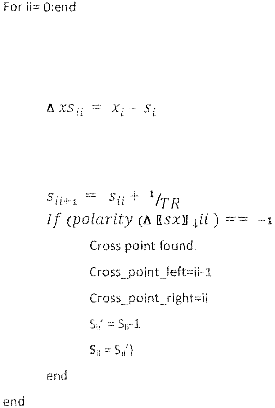
- Continuing with the
method 200 ofFigure 2 , at 230 thesignal processor 100 adaptively interpolates (e,g., adaptively upsamples) points along theanalog signal 160 that approach thecrossing point 315. Thesignal processor 100 uses, for example, the two samples determined at 220 to adaptively interpolate additional points along theanalog signal 160. In this way, thesignal processor 100 interpolates the points to refine a region between the points between which thecrossing point 315 occurs. - Furthermore, in one embodiment, the
signal processor 100 uses other samples in addition to the two samples. For example, depending on a type of interpolation (e.g., 4 pt. Hermite interpolation, spline Interpolation, etc.) employed by thesignal processor 100, a different number of points may be used for each iteration of the interpolation. Accordingly, thesignal processor 100 may use not only the two samples that are adjacent to the crossing point but also other samples that are further from the crossing point for a first round of interpolating. In this way, points interpolated by thesignal processor 100 have a greater accuracy. - For example,
Figure 4 illustrates multipleadaptive interpolation operations 400. Sample points 405 are the samples from 210 of themethod 200. The two samples,X low 410 andX high 415, are the two adjacent samples along theanalog signal 160 that are nearest to the crossing point with thereference signal 170. At Interpolation operation1, four of the sample points 405 are used, including the twoadjacent samples adjacent samples Figure 4 illustrates a four point Hermite interpolation, Accordingly, each interpolation operation 1-4 uses four points as input to interpolate each additional point. The input points, for example, in the first operation 430 are all sample points 405 from 210 of themethod 200. However, operations 2-4 may primarily use interpolated points from a previous operation. That is, the operations 2-4 may use one or more of the sample points 405 if, for example, those sample points are closer to the crossing point than interpolated points from a previous operation. For example, thesignal processor 100 adaptively selects points to store for a next interpolation operation by moving points between buffers and by storing interpolated points into buffers if, for example, the new interpolated points are closer than the samples and any previously interpolated points. In this way, thesignal processor 100 uses less storage space when adaptively interpolating. Of course, a number of buffers implemented can vary depending on a type of interpolation performed. In general, the operations 2-4 primarily use interpolated points (e.g., 430-440) from previous operations, however, if, for example, the interpolated points do not improve (e.g., closer) over previous points then thesignal processor 100 adaptively selects the closer points when interpolating to avoid saving points that do not refine the region. - For example,
operation 1 interpolates three new points 430 by using four of the sample points 405 for each interpolation.Operation 2 uses three of the original samples points 405 and the three interpolated points 430 fromoperation 1 to interpolate another three new points 435.Figure 4 illustrates arrows between points at each operation 1-4 to show how points are adaptively moved/overwritten between buffers of thesignal processor 100 in order to save points for a next operation while points which are further from the crossing point are discarded. In this way, thesignal processor 100 can prevent use of interpolated points or sample points that are further from the crossing point than other points and not waste resources on storing points that do not improve refining the region. - At
operation 3, thesignal processor 100 uses the three points 435 fromoperation 2 as well as other points (e.g., previously interpolated points and/or sample points) to interpolate two points 440. Atoperation 3, only two interpolations occur even though three points are shown. Only two points are interpolated while three are shown because as thesignal processor 100 refines a region in which the crossing point occurs, only those points on one side of a closest point are interpolated. That is, for example, if a closest point is to the left of thereference signal 170 then only points to the right of the closest point are interpolated since points to the left of the closest point will be further from thereference signal 170. In this way, thesignal processor 100 adaptively interpolates to focus interpolating on a region directly around the crossing point. Additionally, by focusing the interpolating in this way a number of calculations can be reduced thereby improving efficiency of interpolating. - At
operation 4, thesignal processor 100 only interpolates one point for similar reasons as inoperation 3. Points 445 result from theinterpolation 400 and define outrebounds of a refined region within which the crossing point occurs. In this way, thesignal processor 100 defines the refined region using an efficient number of calculations and an efficient amount of storage space by adaptively storing, for example, interpolated/sam pled points only when they are useful for a next round of interpolating and by adaptively focusing interpolating operations toward a region of the crossing point to improve a number of calculations. - Continuing with the
method 200 ofFigure 2 , at 240, thesignal processor 100 searches within the refined region as defined by the points 445. Thesignal processor 100 produces an estimated location of the crossing point by searching between the interpolated points from 230. - Consider
Figure 5 , which illustrates aplot 500 of the refined region determined at 230 and as defined by the two points that result from 230. InFigure 5 , x0 is Xlow and x17 is Xhigh from 230. That is, x0 is a point along theanalog signal 160 that is closest on a left side of thereference signal 170, and x17 is a point on theanalog signal 160 that is closest on a right side of thereference signal 170, as determined at 230. Accordingly,Figure 5 illustrates a binary search with sixteen iterations that occur between Xlow and Xhigh. The binary search illustrated inFigure 5 estimates a location of the crossing point (i.e., the NASP). The binary search illustrated inFigure 5 operates according to the following: (Note that "sign" is used in the following equations to denote polarity and not the trigonometric function sine)


- Equation (6) illustrates a loop executed by the
signal processor 100 to perform the binary search. Four example iterations of the loop are shown below:


- The binary search, as shown in
Figure 5 , is performed sixteen times by thesignal processor 100. In general, thesignal processor 100 performs the binary search until, for example, reaching a predetermined number of iterations or until a result of the search is within a predetermined distance of the crossing point. An estimated location of the crossing point inFigure 5 is given by the following:
- While
Figure 5 illustrate a binary search, of course, thesignal processor 100 may implement other searches to generate the estimated location of the crossing point. For example, thesignal processor 100 can implement a dichotomic search or other search algorithm that is designed to search within a specified location of a plot of two signals to find an intersection point. - Continuing with the
method 200 ofFigure 2 , at 250, thesignal processor 100 generates a pulse in a pulse train of the PWM signal 110 as a function of the estimated location of the crossing point. In one embodiment, thesignal processor 100 generates the pulse with a width that is based on the estimated location of the crossing point. For example, thesignal processor 100 generates the pulse beginning at a beginning point of a period of thereference signal 170. Thesignal processor 100 maintains the pulse until, for example, reaching the estimated location of the crossing point in the period of thereference signal 170. In this way, thesignal processor 100 generates the pulse with a width that is a function of where the estimated location of the crossing point occurs. In one embodiment, thesignal processor 100 generates pulses in the PWM signal 110 according to a three-level pulse-width modulation or other pulse-width modulation scheme. Thus, pulses of the PWM signal 110 can have a positive or negative amplitude. -
Figure 6 illustrates one example of aplot 600 of theanalog signal 160 and thereference signal 170. InFigure 6 , a PWM output 605 (e..g, the PWM signal 110) is generated by thesignal processor 100 in accordance with a three-level PWM scheme. For example, thesignal processor 100 generates thePWM output 605 to have a negative value (e.g., pulse 620) when theanalog signal 160 is below a predefined amplitude (e.g., <0) and to have a positive value (e.g., pulse 625) when theanalog signal 160 has an amplitude above the predefined amplitude (e.g., >0). - In this way, the
signal processor 100 produces an accurate digital version of theanalog signal 160 without producing, for example, intermodulation spectral distortion. For example,Figure 7 illustrates aplot 700 of a PWM output 705 (e.g., the PWM signal 110) in the amplitude (y-axis) and frequency (x-axis) domains. As shown inFigure 7 , there are no adjacent bands to thePWM output 705. This is because thePWM output 705 is generated by thesignal processor 100 and there is no distortion and thus no other bands on theplot 700. -
Figure 8 illustrates an additional embodiment of thesignal processor 100 fromFigure 1 that is configured with separate integrated circuits and/or chips. In this embodiment, thecross point logic 120 fromFigure 1 is embodied as a separateintegrated circuit 810. Additionally, theinterpolation logic 130, thesearch logic 140, and thesignal generator 150 are embodied as separate integrated circuits 820-840. The integrated circuits 810-840 are connected via connection paths to communicate signals. Whileintegrated circuits circuit board 800. Additionally,integrated circuits cross point logic 120, theinterpolation logic 130, and thesearch logic 140 illustrated inintegrated circuits cross point logic 120, theinterpolation logic 130, and thesearch logic 140 may be embodied as firmware executable by a processor and stored in a non-transitory memory. - The following includes definitions of selected terms employed herein. The definitions include various examples and/or forms of components that fall within the scope of a term and that may be used for implementation. The examples are not intended to be limiting. Both singular and plural forms of terms may be within the definitions.
- References to "one embodiment", "an embodiment", "one example", "an example", and so on, indicate that the embodiment(s) or example(s) so described may include a particular feature, structure, characteristic, property, element, or limitation, but that not every embodiment or example necessarily includes that particular feature, structure, characteristic, property, element or limitation. Furthermore, repeated use of the phrase "in one embodiment" does not necessarily refer to the same embodiment, though it may.
- "Logic", as used herein, includes a computer or electrical hardware component(s), firmware, a non-transitory computer readable medium that stores instructions, and/or combinations of these components configured to perform a function(s) or an action(s), and/or to cause a function or action from another logic, method, and/or system. Logic may include a microprocessor controlled by an algorithm to perform one or more of the disclosed functions/methods, a discrete logic (e.g., ASIC), an analog circuit, a digital circuit, a programmed logic device, a memory device containing instructions, and so on. Logic may include one or more gates, combinations of gates, or other circuit components. Where multiple logics are described, it may be possible to incorporate the multiple logics into one physical logic component. Similarly, where a single logic component is described, it may be possible to distribute that single logic component between multiple physical logic components. In some embodiments, one or more of the components and functions described herein are implemented using one or more of the logic components.
- While for purposes of simplicity of explanation, illustrated methodologies are shown and described as a series of blocks. The methodologies are not limited by the order of the blocks as some blocks can occur in different orders and/or concurrently with other blocks from that shown and described. Moreover, less than all the illustrated blocks may be used to implement an example methodology. Blocks may be combined or separated into multiple components. Furthermore, additional and/or alternative methodologies can employ additional, not illustrated blocks.
- To the extent that the term "includes" or "including" is employed in the detailed description or the claims, it is intended to be inclusive in a manner similar to the term "comprising" as that term is interpreted when employed as a transitional word in a claim.
- While example systems, methods, and so on have been illustrated by describing examples, and while the examples have been described in considerable detail, it is not the intention of the applicants to restrict or in any way limit the scope of the appended claims to such detail. It is, of course, not possible to describe every conceivable combination of components or methodologies for purposes of describing the systems, methods, and so on described herein. Therefore, the disclosure is not limited to the specific details, the representative apparatus, and illustrative examples shown and described. Thus, this application is intended to embrace alterations, modifications, and variations that fall within the scope of the appended claims.
The following is a list of further preferred embodiments of the invention: - Embodiment 1: An apparatus for generating a pulse width modulation (PWM) signal using samples of an analog signal, comprising:
- cross point logic configured to determine which of the samples along the analog signal are adjacent to a crossing point of a reference signal and the analog signal by identifying samples between which the crossing point occurs, wherein the crossing point is a point where the analog signal intersects the reference signal;
- an interpolation logic configured to adaptively interpolate points along the analog signal that approach the crossing point by using the samples, wherein the interpolation logic is configured to adaptively interpolate the points to refine a region between the points within which the crossing point occurs;
- search logic configured to search within the region to produce an estimated location of the crossing point by using the interpolated points; and
- a signal generator configured to generate a pulse in a pulse train of the PWM signal as a function of the estimated location of the crossing point.
- Embodiment 2: The apparatus of
embodiment 1, wherein the signal generator is configured to generate the pulse by generating the pulse with a width that is based on the estimated location of the crossing point. - Embodiment 3: The apparatus of
embodiment 1, wherein the search logic is configured to search the region using a binary search algorithm to produce the estimated location, wherein the search logic is configured to search the region by using the binary search algorithm to search within the region until the estimate of the location satisfies a predetermined condition, and wherein the predetermined condition defines a number of iterations for the binary search algorithm. - Embodiment 4: The apparatus of
embodiment 1, wherein the interpolation logic is configured to interpolate the points by iteratively interpolating a plurality of points until the points are within a predetermined distance of the crossing point. - Embodiment 5: The apparatus of
embodiment 1, wherein the cross point logic is configured to sample the analog signal at a uniform interval to generate the samples, wherein the estimated location of the crossing point is an estimate of a natural sampling point (NASP) of the analog signal. - Embodiment 6: The apparatus of
embodiment 1, wherein the interpolated points include two sample points along the analog signal that are on opposite sides of the reference signal and are located within a predetermined distance of the crossing point. - Embodiment 7: The apparatus of
embodiment 1, wherein the signal generator is configured to generate the PWM signal by generating the PWM signal using uniform PWM sampling to determine a natural sampling point of the analog signal, and wherein the analog signal is an audio signal. - Embodiment 8: A method for generating a pulse width modulation (PWM) signal using samples of an analog signal, the method comprising:
- determining, by a signal processor, which of the samples along the analog signal are adjacent to a crossing point of a reference signal and the analog signal by identifying samples between which the crossing point occurs, wherein the crossing point is a point where the analog signal intersects the reference signal;
- adaptively interpolating points along the analog signal that approach the crossing point by using the samples, wherein adaptively interpolating the points refines a region between the points within which the crossing point occurs;
- searching within the region to produce an estimated location of the crossing point by using the interpolated points; and
- generating a pulse in a pulse train of the PWM signal as a function of the estimated location of the crossing point.
- Embodiment 9: The method of
embodiment 8, wherein generating the pulse includes generating the pulse with a width that is based on the estimated location of the crossing point. - Embodiment 10: The method of
embodiment 8, wherein searching includes searching the region using a binary search algorithm to produce the estimated location, wherein searching includes performing the binary search within the region until the estimate of the location satisfies a predetermined condition, and wherein the predetermined condition defines a number of iterations for the binary search. - Embodiment 11: The method of
embodiment 8, wherein adaptively interpolating the points includes iteratively interpolating a plurality of points until interpolating the points that are within a predetermined distance of the crossing point. - Embodiment 12: The method of
embodiment 8, further comprising:- sampling the analog signal at a uniform interval to generate the samples, wherein the estimated location of the crossing point is an estimate of a natural sampling point (NASP) of the analog signal.
- Embodiment 13: The method of
embodiment 8, wherein the interpolated points include two sample points along the analog signal that are on opposite sides of the reference signal and are located within a predetermined distance of the crossing point. - Embodiment 14: The method of
embodiment 8, wherein generating the PWM signal includes generating the PWM signal using uniform PWM sampling to determine a natural sampling point of the analog signal. - Embodiment 15: The method of
embodiment 8, wherein the signal processor receives the reference signal as a saw-tooth carrier waveform and receives the analog signal as an audio signal.
- Embodiment 16: A non-transitory computer-readable medium storing computer executable instructions that when executed by a computer cause the computer to perform a method, the method comprising:
- analyzing samples of an analog signal;
- adaptively interpolating, by a signal processor in the computer, points along the analog signal that approach a crossing point, wherein adaptively interpolating the points uses samples that are adjacent to a reference signal along the analog signal to refine a region between the points within which the crossing point occurs, and wherein the crossing point is a point where the analog signal intersects the reference signal; and
- searching within the region to produce an estimated location of the crossing point by using the interpolated points.
- Embodiment 17: The non-transitory computer-readable medium of
embodiment 16,- determining, by the signal processor, which of the samples along the analog signal are adjacent to the crossing point of the reference signal and the analog signal by identifying samples of the samples between which the crossing point occurs.
- Embodiment 18: The non-transitory computer-readable medium of
embodiment 16, further comprising:- generating, by the signal processor, a pulse in a pulse train of a pulse-width modulation (PWM) signal as a function of the estimated location of the crossing point.
- Embodiment 19: The non-transitory computer-readable medium of
embodiment 16, further comprising:- sampling, prior to adaptively interpolating the points, the analog signal at a uniform interval to generate the samples.
- Embodiment 20: The non-transitory computer-readable medium of
embodiment 16, wherein the estimated location of the crossing point is an estimate of a natural sampling point (NASP) of the analog signal.
Claims (15)
- An apparatus for generating a pulse width modulation (PWM) signal using samples of an analog signal, comprising:cross point logic configured to determine which of the samples along the analog signal are adjacent to a crossing point of a reference signal and the analog signal by identifying samples between which the crossing point occurs, wherein the crossing point is a point where the analog signal intersects the reference signal;an interpolation logic configured to adaptively interpolate points along the analog signal that approach the crossing point by using the samples, wherein the interpolation logic is configured to adaptively interpolate the points to refine a region between the points within which the crossing point occurs;search logic configured to search within the region to produce an estimated location of the crossing point by using the interpolated points; anda signal generator configured to generate a pulse in a pulse train of the PWM signal as a function of the estimated location of the crossing point.
- The apparatus of claim 1, wherein the signal generator is configured to generate the pulse by generating the pulse with a width that is based on the estimated location of the crossing point.
- The apparatus of any one of claims 1 to 2, wherein the search logic is configured to search the region using a binary search algorithm to produce the estimated location, wherein the search logic is configured to search the region by using the binary search algorithm to search within the region until the estimate of the location satisfies a predetermined condition, and wherein the predetermined condition defines a number of iterations for the binary search algorithm.
- The apparatus of any one of claims 1 to 3, wherein the interpolation logic is configured to interpolate the points by iteratively interpolating a plurality of points until the points are within a predetermined distance of the crossing point.
- The apparatus of any one of claims 1 to 4, wherein the cross point logic is configured to sample the analog signal at a uniform interval to generate the samples, wherein the estimated location of the crossing point is an estimate of a natural sampling point (NASP) of the analog signal.
- The apparatus of any one of claims 1 to 5, wherein the interpolated points include two sample points along the analog signal that are on opposite sides of the reference signal and are located within a predetermined distance of the crossing point.
- The apparatus of any one of claims 1 to 6, wherein the signal generator is configured to generate the PWM signal by generating the PWM signal using uniform PWM sampling to determine a natural sampling point of the analog signal, and wherein the analog signal is an audio signal.
- A method for generating a pulse width modulation (PWM) signal using samples of an analog signal, the method comprising:determining, by a signal processor, which of the samples along the analog signal are adjacent to a crossing point of a reference signal and the analog signal by identifying samples between which the crossing point occurs, wherein the crossing point is a point where the analog signal intersects the reference signal;adaptively interpolating points along the analog signal that approach the crossing point by using the samples, wherein adaptively interpolating the points refines a region between the points within which the crossing point occurs;searching within the region to produce an estimated location of the crossing point by using the interpolated points; andgenerating a pulse in a pulse train of the PWM signal as a function of the estimated location of the crossing point.
- The method of claim 8, wherein generating the pulse includes generating the pulse with a width that is based on the estimated location of the crossing point.
- The method of claim 8 or 9, wherein searching includes searching the region using a binary search algorithm to produce the estimated location, wherein searching includes performing the binary search within the region until the estimate of the location satisfies a predetermined condition, and wherein the predetermined condition defines a number of iterations for the binary search.
- The method of any one of claims 8 to 10, wherein adaptively interpolating the points includes iteratively interpolating a plurality of points until interpolating the points that are within a predetermined distance of the crossing point.
- The method of claim 8, further comprising:sampling the analog signal at a uniform interval to generate the samples, wherein the estimated location of the crossing point is an estimate of a natural sampling point (NASP) of the analog signal, orwherein the interpolated points include two sample points along the analog signal that are on opposite sides of the reference signal and are located within a predetermined distance of the crossing point, orwherein generating the PWM signal includes generating the PWM signal using uniform PWM sampling to determine a natural sampling point of the analog signal, orwherein the signal processor receives the reference signal as a saw-tooth carrier waveform and receives the analog signal as an audio signal.
- A non-transitory computer-readable medium storing computer executable instructions that when executed by a computer cause the computer to perform a method, the method comprising:analyzing samples of an analog signal;adaptively interpolating, by a signal processor in the computer, points along the analog signal that approach a crossing point, wherein adaptively interpolating the points uses samples that are adjacent to a reference signal along the analog signal to refine a region between the points within which the crossing point occurs, and wherein the crossing point is a point where the analog signal intersects the reference signal; andsearching within the region to produce an estimated location of the crossing point by using the interpolated points.
- The non-transitory computer-readable medium of claim 13, determining, by the signal processor, which of the samples along the analog signal are adjacent to the crossing point of the reference signal and the analog signal by identifying samples of the samples between which the crossing point occurs.
- The non-transitory computer-readable medium of claim 13 or 14, further comprising:generating, by the signal processor, a pulse in a pulse train of a pulse-width modulation (PWM) signal as a function of the estimated location of the crossing point, orfurther comprising:sampling, prior to adaptively interpolating the points, the analog signal at a uniform interval to generate the samples, orwherein the estimated location of the crossing point is an estimate of a natural sampling point (NASP) of the analog signal.
Applications Claiming Priority (1)
| Application Number | Priority Date | Filing Date | Title |
|---|---|---|---|
| US201261610749P | 2012-03-14 | 2012-03-14 |
Publications (2)
| Publication Number | Publication Date |
|---|---|
| EP2654206A2 true EP2654206A2 (en) | 2013-10-23 |
| EP2654206A3 EP2654206A3 (en) | 2018-03-21 |
Family
ID=47913004
Family Applications (1)
| Application Number | Title | Priority Date | Filing Date |
|---|---|---|---|
| EP13159180.2A Withdrawn EP2654206A3 (en) | 2012-03-14 | 2013-03-14 | Adaptively interpolating and searching to refine sampling in pulse width modulation |
Country Status (3)
| Country | Link |
|---|---|
| US (1) | US9088273B2 (en) |
| EP (1) | EP2654206A3 (en) |
| CN (1) | CN103312305B (en) |
Family Cites Families (6)
| Publication number | Priority date | Publication date | Assignee | Title |
|---|---|---|---|---|
| US6473457B1 (en) * | 1999-05-07 | 2002-10-29 | Motorola, Inc. | Method and apparatus for producing a pulse width modulated signal |
| US6665338B1 (en) * | 2000-01-05 | 2003-12-16 | Motorola, Inc. | Circuitry for converting a sampled digital signal to a naturally sampled digital signal and method therefor |
| JP3960868B2 (en) * | 2002-06-27 | 2007-08-15 | パイオニア株式会社 | Pulse width modulation apparatus and pulse width modulation method |
| US20080116985A1 (en) * | 2003-05-20 | 2008-05-22 | Tc Electronic A/S | Method of estimating an intersection between at least two continuous signal representations |
| WO2008132644A1 (en) * | 2007-04-29 | 2008-11-06 | Nxp B.V. | Electronic device and method of correcting clock signal deviations in an electronic device |
| US8315302B2 (en) * | 2007-05-31 | 2012-11-20 | Infineon Technologies Ag | Pulse width modulator using interpolator |
-
2013
- 2013-03-01 US US13/781,924 patent/US9088273B2/en not_active Expired - Fee Related
- 2013-03-13 CN CN201310090159.2A patent/CN103312305B/en not_active Expired - Fee Related
- 2013-03-14 EP EP13159180.2A patent/EP2654206A3/en not_active Withdrawn
Also Published As
| Publication number | Publication date |
|---|---|
| US9088273B2 (en) | 2015-07-21 |
| EP2654206A3 (en) | 2018-03-21 |
| CN103312305A (en) | 2013-09-18 |
| US20130243073A1 (en) | 2013-09-19 |
| CN103312305B (en) | 2017-10-31 |
Similar Documents
| Publication | Publication Date | Title |
|---|---|---|
| CN111344938B (en) | Distortion spectrum control via space vector modulation | |
| Oktem et al. | Exact relation between continuous and discrete linear canonical transforms | |
| Spinu et al. | FPGA implementation of optimal and approximate model predictive control for a buck-boost DC-DC converter | |
| US7747401B2 (en) | Fast intrinsic mode decomposition of time series data with sawtooth transform | |
| CN114930706A (en) | Random shifting of switching edges of current transformer pulse patterns | |
| Tomlinson et al. | A generic approach to implementing finite-set model predictive control with a fixed switching frequency | |
| CN104104344A (en) | Class-D audio frequency amplifier and pulse width modulation method thereof | |
| US9088273B2 (en) | Adaptively interpolating and searching to refine sampling in pulse width modulation | |
| CN108920418B (en) | Self-adaptive window length-variable time-frequency conversion method based on skewness | |
| CN103257270B (en) | Based on the sawtooth carrier wave chaos SPWM frequency spectrum analysis method of Fourier series | |
| CN103827687A (en) | Gradient amplifier with compensation for dead time and forward voltage | |
| De Hoog | Rational orthonormal bases and related transforms in linear system modeling. | |
| JP5482576B2 (en) | Inductive load drive control device and drive control method | |
| Vermiglio et al. | A stable numerical approach for implicit non-linear neutral delay differential equations | |
| Gonek et al. | Zeros of partial sums of the Riemann zeta-function | |
| CN104467836A (en) | Clock signal generating method and system | |
| Shrivastava et al. | Improved spectral performance of random PWM schemes with weighted switching decision | |
| Hesse | Local zero-stability of rough evolution equations | |
| Zhou et al. | FIR-median hybrid filters with polynomial fitting | |
| CN103792426A (en) | Multi-cycle and chaotic SPWM frequency spectrum calculation method based on triangular carrier | |
| CN111400981B (en) | Simulation circuit control system, method, electronic device, storage medium | |
| US8531223B2 (en) | Signal generator | |
| Hamzah et al. | Impulsive differential equations by using the Euler method | |
| CN105955823A (en) | Method and system for determining operation frequency of computing resource | |
| JP2009229492A (en) | Sampling rate conversion device and its conversion method |
Legal Events
| Date | Code | Title | Description |
|---|---|---|---|
| PUAI | Public reference made under article 153(3) epc to a published international application that has entered the european phase |
Free format text: ORIGINAL CODE: 0009012 |
|
| AK | Designated contracting states |
Kind code of ref document: A2 Designated state(s): AL AT BE BG CH CY CZ DE DK EE ES FI FR GB GR HR HU IE IS IT LI LT LU LV MC MK MT NL NO PL PT RO RS SE SI SK SM TR |
|
| AX | Request for extension of the european patent |
Extension state: BA ME |
|
| RIC1 | Information provided on ipc code assigned before grant |
Ipc: H03K 7/08 20060101AFI20171106BHEP |
|
| PUAL | Search report despatched |
Free format text: ORIGINAL CODE: 0009013 |
|
| AK | Designated contracting states |
Kind code of ref document: A3 Designated state(s): AL AT BE BG CH CY CZ DE DK EE ES FI FR GB GR HR HU IE IS IT LI LT LU LV MC MK MT NL NO PL PT RO RS SE SI SK SM TR |
|
| AX | Request for extension of the european patent |
Extension state: BA ME |
|
| RIC1 | Information provided on ipc code assigned before grant |
Ipc: H03K 7/08 20060101AFI20180210BHEP |
|
| STAA | Information on the status of an ep patent application or granted ep patent |
Free format text: STATUS: THE APPLICATION IS DEEMED TO BE WITHDRAWN |
|
| 18D | Application deemed to be withdrawn |
Effective date: 20180922 |