EP2653974A2 - System for converting a signal - Google Patents
System for converting a signal Download PDFInfo
- Publication number
- EP2653974A2 EP2653974A2 EP13162959.4A EP13162959A EP2653974A2 EP 2653974 A2 EP2653974 A2 EP 2653974A2 EP 13162959 A EP13162959 A EP 13162959A EP 2653974 A2 EP2653974 A2 EP 2653974A2
- Authority
- EP
- European Patent Office
- Prior art keywords
- data
- domain
- hardware
- signal
- memory
- Prior art date
- Legal status (The legal status is an assumption and is not a legal conclusion. Google has not performed a legal analysis and makes no representation as to the accuracy of the status listed.)
- Ceased
Links
Images


Classifications
-
- G—PHYSICS
- G06—COMPUTING; CALCULATING OR COUNTING
- G06F—ELECTRIC DIGITAL DATA PROCESSING
- G06F13/00—Interconnection of, or transfer of information or other signals between, memories, input/output devices or central processing units
- G06F13/14—Handling requests for interconnection or transfer
- G06F13/16—Handling requests for interconnection or transfer for access to memory bus
- G06F13/1605—Handling requests for interconnection or transfer for access to memory bus based on arbitration
- G06F13/1652—Handling requests for interconnection or transfer for access to memory bus based on arbitration in a multiprocessor architecture
- G06F13/1663—Access to shared memory
Landscapes
- Engineering & Computer Science (AREA)
- Theoretical Computer Science (AREA)
- Physics & Mathematics (AREA)
- General Engineering & Computer Science (AREA)
- General Physics & Mathematics (AREA)
- Complex Calculations (AREA)
- Image Processing (AREA)
Abstract
Description
- The disclosure relates to a system and method (generally referred to as a "system") for processing a signal.
- With continuing technological advancements and the development of increasingly powerful devices, signals carrying information and data can be sent faster and to more recipients than ever before. As the computing power of these devices increases, so too does the demand for fast and efficient processing and analysis of received signals.
- A device for processing a signal includes a processing module used to process data in a domain, such as frequency domain data. The device includes domain conversion hardware and memory, both separate from the processing module. The memory receives and sends data represented in a first domain, such as the time domain, to the domain conversion hardware. The domain conversion hardware converts the first domain data into second domain data, such as data that may be processed by the processing module. The second domain data is then accessed and used by the processing module for processing. An inverse domain conversion hardware may be included with the device. The inverse domain conversion hardware may receive the processed second domain data, and may convert the processed second domain data back to the first domain to be output by the device.
- Other systems, methods, features and advantages will be, or will become, apparent to one with skill in the art upon examination of the following figures and detailed description. It is intended that all such additional systems, methods, features and advantages be included within this description, be within the scope of the invention, and be protected by the following claims.
- The system may be better understood with reference to the following drawings and description. The components in the figures are not necessarily to scale, emphasis instead being placed upon illustrating the principles of the invention. Moreover, in the figures, like referenced numerals designate corresponding parts throughout the different views.
-
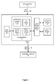
Figure 1 is a block diagram of an example device for converting a signal. -
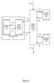
Figure 2 is a block diagram of an example device for converting a signal. -
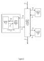
Figure 3 is a block diagram of an example device for converting a signal. -
Figure 4 is a block diagram of an example of components of a device for converting a signal. -
Figure 5 is a flow diagram of an example method for converting a signal using a device for performing signal conversion. -
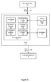
Figure 6 is a block diagram of an example of components of a device for converting a signal. -
Figure 7 is a block diagram of an example of components of a device for converting a signal. -
Figure 8 is a flow diagram of an example method for converting a signal using a device for performing signal conversion. -
Figure 9 is a block diagram of an example system for converting a signal. -
Figure 10 is a block diagram of an example system for converting a signal. -
Figure 11 is a block diagram of an example system for converting a signal. - Information and data ("data") may be stored in and carried by signals or other transmissions ("signals") to or from one or more devices. Such signals may be sent or transmitted to, or received by, a device continuously, at periodic intervals, when an event triggers a transmission, or at various other times. A transmitting or receiving device may desire or need to convert a signal or data about a signal from one domain to another domain prior to or after analyzing or processing the signal. For example, a device may receive a time domain audio signal, upon which the device may wish to perform frequency domain processing, such as noise reduction, de-reverberation processing or algorithms, QuantumLogic™, or other surround sound algorithms. Frequency domain processing may be increasing in prevalence in some processors. As such, the device may need to convert the received time domain audio signal into the frequency domain in order to perform the desired frequency domain processing. As another example, a device may access or receive frequency domain data about a signal, upon which the device may desire to convert the frequency domain data into the time domain in order to perform time domain processing. As another example, a device may receive and process frequency domain data about a signal, after which the device may need to convert the frequency domain data into a time domain signal, such as where it is desirable that the device transmit the signal in a certain format.
-
Figure 1 illustrates an environment where one or more signals may be received by, processed using, or transmitted from adevice 100. Thedevice 100 may include one or more hardware abstraction layers, above a transform layer, that may be used for transforming a signal or data about a signal back and forth between the time and frequency domains in real time or near real time. - The
device 100 may receive one ormore input signals 105, such as from one or moreinput signal sources 107. Theinput signal 105 may be or represent one or more signal types or formats, and/or may exist or be represented in one or more domains. For example, theinput signal 105 may be an audio signal, a video signal, an information-carrying signal, or various other signals or combinations of signals. The receivedinput signal 105 may, for example, be or be represented in a time domain or a frequency domain. - The
input signal 105 may be generated, sent and/or transmitted from one or moreinput signal sources 107 to thedevice 100. Theinput signal source 107 may, for example, be a microphone or soundboard transmitting an audio signal, a media player such as a DVD player transmitting an audio, video, or audio/video signal, a processor transmitting various types of information or media signals, or any other source or device that may generate, send, or transmit a signal to thedevice 100. - The
device 100 may be used to perform one or multiple signal conversions, such as multiple Fast Fourier Transforms ("FFTs") and inverse FFTs, on continuously received signals in real time or near real-time. Thedevice 100 may perform these signal conversions without utilizing fast internal memory or hardware accelerator blocks on aprocessing module 110. Instead, signal conversions may be performed through the use of remote medium-speed memory 140 and domain conversion hardware, such as an overlap-and-add short time Fast Fourier Transform ("OLA/STFFT")hardware 150 or an overlap-and-add inverse short time Fast Fourier Transform ("OLA/iSTFFT")hardware 160, as discussed later. - The
device 100 may also or alternatively extract data from the signal, and/or may process, analyze, apply algorithms to, or otherwise manipulate the received signal and/or data from the signal, such as through or with aprocessing module 110 as discussed later. For example, thedevice 100 may apply one or more surround sound, noise reduction, or de-reverberation algorithms to the received data about a signal. Various other processes may be performed. After processing, the device may also or alternatively perform one or more signal or data conversions on the processed or manipulated signals or data, such as using the remote medium-speed memory 140, OLA/STFFT hardware 150, and OLA/iSTFFT hardware 160. - After converting and/or processing the signal or data from the signal, the
device 100 may output anoutput signal 195. Theoutput signal 195 may be or represent one or more signal types or formats. For example, theoutput signal 195 may be an audio signal, a video signal, an information-carrying signal, or various other signals. Theoutput signal 195 may exist or be represented in one or more domains. For example, theoutput signal 195 may, for example, be or be represented in a time domain or a frequency domain. Theoutput signal 195 may have similar or different properties from theinput signal 105. For example, theinput signal 105 and theoutput signal 195 may both be represented in the same domain (such as where both are time domain signals or both are frequency domain signals), or theinput signal 105 may be represented in a first domain while theoutput signal 195 may be represented in a second, different domain. Other variations are possible. Theoutput signal 195 may be sent from thedevice 100 to one or moreoutput signal destinations 190.Output signal destinations 190 may, for example, be speakers configured to receive surround sound audio output signals 195. Otheroutput signal destinations 190 may, for example, include one or more monitors, processors, mixing boards, amplifiers, or any device or component configured to receive a signal. - The
device 100 may include aprocessing module 110. Theprocessing module 110 may be or represent one or more digital signal processor ("DSP"), analog processor or chip, processing chip, other physical processor, field programmable gate array ("FPGA"), and/or other integrated circuit. Theprocessing module 110 may include one or more of acomputing module 115, memory such asfast memory 118, and one or moreremote memory interfaces processing module 110 may be external or included in one or more separate integrated circuits or chips that form theprocessing module 110. In other systems, theprocessing module 110 may also or alternatively directly includeslow memory 120 and/or medium-speed memory 140 within theprocessing module 110. Theprocessing module 110, or one or more components within theprocessing module 110, may communicate internally or with other components within theprocessing module 110 in various ways, such as by or through wired or wireless communication links, by or using a communication bus interconnecting one or more components of theprocessing module 110, or through various other communication links or lines. Additional or fewer components may be possible. - The
computing module 115 of theprocessing module 110 may, for example, represent hardware or hardware accelerator blocks that may be used for performing one or more processes, computations, calculations, algorithms, or other manipulations or for running software, code, or other logic. For example, thecomputing module 115 may perform core logic functions, such as surround sound, noise reduction, or de-reverberation algorithms, on frequency domain audio signals or data. As another example, thecomputing module 115 may be used to combine, mix, synthesize, filter, up-sample, down-sample, de-noise, or otherwise process a signal or data received by thedevice 100. Various other examples are possible. - The
processing module 110 may include or access various types of memory. For example, theprocessing module 110 may include internalfast memory 118. Internalfast memory 118 may be or include dynamic random-access memory ("DRAM"), content addressable memory, cache memory, internal random-access memory ("RAM"), and/or various other types of internal fast memory.Fast memory 118, such as internal RAM, may have an asynchronous interface, which may allow thefast memory 118 to respond as quickly as possible to changes in control inputs. - The
processing module 110 may additionally or alternatively include one or moreremote memory interfaces remote memory interface 129 may be used to connect or communicate with a remote slow memory, such asslow memory 120. Theremote memory interface 129 may, for example, be or include an asynchronous random-access memory ("RAM") bus that may be used to communicate with theslow memory 120.Slow memory 120 may, for example, be or include synchronous dynamic random-access memory ("SDRAM") memory, double data rate synchronous dynamic random access memory ("DDR SDRAM," "DDR," or "DDR memory"), or various other types of slow memory.Slow memory 120 may, for example, be accessed using a direct-memory access ("DMA") controller or other device.Slow memory 120 may be very slow compared to thefast memory 118.Slow memory 120 may be used for or during processing or computations that are not time-sensitive or dependent. In some systems,slow memory 120 may be so slow that it may not be practical or possible to use theslow memory 120 with real-time or near real-time calculations, such as real-time or near real-time FFTs or iFFTs. Theremote memory interface 129 may be or provide an interface between theprocessing module 110 and theslow memory 120, allowing theprocessing module 110 to access and use data, information, code, or logic stored within theslow memory 120. Whileslow memory 120 is shown as being included within thedevice 100 but separate from theprocessing module 110, in some systems, theslow memory 120 may be completely separate from thedevice 100, or may be included within theprocessing module 110. Various other configurations are possible. - The
remote memory interface 130 may be used to connect or communicate with remote medium-speed memory 140. For example, theremote memory interface 130 may be similar to or resemble theremote memory interface 129 and may include an asynchronous random-access memory ("RAM") bus that may be used to communicate with the remote medium-speed memory 140. Remote medium-speed memory 140 may be or include, for example, static random-access memory ("SRAM"), or other memory which may be separate from and accessible to theprocessing module 110. Remote medium-speed memory 140 such as SRAM may be slower thanfast memory 118 like internal RAM, but may be considerably faster than theslow memory 120 like DDR or SDRAM memory. Theremote memory interface 130 may be or provide an interface between theprocessing module 110 and the remote medium-speed memory 140, allowing theprocessing module 110 to access and use data, information, code, or logic stored within the remote medium-speed memory 140. While remote medium-speed memory 140 is shown as being included within thedevice 100 but separate from theprocessing module 110, in some systems, the medium-speed memory 140 may be completely separate from thedevice 100, or may be included within theprocessing module 110. Various other configurations are possible. - Part or all of the memory on or accessible to the
processing module 110, such as thefast memory 118, theslow memory 120, and the remote medium-speed memory 140, may be used to store one or more of data, information, code, or logic. Various hardware components or other computing modules, such as thecomputing module 115, may access code or logic stored in memory on or accessible to theprocessing module 110 which may include instructions for performing one or more processes, computations, calculations, or algorithms. The hardware and computing modules may also or alternatively use signals or data stored in memory as inputs upon which to perform one or more processes, computations, calculations, or algorithms. The hardware and computing modules may store data or other information in memory on or accessible to theprocessing module 110 before, during, or after processing, calculating, or performing other manipulations various signals or data. For example, thecomputing module 115 may store data related to partial calculations or data related to intermediate steps of a computation or process in memory, which thecomputing module 115 may later retrieve and use in subsequent processing or algorithmic steps. - When performing complex, fast, real-time, near real-time, highly desirable, or core processes, algorithms, computations, or calculations, such as various surround sound, noise reduction, or de-reverberation algorithms, it may be useful and advantageous to utilize the
fast memory 118 on theprocessing module 110 to store one or more of the data, information, code, and logic necessary to perform processes, as well as thecomputing module 115 to perform the desired processes. The internalfast memory 118 may represent the most efficient cost-effective manner of performing these processes. Thefast memory 118 may store frequency domain data or signals upon which theprocessing module 110 may perform surround sound, noise reduction, or de-reverberation algorithms, as well as the code or logic storing the instructions for performing the surround sound, noise reduction, or de-reverberation algorithms. Thecomputing module 115 may additionally or alternatively use thefast memory 118 to store intermediate data or information resulting from computations or calculations associated with surround sound, noise reduction, or de-reverberation processes. Various other types of processes and examples are possible. - However, some
processing modules 110 or computingmodules 115 may not be able to efficiently perform signal conversions in addition to other core logic or processes that thechip 110 may be running. For example, in some systems, while theprocessing module 110 may include an FFT hardware block or hardware accelerator, these FFT hardware blocks are generally unable or unsuitable for performing multiple FFTs or iFFTs on continuously received signals in real time or near real time. As such, these FFT hardware blocks may not be useful with thecomputing module 115 in continuously converting and processing signals received in real-time. Even if the FFT hardware blocks were technically capable of performing multiple FFTs and iFFTs on data received, the frequency domain processing often requires large amounts offast memory 118 and/ormedium speed memory 140 for data storage. However, the internalfast memory 118 may be expensive and represent valuable memory useful for processing performed by theprocessing module 110. Additionally, an amount of internalfast memory 118 available for processing may be very limited. Using any amount of internalfast memory 118 for the signal conversion may slow all other core processes, making theprocessing module 110 inadequate for performing real-time signal conversion and processing. - Accordingly, while the
fast memory 118,computing module 115, and other components of theprocessing module 110 may be used to perform various core logic functions, thedevice 100 may utilize the remote medium-speed memory 140, as well as one or more OLA/STFFT hardware 150 and OLA/iSTFFT hardware 160 in communication with the remote medium-speed memory 140, for the performance of one or more signal conversions. In some systems, handshaking between these components may be implemented in various ways including on chip specific of general purpose registers. - The OLA/
STFFT hardware 150 may be or include one or more of an application specific integrated circuits, field programmable gate arrays, analog circuits, a general processor, digital signal processor, servers, networks, digital circuits, combinations thereof, or other now known or later developed devices for receiving and converting a signal or data about a signal from a first domain to a second domain, such as by or through one or more domain transformations. As a specific example, the OLA/STFFT hardware 150 may be configured or operable to convert a signal or data from a time domain to a frequency domain, such as by or through the application of one or more FFT algorithms. The OLA/STFFT hardware 150 may implement a software program, such as code generated manually (i.e., programmed). - The OLA/
iSTFFT hardware 160 may be or include one or more of an application specific integrated circuits, field programmable gate arrays, analog circuits, a general processor, digital signal processor, servers, networks, digital circuits, combinations thereof, or other now known or later developed devices for receiving and converting a signal or data about a signal from a second domain to a first domain, such as by or through one or more domain transformations. As a specific example, the OLA/iSTFFT hardware 160 may be configured or operable to convert a signal or data from a frequency domain to a time domain, such as by or through the application of one or more iFFT algorithms. The OLA/iSTFFT hardware 160 may implement a software program, such as code generated manually (i.e., programmed). While the OLA/STFFT hardware 150 and/or the OLA/iSTFFT hardware 160 may be described with reference to converting a signal or data to or from a frequency domain or a time domain using various Fourier transforms, either or both the OLA/STFFT hardware 150 and the OLA/iSTFFT hardware 160 may be configured or operable to use or apply one or more other transformation functions or algorithms to transform a signal or data to or from various domains, such as a time domain, frequency domain, a warped frequency domain, a wavelet domain, a filter bank domain, or various other domains. While the OLA/STFFT hardware 150 and the OLA/iSTFFT hardware 160 are shown inFigure 1 as separate hardware components, in some systems, the OLA/STFFT hardware 150 and the OLA/iSTFFT hardware 160 may be the same, or part of the same, component, and may be separate from theprocessing module 110. Other variations or examples are possible. - The remote medium-
speed memory 140 may be used to store data needed or required for performance of an FFT or an iFFT. The remote medium-speed memory 140 may be connected with or communicate with one or more OLA/STFFT hardware 150 and OLA/iSTFFT hardware 160, which may perform the FFT or iFFT remotely, separately, and distinctly from theprocessing module 110, as discussed below. Each of the OLA/STFFT hardware 150 and OLA/iSTFFT hardware 160 may be or represent a hardware abstraction layer in addition to hardware layers of theprocessing module 110. While one remote medium-speed memory 140 is shown, in some systems, each of the domain conversion hardware components may access and use separate remote medium-speed memories. - The use of the remote medium-
speed memory 140 and one or more of the OLA/STFFT hardware 150 and OLA/iSTFFT hardware 160 for performing signal conversions, as discussed below, may free the valuable computing power of thecomputing module 115 and thefast memory 118 of theprocessing module 110 to perform the most complex and desirable processing functions without being slowed or compromised by storing or processing data, information, code, and logic necessary to perform the signal conversions. The use of these components for performing signal conversion without using the resources of theprocessing module 110 may represent a reasonable tradeoff between price and memory access speeds, as the remote medium-speed memory 140 may be cheaper than thefast memory 118. The use of remote medium-speed memory 140 may allow theprocessing modules 110 to be made smaller and with lessfast memory 118 than if thefast memory 118 were needed for performing signal conversions. While frequently described with respect to converting a time domain audio signal into a frequency domain data for processing, the signal converting components of thedevice 100 may be used in any device or system where a signal is received and is desired to be converted to a different domain prior to or after processing of the signal. -
Figures 2 and3 show examples of how theprocessing module 110, the remote medium-speed memory 140, and domain conversion hardware such as the OLA/STFFT hardware 150 and/or the OLA/iSTFFT hardware 160, may communicate in order to may perform one or more signal conversions and processes for thedevice 100. - The configuration in
Figure 2 may be used where thecomputing module 115 of theprocessing module 110 may desire to receive a frequency domain signal or data for processing. A timedomain input signal 200 may be received by the remote medium-speed memory 140. The timedomain input signal 200 may be similar to or the same as theinput signal 105. While the timedomain input signal 200 is shown as being received directly by the remote medium-speed memory 140, in some other systems, the timedomain input signal 200 may first be received by theprocessing module 110, a transceiver, an interface, or another component, after which the timedomain input signal 200 may be sent to or received by the remote medium-speed memory 140. - The time
domain input signal 200, data from or about the timedomain input signal 200, or samples from the timedomain input signal 200, may be stored in the remote medium-speed memory 140 as timedomain input data 202. Storage of the timedomain input data 202 in the remote medium-speed memory 140 may occur continuously as theinput signal 200 is received, periodically, at intervals, when triggered, or at various other times. - The stored time domain
input signal data 202 may be sent to, or accessed by the OLA/STFFT hardware 150. The OLA/STFFT hardware 150 may receive or access the time domaininput signal data 202 continuously, periodically, when triggered, or at various intervals, such as when a buffer in the remote medium-speed memory 140 is full or nearly full of samples or data about the timedomain input signal 200. In other systems, the timedomain input signal 200 may be sent directly to the OLA/STFFT hardware 150 without storing any timedomain input data 202 in the remote medium-speed memory 140. - Once the OLA/
STFFT hardware 150 has received an amount of time domaininput signal data 202, such as a predetermined number of input signal samples, the OLA/STFFT hardware 150 may perform a signal conversion on the time domaininput signal data 202 received. In some systems, one or more registers may be incorporated and/or used for handshaking. - The OLA/
STFFT hardware 150 may convert the signal or data from a time domain into a frequency domain in various ways, such as by applying a Fourier Transform to a time domain signal or data. The Fourier Transform may decompose a sequence of values into components of different frequencies, thereby converting the time domain signal into a frequency domain signal. A Fast Fourier Transform ("FFT") may be an efficient way of converting the time domain signal to a frequency domain signal, as the FFT applies a Fourier Transform to a discrete set of samples or representative values of the time domain signal, reducing computational steps with minimal accuracy sacrifices. Various FFT algorithms, such as a Cooley-Tukey FFT algorithm, Prime-factor FFT algorithms, Split-radix FFT algorithms, Bruun's FFT algorithm, Radar's FFT algorithm, Bluestein's FFT algorithm, or various other FFT algorithms, may be implemented or used by a device to convert a time domain signal into a frequency domain signal. The result of the signal conversion performed by the OLA/STFFT hardware 150 may be a frequency domain input signal or frequency domain data about the timedomain input signal 200, which may be referred to as the OLA/STFFT output data 204. While the systems and methods may describe uses with various FFT and inverse FFT transforms, it should be appreciated that the OLA/STFFT hardware 150 and/or the OLA/iSTFFT hardware 160 may be configured and or used to perform other non-FFT transforms, such as wavelets, discrete cosine transforms, and various other transforms. - The
processing module 110 may receive or access the frequency domain OLA/STFFT output data 204 as a frequency domain input signal or frequency domain input data, referred to as frequencydomain input data 206. The frequencydomain input data 206 may be, or may be the same as, the frequency domain OLA/STFFT output data 204. One or more of the frequency domain OLA/STFFT output data 204 or frequencydomain input signal 206 may be represented in a domain or format that may be used by theprocessing module 110 of thedevice 100 for processing or other algorithms. - In some systems, the frequency domain OLA/
STFFT output data 204 may first be sent to, or accessed by, the remote medium-speed memory 140, after which theprocessing module 110 may receive the frequencydomain input data 206. In these systems, the remote medium-speed memory 140 may or may not store the frequency domain OLA/STFFT output data 204. In other systems, the frequency domain OLA/STFFT 204 may be sent directly to, or accessed directly by, theprocessing module 110. - The
processing module 110 may receive or access the frequencydomain input signal 206 through or using theremote memory interface 130 or with or through the use of a DMA controller. Theprocessing module 110 may receive or access the frequencydomain input signal 206 continuously, periodically, when triggered, or at various intervals, such as after each FFT is performed by the OLA/STFFT hardware 150. In some systems, the frequencydomain input signal 206 may be stored and transferred to theprocessing module 110 over or using a memory bus where memory bandwidth utilization may be maximized, such as by arranging the data in a contiguous manner. Other variations are possible. - The
remote memory interface 130 may send or transmit the received frequencydomain input data 206 to thecomputing module 115 of thechip 110 as theprocessing input data 208. The processinginput data 208 may be the same as, represent, or be similar to the frequencydomain input data 206. - The processing
input data 208 may be in a domain or format that may be used by or necessary for processing by thecomputing module 115. For example, the processinginput data 208 may be frequency domain data where thecomputing module 115 desires or requires frequency domain signals or data in order to perform various processes, algorithms, or other tasks. - The
computing module 115 may perform or apply one or more processes, algorithms, logic, code, software, or other analysis on theprocessing input data 208. For example, thecomputing module 115 may apply various surround sound algorithms on theprocessing input data 208. Thecomputing module 115 may or may not use or access other memory, such as fastinternal memory 118 orslow memory 120, before, during, or after the processing of theprocessing input data 208. For example, code or logic with instructions for the processing performed by thecomputing module 115 may be stored in thefast memory 118, and accessed by thecomputing module 115 before or during the operation of any processing or calculations performed by thecomputing module 115 on theprocessing input data 208. - A result of the processing performed by the
computing module 115 may be frequency domainprocessing output data 210. The processed frequencydomain output data 210 may then be sent to or accessed by theremote memory interface 130 of theprocessing module 110. - The remote medium-
speed memory 140 may receive or access a frequencydomain output signal 212 from theremote memory interface 130. The frequencydomain output signal 212 may be the same as, represent, or be similar to the frequency domainprocessing output data 210. - While the
processing input data 208 is shown as being sent directly to thecomputing module 115, in some systems, the frequencydomain input signal 206 may be stored in memory on or accessible to theprocessing module 110, such as internalfast memory 118 orslow memory 120, prior to, during, or after being received or accessed by thecomputing module 115. Additionally or alternatively, while theprocessing output data 210 is shown as being sent directly to theremote memory interface 130, in some systems, theprocessing output data 210 may be stored in memory on or accessible to theprocessing module 110, such as internalfast memory 118 orslow memory 120, prior to, during, or after being sent to or accessed by theremote memory interface 130. - The remote medium-
speed memory 140 may receive or otherwise access and/or store the frequency domain output signal or data about the frequency domain output signal, referred to as frequency domainoutput signal data 214. Storage of the frequency domainoutput signal data 214 in the remote medium-speed memory 140 may occur continuously, periodically, when triggered, at intervals, such as at every interval where thecomputing module 115 has completed processing theprocessing input data 208 and has outputted theprocessing output data 210, or at various other times. - The stored frequency domain
output signal data 214 may be sent to, or accessed by the OLA/iSTFFT hardware 160, which may be referred to as an inverse domain conversion hardware. The OLA/iSTFFT hardware 160 may receive or access the frequency domainoutput signal data 214 continuously, periodically, when triggered, or at various intervals, such as when a buffer in the remote medium-speed memory 140 is full or nearly full of samples or data about the frequencydomain output signal 212 or at each time interval that the OLA/STFFT hardware 150 receives time domaininput signal data 202 from the remote medium-speed memory 140. In other systems, the frequencydomain output signal 212 may be sent directly to the OLA/iSTFFT hardware 160 without storing any frequency domainoutput signal data 214 in the remote medium-speed memory 140. - The OLA/
iSTFFT hardware 160 may perform a signal conversion on the frequency domainoutput signal data 214 received. The OLA/iSTFFT hardware 160 may convert the signal or data from a frequency domain into a time domain in various ways as well. For example, the OLA/iSTFFT hardware 160 may apply an inverse Fourier Transform to the frequency domain signal or data, such as an Inverse Fast Fourier Transform ("iFFT" or "inverse FFT"), or various other non-FFT transformations. Inverse FFT's may operate to recover a time domain signal by constructing the time domain signal from the frequency domain signal. The result of the signal conversion performed by the OLA/iSTFFT hardware 160 may be a time domain output signal or time domain data about the frequencydomain output signal 212, which may be referred to as the OLA/iSTFFT output data 216. - The
processing module 110 may receive or access the time domain OLA/iSTFFT output data 216 as a time domain output signal or time domain output data, referred to as timedomain output signal 218. The timedomain output signal 218 may be, or may be the same as, the time domain OLA/iSTFFT output data 216. One or more of the time domain OLA/iSTFFT output data 216 or timedomain output signal 218 may be represented in a domain or format that may be useful tooutput signal destinations 190. The timedomain output signal 218 may be similar to or the same as the output signal 185. - In some systems, the time domain OLA/
iSTFFT output data 216 may be sent to, or accessible to, the remote medium-speed memory 140, after which theoutput signal destinations 190 may receive the timedomain output signal 218. In these systems, the remote medium-speed memory 140 may or may not store the time domain OLA/iSTFFT output data 216. In other systems, the time domain OLA/iSTFFT output data 216 may be sent directly to, or accessed directly by, theoutput signal destinations 190. In some systems, theoutput data 216 may be sent to theoutput signal destinations 190 through thedevice 100, through an interface on the remote medium-speed memory 140, or in various other ways. - While
Figure 2 shows a timedomain input signal 200 and a timedomain output signal 218, it should be appreciated that the system could be modified depending on the type ofinput signal 200 received and/or the type of output signal desired. For example, where theinput signal 200 is a frequency domain signal, the system may eliminate the use of the OLA/STFFT hardware 150. In this example, theinput signal 200 may be sent as a frequencydomain input signal 206 to theprocessing module 110 for processing. As another example, where a frequencydomain output signal 212 is desired by one or moreoutput signal destinations 190, thedevice 100 may eliminate the use of the OLA/iSTFFT hardware 160. In this example, theoutput signal 218 may be or reflect the frequencydomain output signal 210 from thecomputing module 115. Various other examples are possible. - The system in
Figure 2 may be utilized to provide frequency domain signals to acomputing module 115.Figure 3 illustrates an opposite configuration, where thecomputing module 115 of theprocessing module 110 may desire to receive a time domain signal or data for processing. - A frequency
domain input signal 300 may be received by the remote medium-speed memory 140. The frequencydomain input signal 300 may be similar to or the same as theinput signal 105. While the frequencydomain input signal 300 is shown as being received directly by the remote medium-speed memory 140, in some other systems, the frequencydomain input signal 300 may first be received by theprocessing module 110, a transceiver, an interface, or another component, after which the frequencydomain input signal 300 may be sent to or received by the remote medium-speed memory 140. - The frequency
domain input signal 300, data from or about the frequencydomain input signal 300, or samples from the frequencydomain input signal 300, may be stored in the remote medium-speed memory 140 as frequencydomain input data 302. Storage of the frequencydomain input data 302 in the remote medium-speed memory 140 may occur continuously as theinput signal 300 is received, periodically, at intervals, when triggered, or at various other times. - The stored frequency
domain input data 302 may be sent to, or accessed by the OLA/iSTFFT hardware 160. The OLA/iSTFFT hardware 160 may receive or access the frequencydomain input data 302 continuously, periodically, when triggered, or at various intervals, such as when a buffer in the remote medium-speed memory 140 is full or nearly full of data about the frequencydomain input signal 300. In other systems, the frequencydomain input signal 300 may be sent directly to the OLA/iSTFFT hardware 160 without storing any frequencydomain input data 302 in the remote medium-speed memory 140. - Once the OLA/
iSTFFT hardware 160 has received an amount of frequencydomain input data 302, the OLA/iSTFFT hardware 160 may perform a signal conversion on the frequencydomain input data 302 received. For example, the OLA/iSTFFT hardware 160 may perform an iFFT on frequency domain data received to convert the input signal from the frequency domain into the time domain. The result of the signal conversion performed by the OLA/iSTFFT hardware 160 may be a time domain input signal or time domain data about the frequencydomain input signal 300, which may be referred to as the OLA/iSTFFT output data 304 and may be configured to be processed by thecomputing module 115. - The
processing module 110 may receive or access the time domain OLA/iSTFFT output data 304 as a time domain input signal or time domain input data, referred to as timedomain input data 306. The timedomain input data 306 may be, or may be the same as, the time domain OLA/iSTFFT output data 304. One or more of the time domain OLA/iSTFFT output data 304 or timedomain input data 306 may be represented in a domain or format that may be used by theprocessing module 110 of thedevice 100 for processing or other algorithms. - In some systems, the time domain OLA/
iSTFFT output data 304 may first be sent to, or accessible to, the remote medium-speed memory 140, after which theprocessing module 110 may receive the timedomain input data 306. In these systems, the remote medium-speed memory 140 may or may not store the time domain OLA/iSTFFT output data 304. In other systems, the time domain OLA/iSTFFT 304 may be sent directly to, or accessed directly by, theprocessing module 110. Though it may occur at a different point in the conversion or processing of a signal, the inputs, operation, and outputs from the OLA/iSTFFT hardware 160 inFigure 3 may be similar to or the same as the inputs, operation, and outputs from the OLA/iSTFFT hardware 160 inFigure 2 . - The
processing module 110 may receive or access the timedomain input data 306 through or using theremote memory interface 130. Theprocessing module 110 may receive or access the timedomain input data 306 continuously, periodically, when triggered, or at various intervals, such as after each iFFT is performed by the OLA/iSTFFT hardware 160. - The
remote memory interface 130 may send or transmit the received timedomain input data 306 to thecomputing module 115 of thechip 110 as theprocessing input data 308. The processinginput data 308 may be the same as, represent, or be similar to the timedomain input data 306. - The processing
input data 308 may be in a domain or format that may be used by or necessary for processing by thecomputing module 115. For example, the processinginput data 308 may be time domain data where thecomputing module 115 desires or requires time domain signals or data in order to perform various processes, algorithms, or other tasks. - The
computing module 115 may perform or apply one or more processes, algorithms, logic, code, software, or other analysis on theprocessing input data 308. Thecomputing module 115 may or may not use or access other memory, such as fastinternal memory 118 orslow memory 120, before, during, or after the processing of theprocessing input data 308. For example, code or logic with instructions for the processing performed by thecomputing module 115 may be stored in thefast memory 118, and accessed by thecomputing module 115 before or during the operation of any processing or calculations performed by thecomputing module 115 on theprocessing input data 308. - A result of the processing performed by the
computing module 115 may be time domainprocessing output data 310. The processed time domainprocessing output data 310 may then be sent to or accessed by theremote memory interface 130 of theprocessing module 110. - The remote medium-
speed memory 140 may receive or access a timedomain output signal 312 from theremote memory interface 130. The timedomain output signal 312 may be the same as, represent, or be similar to the time domainprocessing output data 310. - While the
processing input data 308 is shown as being sent directly to thecomputing module 115, in some systems, the timedomain input signal 306 or theprocessing input data 308 may be stored in memory on or accessible to theprocessing module 110, such as internalfast memory 118 orslow memory 120, prior to, during, or after being received or accessed by thecomputing module 115. Additionally or alternatively, while theprocessing output data 310 is shown as being sent directly to theremote memory interface 130, in some systems, theprocessing output data 310 may be stored in memory on or accessible to theprocessing module 110, such as internalfast memory 118 orslow memory 120, prior to, during, or after being sent to or accessed by theremote memory interface 130. - The remote medium-
speed memory 140 may access and/or store the time domain output signal or data about the time domain output signal, referred to as time domainoutput signal data 314. Storage of the time domainoutput signal data 314 in the remote medium-speed memory 140 may occur continuously, periodically, when triggered, at intervals, such as at every interval where thecomputing module 115 has completed processing theprocessing input data 308 and has outputted theprocessing output data 310, or at various other times. - The stored time domain
output signal data 314 may be sent to, or accessed by the OLA/STFFT hardware 150. The OLA/STFFT hardware 150 may receive or access the time domainoutput signal data 314 continuously, periodically, when triggered, or at various intervals, such as when a buffer in the remote medium-speed memory 140 is full or nearly full of samples or data about the timedomain output signal 312 or at each time interval that the OLA/iSTFFT hardware 160 receives frequency domaininput signal data 302 from the remote medium-speed memory 140. In other systems, the timedomain output signal 312 may be sent directly to the OLA/STFFT hardware 150 without storing any time domainoutput signal data 314 in the remote medium-speed memory 140. - The OLA/
STFFT hardware 150 may perform a signal conversion on the time domainoutput signal data 314 received. For example, the OLA/STFFT hardware 150 may perform a FFT on time domain output signal samples received to convert the output signal from the time domain into the frequency domain. The result of the signal conversion performed by the OLA/STFFT hardware 150 may be a frequency domain output signal or frequency domain data about the timedomain output signal 312, which may be referred to as the OLA/STFFT output data 316. Though it may occur at a different point in the conversion or processing of a signal, the inputs, operation, and outputs from the OLA/STFFT hardware 150 inFigure 3 may be similar to or the same as the inputs, operation, and outputs from the OLA/STFFT hardware 150 inFigure 2 . - The
processing module 110 may receive or access the frequency domain OLA/STFFT output data 316 as a frequency domain output signal or frequency domain output data, referred to as frequencydomain output signal 218. The frequencydomain output signal 218 may be, or may be the same as, the frequency domain OLA/STFFT output data 316. One or more of the frequency domain OLA/STFFT output data 316 or frequencydomain output signal 318 may be represented in a domain or format that may be useful tooutput signal destinations 190. The frequencydomain output signal 318 may be similar to or the same as theoutput signal 195. - In some systems, the frequency domain OLA/
STFFT output data 316 may be sent to, or otherwise accessible to, the remote medium-speed memory 140, after which theoutput signal destinations 190 may receive the frequencydomain output signal 318. In these systems, the remote medium-speed memory 140 may or may not store the frequency domain OLA/STFFT output data 316. In other systems, the frequency domain OLA/STFFT output data 316 may be sent directly to, or accessed directly by, theoutput signal destinations 190. - While
Figure 3 shows a frequencydomain input signal 300 and a frequencydomain output signal 318, it should be appreciated that the system could be modified depending on the type ofinput signal 300 received and/or the type of output signal desired. For example, where theinput signal 300 is a time domain signal, the system may eliminate the use of the OLA/iSTFFT hardware 160. In this example, theinput signal 300 may be sent as a timedomain input signal 306 to theprocessing module 110 for processing. As another example, where a timedomain output signal 318 is desired by one or moreoutput signal destinations 190, thedevice 100 may eliminate the use of the OLA/STFFT hardware 150. In this example, theoutput signal 318 may be or reflect the timedomain output signal 310 from thecomputing module 115. Various other examples are possible. -
Figure 4 is a block diagram of an example remote medium-speed memory 140 and OLA/STFFT hardware 150, and illustrates how the remote medium-speed memory 140 may interact and operate with the OLA/STFFT hardware 150 to convert a signal from the time domain to the frequency domain remotely and distinctly from theprocessing module 110 of thedevice 100. - The remote medium-
speed memory 140 may receive a signal or data about a signal, such assignal input 405. Thesignal input 405 may be received continuously, periodically, at one or more intervals, or at various times. Thesignal input 405 may be a time domain signal or data about a time domain signal, and may be the same as or similar to theinput signal 105, the timedomain input signal 200, or the timedomain output signal 312. - The remote medium-
speed memory 140 may include abuffer 410, which may store thesignal input 405. For example, the remote medium-speed memory 140 may continuously or periodically receive a time domain signal sample, and may store each received time domain signal sample in thebuffer 410. Where thesignal input 405 is a time domain signal, an additional component may be provided which may receive the time domain signal and generate or gather data or samples from the time domain signal, which are then stored in thebuffer 410 of the remote medium-speed memory 140. - The
signal input 405 stored in thebuffer 410 may be sent to or accessed by the OLA/STFFT hardware 150. Thesignal input 405 may be received by the OLA/STFFT hardware 150 continuously, periodically, when triggered, or at various intervals or other times. For example, when enough signal input data has been stored in thebuffer 410 to perform a signal conversion, thebuffer 410 may send the storedsignal input 405 to the OLA/STFFT hardware 150 as bufferedinput data 412 for performance of a FFT on the bufferedinput data 412. As an example, where the OLA/STFFT hardware 150 is configured to perform a 1024 point FFT, thebuffer 410 may store receivedsignal input 405 in the form of time domain signal samples until 1024 samples have been received and stored in thebuffer 410. Once 1024 samples have been stored in thebuffer 410, the remote medium-speed memory 140 may send, or the OLA/STFFT hardware 150 may otherwise access, the samples as bufferedinput data 412. Once the bufferedinput data 412 have been sent to or accessed by the OLA/STFFT hardware 150, the time domain signal samples stored in thebuffer 410 may be shifted, partially shifted, wrapped, partially wrapped, cleared, partially cleared, removed, or otherwise deleted or altered in various ways, and thebuffer 410 may again begin storing new time domain signal samples as they are received by the remote medium-speed memory 140. - The remote medium-
speed memory 140 may also or alternatively receive window input data such as awindow input 415.Window input 415 may include code, logic, instructions, information or data regarding a window function to be performed on the bufferedinput data 412 by the OLA/STFFT hardware 150. A window function may be a mathematical function that is zero-valued outside of a chosen interval. When a signal or data, such as the bufferedinput data 412, is multiplied by the window function, the product is also zero-valued outside the interval, and all that is left is the part where they overlap. For instance, a function that is constant inside the interval and zero elsewhere is called a rectangular window, which describes the shape of its graphical representation. Various other window functions are possible, such as a triangular window, a cosine window, a flat top window, an exponential window, a Gaussian window, a Hann window, a Bartlett-Hann window, a Hamming window, a Tukey window, a Lanczos window, a Blackman window, a Blackman-Harris window, a Blackman-Nuttall window, a Kaiser window, a Bessel window, a Dolph-Chebyshev window, a Nuttall window, a Hann-Poisson window, a Rife-Vincent window, a Slepian window, square roots of any of these windows, or various other windows or combinations of windows. A window function may be applied to a set of data before performing an FFT to reduce or eliminate artifacts from the FFT or to reduce the abruptness of the FFT at each transition. - In some systems, such as systems where a signal may be first converted or transformed from a first domain to a second domain using an OLA/
STFFT hardware 150, then processed, then reconverted or retransformed back to the first domain using an OLA/iSTFFT hardware 160, the window functions of the OLA/STFFT hardware 150 and OLA/iSTFFT hardware 160 (discussed below) may be determined, selected, chosen, or implemented as complementary window functions. For example, in some systems, the OLA/STFFT hardware 150 may include a first window function, which may be referred to as an analysis window, and the OLA/iSTFFT hardware 160 may include a second window function, which may be referred to as a reconstruction window or a synthesis window. The analysis window and the synthesis window may be configured such that the combined effect of the two window functions, in the absence of any intermediary processing, is equal to 1 or unity, and/or provides perfect reconstruction. Though the analysis window is described with reference to the OLA/STFFT hardware 150 and the synthesis window is described with reference to the OLA/iSTFFT hardware 160, in other systems, these may be reversed. As one specific example, the analysis window (or a window of the OLA/STFFT hardware 150) and the synthesis window (or a window of the OLA/iSTFFT hardware 160) may be a square root of a Hamming window or a Hann window. Various other examples and variations are possible. -
Window input 415 may, for example, be provided to the remote medium-speed memory 140 by thecomputing module 115 or another component of theprocessing module 110 to control the window function to be applied during the performance of an FFT by the OLA/STFFT hardware 150. In other systems, thewindow input 415 may be provided to the remote medium-speed memory 140 by one or more other devices, software, logic, hardware that may be configured or operable to supply this information the remote medium-speed memory 140 and/or determine and designate an appropriate window function to be performed. - The
window input 415 received by the remote medium-speed memory 140 and/or window function or functions identified by thewindow input 415 may be stored in the remote medium-speed memory 140 aswindow data 420. Thewindow data 420 may be provided to the OLA/STFFT hardware 150, such as to awindowing component 470 of the OLA/STFFT hardware 150, prior to or at any point during the operation of one or more FFTs by the OLA/STFFT hardware 150. In some systems,window data 420 is received by the remote medium-speed memory 140 and/or provided to the OLA/STFFT hardware 150 during a set-up or initialization stage or at a time prior to the receipt of thesignal input 405 or performance of the FFTs by the OLA/STFFT hardware 150. This may be done to ensure that continuously performed FFTs are each performed consistently and using the same window function. However, the window data may be received or modified at any time during the operation of the remote medium-speed memory 140 and/or OLA/STFFT hardware 150. In some systems, awindow input 415 orwindow data 420 may be directly received by the OLA/STFFT hardware 150, without passing first through the remote medium-speed memory 140. Other variations are possible. - The remote medium-
speed memory 140 may also or alternatively receive control input data, such ascontrol input 428. Thecontrol input 428 may be stored in the remote medium-speed memory 140 ascontrol data 430. Thecontrol data 430 may additionally or alternatively be sent to or accessed by the OLA/STFFT hardware 150. In some systems, thecontrol input 428 may also interface or be sent directly to the OLA/STFFT hardware 150 without passing through the remote medium-speed memory 140. -
Control input 428 may, for example, be provided by thecomputing module 115 or another component of theprocessing module 110 to control one or more functions or operations of the remote medium-speed memory 140, thebuffer 410, or the OLA/STFFT hardware 150. For example, a programmer may write software or code identifying or defining control parameters for signal conversions, which may then be sent to the remote medium-speed memory 140 ascontrol input 428. In other systems, thecontrol data 428 may be provided to the remote medium-speed memory 140 by one or more other devices, software, logic, hardware that may be configured or operable to supply this information the remote medium-speed memory 140 and/or determine and designate an appropriate control functions to be performed. - The
control data 430 may identify, determine, designate, or otherwise control one or more functions of the remote medium-speed memory 140. As an example, thecontrol data 430 may designate how many samples or other data about asignal input 405 the remote medium-speed memory 140 needs to collect or store in thebuffer 410 prior to sending the data to the OLA/STFFT hardware 150 or performing an FFT. Other examples are possible. - The
control data 430 may also or alternatively identify, determine, designate, or otherwise control one or more functions of the OLA/STFFT hardware 150. For example, thecontrol data 430 may identify or designate some or all of the parameters regarding the performance of an FFT by the OLA/STFFT hardware 150, such as what algorithm the OLA/STFFT hardware 150 is to use to perform the FFT, how often the FFT is to be performed, or a transform size indicating how large or how many samples will be used when performing the FFT. Various other examples ofcontrol data 430 and functions controlled bycontrol data 430 are possible. - The
control data 430 may be provided to the OLA/STFFT hardware 150 prior to or at any point during the operation of one or more FFTs by the OLA/STFFT hardware 150. In some systems,control data 430 is received by the remote medium-speed memory 140 and/or provided to the OLA/STFFT hardware 150 during a set-up or initialization stage or at a time prior to the receipt of the input data or performance of the FFTs by the OLA/STFFT hardware 150. This may be done to ensure that continuously performed FFTs are each performed according to the same or constant FFT parameters. However, acontrol input 428 may be received and may set up or modifycontrol data 430 at any time during the operation of the remote medium-speed memory 140 and/or OLA/STFFT hardware 150. - In some systems,
window inputs 415 andcontrol inputs 428 are received, andwindow data 420 andcontrol data 430 is stored, prior to the operation of any buffering of data by the remote medium-speed memory 140 and before any FFTs are performed by the OLA/STFFT hardware 150. - At a given time, such as upon receipt of a
signal input 405, or in response to a command, such as a command sent as acontrol input 428, the remote medium-speed memory 140 and the OLA/STFFT hardware 150 may begin converting a receivedsignal input 405. - During the operation of the remote medium-
speed memory 140 and the OLA/STFFT hardware 150 in a signal conversion mode, thebuffer 410 of the remote medium-speed memory 140 may fill with data about a receivedsignal input 405, such as time domain signal samples. When thebuffer 410 has stored a designated or required number of samples, the samples may be sent to, or accessed by, the OLA/STFFT hardware 150, as bufferedinput data 412. The designated number of samples may be a number of samples identified or determined by thecontrol data 430 as the number necessary for the OLA/STFFT hardware 150 to perform the desired FFT on the data. Various other examples are possible. - The buffered
input data 412 received by the OLA/STFFT hardware 150 may be directed to awindowing component 470. At thewindowing component 470, the OLA/STFFT hardware 150 may perform a windowing function on the bufferedinput data 412 acquired from the remote medium-speed memory 140. The window function performed by the OLA/STFFT hardware 150 may be the window function identified or designated by thewindow data 420 of the remote medium-speed memory 140. For example, in some systems, thewindowing component 470 of the OLA/STFFT hardware 150 may multiply the bufferedinput data 412 by the window function identified by thewindow data 420. Other examples are possible. - The output of the
windowing component 470 may be buffered andwindowed input data 475. The buffered andwindowed input data 475 may be sent to or accessed by anFFT block 480 of the OLA/STFFT hardware 150. At theFFT block 480, the hardware OLA/STFFT 150 may perform an FFT on the buffered andwindowed input data 475. For example, the OLA/STFFT hardware 150 may apply an FFT algorithm or perform one or more computations on the buffered andwindowed input data 475 to obtain frequencydomain output data 485 that may reflect or represent the timedomain signal input 405. The FFT algorithm or computations performed by the FFT block 480 of the OLA/STFFT hardware 150 may be specified or determined by thecontrol input 428 andcontrol data 430. - In some systems, the
computing module 115 of theprocessing module 110 may provide thecontrol input 428 to the remote medium-speed memory 140 in order to instruct the OLA/STFFT hardware 150 to generate frequencydomain output data 485 in the desired form and as often as needed. Accordingly, in these systems, the OLA/STFFT hardware 150 may perform the FFT or algorithm as often as specified by thecontrol data 430 and/or as often as data is received from thebuffer 410. - The
FFT block 480 may include input / output ("I/O") buffer pointers which may be used to identify stored data used by or resulting from the FFT. In some instances, such as where theFFT block 480 is configured or operable to perform an FFT on a sample set which is smaller than the FFT to be performed, the FFT block 480 may use zero-pad data to fill in the sample set and perform the FFT. - The result of the FFT performed by the FFT block 480 of the OLA/
STFFT hardware 150 may be frequencydomain output data 485. The frequencydomain output data 485 from the FFT block 480 of the OLA/STFFT hardware 150 may be in a form and domain useful for frequency domain processing or analysis to be performed by thecomputing module 115 orprocessing module 110. - The frequency
domain output data 485 may be sent to the remote medium-speed memory 140. The remote medium-speed memory 140 may store the frequencydomain output data 485, such as in one or more output buffers 490. The buffered output data may be sent to, or accessed by, one or more computing modules, such as thecomputing module 115 of theprocessing module 110, as asignal output 495. Thesignal output 495 may be or represent the bufferedoutput data 485 stored in theoutput buffer 490, and may be sent, output, or accessed continuously, periodically, when triggered by an event, at an interval, or at various other times. Thecomputing module 115 may then perform one or more frequency domain processes or analysis, such as various surround sound, noise reduction, or de-reverberation algorithms, on the frequencydomain output data 485 andoutput signal 495. In other configurations, such as those shown inFigure 3 , theoutput signal 495 may be sent to one or moreoutput signal destinations 190. - The OLA/
STFFT hardware 150 may operate continuously. Operation of the OLA/STFFT hardware 150 may be modified at any point by sending acontrol input 428 to the remote medium-speed memory 140 that modifies one or more parameters of the signal conversion. For example, the size of the FFT, the percentage of overlap, coefficient pointers, the window function, and other parameters of the OLA/STFFT hardware 150 may be modified by a programmer dynamically, on the fly, and as needed. - In addition to a
windowing component 470 and FFT block 480, the OLA/STFFT hardware 150 may include a transform size or transform component. A transform component may store or control a size of the signal conversion to be performed by the OLA/STFFT hardware 150. The transform size stored by the transform component may be specified by thecontrol input 428 or thecontrol data 430. Additionally, though shown as not including an overlap / add component, in some systems, the OLA/STFFT hardware 150 may include an overlap / add component like overlap /add component 680 discussed later. Such an overlap / add component may, for example, use perfect reconstruction overlap and add ("PROLA") techniques as discussed. - While the frequency
domain output data 485 from the OLA/STFFT hardware 150 is shown inFigure 4 as being sent to and stored by the remote medium-speed memory 140, in other systems, the frequencydomain output data 485 may be sent directly or indirectly to one or more output signal destinations or components of theprocessing module 110. For example, the frequencydomain output data 485 may be sent or otherwise accessed and stored directly in the internalfast memory 118 of the chip for use by thecomputing module 115, or may be sent directly to or otherwise accessed by thecomputing module 115 for immediate processing or analysis. Other variations are possible. -
Figure 5 illustrates one example method of how the system ofFigure 4 may perform a signal conversion on a continuously received input signal. The method ofFigure 5 begins atblock 500, where a time domain input signal is received. The input signal may be received continuously. As another example, the input signal may be samples from a time domain signal which may be received at intervals determined by the rate of sampling of the time domain signal. Various other examples are possible. - At
block 502, samples from the input signal are buffered, such as with or using thebuffer 410 of the remote medium-speed memory 140. Where the input signal is a continuous time domain signal, an additional component may be used to generate samples are specified time intervals of the input signal. These generated samples may then be stored using thebuffer 410. - At
block 504, a determination may be made as to whether or not enough samples have been stored in thebuffer 410 of the remote medium-speed memory 140. The number of samples that may be buffered or needed to be buffered may be determined or specified by control data, such as thecontrol data 430, or may be determined or specified by the size of the FFT or frequency of the performance of the FFT by the OLA/STFFT hardware 150. Where not enough samples have been stored, the method may return to block 500 and 502, where the input signal may continue to be received and samples from the input signal may continue to be buffered. - Where enough samples have been received, the method may proceed to block 506, where the samples may be transmitted or otherwise accessed by the OLA/
STFFT hardware 150 for use with the FFT. Atblock 508, the samples may be windowed, such as by thewindowing component 470 of the OLA/STFFT hardware 150. Windowing of the samples may be performed according to thewindow input 415 andwindow data 420 or window functions specified by thewindow data 420 stored in the remote medium-speed memory 140. - At
block 510, the FFT block 480 of the OLA/STFFT hardware 150 may perform the FFT on the windowed sample data. The FFT performed may be specified or determined by thecontrol input 428, thecontrol data 430, and the characteristics and properties of theFFT block 480 and the OLA/STFFT hardware 150. - Then, at
block 512, theFFT output data 485 orsignal output 495 may be transmitted to or otherwise accessed by thecomputing module 115. For example, theoutput data 485 may be saved in the remote medium-speed memory 140, and may be transmitted to theprocessing module 110 through theremote memory interface 130 assignal output 495. As another example, the OLA/STFFT hardware 115 may send theoutput data 485 directly to theprocessing module 110, bypassing the remote medium-speed memory 140. - While the method of
Figure 5 shows one iteration of how an input signal may be converted using the remote medium-speed memory 140 and the OLA/STFFT hardware 150, the method may be performed in a repeated or continuous fashion, with one or more steps of the method performed simultaneously. For example, as the samples may be accessed by the OLA/STFFT hardware 150 inblock 506, thebuffer 410 of the remote medium-speed memory 140 may continue to receive and buffer new input signals for use with subsequent FFTs. In this way, once the OLA/STFFT hardware 150 has performed the FFT and the output data has been sent from the OLA/STFFT hardware 150 to the remote medium-speed memory 140 or thecomputing module 115, the OLA/STFFT hardware 150 may immediately or shortly thereafter access the new set of samples that thebuffer 410 was gathering while the OLA/STFFT hardware 150 was performing the previous FFT on the previous set of data. Various other examples are possible. -
Figure 6 is a block diagram of an example remote medium-speed memory 140 and OLA/iSTFFT hardware 160, and illustrates how the remote medium-speed memory 140 may interact and operate with the OLA/iSTFFT hardware 160 to convert a signal from the frequency domain to the time domain remotely and distinctly from theprocessing module 110 of thedevice 100. - As with the OLA/
STFFT hardware 150, the remote medium-speed memory 140 may receivewindow input 615, which may include information or data regarding a window function to be performed on data by the OLA/iSTFFT hardware 160. The window function may be the same as, or similar to, any of the window functions discussed with OLA/STFFT hardware 150. The window functions for the OLA/STFFT hardware 150 and the OLA/iSTFFT hardware 160 may be the same or different. In some configurations or systems, the window function of the OLA/STFFT 150 and the OLA/iSTFFT 160 may be complementary window functions, may provide a combined effect of unity, and/or may provide perfect reconstruction of a signal absent any intermediary processing.Window input 615 may be provided in any manner as discussed with respect towindow input 415. - The
window input 615 received by the remote medium-speed memory 140 and/or window function or functions identified by thewindow input 615 may be stored in the remote medium-speed memory 140 aswindow data 620. Thewindow data 620 may be provided to the OLA/iSTFFT hardware 160, such as to awindowing component 670 of the OLA/iSTFFT hardware 160, prior to or at any point during the operation of one or more iFFTs by the OLA/iSTFFT hardware 160. As with the OLA/STFFT hardware 150, in some systems,window data 620 is received by the remote medium-speed memory 140 and/or provided to the OLA/iSTFFT hardware 160 during a set-up or initialization stage or at a time prior to the receipt of thesignal input 605 or performance of the iFFTs by the OLA/iSTFFT hardware 160 to ensure that continuously performed iFFTs are each performed consistently and using the same window function. - The remote medium-
speed memory 140 may also or alternatively receivecontrol input 628, and may be stored in the remote medium-speed memory 140 ascontrol data 630. Thecontrol input 628 orcontrol data 630 may additionally or alternatively be sent directly to or accessed directly by the OLA/iSTFFT hardware 160 without passing through or being filtered by the remote medium-speed memory 140. Thecontrol input 628 may be provided by any of the components that may providecontrol input 428. Thecontrol data 630 may identify, determine, designate, or otherwise control one or more functions of the remote medium-speed memory 140 in a manner similar to thecontrol data 430. Thecontrol data 630 may also or alternatively identify, determine, designate, or otherwise control one or more functions of the OLA/iSTFFT hardware 160, such as some or all of the parameters regarding the performance of an iFFT by the OLA/iSTFFT hardware 160, what algorithm the OLA/iSTFFT hardware 160 is to use to perform the iFFT, how often the iFFT is to be performed, a transform size indicating how large the iFFT will be, or a percent OLA indication identifying what percentage of samples may be overlapped and added together. Various other examples ofcontrol data 630 and functions controlled bycontrol data 630 are possible. - As with
control data 430, thecontrol data 630 may be provided to the OLA/iSTFFT hardware 160 prior to or at any point during the operation of one or more iFFTs by the OLA/iSTFFT hardware 160. In some systems,window inputs 615 andcontrol inputs 628 are received, andwindow data 620 andcontrol data 630 is stored, prior to the operation of any buffering of data by the remote medium-speed memory 140 and before any iFFTs are performed by the OLA/iSTFFT hardware 160. At a given time, such as upon receipt of asignal input 605, or in response to a command, such as a command sent as acontrol input 628, the remote medium-speed memory 140 and the OLA/iSTFFT hardware 160 may begin converting a receivedsignal input 605. - The remote medium-
speed memory 140 may receive a signal or data about a signal, such assignal input 605. Thesignal input 605 may be received continuously, periodically, at one or more intervals, or at various times. Thesignal input 605 may be a frequency domain signal or data about a frequency domain signal, and may be the same as or similar to theinput signal 105, the frequencydomain output signal 212, or the frequencydomain input signal 300. - The remote medium-
speed memory 140 may gather and store input data, such as thesignal input 605 or data about thesignal input 605 continuously or periodically. Thesignal input 605 or data may be stored inbuffer 610. - The buffered
input data 612 stored in thebuffer 610 may be sent to or accessed by the OLA/iSTFFT hardware 160. The bufferedinput data 612 may be received by the OLA/iSTFFT hardware 160 continuously, periodically, when triggered, or at various intervals or other times. For example, wherebuffer 610 is full of data, or wherebuffer 610 has stored enough bufferedinput data 612 to perform a signal conversion, the bufferedinput data 612 may be sent to or accessed by the OLA/iSTFFT hardware 160. The designated number of samples that may be stored before sending theinput data 612 may be a number of samples identified or determined by thecontrol data 630 as the number necessary for the OLA/iSTFFT hardware 160 to perform the desired iFFT on the data. - The buffered
input data 612 may be sent to or accessed by aniFFT block 660 of the OLA/iSTFFT hardware 160. At theiFFT block 660, the hardware OLA/iSTFFT 160 may perform an iFFT on the bufferedinput data 612. For example, the OLA/iSTFFT hardware 160 may apply an iFFT algorithm or perform one or more computations on the bufferedinput data 612 to obtaintime domain data 665 that may reflect or represent the frequencydomain signal input 605. The iFFT algorithm or computations performed by the iFFT block 660 of the OLA/iSTFFT hardware 160 may be specified or determined by thecontrol input 628 andcontrol data 630. - The
time domain data 665 may be directed to awindowing component 670 of the OLA/iSTFFT hardware 160. At thewindowing component 670, the OLA/iSTFFT hardware 160 may perform a windowing function on thetime domain data 665 in a manner similar to or the same as how thewindowing component 470 performs a windowing function on the bufferedinput data 412 in the OLA/STFFT hardware 150. - A result of the functions performed by the
windowing component 670 may be or include windowedtime domain data time domain data 675 may correspond to an initial, first, or beginning portion of the windowed data output from thewindowing component 670, and windowedtime domain data 676 may correspond to a subsequent, later, or end portion of the windowed data output from thewindowing component 670. For example, a first half of the windowed data output from thewindowing component 670 may be windowedtime domain data 675, and the second half of the windowed data output from thewindowing component 670 may be windowedtime domain data 676. In other systems, the windowedtime domain data windowing component 670. For example, all of the windowed data output from thewindowing component 670 may be sent to or accessed by both theintermediate buffer 678 and the overlap /add component 680. Other variations are possible. - The windowed
time domain data 675 may be directed to and/or received by an overlap /add component 680. The windowedtime domain data 676 may be directed to and/or received and stored by anintermediate buffer 678. Theintermediate buffer 678 may store a portion or all of the windowedtime domain data 676 for one cycle or iteration of processing. During a subsequent cycle or iteration, such as at the next time that theiFFT block 660 performs an iFFT or thewindowing component 670 outputs windowed data, theintermediate buffer 678 may supply the stored windowedtime domain data 676 as previous windowedtime domain data 679 to the overlap /add component 680. In this way, theintermediate buffer 678 may act to store a portion of windowedtime domain data 676 from a previous inverse FFT function to be used by the overlap /add component 680 to overlap with a portion of the present windowedtime domain data 675. In some systems, theintermediate buffer 678 may include two buffers with a first of the two buffers filling first, and then the second buffer filling, and after which the buffers take turns being cleared and filling with new samples. In this example, the previous windowedtime domain data 679 may include part or all of the windowedtime domain data 676 in the most recently filled of the two buffers. More than two buffers may be included in theintermediate buffer 676 and used in various forms. - As such, in some systems, the overlap /
add component 680 may receive some or all present windowedtime domain data 675 and some or all previous windowedtime domain data 679. While the system inFigure 6 shows two sets of windowedtime domain data time domain data 675 may exist and be output from thewindowing component 670 to the overlap /add component 680. Other examples are possible. Other variations are possible. - The overlap /
add component 680 may include a percent OLA indicator, which may indicate what percentage of overlap may be implemented on the data. At the overlap /add component 680, the OLA/iSTFFT hardware 160 may add, overlap, or otherwise join the windowedtime domain data 675 with the previous windowedtime domain data 679. In cases where the two sets ofdata add component 680 may account for the overlap in the two sets ofdata add component 680 may use or perform one or more PROLA overlapping techniques. The buffered and overlapped / added timedomain output data 685 may then be output, sent to or otherwise accessed by the remote medium-speed memory 140. In some systems, the overlap /add component 680 may be skipped or eliminated from the OLA/iSTFFT hardware 160, and the windowedtime domain data 675 and/or 679 may be sent or accessed directly by the remote medium-speed memory 140 as output data. Other functions and operations are possible. - The time
domain output data 685 may be sent to the remote medium-speed memory 140. The remote medium-speed memory 140 may store the timedomain output data 685 in one or more output buffers 690. The buffered timedomain output data 685 may be sent to, or accessed by, one or moreoutput signal destinations 190 as a timedomain signal output 695. Thesignal output 695 may be or represent theoutput data 685, and may be sent, output, or accessed continuously, periodically, when triggered by an event, at an interval, or at various other times. For example, the timedomain signal output 695 may be an audio signal which may be sent to one or more speakers to be audibly output by the speakers. Other examples are possible. - In other systems, one or more computing modules, such as the
computing module 115 of theprocessing module 110, may receive thesignal output 695. This may occur, for example, in the example shown inFigure 3 where the OLA/iSTFFT hardware 160 is used for converting a signal to a time domain prior to any processing of the signal by theprocessing module 110. - In some systems, the
computing module 115 of theprocessing module 110 may provide thecontrol input 628 to the remote medium-speed memory 140 in order to instruct the OLA/iSTFFT hardware 160 to generate timedomain output data 685 in the desired form and as often as needed. Accordingly, in these systems, the OLA/iSTFFT hardware 160 may perform the iFFT or algorithm as often as specified by thecontrol data 630 and/or as often as data is received from thebuffer 610. - The OLA/
iSTFFT hardware 160 may operate continuously. Operation of the OLA/iSTFFT hardware 160 may be modified at any point by sending acontrol input 628 to the remote medium-speed memory 140 or directly to the OLA/iSTFFT hardware 160 to modify one or more parameters of the signal conversion. For example, the size of the iFFT, the percentage of overlap, coefficient pointers, the window function, and other parameters of the OLA/iSTFFT hardware 160 may be modified by a program or programmer dynamically, on the fly, and as needed. - While the time
domain output data 685 from the OLA/iSTFFT hardware 160 is shown inFigure 6 as being sent to and stored by the remote medium-speed memory 140 in anoutput buffer 690, in other systems, the timedomain output data 685 may be sent directly or indirectly to one or moreoutput signal destinations 190 or components of theprocessing module 110. For example, the timedomain output data 685 may be sent directly to one or more speakers to be played. Other examples and variations are possible. -
Figure 7 illustrates an alternative version of the remote medium-speed memory 140 and OLA/iSTFFT hardware 160. The components in the system inFigure 7 may operate in the same or a similar fashion as like-numbered components inFigure 6 . One difference inFigure 7 may be that in the system inFigure 7 , theiFFT block 660 may output two sets of outputtime domain data time domain data 665 may correspond to an initial, first, or beginning portion of the time domain data output from theiFFT block 660, andtime domain data 702 may correspond to a subsequent, later, or end portion of the time domain data output from theiFFT block 660. For example, a first half of the time domain data output from theiFFT block 660 may betime domain data 665, and the second half of the time domain data output from theiFFT block 660 may betime domain data 702. In other systems, thetime domain data iFFT block 660. For example, all of the time domain data output from theiFFT block 660 may be sent to or accessed by both theintermediate buffer 678 and thewindowing component 670. Other variations are possible. - The
time domain data 665 may be directed to and/or received by thewindowing component 670. Thetime domain data 702 may be directed to and/or received and stored by anintermediate buffer 678. Theintermediate buffer 678 may store a portion or all of thetime domain data 702 for one cycle or iteration of processing. During a subsequent cycle or iteration, such as at the next time that the iFFT block 660 outputs time domain data, theintermediate buffer 678 may supply the storedtime domain data 702 as previoustime domain data 704 to thewindowing component 670. In this way, theintermediate buffer 678 may act to store a portion oftime domain data 702 from a previous inverse FFT function to be used by thewindowing component 670 and/or overlap /add component 680 to window and/or overlap with a portion of the presenttime domain data 665. In this way, the OLA/iSTFFT hardware 160 may window and overlap present time domain data with windowed time domain data from a previous or subsequent set of time domain data. While this functionality is only shown with the OLA/iSTFFT hardware 160, it should be appreciated that an intermediate buffer such asintermediate buffer 678 may be incorporated in the OLA/STFFT hardware 150 in some systems. Other variations are possible. -
Figure 8 illustrates an example method of how a system, such as the system ofFigure 6 orFigure 7 , may perform a signal conversion on a continuously received input signal. The method ofFigure 8 begins atblock 800, where an input signal such as frequency domain signal is received. The signal may be received continuously. As another example, the input signal may be samples from a frequency domain signal which may be received at intervals determined by the rate of sampling of the time domain signal. Various other examples are possible. - At
block 802, samples from the input signal are buffered, such as with or using thebuffer 610 of the remote medium-speed memory 140. Where the input signal is a continuous frequency domain signal, an additional component may be used to generate samples of the input signal. These generated samples may then be stored using thebuffer 610. - At
block 804, a determination may be made as to whether or not enough samples have been stored in thebuffer 610 of the remote medium-speed memory 140. The number of samples that may be buffered or needed to be buffered may be determined or specified by control data, such as thecontrol data 630, or may be determined or specified by the size of the iFFT or frequency of the performance of the iFFT by the OLA/iSTFFT hardware 160. Where not enough samples have been stored, the method may return to block 800 and 802, where the input signal may continue to be received and samples from the input signal may continue to be buffered. In some systems, the determination atblock 804 may be whether or not buffer 610 is empty or full, either of which may trigger passing the samples to the OLA/iSTFFT hardware 160 for performance of the iFFT by theiFFT block 660. Other variations are possible. - Where enough samples have been received, the method may proceed to block 806, where the samples may be transmitted or otherwise accessed by the OLA/
iSTFFT hardware 160 for use with theiFFT block 660. Atblock 808, the iFFT block 660 of the OLA/iSTFFT hardware 160 may perform the iFFT on the samples. The iFFT performed may be specified or determined by thecontrol input 628, thecontrol data 630, and the characteristics and properties of theiFFT block 660 and the OLA/iSTFFT hardware 160. - At
block 810, time domain data may be windowed, such as by thewindowing component 670 of the OLA/iSTFFT hardware 160. Windowing of the samples may be performed according to thewindow input 615 andwindow data 620 or window functions specified by thewindow data 620 stored in the remote medium-speed memory 140. In systems such as that inFigure 6 , the windowing performed by thewindowing component 670 may be a windowing of thetime domain data 665 from theiFFT block 660. In systems such as that inFigure 7 , the windowing performed by thewindowing component 670 may be a windowing of both thetime domain data 665 from theiFFT block 660 and the previoustime domain data 704 from anintermediate buffer 678. - At
block 812, windowed time domain data may be overlapped, added, or both overlapped and added together, such as with the overlap /add component 680. In systems such as that inFigure 6 , the overlapping / adding performed by the overlap /add component 680 may be an overlapping / adding of both the windowedtime domain data 675 from thewindowing component 670 and the previous windowedtime domain data 679 from the intermediate buffer. In systems such as that inFigure 7 , the overlapping /adding performed by the overlap /add component 680 may be an overlapping / adding of just the windowedtime domain data 675 from thewindowing component 670. Other examples are possible. - Then, at
block 814, the overlapped / added timedomain output data 685 may be outputted. For example, theoutput data 685 may be transmitted, directly or indirectly through remote medium-speed memory 140, where it may be stored in anoutput buffer 690 and/or sent as asignal output 695 to theprocessing module 110 or to one or moreoutput signal destinations 190. Other variations are possible. - While the method of
Figure 8 shows one iteration of how an input signal may be converted using the remote medium-speed memory 140 and the OLA/iSTFFT hardware 160, the method may be performed in a repeated or continuous fashion, with one or more steps of the method performed simultaneously. For example, as the samples may be accessed by the OLA/iSTFFT hardware 160 inblock 806, thebuffer 610 of the remote medium-speed memory 140 may continue to receive and buffer new input signals for use with subsequent iFFTs, as discussed. In this way, once the OLA/iSTFFT hardware 160 has performed the iFFT and the output data has been sent from the OLA/iSTFFT hardware 160 to the remote medium-speed memory 140 or theoutput signal destination 190, the OLA/iSTFFT hardware 160 may immediately or shortly thereafter access the new set of samples that one or more of thebuffers 610 were gathering while the OLA/iSTFFT hardware 160 was performing the previous iFFT on the previous set of data. Various other examples are possible. - Buffers, such as
input buffer 410,output buffer 490,input buffer 610,intermediate buffer 678, oroutput buffer 690, may be configured in various ways. In some systems, one or more of the buffers in the remote medium-speed memory 140 may be or include only one buffer. Information or data may be stored in a single buffer and may be transmitted or otherwise sent to or from the remote medium-speed memory 140 in various ways. For example, the data may be transmitted or otherwise sent continuously, at various times, when triggered, or at other points. Each new piece of data may, for example, replace the oldest piece of data or information in the single buffer, or parts of the buffer may be periodically cleared or erased, such as when the data has been transmitted or sent. In other systems, one or more of theinput buffer 410,output buffer 490,input buffer 610,intermediate buffer 678, oroutput buffer 690 may include two or more buffers. As an example, a buffer may include two buffers operating in a ping-pong fashion. A first of the two buffers may be filled with data first, and then the second buffer may be filled with data. When the second buffer is full, the data in the first buffer (or both buffers) may be output, after which the first buffer may be cleared and filled with even more recent samples. After the first buffer is again full, the data in the second buffer (or both buffers) may be output, after which the second buffer may be cleared and filled with even more recent samples. The process may continue back and forth or in this ping-pong fashion. As an example of a ping-pong buffer configuration, theinput buffer 410 ofFigure 4 may include a first buffer (ping) that may capture data for the next FFT sequence, and a second, other buffer (pong) of theinput buffer 410 may be used to process a current FFT sequence. Other variations, such as variations with more than two buffers, are possible. - The use of multiple buffers for one or more the
input buffer 410,output buffer 490,input buffer 610,intermediate buffer 678, oroutput buffer 690 may be useful in some systems. For example, in some systems, one buffer of data may be fed or otherwise transmitted to a component for use with immediate processing of the data, while a second buffer may store data for use in a subsequent processing of data. Multiple buffers may also or alternatively be used where some data stored in the buffers is desired or needed to be sent to the domain conversion hardware more than once, or where there is a data overlap in successive iterations of sending data to the hardware. Other variations and uses are possible. - In some systems, additional buffers may be included in the remote medium-
speed memory 140, the OLA/STFFT hardware 150, or the OLA/iSTFFT hardware 160. For example, buffers may be used by the OLA/STFFT hardware 150 or the OLA/iSTFFT 160 to store data between, before, or after any of the conversion or processing of data or components within each of thehardwares -
Figure 9 illustrates an alternative environment where one or more signals may be received by, processed through, or transmitted from adevice 900. As with thedevice 100 inFigure 1 ,device 900 may include aprocessing module 110 with acomputing module 115,fast memory 118, and one or moreremote memory interfaces slow memory 120 and a remote medium-speed memory 140. However, unlikedevice 100, thedevice 900 may not include remote medium-speed memory 140, OLA/STFFT hardware 150 or OLA/iSTFFT hardware 160. Rather, each of the remote medium-speed memory 140, OLA/STFFT hardware 150 or OLA/iSTFFT hardware 160 may be located separately and distinctly from thedevice 900. For example, thedevice 900 may be a processor connected to a separate remote medium-speed memory 140 over a network or through a wired or wireless connection. Various other examples are possible. - The
device 900 may receive aninput signal 105 and may pass any data or signal that thedevice 900 desires to have converted to the remote medium-speed memory 140. The remote medium-speed memory 140, OLA/STFFT hardware 150, and OLA/iSTFFT hardware 160 may convert data or signals in any of the manners discussed. The remote medium-speed memory 140, OLA/STFFT hardware 150, and OLA/iSTFFT hardware 160 may relay any signals back and forth from thedevice 900 as desired or requested by thedevice 900 and in any manner discussed. Thedevice 900 may output anoutput signal 195 which may be a processed and/or converted signal or data, as discussed. - While
device 900 is shown as receiving aninput signal 105, in other systems, theinput signal 105 may be directly received from theinput signal source 107 by either the remote medium-speed memory 140 or one of the OLA/STFFT hardware 150 or OLA/iSTFFT hardware 160. Additionally or alternatively, whiledevice 900 is shown as sending anoutput signal 195, in other systems, theoutput signal 195 may be directly sent to theoutput signal destination 190 by either the remote medium-speed memory 140 or one of the OLA/STFFT hardware 150 or OLA/iSTFFT hardware 160. Other variations are possible. -
Figure 10 illustrates an alternative environment where one or more signals may be received by, processed through, or transmitted from adevice 1000. As with thedevice 100 inFigure 1 ,device 1000 may include aprocessing module 110 with acomputing module 115,fast memory 118, and one or moreremote memory interfaces slow memory 120 and a remote medium-speed memory 140. Additionally, as with thedevice 100, thedevice 1000 may include remote medium-speed memory 140. However, unlikedevice 100, thedevice 1000 may not include an OLA/STFFT hardware 150 or OLA/iSTFFT hardware 160. Rather, the OLA/STFFT hardware 150 or OLA/iSTFFT hardware 160 may be located separately and distinctly from thedevice 1000. For example, thedevice 1000 may be a processor that may have one or more connection ports through which an external OLA/STFFT hardware 150 or OLA/iSTFFT hardware 160 may be connected to the processor. Various other examples are possible. - The
device 1000 may receive aninput signal 105 and may pass any data or signal that thedevice 1000 desires to have converted to the remote medium-speed memory 140 and OLA/STFFT hardware 150 or OLA/iSTFFT hardware 160. The remote medium-speed memory 140, OLA/STFFT hardware 150, and OLA/iSTFFT hardware 160 may convert data or signals in any of the manners discussed. The OLA/STFFT hardware 150 and OLA/iSTFFT hardware 160 may relay any signals or data back and forth from the remote medium-speed memory 140 of thedevice 1000 as desired or requested by thedevice 1000 and in any manner discussed. Thedevice 1000 may output anoutput signal 195 which may be a processed and/or converted signal or data, as discussed. - While
device 1000 is shown as receiving aninput signal 105, in other systems, theinput signal 105 may be received from theinput signal source 107 by either the OLA/STFFT hardware 150 or OLA/iSTFFT hardware 160 directly and/or through one or more different interfaces. Additionally or alternatively, whiledevice 1000 is shown as sending anoutput signal 195, in other systems, theoutput signal 195 may be directly sent to theoutput signal destination 190 by the OLA/STFFT hardware 150 or the OLA/iSTFFT hardware 160. Other variations are possible. -
Figure 11 illustrates an alternative environment where one or more signals may be received by, processed through, or transmitted from adevice 1100.Device 1100 may differ fromdevices STFFT hardware 150 and OLA/iSTFFT hardware 160 may be directly included with theprocessing module 110. For example, aprocessing module 110 may be created or manufactured that may include separate hardware blocks for performing FFTs and iFFTs using a remote medium-speed memory 140 not located on theprocessing module 110. Additionally, while the remote medium-speed memory 140 inFigure 11 is shown as being included in thedevice 1100, in other systems, the remote medium-speed memory 140 may be separate or distinct from thedevice 1100. Various other examples are possible. - The
device 1100 may receive aninput signal 105 and may pass any data or signal that thedevice 1100 desires to have converted to the remote medium-speed memory 140, which may be in communication with the OLA/STFFT hardware 150 or OLA/iSTFFT hardware 160 on theprocessing module 110. The remote medium-speed memory 140, OLA/STFFT hardware 150, and OLA/iSTFFT hardware 160 may convert data or signals in any of the manners discussed. The OLA/STFFT hardware 150 and OLA/iSTFFT hardware 160 may relay any signals or data back and forth from the remote medium-speed memory 140 as desired or requested by thedevice 1100 and in any manner discussed. Thedevice 1100 may output anoutput signal 195 which may be a processed and/or converted signal or data, as discussed. - While
device 1100 is shown as receiving aninput signal 105, in other systems, theinput signal 105 may be received from theinput signal source 107 by the remote medium-speed memory 140 directly and/or through one or more different interfaces. Additionally or alternatively, whiledevice 1100 is shown as sending anoutput signal 195, in other systems, theoutput signal 195 may be directly sent to theoutput signal destination 190 by the remote medium-speed memory 140. Other variations are possible. - In other variations, the
slow memory 120 and remote medium-speed memory 140 may each or both be located in or separate from thedevices processing module - In some systems, one or more devices, such as
devices speed memories 140, one or more OLA/STFFT hardwares 150, and/or one or more OLA/iSTFFT hardware 160 may be daisy-chained or run or operated in parallel and/or in communication with each other. - In some systems, multiple OLA/
STFFT hardware components 150 or OLA/iSTFFT hardware components 160 may be included in one system. For example, a system may have two or more OLA/STFFT hardware components which may work together, each performing FFTs on portions of data to be used by the device. In some systems where multiple OLA/STFFT hardware components or OLA/iSTFFT hardware components are included, the multiple hardware components may be synchronized with each other, such as using one or more global or universal master control blocks 630 or another control device. In other systems, the control block 630 used with each hardware component may determine themselves which one may be the master and which other hardware components may be slave components. In some systems, it may be useful to usemultiple hardware components - Devices such as
devices device -
Devices input signal sources 107 oroutput signal destinations 190, or with components such as the remote medium-speed memory 140 or domain conversion hardware, through one or more networks. The network may include wired networks, wireless networks, Ethernet AVB networks, or combinations thereof. The wireless network may be a cellular telephone network, an 802.11, 802.16, 802.20, 802.1Q or WiMax network. Further, the network may be a public network, such as the Internet, a private network, such as an intranet, or combinations thereof, and may utilize a variety of networking protocols now available or later developed including, but not limited to TCP/IP based networking protocols. - Signals and data may be transmitted or received over the network via a communication port or interface, and/or using a bus. The communication port or interface may be a part of the device or may be a separate component. The communication port may be created in software or may be a physical connection in hardware. The communication port may be configured to connect with a network, external media, the display, or any other components in system, or combinations thereof. The connection with the network may be a physical connection, such as a wired Ethernet connection or may be established wirelessly as discussed later. Likewise, the additional connections with other components of the system may be physical connections or may be established wirelessly. The network may alternatively be directly connected to the bus.
- As noted, devices such as
device fast memory 118,slow memory 120, or remote medium-speed memory 140. Memory accessible to the device may be or include computer readable storage media such as various types of volatile and non-volatile storage media, including but not limited to random access memory, read-only memory, programmable read-only memory, electrically programmable read-only memory, electrically erasable read-only memory, flash memory, magnetic tape or disk, optical media and the like. Some further examples of memory accessible to the device may be an external storage device or database for storing data, a hard drive, compact disc ("CD"), digital video disc ("DVD"), memory card, memory stick, floppy disc, universal serial bus ("USB") memory device, or any other device operative to store data. - Memory accessible to a device such as
device - The
device - The present system encompasses software, firmware, and hardware implementations. The system described may be implemented by software programs executable by a computer system. Further, implementations may include distributed processing, component/object distributed processing, and parallel processing. Alternatively, virtual computer system processing can be constructed to implement various parts of the system.
- The system is not limited to operation with any particular standards and protocols. For example, standards for Internet and other packet switched network transmission (e.g., TCP/IP, UDP/IP, HTML, HTTP) may be used. Such standards are periodically superseded by faster or more efficient equivalents having essentially the same functions. Accordingly, replacement standards and protocols having the same or similar functions as those disclosed are considered equivalents thereof.
- Devices such as
device device 100, or specifically as an interface with software stored in memory. - Additionally or alternatively, devices such as
device - The term "module" may be defined to include a plurality of executable modules. As described herein, the modules are defined to include software, hardware or some combination thereof executable by computing module or hardware. Software modules may include instructions stored in memory, such as the
fast memory 118, theslow memory 120, the remote medium-speed memory 140, or another memory device, that may be executable by a computing module or hardware. Hardware modules may include various devices, components, circuits, gates, circuit boards, and the like that may be executable, directed, and/or controlled for performance. - While various embodiments of the invention have been described, it will be apparent to those of ordinary skill in the art that many more embodiments and implementations are possible within the scope of the invention. Accordingly, the invention is not to be restricted except in light of the attached claims and their equivalents.
Claims (15)
- A device for processing a signal, comprising:a processing module configured to process first domain data;a domain conversion hardware separate from the processing module, the domain conversion hardware configured to convert second domain data into the first domain data; andmemory separate from and in communication with the processing module and the domain conversion hardware, the memory configured to receive the second domain data prior to conversion into the first domain data by the domain conversion hardware, the memory further configured to receive the converted first domain data from the domain conversion hardware component prior to processing performed by the processing module.
- The device of claim 1, further comprising an inverse domain conversion hardware separate from the processing module and the memory, the inverse domain conversion hardware configured to convert processed first domain data into second domain output data.
- The device according to any one of claims 1 or 2, where the memory is further configured to receive the processed first domain data from the processing module prior to conversion into the second domain output data by the inverse domain conversion hardware, and where the first domain data is frequency domain data and the second domain data is time domain data, and where the inverse domain conversion hardware comprises:an inverse Fast Fourier Transform component configured to perform an inverse Fast Fourier Transform on the processed first domain data to generate processed second domain data;a windowing component configured to apply a windowing function to the processed second domain data to obtain windowed data; andan overlap and add component configured to overlap and add the windowed data to generate second domain output data.
- The device according to any one of claims 1-3, where the processing module comprises internal fast memory used for processing the first domain data, and where none of the internal fast memory is used for converting the second domain data into the first domain data.
- The device according to any one of claims 1-4, where the signal is an audio signal, and where the processing module applies a first domain surround sound algorithm to the first domain data.
- A method for processing a signal, the method comprising:receiving a signal in a first domain;storing input data about the signal in memory;converting the input data from the first domain to a second domain with a domain conversion hardware component;storing the converted input data in the memory; andprocessing the converted input data with a processing module, the processing module being separate from and in communication with the memory.
- The method of claim 6, where the signal comprises a continuously received time domain signal;
where the input data comprises samples from the signal; and
where the conversion of the input data from the first domain to the second domain comprises a Fast Fourier Transform or an inverse Fast Fourier Transform. - The method according to any one of claims 6 or 7, further comprising:storing the processed data in the memory; andconverting the processed data from the second domain to the first domain with an inverse domain conversion hardware component.
- The method according to any one of claims 6-8, further comprising outputting the converted processed data to an output destination device.
- The method according to any one of claims 6-9, where the first domain is a time domain, and where the second domain is a frequency domain.
- The method according to any one of claims 6-9, where the first domain is a frequency domain, and where the second domain is a time domain.
- A system for processing a signal, comprising:a device comprising:a processing module configured to process frequency domain data;a memory interface;a domain conversion hardware separate from the device, the domain conversion hardware configured to convert time domain data into the frequency domain data; andmemory separate from the device, the memory in communication with the memory interface of the device and the domain conversion hardware, the memory configured to send the time domain data to the domain conversion hardware, the memory further configured to receive the converted frequency domain data from the domain conversion hardware component prior to processing performed by the processing module.
- The system of claim 12, further comprising an inverse domain conversion hardware separate from the device and the memory, the inverse domain conversion hardware configured to convert processed frequency domain data into time domain output data.
- The system according to any one of claims 12 or 13, where the memory is further configured to receive the processed frequency domain data from the device prior to conversion into the time domain output data by the inverse domain conversion hardware.
- The system according to any one of claims 12-14, where the inverse domain conversion hardware comprises:an inverse Fast Fourier Transform component configured to perform an inverse Fast Fourier Transform on the processed frequency domain data to generate processed time domain data;a windowing component configured to apply a windowing function to the processed time domain data to obtain windowed data; andan overlap and add component configured to overlap and add the windowed data to generate time domain output data.
Applications Claiming Priority (1)
| Application Number | Priority Date | Filing Date | Title |
|---|---|---|---|
| US13/447,477 US9317458B2 (en) | 2012-04-16 | 2012-04-16 | System for converting a signal |
Publications (2)
| Publication Number | Publication Date |
|---|---|
| EP2653974A2 true EP2653974A2 (en) | 2013-10-23 |
| EP2653974A3 EP2653974A3 (en) | 2014-08-06 |
Family
ID=48128104
Family Applications (1)
| Application Number | Title | Priority Date | Filing Date |
|---|---|---|---|
| EP13162959.4A Ceased EP2653974A3 (en) | 2012-04-16 | 2013-04-09 | System for converting a signal |
Country Status (2)
| Country | Link |
|---|---|
| US (1) | US9317458B2 (en) |
| EP (1) | EP2653974A3 (en) |
Cited By (1)
| Publication number | Priority date | Publication date | Assignee | Title |
|---|---|---|---|---|
| US9781535B2 (en) | 2015-05-15 | 2017-10-03 | Harman International Industries, Incorporated | Multi-channel audio upmixer |
Families Citing this family (8)
| Publication number | Priority date | Publication date | Assignee | Title |
|---|---|---|---|---|
| US9390661B2 (en) * | 2009-09-15 | 2016-07-12 | E Ink California, Llc | Display controller system |
| US9317458B2 (en) * | 2012-04-16 | 2016-04-19 | Harman International Industries, Incorporated | System for converting a signal |
| US10856811B2 (en) * | 2013-03-15 | 2020-12-08 | Csd Labs Gmbh | Automated diagnosis-assisting medical devices utilizing rate/frequency estimation |
| EP2827594A1 (en) * | 2013-07-17 | 2015-01-21 | Harman Becker Automotive Systems GmbH | Digital device, network and method for streaming audio or video data |
| US9848120B2 (en) * | 2015-05-08 | 2017-12-19 | Fast Model Technology Llc | System and method for preserving video clips from a handheld device |
| KR101687658B1 (en) * | 2015-11-25 | 2016-12-19 | 한국항공우주연구원 | Method and system for inverse Chirp-z transformation |
| WO2020033595A1 (en) | 2018-08-07 | 2020-02-13 | Pangissimo, LLC | Modular speaker system |
| WO2023114865A1 (en) * | 2021-12-15 | 2023-06-22 | Atieva, Inc. | Surround sound in automotive audio system |
Family Cites Families (11)
| Publication number | Priority date | Publication date | Assignee | Title |
|---|---|---|---|---|
| US5222189A (en) * | 1989-01-27 | 1993-06-22 | Dolby Laboratories Licensing Corporation | Low time-delay transform coder, decoder, and encoder/decoder for high-quality audio |
| DE69428119T2 (en) | 1993-07-07 | 2002-03-21 | Picturetel Corp | REDUCING BACKGROUND NOISE FOR LANGUAGE ENHANCEMENT |
| US8837605B2 (en) * | 2006-09-26 | 2014-09-16 | Onmobile Global Limited | Method and apparatus for compressed video bitstream conversion with reduced-algorithmic-delay |
| KR100483462B1 (en) | 2002-11-25 | 2005-04-14 | 삼성전자주식회사 | Apparatus for Fast Fourier Transmitting, Method for Fast Fourier Transmitting, and Orthogonal Frequency Division Multiplexing receiving device having the same |
| US7274325B2 (en) * | 2002-12-23 | 2007-09-25 | Ultrasonix Medical Corporation | Optimized method of performing spatial transformation |
| US6982377B2 (en) * | 2003-12-18 | 2006-01-03 | Texas Instruments Incorporated | Time-scale modification of music signals based on polyphase filterbanks and constrained time-domain processing |
| GB2426168B (en) * | 2005-05-09 | 2008-08-27 | Sony Comp Entertainment Europe | Audio processing |
| US8208641B2 (en) * | 2006-01-19 | 2012-06-26 | Lg Electronics Inc. | Method and apparatus for processing a media signal |
| US8015368B2 (en) | 2007-04-20 | 2011-09-06 | Siport, Inc. | Processor extensions for accelerating spectral band replication |
| EP2375409A1 (en) * | 2010-04-09 | 2011-10-12 | Fraunhofer-Gesellschaft zur Förderung der angewandten Forschung e.V. | Audio encoder, audio decoder and related methods for processing multi-channel audio signals using complex prediction |
| US9317458B2 (en) * | 2012-04-16 | 2016-04-19 | Harman International Industries, Incorporated | System for converting a signal |
-
2012
- 2012-04-16 US US13/447,477 patent/US9317458B2/en active Active
-
2013
- 2013-04-09 EP EP13162959.4A patent/EP2653974A3/en not_active Ceased
Non-Patent Citations (1)
| Title |
|---|
| None |
Cited By (1)
| Publication number | Priority date | Publication date | Assignee | Title |
|---|---|---|---|---|
| US9781535B2 (en) | 2015-05-15 | 2017-10-03 | Harman International Industries, Incorporated | Multi-channel audio upmixer |
Also Published As
| Publication number | Publication date |
|---|---|
| EP2653974A3 (en) | 2014-08-06 |
| US9317458B2 (en) | 2016-04-19 |
| US20130272528A1 (en) | 2013-10-17 |
Similar Documents
| Publication | Publication Date | Title |
|---|---|---|
| US9317458B2 (en) | System for converting a signal | |
| CN110506260A (en) | It is read by minimizing memory using the blob data being aligned in the processing unit of neural network environment and improves performance | |
| JP2021086154A (en) | Method, device, apparatus, and computer-readable storage medium for speech recognition | |
| CN100562010C (en) | Promote the method and system of data communication between DSP | |
| JP2019036298A (en) | Intelligent high bandwidth memory system and logic dies therefor | |
| US8554818B2 (en) | Signal processing method and data processing method and apparatus | |
| CN109886399B (en) | Tensor processing device and method | |
| US9401972B2 (en) | Virtual file transmission system and method of transmitting virtual file thereof | |
| US20150032797A1 (en) | Distributed audio playback and recording | |
| EP2729900A1 (en) | Transcoding detection and adjustment of content for optimal display | |
| CN111833895A (en) | Audio signal processing method, apparatus, computer device and medium | |
| US20190122678A1 (en) | Methods and apparatus to perform windowed sliding transforms | |
| KR101226412B1 (en) | System, method or apparatus for combining multiple streams of media data | |
| US10726852B2 (en) | Methods and apparatus to perform windowed sliding transforms | |
| WO2023226572A1 (en) | Feature representation extraction method and apparatus, device, medium and program product | |
| US20230162725A1 (en) | High fidelity audio super resolution | |
| CN101615194A (en) | The generation method and system of dynamic web page | |
| US10803651B2 (en) | Methods and apparatus to perform graphics processing on combinations of graphic processing units and digital signal processors | |
| US11380343B2 (en) | Systems and methods for processing high frequency audio signal | |
| JP5783395B2 (en) | Signal processing method and device | |
| Lu et al. | FPGA-oriented real-time EMD-based breath signal processing system on ARM11 MPCore platform | |
| KR20140119356A (en) | Apparatus and method of virtualization for real-time performance | |
| US20110219194A1 (en) | Data relaying apparatus and method for relaying data between data | |
| WO2023209797A1 (en) | Information processing device, inference system, and control method | |
| CN109782661B (en) | System and method for realizing reconfigurable and multi-output real-time processing based on FPGA |
Legal Events
| Date | Code | Title | Description |
|---|---|---|---|
| PUAI | Public reference made under article 153(3) epc to a published international application that has entered the european phase |
Free format text: ORIGINAL CODE: 0009012 |
|
| AK | Designated contracting states |
Kind code of ref document: A2 Designated state(s): AL AT BE BG CH CY CZ DE DK EE ES FI FR GB GR HR HU IE IS IT LI LT LU LV MC MK MT NL NO PL PT RO RS SE SI SK SM TR |
|
| AX | Request for extension of the european patent |
Extension state: BA ME |
|
| PUAL | Search report despatched |
Free format text: ORIGINAL CODE: 0009013 |
|
| REG | Reference to a national code |
Ref country code: HK Ref legal event code: DE Ref document number: 1190808 Country of ref document: HK |
|
| AK | Designated contracting states |
Kind code of ref document: A3 Designated state(s): AL AT BE BG CH CY CZ DE DK EE ES FI FR GB GR HR HU IE IS IT LI LT LU LV MC MK MT NL NO PL PT RO RS SE SI SK SM TR |
|
| AX | Request for extension of the european patent |
Extension state: BA ME |
|
| RIC1 | Information provided on ipc code assigned before grant |
Ipc: G06F 15/167 20060101ALI20140701BHEP Ipc: G06F 13/16 20060101AFI20140701BHEP |
|
| 17P | Request for examination filed |
Effective date: 20150205 |
|
| RBV | Designated contracting states (corrected) |
Designated state(s): AL AT BE BG CH CY CZ DE DK EE ES FI FR GB GR HR HU IE IS IT LI LT LU LV MC MK MT NL NO PL PT RO RS SE SI SK SM TR |
|
| 17Q | First examination report despatched |
Effective date: 20171011 |
|
| STAA | Information on the status of an ep patent application or granted ep patent |
Free format text: STATUS: THE APPLICATION HAS BEEN REFUSED |
|
| 18R | Application refused |
Effective date: 20191105 |
|
| REG | Reference to a national code |
Ref country code: HK Ref legal event code: WD Ref document number: 1190808 Country of ref document: HK |