EP2653784A2 - Mikromischeranordnung eines Turbinensystems und Montageverfahren - Google Patents
Mikromischeranordnung eines Turbinensystems und Montageverfahren Download PDFInfo
- Publication number
- EP2653784A2 EP2653784A2 EP13163006.3A EP13163006A EP2653784A2 EP 2653784 A2 EP2653784 A2 EP 2653784A2 EP 13163006 A EP13163006 A EP 13163006A EP 2653784 A2 EP2653784 A2 EP 2653784A2
- Authority
- EP
- European Patent Office
- Prior art keywords
- tube
- expander
- assembly
- diameter
- aperture
- Prior art date
- Legal status (The legal status is an assumption and is not a legal conclusion. Google has not performed a legal analysis and makes no representation as to the accuracy of the status listed.)
- Withdrawn
Links
- 238000000034 method Methods 0.000 title claims description 23
- PXHVJJICTQNCMI-UHFFFAOYSA-N Nickel Chemical compound [Ni] PXHVJJICTQNCMI-UHFFFAOYSA-N 0.000 claims description 6
- 239000010935 stainless steel Substances 0.000 claims description 6
- 229910001220 stainless steel Inorganic materials 0.000 claims description 6
- 229910052759 nickel Inorganic materials 0.000 claims description 3
- 229910045601 alloy Inorganic materials 0.000 claims description 2
- 239000000956 alloy Substances 0.000 claims description 2
- 239000007788 liquid Substances 0.000 claims description 2
- 238000003466 welding Methods 0.000 claims description 2
- 230000008878 coupling Effects 0.000 claims 2
- 238000010168 coupling process Methods 0.000 claims 2
- 238000005859 coupling reaction Methods 0.000 claims 2
- 238000001816 cooling Methods 0.000 claims 1
- 230000001050 lubricating effect Effects 0.000 claims 1
- 239000000463 material Substances 0.000 description 6
- 238000011144 upstream manufacturing Methods 0.000 description 4
- 238000005219 brazing Methods 0.000 description 3
- 238000010586 diagram Methods 0.000 description 2
- 229910000856 hastalloy Inorganic materials 0.000 description 2
- 230000004075 alteration Effects 0.000 description 1
- 230000000712 assembly Effects 0.000 description 1
- 238000000429 assembly Methods 0.000 description 1
- 230000015572 biosynthetic process Effects 0.000 description 1
- 230000000694 effects Effects 0.000 description 1
- 239000000945 filler Substances 0.000 description 1
- PCHJSUWPFVWCPO-UHFFFAOYSA-N gold Chemical compound [Au] PCHJSUWPFVWCPO-UHFFFAOYSA-N 0.000 description 1
- 239000010931 gold Substances 0.000 description 1
- 229910052737 gold Inorganic materials 0.000 description 1
- 238000006467 substitution reaction Methods 0.000 description 1
Images

Classifications
-
- F—MECHANICAL ENGINEERING; LIGHTING; HEATING; WEAPONS; BLASTING
- F23—COMBUSTION APPARATUS; COMBUSTION PROCESSES
- F23R—GENERATING COMBUSTION PRODUCTS OF HIGH PRESSURE OR HIGH VELOCITY, e.g. GAS-TURBINE COMBUSTION CHAMBERS
- F23R3/00—Continuous combustion chambers using liquid or gaseous fuel
- F23R3/28—Continuous combustion chambers using liquid or gaseous fuel characterised by the fuel supply
- F23R3/286—Continuous combustion chambers using liquid or gaseous fuel characterised by the fuel supply having fuel-air premixing devices
-
- F—MECHANICAL ENGINEERING; LIGHTING; HEATING; WEAPONS; BLASTING
- F23—COMBUSTION APPARATUS; COMBUSTION PROCESSES
- F23R—GENERATING COMBUSTION PRODUCTS OF HIGH PRESSURE OR HIGH VELOCITY, e.g. GAS-TURBINE COMBUSTION CHAMBERS
- F23R2900/00—Special features of, or arrangements for continuous combustion chambers; Combustion processes therefor
- F23R2900/00017—Assembling combustion chamber liners or subparts
-
- F—MECHANICAL ENGINEERING; LIGHTING; HEATING; WEAPONS; BLASTING
- F23—COMBUSTION APPARATUS; COMBUSTION PROCESSES
- F23R—GENERATING COMBUSTION PRODUCTS OF HIGH PRESSURE OR HIGH VELOCITY, e.g. GAS-TURBINE COMBUSTION CHAMBERS
- F23R2900/00—Special features of, or arrangements for continuous combustion chambers; Combustion processes therefor
- F23R2900/00018—Manufacturing combustion chamber liners or subparts
-
- Y—GENERAL TAGGING OF NEW TECHNOLOGICAL DEVELOPMENTS; GENERAL TAGGING OF CROSS-SECTIONAL TECHNOLOGIES SPANNING OVER SEVERAL SECTIONS OF THE IPC; TECHNICAL SUBJECTS COVERED BY FORMER USPC CROSS-REFERENCE ART COLLECTIONS [XRACs] AND DIGESTS
- Y10—TECHNICAL SUBJECTS COVERED BY FORMER USPC
- Y10T—TECHNICAL SUBJECTS COVERED BY FORMER US CLASSIFICATION
- Y10T29/00—Metal working
- Y10T29/49—Method of mechanical manufacture
- Y10T29/49229—Prime mover or fluid pump making
Definitions
- the subject matter disclosed herein relates to turbine systems, and more particularly to micromixer assemblies of turbine systems.
- Turbine systems often include a micromixer assembly that typically includes a plurality of pipes or tubes that are disposed within apertures of a micromixer plate.
- the number of pipes or tubes is commonly well in excess of 10,000, and therefore assembly of the pipes or tubes within each micromixer plate aperture is cumbersome.
- a common method of assembling the pipes or tubes within the apertures involves a brazing process which relies on relatively expensive brazing filler, which may include gold and/or nickel. Such a process is both time consuming and expensive.
- a micromixer assembly of a turbine system includes a plate having at least one aperture comprising a receiving diameter. Also included is at least one tube having an inlet and an outlet for receiving a flow and dispersing the flow to a combustor, wherein the at least one tube includes an inner diameter and an outer diameter, wherein the outer diameter is configured to fit within the receiving diameter of the at least one aperture, wherein the at least one tube is operably coupled at a location on the outer diameter to the receiving diameter of the at least one aperture by exerting a radial force on the inner diameter of the tube.
- a micromixer assembly of a turbine system includes a plate having a plurality of apertures. Also included is a plurality of tubes, each having an inner diameter and an outer diameter, wherein the outer diameter is configured to fit within the plurality of apertures. Further included is an expander configured to be removably disposed within the inner diameter, wherein the plurality of tubes are fixedly connected to the plurality of apertures by expansion of the expander.
- a method of assembling a micromixer assembly of a turbine system includes inserting an expander having at least one expander head within an inner diameter of a tube. Also included is inserting the tube into a receiving aperture of a plate. Further included is exerting a radial force on the tube with the expander to form at least one operable connection between an outer diameter of the tube and the receiving aperture.
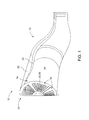
- a turbine system 10 having a combustor section 12 and a head end 14.
- the head end 14 is disposed at an adjacent upstream location of the combustor section 12 and includes a micromixer assembly 16.
- the micromixer assembly 16 includes a plate 17 having a plurality of sectors 18 which each comprise a plurality of tubes 20.
- the combustor section 12 is defined by an outer liner 22 that extends to an upstream end 24. Spaced radially outwardly of the outer liner 22, and surroundingly enclosing the outer liner 22, is a flow sleeve 26. A flow of air passes upstream within an air passage defined by the outer liner 22 and the flow sleeve 26 to the upstream end 24 of the outer liner 22.
- a top, cross-sectional view of a tube 20 of the plurality of tubes is illustrated within a receiving aperture 30 of the plate 17.
- the plate 17 includes a plurality of receiving apertures that extend relatively axially through the plate 17 and are each configured to have a receiving diameter 32 that is dimensioned to allow the tube 20 to be inserted therein.
- the tube 20 comprises an inner diameter 34, an outer diameter 36, an inlet 38 and an outlet 40. It is the outer diameter 36 of the tube 20 that is dimensioned to be inserted within the receiving diameter 32 of the receiving aperture 30.
- the tube 20 is typically formed of a durable material that is suitable for functioning in a region having a temperature that may exceed 1,600°F (871°C).
- Such a material may comprise stainless steel and/or a nickel-based alloy, such as Hastelloy® X. It is contemplated that a portion of a stainless steel tube may be formed of the Hastelloy® X material, such that only the non-stainless steel portion is disposed at the friction weld location, thereby providing a reliable portion of the tube 20 for enduring the aforementioned operation temperature.
- the plate 17 comprises a material having high-temperature strength, such as stainless steel, for example.
- the aforementioned materials are discussed as merely illustrative examples and are not to be understood as limiting.
- the inner diameter 34 of the tube 20 is dimensioned to receive an expander 50 that includes at least one expander head 52. Specifically, it is an outer diameter 54 of the expander head 52 that is to be closely dimensioned with that of the inner diameter 34 of the tube 20.
- the expander 50 comprises a shaft portion 56 that extends in a longitudinal direction 58 that relatively coincides with an axial direction of the turbine system 10, with the at least one expander head 52 disposed therealong.
- the function of the expander head 52 is to be controllably disposed at a position within the tube 20 that is desired to form a friction weld with the receiving aperture 30 of the plate 17, the method of which will be described in detail below.
- the expander 50 includes a plurality of expander heads. This provides the ability to form a plurality of friction welds between each tube 20 and receiving aperture 30.
- a flow diagram generally illustrates a method of assembling 60 the micromixer assembly 16.
- the method of assembling 60 comprises positioning the tube within the receiving aperture 62 and positioning the expander within the inner diameter of the tube 64.
- the expander 50 is situated to have the expander head 52, or the expander heads in the case of a plurality of friction welds as described above, disposed at a desired friction weld location.
- a rotor is operably connected to the tube and/or the expander shaft portion 68. The rotor is then rotated 70 and 50 to a predetermined speed that is sufficient to result in a generation of heat through mechanical friction between the outer diameter 36 of the tube 20 and the stationary receiving aperture 30 of the plate 17.
- the expander 50, and particularly the expander head 52 provides a radial force, known as an upset force, to displace and fuse the tube 20 to the receiving aperture 30.
- the expander 50 and the tube 20 may be rotated at speeds distinct from one another during the method of assembling 60. This may be accomplished by employing a gear system, such as a planetary gear, where various gear ratios may be achieved by manipulation of the input gear of the planetary gear.
- the tube 20 may rotate at a first speed, which is different than that of a second speed that the expander 50 may rotate at.
- the precise speeds used will vary depending on the specific application, but as an example, the first speed may be about 1,000 rpm, while the second speed may be about 950 rpm. It is to be understood that the illustrative speeds described above are not limiting and that the ratio and speeds will vary accordingly.
- Operation at suitable speeds provide a relative rotational speed for the expander 50, with respect to that of the tube 20 to generate an expanding effect, while avoiding excessive internal wall friction heat, which possibly leads to jointing the inner diameter 34 of the tube 20 to the expander 50.
- the expander 50 is removed from the inner diameter 34 of the tube 20.
- the expander 50 and inner diameter 34 of the tube 20 are lubricated and liquid cooled. It is to be understood that the above description for the method of assembling 60 is not intended to limit the precise order of operations, such that the method of assembling 60 may include a different order of operations based on numerous assembly factors.
- the method of assembly 60 provides the capability to form each friction weld in a matter of seconds, thereby significantly reducing the time required to mechanically join the tube 20 and the receiving aperture 30 of the plate 17, when compared to other processes employed to form such a mechanical joint, such as brazing, for example.
- the method of assembling 60 employs direct heat input at the friction weld interface, yielding relatively small heat-affected zones. Such benefits are particularly useful in a high temperature operation region, such as that of the micromixer assembly 16.
- the friction welding process also requires relatively brief preparation time, based on the tendency of the mechanical friction between the tube 20 and the receiving aperture 30 tending to clean the surface between the materials being welded. This is typically achieved when the aforementioned flash carries away dirt and debris that may have been present on a surface of the tube 20 and/or receiving aperture 30.
Landscapes
- Engineering & Computer Science (AREA)
- Chemical & Material Sciences (AREA)
- Combustion & Propulsion (AREA)
- Mechanical Engineering (AREA)
- General Engineering & Computer Science (AREA)
- Pressure Welding/Diffusion-Bonding (AREA)
Applications Claiming Priority (1)
| Application Number | Priority Date | Filing Date | Title |
|---|---|---|---|
| US13/449,012 US20130269351A1 (en) | 2012-04-17 | 2012-04-17 | Micromixer assembly of a turbine system and method of assembly |
Publications (1)
| Publication Number | Publication Date |
|---|---|
| EP2653784A2 true EP2653784A2 (de) | 2013-10-23 |
Family
ID=48095625
Family Applications (1)
| Application Number | Title | Priority Date | Filing Date |
|---|---|---|---|
| EP13163006.3A Withdrawn EP2653784A2 (de) | 2012-04-17 | 2013-04-09 | Mikromischeranordnung eines Turbinensystems und Montageverfahren |
Country Status (5)
| Country | Link |
|---|---|
| US (1) | US20130269351A1 (de) |
| EP (1) | EP2653784A2 (de) |
| JP (1) | JP2013221515A (de) |
| CN (1) | CN103375268A (de) |
| RU (1) | RU2013117265A (de) |
Families Citing this family (6)
| Publication number | Priority date | Publication date | Assignee | Title |
|---|---|---|---|---|
| US10619183B2 (en) | 2013-08-09 | 2020-04-14 | Kikkoman Corporation | Modified amadoriase and method for producing the same, agent for improving surfactant resistance of amadoriase and composition for measuring HbA1c using the same |
| US9581335B2 (en) | 2014-08-07 | 2017-02-28 | General Electric Company | Fuel nozzle tube retention |
| CN107148475A (zh) | 2014-10-24 | 2017-09-08 | 龟甲万株式会社 | 脱氢酶活性提高的阿马多里酶 |
| US10767866B2 (en) | 2018-07-11 | 2020-09-08 | General Electric Company | Micromixer for use with liquid fuel |
| KR102469577B1 (ko) | 2020-12-31 | 2022-11-21 | 두산에너빌리티 주식회사 | 마이크로 믹서 및 이를 포함하는 연소기 |
| KR102599921B1 (ko) | 2022-03-21 | 2023-11-07 | 두산에너빌리티 주식회사 | 연소기용 노즐, 연소기, 및 이를 포함하는 가스 터빈 |
Family Cites Families (5)
| Publication number | Priority date | Publication date | Assignee | Title |
|---|---|---|---|---|
| EP1456583B1 (de) * | 2001-12-20 | 2007-10-10 | Alstom Technology Ltd | Verfahren zum Eindüsen eines Brennstoff-/Luftgemisches in eine Brennkammer |
| US7114321B2 (en) * | 2003-07-31 | 2006-10-03 | General Electric Company | Thermal isolation device for liquid fuel components |
| EP2242865A1 (de) * | 2007-12-17 | 2010-10-27 | ExxonMobil Research and Engineering Company | Hochfeste nickellegierungsschweissverbindungen durch ausscheidungshärten |
| US8042339B2 (en) * | 2008-03-12 | 2011-10-25 | General Electric Company | Lean direct injection combustion system |
| US8439250B2 (en) * | 2009-07-01 | 2013-05-14 | Lockheed Martin Corporation | Friction-stir weld-tool and method |
-
2012
- 2012-04-17 US US13/449,012 patent/US20130269351A1/en not_active Abandoned
-
2013
- 2013-04-09 EP EP13163006.3A patent/EP2653784A2/de not_active Withdrawn
- 2013-04-12 JP JP2013083443A patent/JP2013221515A/ja active Pending
- 2013-04-16 RU RU2013117265/06A patent/RU2013117265A/ru not_active Application Discontinuation
- 2013-04-17 CN CN2013101332226A patent/CN103375268A/zh active Pending
Also Published As
| Publication number | Publication date |
|---|---|
| RU2013117265A (ru) | 2014-10-27 |
| CN103375268A (zh) | 2013-10-30 |
| JP2013221515A (ja) | 2013-10-28 |
| US20130269351A1 (en) | 2013-10-17 |
Similar Documents
| Publication | Publication Date | Title |
|---|---|---|
| EP2653784A2 (de) | Mikromischeranordnung eines Turbinensystems und Montageverfahren | |
| US10683952B2 (en) | Fluid couplings and methods for additive manufacturing thereof | |
| US9670784B2 (en) | Turbine bucket base having serpentine cooling passage with leading edge cooling | |
| US20180209280A1 (en) | Bladed disc and method of manufacturing the same | |
| US11846193B2 (en) | Turbine engine assembly | |
| CN107592904A (zh) | 受控的防漏燃烧器护环 | |
| JP6997556B2 (ja) | 多壁ブレードのためのプラットフォームコア供給部 | |
| EP3845783B1 (de) | Bürstendichtung mit formgedächtnislegierung | |
| JP6964463B2 (ja) | 多壁ブレードのための冷却回路 | |
| CN107035419B (zh) | 用于多壁叶片的平台核心供给冷却系统 | |
| JP6964462B2 (ja) | 多壁ブレードのための冷却回路 | |
| CN107989656B (zh) | 用于涡轮叶片的多匝冷却回路 | |
| EP3081762A2 (de) | Statische axiale bürstendichtung mit doppelborstenpacks | |
| JP2013231431A (ja) | ガスタービンエンジン用の分離可能なシールアセンブリ | |
| KR102851758B1 (ko) | 구성요소의 내부 통로에 대한 연장부를 갖는 폐쇄 요소 | |
| JP2001082170A (ja) | タービンロータ冷却回路の継手管 | |
| EP3189922B1 (de) | Erweiterte lötverbindung für rohr-zu-rohr-verbindung | |
| JP7536419B2 (ja) | マイクロミキサ管に耐摩耗性を伴うろうコーティングを提供する方法 | |
| EP3747583A1 (de) | Radial nach aussen gerichtete orbitalschweisstechnik als verbindungsverfahren, das für das innenrohr verwendet wird, um verbindungen in doppelwandrohrkonfigurationen anzubringen | |
| CA2808491C (en) | Friction welded turbine disk and shaft | |
| CN106415133B (zh) | 具有带中心线无共晶区的钎焊层的燃气涡轮发动机用燃烧器组件 |
Legal Events
| Date | Code | Title | Description |
|---|---|---|---|
| PUAI | Public reference made under article 153(3) epc to a published international application that has entered the european phase |
Free format text: ORIGINAL CODE: 0009012 |
|
| AK | Designated contracting states |
Kind code of ref document: A2 Designated state(s): AL AT BE BG CH CY CZ DE DK EE ES FI FR GB GR HR HU IE IS IT LI LT LU LV MC MK MT NL NO PL PT RO RS SE SI SK SM TR |
|
| AX | Request for extension of the european patent |
Extension state: BA ME |
|
| STAA | Information on the status of an ep patent application or granted ep patent |
Free format text: STATUS: THE APPLICATION IS DEEMED TO BE WITHDRAWN |
|
| 18D | Application deemed to be withdrawn |
Effective date: 20151103 |