EP2653746A2 - Elastomer bearing for use as a bearing for a rod-shaped stabilising bearing element - Google Patents
Elastomer bearing for use as a bearing for a rod-shaped stabilising bearing element Download PDFInfo
- Publication number
- EP2653746A2 EP2653746A2 EP13160071.0A EP13160071A EP2653746A2 EP 2653746 A2 EP2653746 A2 EP 2653746A2 EP 13160071 A EP13160071 A EP 13160071A EP 2653746 A2 EP2653746 A2 EP 2653746A2
- Authority
- EP
- European Patent Office
- Prior art keywords
- bearing
- elastomeric
- adhesive
- elastomer
- rod
- Prior art date
- Legal status (The legal status is an assumption and is not a legal conclusion. Google has not performed a legal analysis and makes no representation as to the accuracy of the status listed.)
- Withdrawn
Links
Images
Classifications
-
- B—PERFORMING OPERATIONS; TRANSPORTING
- B60—VEHICLES IN GENERAL
- B60G—VEHICLE SUSPENSION ARRANGEMENTS
- B60G21/00—Interconnection systems for two or more resiliently-suspended wheels, e.g. for stabilising a vehicle body with respect to acceleration, deceleration or centrifugal forces
- B60G21/02—Interconnection systems for two or more resiliently-suspended wheels, e.g. for stabilising a vehicle body with respect to acceleration, deceleration or centrifugal forces permanently interconnected
- B60G21/04—Interconnection systems for two or more resiliently-suspended wheels, e.g. for stabilising a vehicle body with respect to acceleration, deceleration or centrifugal forces permanently interconnected mechanically
- B60G21/05—Interconnection systems for two or more resiliently-suspended wheels, e.g. for stabilising a vehicle body with respect to acceleration, deceleration or centrifugal forces permanently interconnected mechanically between wheels on the same axle but on different sides of the vehicle, i.e. the left and right wheel suspensions being interconnected
- B60G21/055—Stabiliser bars
- B60G21/0551—Mounting means therefor
-
- F—MECHANICAL ENGINEERING; LIGHTING; HEATING; WEAPONS; BLASTING
- F16—ENGINEERING ELEMENTS AND UNITS; GENERAL MEASURES FOR PRODUCING AND MAINTAINING EFFECTIVE FUNCTIONING OF MACHINES OR INSTALLATIONS; THERMAL INSULATION IN GENERAL
- F16F—SPRINGS; SHOCK-ABSORBERS; MEANS FOR DAMPING VIBRATION
- F16F1/00—Springs
- F16F1/02—Springs made of steel or other material having low internal friction; Wound, torsion, leaf, cup, ring or the like springs, the material of the spring not being relevant
- F16F1/14—Torsion springs consisting of bars or tubes
- F16F1/16—Attachments or mountings
-
- B—PERFORMING OPERATIONS; TRANSPORTING
- B60—VEHICLES IN GENERAL
- B60G—VEHICLE SUSPENSION ARRANGEMENTS
- B60G2204/00—Indexing codes related to suspensions per se or to auxiliary parts
- B60G2204/10—Mounting of suspension elements
- B60G2204/12—Mounting of springs or dampers
- B60G2204/122—Mounting of torsion springs
- B60G2204/1222—Middle mounts of stabiliser on vehicle body or chassis
-
- F—MECHANICAL ENGINEERING; LIGHTING; HEATING; WEAPONS; BLASTING
- F16—ENGINEERING ELEMENTS AND UNITS; GENERAL MEASURES FOR PRODUCING AND MAINTAINING EFFECTIVE FUNCTIONING OF MACHINES OR INSTALLATIONS; THERMAL INSULATION IN GENERAL
- F16F—SPRINGS; SHOCK-ABSORBERS; MEANS FOR DAMPING VIBRATION
- F16F2226/00—Manufacturing; Treatments
- F16F2226/04—Assembly or fixing methods; methods to form or fashion parts
- F16F2226/042—Gluing
Definitions
- the invention relates to an elastomeric bearing for supporting a stabilizer designed as a rod-shaped bearing element according to the preamble of patent claim 1 and a bearing assembly using such an elastomeric bearing according to claim 8.
- Generic elastomeric bearings or bearing arrangements are used in addition to the storage of stabilizers, for example, for the storage of handlebar components in chassis of motor vehicles.
- the stabilizers are usually delivered either with pre-assembled and materially connected to the stabilizer elastomer bearings or the assembly of elastomeric bearings and stabilizer takes place in the course of attachment of the stabilizer on the subframe or on the body.
- Cohesive connections between stabilizer and elastomeric bearings are realized by vulcanization or by bonding.
- a generic elastomeric bearing is known that is connected via an adhesive bond with a stabilizer.
- the joints of stabilizer and / or elastomeric bearings are coated with a spreadable or sprayable dispersion of a solvent and a microencapsulated adhesive to prepare the bond.
- the joining partners are subjected to pressure and / or a relative movement to each other to destroy a part or all of the microcapsules and release the adhesive therein.
- a fixation of, for example, 10 to 15 minutes duration and a subsequent several hours curing time a permanent connection between the elastomeric bearing and stabilizer or chassis member is given.
- the object of the invention is to provide an elastomer bearing, the process reliable and by the realization of short cycle times at the same time can be economically connected to the designed as a stabilizer rod-shaped bearing element.
- a bearing assembly for supporting a designed as a stabilizer rod-shaped bearing element to be provided using such an elastomeric bearing is provided using such an elastomeric bearing.
- the invention accordingly provides an elastomeric bearing for supporting a rod-shaped bearing element designed as a stabilizer, wherein the elastomeric bearing has at least one elastomeric body which comprises a receiving region for receiving the rod-shaped bearing element.
- This receiving region is designed such that the elastomeric body can enclose the bearing element and wherein the receiving region of the elastomeric body is provided with an adhesive for producing an at least indirect adhesive bond between the elastomeric body and the rod-shaped bearing element.
- the invention proposes that the adhesive is formed, at least in the initial state, as a permanently tacky PSA present in the solid state.
- initial state in this context means the state of the adhesive at the time of joining the elastomeric body and the rod-shaped bearing element.
- the invention makes it possible to reduce production cycle times since no waiting times required by a necessary evaporation of solvents or other waiting times necessary for a curing process are required. process-related Fixing phases do not occur except for a brief pressing after the joining process.
- the outer circumference of the elastomer body may be substantially round or even deviate from the circular shape.
- the opening penetrating the elastomeric body for receiving the stabilizer constitutes the receiving area and is generally column-shaped, preferably cylindrical.
- the elastomeric body is fully vulcanized during its production. A subsequent vulcanization after joining with the stabilizer is not required.
- the torsion angle to be absorbed by the elastomer body with a pivoting of the stabilizer caused by the driving operation is in the range of about 10 ° to 60 °.
- the elastomeric body preferably has a hardness of 50 to 60 Shore.
- a soft, elastic bearing body enables the required rotational degree of freedom through intermolecular shear deformation. In the torsional load of the ElasomerSystems should no tensile stresses occur in the elastomer, as they can significantly reduce the life of the elastomer body. In order to avoid undesirable tensile stresses occurring in the elastomer body during driving, this is mounted with a bias voltage.
- the volume of the relaxed elastomer body is therefore greater than the volume of the elastomeric body in the installed state.
- the required to adjust the bias excess of Elastomer Economics- blank is to choose at least as large that in the installed state at maximum torsion angle still no harmful tensile stresses in the elastomer occur.
- the elastomeric body can be made in one piece or in several parts.
- the one-piece design may have a slot which cuts through the wall at a position in the axial and radial directions, in order to permit mounting in the radial direction by attachment to the stabilizer. It may be advantageous to form the elastomeric body in two parts with a parting plane running through the central axis of the opening for receiving the stabilizer, in order to simplify the assembly and the application of the pressure-sensitive adhesive. Multi-part designs may be required due to manufacturing reasons or space requirements. By geometrically differently shaped and / or elastomeric body segments produced from different elastomer materials can be adjusted direction-dependent damping properties.
- Pressure-sensitive adhesives are highly viscous and permanently tacky on delivery. After application to the splice, the adhesive bond is made by squeezing the components to be joined. Pressure-sensitive adhesives are offered, inter alia, as a so-called transfer adhesive and can be obtained commercially, for example in the form of double-sided adhesive tape, on waxed transfer paper.
- Acrylic pressure-sensitive tapes are very often used for industrial applications. These have a high temperature stability and a high resistance to solvents and oily substances. In addition, acrylate PSAs have proven to be resistant to aging and weathering under the influence of oxygen or ozone.
- the adhesive may preferably be applied over the surface of the elastomeric body adjacent to the receiving region or onto the stabilizer in a planar manner. If necessary, the surfaces should be dried by suitable pre-treatment measures prior to the application of the adhesive and should be free from any possible residues of grease and dust or dirt particles.
- the stabilizer surface usually has a powder coating or is formed by a cathaphoretic dip coating (KTL).
- KTL cathaphoretic dip coating
- the PSA is applied advantageously without further pretreatment measures immediately after vulcanization on the adjacent to the receiving area surface of the elastomer body. If the adhesive is applied only some time after vulcanization, a pre-treatment of the elastomer surface is required to a negative effect on the Adhesive adhesion by temporarily out of the elastomer out-diffused ingredients to avoid.
- the PSA is preferably flat as at least one side, but advantageously formed on both sides by separating materials enclosed film with a layer thickness of about 0.1 to 0.5 millimeters. In this way, a uniform application of adhesive and the dosage of a precisely matched to the adhesive coat amount of adhesive is possible. A lateral leakage of excess adhesive from the joint and penetration of dirt and moisture in the junction of elastomeric body and stabilizer at too low an amount of adhesive are avoided.
- the PSA As prefabricated to the respective splice, enclosed on both sides by release materials adhesive pads or diecuts.
- the cover is peeled off.
- the application should be done by means of a device.
- the release material may be provided on one or both sides with a tab overhanging the edge of the adhesive pad.
- the receiving area of the elastomeric body comprises a tubular receiving element for receiving the rod-shaped bearing element.
- the tubular receiving element may preferably be divided in its longitudinal extension into a plurality of sub-elements, for example in two half-shells. Such a division improves accessibility for the application of the pressure-sensitive adhesive to the inner sides of the cup-shaped parts of the receiving element.
- the tubular design of the receiving element is not limited to circular cross-sections. It may also be advantageous to use cross sections which deviate from the circular shape, for example oval cross sections or polygonal profiles.
- the tubular receiving element can be adapted to the contour of the opposite joining region of the stabilizer. It may also be advantageous to deviate the tubular receiving element in the not yet bonded state from the geometry of the opposite adhesive surface of the stabilizer in order to adjust in the mounted final state in the vehicle desired bias conditions in the elastomeric body by the elasticity of the material used for the tubular receiving element.
- the elastomeric body and the tubular receiving element form a Vulkanisationsverbund.
- the tubular receiving element is formed from a metal material, a plastic or a hybrid material.
- metal materials for the tubular receiving elements are preferably materials based on steel or aluminum.
- the elastomeric body has at least one stiffening element.
- the stiffening element By the stiffening element, the stiffness of the elastomeric bearing can be increased in the radial direction. This is particularly desirable when using the elastomeric bearing for supporting a stabilizer.
- the aforementioned radial direction corresponds in this case in the vehicle installed in the final state of the vehicle longitudinal direction and the vehicle vertical direction.
- the stiffening element may preferably consist of a metal material, is at least substantially embedded in the elastomer of the elastomer body and arranged concentrically to the central axis of the elastomer body.
- the one or more stiffening elements may be flat or shell-shaped, in particular as a longitudinal section of a cylinder wall, or tubular.
- the stiffening elements distributed on their surfaces have several openings in the form of holes or punched holes.
- the elastomer if it is present in a liquid state during vulcanization, from one side of a Pass stiffening over the openings to the other side and so better "flow around" the stiffening elements on all sides, whereby an intimate connection between the elastomer and the stiffening elements can be made.
- the stiffening elements can also be contoured, for example, by the introduction of stiffening beads executed.
- a design of the elastomeric bearing with two elastomeric bodies is embedded in each of which a stiffening element such that the two stiffening elements in the assembled final state in the vehicle substantially form a cylinder.
- the peripheral portions according to the DE 100 49 611 C2 have a non-linear, mutually complementary edge profile.
- the adhesive preferably has a carrier.
- the strength of the adhesive film can be increased and thus the handling can be simplified.
- the properties of the adhesive bond can be positively influenced.
- carrier material for example, fabrics, nonwovens or knitted fabrics can be used.
- the adhesive is present in a first and a second adhesive layer, wherein the two adhesive layers have different compositions.
- the carrier is preferably arranged substantially centrally between the two adhesive layers.
- the proposed bearing arrangement for a chassis of a motor vehicle comprises an elastomer bearing as described above and a fixed in the receiving area of the elastomeric bearing by the adhesive rod-shaped bearing element.
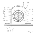
- Fig. 1 shows an elastomer bearing 1 with a stored therein, in section stabilizer 3 with a circular cross-section. This arrangement forms a bearing arrangement 5.
- the elastomer bearing 1 can generally be used for supporting rod-shaped bearing elements 3.
- the elastomeric bearing 1 has an elastomeric body 7.
- the elastomeric body 7 is divided in the embodiment in two halves 7a, 7b.
- the opening 7 penetrating the elastomer body 7 for receiving the stabilizer 3 represents the receiving area 9.
- the receiving area 9 is subdivided into two partial areas 9a, 9b in the exemplary embodiment, which are formed by two recesses in the elastomeric body 7 in the form of half-divided cylinders.
- the recesses are assigned to the elastomer body halves 7a, 7b.
- a tubular receiving element 11 is arranged on the inside of the circumference. This tubular receiving element 11 is also divided into two shell-shaped halves 11a, 11b, which in turn are associated with the subregions 9a and 9b.
- the receiving element 11 is connected by vulcanization with the elastomeric body 7.
- the stabilizer 3 is completely enclosed by the receiving element 11.
- the receiving element 11 consists of a metal material based on steel. It can also be formed of aluminum, plastic or a hybrid material.
- an adhesive 13 is arranged between the receiving element 11 and the stabilizer 3.
- the adhesive 13 is in the form of an adhesive layer 13, which substantially completely fills the space between the two joining partners stabilizer 3 and receiving element 11.
- the two joining partners are connected to each other substantially rotationally fixed.
- the elasticity of the adhesive layer 13 is negligible.
- Through the adhesive layer 13 a cohesive connection between the joining partners is made by their strength is ensured that the introduced via the stabilizer 3 and the receiving element 11 in the elastomer body 7 forces and moments are transmitted securely.
- the torsional movements of the stabilizer 3 while driving are absorbed by the elastomer of the elastomer body.
- the adhesive layer 13 is not shown to scale for illustrative purposes. The thickness of the adhesive layer 13 is actually in the tenth of a millimeter range or even lower.
- the adhesive 13 is formed as a pressure-sensitive adhesive 13 based on acrylate and is present in one layer without a carrier. It is likewise possible to use acrylate-based pressure-sensitive adhesives 13 which are multilayered without support or arranged on a support on both sides, it being possible for the two pressure-sensitive adhesives 13 in the latter case to have the same or different composition.
- the elastomer body enclosing the stabilizer 3 is in the in Fig. 1 shown installation state bordered by a ⁇ -shaped bracket 15 circumferentially.
- the bracket 15 is connected via through holes in the tabs of the bracket 15 with a vehicle body 17, which is only indicated schematically here. This is usually done by screw 19, which are also indicated here only schematically.
- the encapsulation of the elastomeric body 7 can also be effected by two substantially identical clamps, which embrace the elastomeric body 7 approximately in half. Such clamps are for example from the DE 10 2010 033 036 A1 known.
- the clamps or brackets 15 required for fastening the stabilizer 3 accommodated by the elastomeric body 7 preferably have beads extending in the circumferential direction, which, together with the form of corresponding recesses in the elastomeric body 7, counteract a wandering of the built-in stabilizer 3 in the vehicle transverse direction.
- the volume of the relaxed elastomer body 7 is therefore greater than the volume of the elastomeric body 7 in the installed state.
- the volume difference 21 between relaxed and installed state is indicated schematically.
- a tubular reinforcing element 23 is substantially completely embedded.
- the tubular reinforcing element 23 is divided into two shell-shaped halves 23a, 23b.
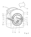
- FIG. 2 the elastomeric body 7 is shown in perspective. It can be seen that the receiving element 11 and the stiffening element 23 frontally slightly protruding from the elastomeric body 7. This has manufacturing reasons.
- the indicated adhesive layer 13 is protected in the delivery state of the elastomeric body 7 by a schematically shown, already withdrawn cover 27 made of a release material.
- bead-shaped recesses 29 extending in the vehicle longitudinal direction in the installed state, which are matched to the geometry of the bracket 15 in this area, can be seen.
- grooves 31 with a semicircular cross section are provided between the two aforementioned components on the left and right sides. These grooves 31 are required by the production and are in the in Fig. 1 illustrated biased state of the elastomeric body 7 closed by the bias again.
- the two-part construction of the elastomer body 7 shown in the exemplary embodiment with the components connected to it offers on the one hand the advantage that good accessibility for the application of the adhesive layer 13 is provided. On the other hand, the assembly with the stabilizer 3 is facilitated by the split structure.
Abstract
Description
Die Erfindung betrifft ein Elastomerlager zur Lagerung eines als Stabilisator ausgebildeten stabförmigen Lagerelements gemäß dem Oberbegriff des Patentanspruchs 1 und eine Lageranordnung unter Verwendung eines solchen Elastomerlagers gemäß Patentanspruch 8.The invention relates to an elastomeric bearing for supporting a stabilizer designed as a rod-shaped bearing element according to the preamble of patent claim 1 and a bearing assembly using such an elastomeric bearing according to claim 8.
Gattungsgemäße Elastomerlager bzw. Lageranordnungen werden neben der Lagerung von Stabilisatoren beispielsweise auch zur Lagerung von Lenkerbauteilen in Fahrwerken von Kraftfahrzeugen eingesetzt. In der Praxis werden die Stabilisatoren zumeist entweder mit vormontierten und stoffschlüssig mit dem Stabilisator verbundenen Elastomerlagern ausgeliefert oder die Montage von Elastomerlager und Stabilisator erfolgt im Zuge der Befestigung des Stabilisators am Hilfsrahmen oder an der Karosserie.Generic elastomeric bearings or bearing arrangements are used in addition to the storage of stabilizers, for example, for the storage of handlebar components in chassis of motor vehicles. In practice, the stabilizers are usually delivered either with pre-assembled and materially connected to the stabilizer elastomer bearings or the assembly of elastomeric bearings and stabilizer takes place in the course of attachment of the stabilizer on the subframe or on the body.
Stoffschlüssige Verbindungen zwischen Stabilisator und Elastomerlager werden durch Vulkanisation oder durch Klebungen realisiert.Cohesive connections between stabilizer and elastomeric bearings are realized by vulcanization or by bonding.
Aus der
Aufgabe der Erfindung ist es, ein Elastomerlager bereitzustellen, das prozesssicher und durch die Realisierung von kurzen Zykluszeiten zugleich wirtschaftlich mit dem als Stabilisator ausgebildeten stabförmigen Lagerelement verbunden werden kann. Gleichzeitig soll eine Lageranordnung zur Lagerung eines als Stabilisator ausgebildeten stabförmigen Lagerelements unter Verwendung eines solchen Elastomerlagers bereitgestellt werden.The object of the invention is to provide an elastomer bearing, the process reliable and by the realization of short cycle times at the same time can be economically connected to the designed as a stabilizer rod-shaped bearing element. At the same time a bearing assembly for supporting a designed as a stabilizer rod-shaped bearing element to be provided using such an elastomeric bearing.
Diese Aufgabe wird gemäß einem ersten Aspekt der vorliegenden Erfindung gelöst durch ein gattungsgemäßes Elastomerlager, welches zusätzlich die kennzeichnenden Merkmale des Patentanspruchs 1 aufweist.This object is achieved according to a first aspect of the present invention by a generic elastomeric bearing, which additionally has the characterizing features of claim 1.
Gemäß einem zweiten Aspekt wird die Aufgabe durch eine Lageranordnung gelöst, welche die Merkmale des Patentanspruchs 8 aufweist.According to a second aspect, the object is achieved by a bearing arrangement which has the features of patent claim 8.
Bevorzugte Ausführungsformen und Weiterbildungen sind Gegenstand der Unteransprüche.Preferred embodiments and further developments are the subject of the dependent claims.
Die Erfindung sieht demnach ein Elastomerlager zur Lagerung eines als Stabilisator ausgebildeten stabförmigen Lagerelements vor, wobei das Elastomerlager zumindest einen Elastomerkörper aufweist, der einen Aufnahmebereich zur Aufnahme des stabförmigen Lagerelements umfasst. Dieser Aufnahmebereich ist derart ausgeführt, dass der Elastomerkörper das Lagerelement umschließen kann und wobei der Aufnahmebereich des Elastomerkörpers mit einem Klebemittel zur Herstellung einer zumindest mittelbaren Klebeverbindung zwischen dem Elastomerkörper und dem stabförmigen Lagerelement versehen ist. Die Erfindung schlägt vor, dass das Klebemittel zumindest im Ausgangszustand als im festen Aggregatzustand vorliegende, dauerklebrige Haftklebemasse ausgebildet ist.The invention accordingly provides an elastomeric bearing for supporting a rod-shaped bearing element designed as a stabilizer, wherein the elastomeric bearing has at least one elastomeric body which comprises a receiving region for receiving the rod-shaped bearing element. This receiving region is designed such that the elastomeric body can enclose the bearing element and wherein the receiving region of the elastomeric body is provided with an adhesive for producing an at least indirect adhesive bond between the elastomeric body and the rod-shaped bearing element. The invention proposes that the adhesive is formed, at least in the initial state, as a permanently tacky PSA present in the solid state.
Unter dem Begriff Ausgangszustand ist in diesem Zusammenhang der Zustand des Klebemittels zum Zeitpunkt des Fügens von Elastomerkörper und stabförmigem Lagerelement zu verstehen.The term initial state in this context means the state of the adhesive at the time of joining the elastomeric body and the rod-shaped bearing element.
Durch die Erfindung wird es möglich, Fertigungstaktzeiten zu reduzieren, da keine durch ein notwendiges Verdunsten von Lösungsmitteln oder sonstige für einen Aushärtungsprozess notwendige Wartezeiten erforderlich sind. Prozessbedingte Fixierphasen fallen bis auf ein kurzzeitiges Andrücken nach dem Fügevorgang nicht an.The invention makes it possible to reduce production cycle times since no waiting times required by a necessary evaporation of solvents or other waiting times necessary for a curing process are required. process-related Fixing phases do not occur except for a brief pressing after the joining process.
Der Außenumfang des Elastomerkörpers kann im Wesentlichen rund sein oder auch von der Kreisform abweichen. Die den Elastomerkörper durchdringende Öffnung zur Aufnahme des Stabilisators stellt den Aufnahmebereich dar und ist in der Regel säulenförmig, vorzugsweise zylinderförmig, ausgebildet. Der Elastomerkörper wird im Rahmen seiner Herstellung vollständig ausvulkanisiert. Ein späteres Nachvulkanisieren nach dem Fügen mit dem Stabilisator ist nicht erforderlich.The outer circumference of the elastomer body may be substantially round or even deviate from the circular shape. The opening penetrating the elastomeric body for receiving the stabilizer constitutes the receiving area and is generally column-shaped, preferably cylindrical. The elastomeric body is fully vulcanized during its production. A subsequent vulcanization after joining with the stabilizer is not required.
Der durch den Elastomerkörper aufzunehmende Torsionswinkel bei einer durch den Fahrbetrieb bedingten Schwenkung des Stabilisators liegt im Bereich von etwa 10° bis 60°. Der Elastomerkörper weist bevorzugt eine Härte von 50 bis 60 Shore auf. Ein weicher, elastischer Lagerkörper ermöglicht durch intermolekulare Schubverformung den geforderten rotatorischen Freiheitsgrad. Bei der Torsionsbelastung des Elasomerkörpers sollten in dem Elastomer keine Zugspannungen auftreten, da diese die Lebensdauer des Elastomerkörpers erheblich herabsetzen können. Um zu vermeiden, dass während des Fahrbetriebes unerwünschte Zugspannungen im Elastomerkörper auftreten, wird dieser mit einer Vorspannung montiert. Das Volumen des entspannten Elastomerkörpers ist daher größer als das Volumen des Elastomerkörpers im verbauten Zustand. Das zur Einstellung der Vorspannung erforderliche Übermaß des Elastomerkörper- Rohlings ist dabei mindestens so groß zu wählen, dass im Einbauzustand bei maximal möglichem Torsionswinkel noch keine schädlichen Zugspannungen im Elastomer auftreten.The torsion angle to be absorbed by the elastomer body with a pivoting of the stabilizer caused by the driving operation is in the range of about 10 ° to 60 °. The elastomeric body preferably has a hardness of 50 to 60 Shore. A soft, elastic bearing body enables the required rotational degree of freedom through intermolecular shear deformation. In the torsional load of the Elasomerkörpers should no tensile stresses occur in the elastomer, as they can significantly reduce the life of the elastomer body. In order to avoid undesirable tensile stresses occurring in the elastomer body during driving, this is mounted with a bias voltage. The volume of the relaxed elastomer body is therefore greater than the volume of the elastomeric body in the installed state. The required to adjust the bias excess of Elastomerkörper- blank is to choose at least as large that in the installed state at maximum torsion angle still no harmful tensile stresses in the elastomer occur.
Der Elastomerkörper kann einteilig oder mehrteilig ausgeführt sein. Die einteilige Ausführung kann einen die Wandung an einer Stelle in axialer und radialer Richtung durchtrennenden Schlitz aufweisen, um eine Montage durch Aufstecken auf den Stabilisator in radialer Richtung zu ermöglichen. Es kann vorteilhaft sein, den Elastomerkörper zur Vereinfachung der Montage und des Aufbringens der Haftklebemasse zweiteilig mit einer durch die Mittelachse der Öffnung zur Aufnahme des Stabilisators verlaufenden Trennebene auszubilden. Mehrteilige Ausführungen können aus Herstellungsgründen oder Bauraum bedingt erforderlich sein. Durch geometrisch unterschiedlich gestaltete und / oder aus unterschiedlichen Elastomerwerkstoffen hergestellte Elastomerkörper- Segmente lassen sich richtungsabhängige Dämpfungseigenschaften einstellen.The elastomeric body can be made in one piece or in several parts. The one-piece design may have a slot which cuts through the wall at a position in the axial and radial directions, in order to permit mounting in the radial direction by attachment to the stabilizer. It may be advantageous to form the elastomeric body in two parts with a parting plane running through the central axis of the opening for receiving the stabilizer, in order to simplify the assembly and the application of the pressure-sensitive adhesive. Multi-part designs may be required due to manufacturing reasons or space requirements. By geometrically differently shaped and / or elastomeric body segments produced from different elastomer materials can be adjusted direction-dependent damping properties.
Haftklebemassen liegen im Anlieferzustand hochviskos und dauerklebrig vor. Nach dem Aufbringen auf die Klebestelle wird die Klebeverbindung durch Zusammendrücken der zu verbindenden Bauteile hergestellt. Haftklebemassen werden unter anderem als sogenannter Transferklebstoff angeboten und können im Handel beispielsweise in Form von doppelseitigem Klebeband auf gewachstem Transferpapier bezogen werden.Pressure-sensitive adhesives are highly viscous and permanently tacky on delivery. After application to the splice, the adhesive bond is made by squeezing the components to be joined. Pressure-sensitive adhesives are offered, inter alia, as a so-called transfer adhesive and can be obtained commercially, for example in the form of double-sided adhesive tape, on waxed transfer paper.
In Versuchen hat sich für die Verbindung von Elastomerkörper und Stabilisator eine Haftklebemasse auf Acrylat-Basis als besonders geeignet erwiesen.In experiments, a pressure-sensitive adhesive based on acrylate has proven to be particularly suitable for the combination of elastomer body and stabilizer.
Für industrielle Anwendungen werden sehr häufig Acrylathaftklebebänder eingesetzt. Diese weisen eine hohe Temperaturstabilität sowie eine hohe Beständigkeit gegen Lösemittel und ölhaltige Stoffe auf. Acrylathaftklebemassen haben darüber hinaus als unter Sauerstoff- oder Ozoneinfluss alterungsbeständig und witterungsstabil erwiesen.Acrylic pressure-sensitive tapes are very often used for industrial applications. These have a high temperature stability and a high resistance to solvents and oily substances. In addition, acrylate PSAs have proven to be resistant to aging and weathering under the influence of oxygen or ozone.
Das Klebemittel kann auf die an den Aufnahmebereich grenzende Oberfläche des Elastomerkörpers oder auf den Stabilisator bevorzugt flächig aufgetragen werden. Die Oberflächen sind durch geeignete Vorbehandlungsmaßnahmen vor dem Klebemittelauftrag gegebenenfalls zu trocknen und von möglicherweise vorhandenen Fettrückständen sowie Staub- oder Schmutzpartikeln zu befreien. Die Stabilisatoroberfläche weist in der Regel eine Pulverbeschichtung auf oder wird durch eine kathaphoresische Tauchlackierung (KTL) gebildet. Die Haftklebemasse wird vorteilhaft ohne weitere Vorbehandlungsmaßnahmen unmittelbar nach dem Vulkanisieren auf die an den Aufnahmebereich grenzende Oberfläche des Elastomerkörpers aufgebracht. Wird das Klebemittel erst einige Zeit nach der Vulkanisation aufgetragen, ist eine vorherige Vorbehandlung der Elastomeroberfläche erforderlich, um eine negative Beeinflussung der Klebemittelhaftung durch zwischenzeitlich aus dem Elastomer herausdiffundierte Inhaltsstoffe zu vermeiden.The adhesive may preferably be applied over the surface of the elastomeric body adjacent to the receiving region or onto the stabilizer in a planar manner. If necessary, the surfaces should be dried by suitable pre-treatment measures prior to the application of the adhesive and should be free from any possible residues of grease and dust or dirt particles. The stabilizer surface usually has a powder coating or is formed by a cathaphoretic dip coating (KTL). The PSA is applied advantageously without further pretreatment measures immediately after vulcanization on the adjacent to the receiving area surface of the elastomer body. If the adhesive is applied only some time after vulcanization, a pre-treatment of the elastomer surface is required to a negative effect on the Adhesive adhesion by temporarily out of the elastomer out-diffused ingredients to avoid.
Es kann vorteilhaft sein, das Klebemittel sowohl auf die an den Aufnahmebereich grenzende Oberfläche des Elastomerkörpers als auch auf den Stabilisator aufzutragen. Durch das Aufbringen von Haftklebemassen unterschiedlicher, auf die jeweilige Oberfläche abgestimmter und untereinander verträglicher Zusammensetzung auf die beiden vorgenannten Fügepartner lassen sich gute Haftungseigenschaften erzielen.It can be advantageous to apply the adhesive both to the surface of the elastomer body adjacent to the receiving region and to the stabilizer. By applying pressure-sensitive adhesives of different, matched to the respective surface and mutually compatible composition on the two aforementioned joining partners can be achieved good adhesion properties.
Aus Handhabungsgründen ist es vorteilhaft, die Haftklebemasse auf eine Abdeckung aus einem Trennmaterial aufzubringen. Derartige Trennmaterialien werden auch als Releaseliner oder Liner bezeichnet. Für den vorgenannten Anwendungsfall ist die Haftklebemasse bevorzugt flächig als zumindest einseitig, vorteilhaft jedoch beidseitig durch Trennmaterialien eingeschlossener Film mit einer Schichtdicke von ca. 0,1 bis 0,5 Millimeter ausgebildet. Auf diese Weise ist ein gleichmäßiger Kleberauftrag und die Dosierung einer exakt auf den Klebefall abgestimmte Klebemittelmenge möglich. Ein seitliches Austreten von überschüssigem Klebemittel aus der Fügestelle sowie ein Eindringen von Schmutz und Feuchtigkeit in die Verbindungsstelle von Elastomerkörper und Stabilisator bei zu geringer Klebemittelmenge werden dadurch vermieden. Für eine automatisierte Verarbeitung bietet es sich an, die Haftklebemasse als vorkonfektioniert auf die jeweilige Klebestelle abgestimmte, beidseitig durch Trennmaterialien eingeschlossene Klebepads oder Stanzlinge bereitzustellen. Unmittelbar vor dem Aufbringen des Klebepads auf die vorbereitete Klebestelle des Elastomerkörpers oder des Stabilisators wird die Abdeckung abgezogen. Um eine exakte Positionierung des Klebepads zu der Klebestelle sicherstellen zu können, sollte das Aufbringen mit Hilfe einer Vorrichtung erfolgen. Um das Abziehen der Klebemittelabdeckung zu erleichtern, kann das Trennmaterial auf einer oder auf beiden Seiten mit einer über den Rand des Klebepads überstehenden Lasche versehen sein.For reasons of handling, it is advantageous to apply the pressure-sensitive adhesive to a cover made of a release material. Such release materials are also referred to as release liners or liners. For the aforementioned application, the PSA is preferably flat as at least one side, but advantageously formed on both sides by separating materials enclosed film with a layer thickness of about 0.1 to 0.5 millimeters. In this way, a uniform application of adhesive and the dosage of a precisely matched to the adhesive coat amount of adhesive is possible. A lateral leakage of excess adhesive from the joint and penetration of dirt and moisture in the junction of elastomeric body and stabilizer at too low an amount of adhesive are avoided. For automated processing, it is advisable to provide the PSA as prefabricated to the respective splice, enclosed on both sides by release materials adhesive pads or diecuts. Immediately before the application of the adhesive pad on the prepared splice of the elastomeric body or the stabilizer, the cover is peeled off. In order to ensure an exact positioning of the adhesive pad to the splice, the application should be done by means of a device. To facilitate removal of the adhesive cover, the release material may be provided on one or both sides with a tab overhanging the edge of the adhesive pad.
In vorteilhafter Weiterbildung der Erfindung umfasst der Aufnahmebereich des Elastomerkörpers ein rohrförmiges Aufnahmeelement zur Aufnahme des stabförmigen Lagerelements.In an advantageous embodiment of the invention, the receiving area of the elastomeric body comprises a tubular receiving element for receiving the rod-shaped bearing element.
Durch die Anordnung des rohrförmigen Aufnahmeelements zwischen Elastomerkörper und Stabilisator wird eine weitere Versteifung des Verbindungsbereichs erreicht. Das rohrförmige Aufnahmeelement kann vorzugsweise in seiner Längserstreckung in mehrere Teilelemente geteilt sein, beispielsweise in zwei Halbschalen. Durch eine solche Teilung wird zu Zugänglichkeit für das Auftragen der Haftklebemasse auf die Innenseiten der schalenförmigen Teile des Aufnahmeelements verbessert. Die rohrförmige Ausbildung des Aufnahmeelements ist nicht auf kreisrunde Querschnitte beschränkt. Es kann auch vorteilhaft sein, von der Kreisform abweichende Querschnitte, beispielsweise ovale Querschnitte oder Polygonprofile, zu verwenden.The arrangement of the tubular receiving element between the elastomer body and stabilizer a further stiffening of the connecting portion is achieved. The tubular receiving element may preferably be divided in its longitudinal extension into a plurality of sub-elements, for example in two half-shells. Such a division improves accessibility for the application of the pressure-sensitive adhesive to the inner sides of the cup-shaped parts of the receiving element. The tubular design of the receiving element is not limited to circular cross-sections. It may also be advantageous to use cross sections which deviate from the circular shape, for example oval cross sections or polygonal profiles.
Das rohrförmige Aufnahmeelement kann an die Kontur des gegenüberliegenden Fügebereichs des Stabilisators angepasst sein. Es kann auch vorteilhaft sein, das rohrförmige Aufnahmeelement im noch nicht verklebten Zustand von der Geometrie der gegenüberliegenden Klebefläche des Stabilisators abweichend auszuführen, um in dem montierten Endzustand im Fahrzeug gewünschte Vorspannungsverhältnisse im Elastomerkörper durch die Elastizität des für das rohrförmige Aufnahmeelement verwendeten Werkstoffes einstellen zu können.The tubular receiving element can be adapted to the contour of the opposite joining region of the stabilizer. It may also be advantageous to deviate the tubular receiving element in the not yet bonded state from the geometry of the opposite adhesive surface of the stabilizer in order to adjust in the mounted final state in the vehicle desired bias conditions in the elastomeric body by the elasticity of the material used for the tubular receiving element.
Vorteilhaft bilden der Elastomerkörper und das rohrförmige Aufnahmeelement einen Vulkanisationsverbund.Advantageously, the elastomeric body and the tubular receiving element form a Vulkanisationsverbund.
Durch die Verbindung des Elastomerkörpers und des rohrförmigen Aufnahmeelements durch Vulkanisation wird ein fester Verbund zwischen diesen Bauteilen erreicht. Die Herstellung erfolgt wirtschaftlich im Rahmen der Erstellung des Elastomerkörpers, indem das in zwei Halbschalen aufgeteilte rohrförmige Aufnahmeelement in das Vulkanisationswerkzeug eingelegt und dann in einem Arbeitsschritt zusammen mit dem Elastomerkörper fertiggestellt wird.By the connection of the elastomeric body and the tubular receiving element by vulcanization a solid bond between these components is achieved. The production takes place economically in the context of the creation of the elastomer body by the split into two half-shells tubular receiving element is inserted into the vulcanization and then completed in one step together with the elastomer body.
Bevorzugt ist das rohrförmige Aufnahmeelement aus einem Metallwerkstoff, einem Kunststoff oder einem Hybridwerkstoff gebildet.Preferably, the tubular receiving element is formed from a metal material, a plastic or a hybrid material.
Die vorgenannten Werkstoffe sind im Fahrzeugbau zur Verbindung mit Elastomeren vielfach erprobt und haben sich bewährt.The aforementioned materials are widely tested in the automotive industry for connection to elastomers and have proven themselves.
Als Metallwerkstoffe für die rohrförmigen Aufnahmeelemente eigenen sich vorzugsweise Werkstoffe auf Basis von Stahl oder Aluminium.As metal materials for the tubular receiving elements are preferably materials based on steel or aluminum.
In weiterer Ausgestaltung der Erfindung weist der Elastomerkörper wenigstens ein Versteifungselement auf.In a further embodiment of the invention, the elastomeric body has at least one stiffening element.
Durch das Versteifungselement kann die Steifigkeit des Elastomerlagers in radialer Richtung erhöht werden. Dies ist insbesondere bei der Verwendung des Elastomerlagers zur Lagerung eines Stabilisators erwünscht. Die vorgenannte radiale Richtung entspricht hierbei in dem im Fahrzeug verbauten Endzustand der Fahrzeuglängsrichtung und der Fahrzeughochrichtung.By the stiffening element, the stiffness of the elastomeric bearing can be increased in the radial direction. This is particularly desirable when using the elastomeric bearing for supporting a stabilizer. The aforementioned radial direction corresponds in this case in the vehicle installed in the final state of the vehicle longitudinal direction and the vehicle vertical direction.
Das Versteifungselement kann vorzugsweise aus einem Metallwerkstoff bestehen, ist zumindest im Wesentlichen in das Elastomer des Elastomerkörpers eingebettet und konzentrisch zur Mittelachse des Elastomerkörpers angeordnet. Vorteilhaft werden zwei, bezüglich einer durch die Mittelachse des Elastomerkörpers verlaufenden Ebene spiegelbildlich angeordnete Versteifungselemente verwendet.The stiffening element may preferably consist of a metal material, is at least substantially embedded in the elastomer of the elastomer body and arranged concentrically to the central axis of the elastomer body. Advantageously, two, with respect to a plane passing through the central axis of the elastomeric body level arranged stiffening elements used.
Das oder die Versteifungselemente können eben oder schalenförmig, insbesondere als Längsabschnitt einer Zylinderwandung, oder rohrförmig ausgebildet sein.The one or more stiffening elements may be flat or shell-shaped, in particular as a longitudinal section of a cylinder wall, or tubular.
Für den Vulkanisier-Prozess ist es von Vorteil, dass die Versteifungselemente verteilt auf ihren Flächen mehrere Durchbrüche in Form von Bohrungen oder Ausstanzungen aufweisen. Hierdurch kann der Elastomer, wenn es beim Vulkanisieren in flüssigem Aggregatzustand vorliegt, von einer Seite eines Versteifungselements über die Durchbrüche zur anderen Seite übertreten und so die Versteifungselemente besser allseitig "umfließen", wodurch eine innige Verbindung zwischen dem Elastomer und den Versteifungselementen hergestellt werden kann. Um die Steifigkeit zu erhöhen, können die Versteifungselemente darüber hinaus konturiert, beispielsweise durch das Einbringen von Versteifungssicken, ausgeführt werden.For the vulcanization process, it is advantageous that the stiffening elements distributed on their surfaces have several openings in the form of holes or punched holes. As a result, the elastomer, if it is present in a liquid state during vulcanization, from one side of a Pass stiffening over the openings to the other side and so better "flow around" the stiffening elements on all sides, whereby an intimate connection between the elastomer and the stiffening elements can be made. In order to increase the rigidity, the stiffening elements can also be contoured, for example, by the introduction of stiffening beads executed.
Vorteilhaft ist eine Ausbildung des Elastomerlagers mit zwei Elastomerkörpern in die jeweils ein Versteifungselement derart eingebettet ist, dass die beiden Versteifungselemente im montierten Endzustand im Fahrzeug im Wesentlichen einen Zylinder bilden. Um zu vermeiden, dass sich die in dieser Ausgestaltungsform gegenüberliegenden freien Abschnitte der im Wesentlichen als Zylinder- Halbschalen vorliegenden Versteifungselemente bei Torsionsbewegungen des Stabilisators berühren und es dadurch zu unerwünschter Geräuschbildung kommt, können die Umfangsabschnitte gemäß der
Bevorzugt weist das Klebemittel einen Träger auf.The adhesive preferably has a carrier.
Durch den Träger kann die Festigkeit des Klebefilms erhöht und damit die Handhabung vereinfacht werden. Durch den Träger können die Eigenschaften der Klebeverbindung positiv beeinflusst werden.By the carrier, the strength of the adhesive film can be increased and thus the handling can be simplified. By the carrier, the properties of the adhesive bond can be positively influenced.
Als Trägermaterial können beispielsweise Gewebe, Vliese oder Gewirke verwendet werden.As carrier material, for example, fabrics, nonwovens or knitted fabrics can be used.
Vorteilhaft liegt das Klebemittel in einer ersten und einer zweiten Klebemittellage vor, wobei die beiden Klebemittellagen verschiedene Zusammensetzungen aufweisen.Advantageously, the adhesive is present in a first and a second adhesive layer, wherein the two adhesive layers have different compositions.
Durch die Aufteilung des Klebemittels in zwei Lagen mit unterschiedlichen Zusammensetzungen wird es möglich, das Klebemittel lediglich auf einen Fügepartner aufzutragen und dennoch optimale, auf beide Klebepartner abgestimmte Bauteiloberfläche- Klebemittel- Eigenschaften zu realisieren.By dividing the adhesive in two layers with different compositions, it is possible, the adhesive only to one Applying mating partners and yet to realize optimal, matched to both Klebepartner Bauteiloberfläche- adhesive properties.
Die Haftklebemasse kann somit in folgenden Variationen vorliegen:
- einschichtig ohne Träger,
- mehrschichtig ohne Träger oder
- beidseitig auf einem Träger, wobei die beiden Haftklebemassen gleiche oder verschiedene Zusammensetzung aufweisen können.
- single layer without carrier,
- multilayered without carrier or
- on both sides on a support, wherein the two pressure-sensitive adhesives may have the same or different composition.
Bei beidseitig auf einem Träger vorhandenen Haftklebemassen ist der Träger bevorzugt im Wesentlichen mittig zwischen den beiden Klebemittellagen angeordnet.In the case of PSAs present on both sides of a carrier, the carrier is preferably arranged substantially centrally between the two adhesive layers.
Die vorgeschlagene Lageranordnung für ein Fahrwerk eines Kraftfahrzeuges umfasst ein Elastomerlager wie zuvor beschrieben und ein in dem Aufnahmebereich des Elastomerlagers durch das Klebemittel festgelegtes stabförmiges Lagerelement.The proposed bearing arrangement for a chassis of a motor vehicle comprises an elastomer bearing as described above and a fixed in the receiving area of the elastomeric bearing by the adhesive rod-shaped bearing element.
Im Folgenden wird die Erfindung anhand lediglich ein Ausführungsbeispiel darstellender Zeichnungen näher erläutert. Dabei zeigt:
- Fig. 1:
- eine Zusammenbaudarstellung einer Ausführungsform eines Elastomerlagers mit darin gelagertem Stabilisator; und
- Fig. 2:
- in isometrischer Darstellung eine Detailansicht eines zweiteiligen Elastomerkörpers des Elastomerlagers gemäß
Fig. 1 .
- Fig. 1:
- an assembled view of an embodiment of an elastomeric bearing with stabilizer mounted therein; and
- Fig. 2:
- in isometric view a detail view of a two-part elastomeric body of the elastomeric bearing according to
Fig. 1 ,
Der Stabilisator 3 wird durch das Aufnahmeelement 11 vollständig anliegend umschlossen. Das Aufnahmeelement 11 besteht aus einem Metallwerkstoff auf Basis von Stahl. Es kann auch aus Aluminium, Kunststoff oder einem Hybridwerkstoff gebildet sein. Zwischen dem Aufnahmeelement 11 und dem Stabilisator 3 ist ein Klebemittel 13 angeordnet. Das Klebemittel 13 liegt in Form einer Klebemittelschicht 13 vor, die den Raum zwischen den beiden Fügepartnern Stabilisator 3 und Aufnahmeelement 11 im Wesentlichen vollständig ausfüllt. Durch das Klebemittel 13 werden die beiden Fügepartner im Wesentlichen drehfest miteinander verbunden. Für die Wirkung der Anordnung ist die Elastizität der Klebemittelschicht 13 vernachlässigbar. Durch die Klebeschicht 13 wird eine stoffschlüssige Verbindung zwischen den Fügepartnern hergestellt durch deren Festigkeit gewährleistet ist, dass die über den Stabilisator 3 und das Aufnahmeelement 11 in den Elastomerkörper 7 eingeleiteten Kräfte und Momente sicher übertragen werden. Die Torsionsbewegungen des Stabilisators 3 im Fahrbetrieb werden durch das Elastomer des Elastomerkörpers aufgenommen. Die Klebemittelschicht 13 ist zur Veranschaulichung nicht maßstäblich dargestellt. Die Stärke der Klebemittelschicht 13 liegt tatsächlich im Zehntelmillimeter- Bereich oder sogar noch darunter.The
Das Klebemittel 13 ist als eine Haftklebemasse 13 auf Acrylat-Basis ausgebildet und liegt einschichtig ohne Träger vor. Es ist ebenfalls möglich, Haftklebemassen 13 auf Acrylat-Basis zu verwenden, die mehrschichtig ohne Träger oder beidseitig auf einem Träger angeordnet sind, wobei die beiden Haftklebemassen 13 im letztgenannten Fall gleiche oder verschiedene Zusammensetzung aufweisen können.The adhesive 13 is formed as a pressure-
Der den Stabilisator 3 umschließende Elastomerkörper 7 wird in dem in
Die für die Befestigung des durch den Elastomerkörper 7 aufgenommenen Stabilisators 3 erforderlichen Schellen oder Bügel 15 weisen bevorzugt in Umfangsrichtung verlaufende Sicken auf, die zusammen mit Form korrespondierenden Ausnehmungen in dem Elastomerkörper 7 einem Wandern des eingebauten Stabilisators 3 in Fahrzeugquerrichtung entgegenwirken.The clamps or
Um zu vermeiden, dass während des Fahrbetriebes unerwünschte Zugspannungen im Elastomerkörper 7 auftreten, wird dieser mit einer Vorspannung montiert. Das Volumen des entspannten Elastomerkörpers 7 ist daher größer als das Volumen des Elastomerkörpers 7 im verbauten Zustand. Die Volumendifferenz 21 zwischen entspanntem und verbautem Zustand ist schematisch angedeutet.In order to avoid undesirable tensile stresses occurring in the
Zentrisch zum Mittelpunkt des Elastomerlagers 1, der im Ausführungsbeispiel dem Mittelpunkt des Stabilisatorquerschnitts entspricht, ist in das Elastomer des Elastomerkörpers 7 ein rohrförmiges Versteifungselement 23 im Wesentlichen vollständig eingebettet. Das rohrförmige Versteifungselement 23 ist in zwei schalenförmige Hälften 23a, 23b unterteilt. Durch das Versteifungselement 23 wird die Steifigkeit des Elastomerlagers 1 in radialer Richtung, also in Zeichenebene der
In
An der Oberseite des Elastomerkörpers 5 sind im Einbauzustand in Fahrzeuglängsrichtung verlaufende, sickenförmige Ausnehmungen 29, die auf die Geometrie des Bügels 15 in diesem Bereich abgestimmt sind, zu erkennen.At the top of the elastomer body 5, bead-shaped
In dem Bereich, in dem sich die freien Enden der Aufnahmeelementehälften 11a, 11 b und der Versteifungselementehälften 23a, 23b gegenüberliegen, sind zwischen den beiden vorgenannten Bauelementen auf der linken und rechten Seite jeweils in Axialrichtung verlaufende Rillen 31 mit halbkreisförmigem Querschnitt vorhanden. Diese Rillen 31 sind herstellungsbedingt erforderlich und werden in dem in
Der im Ausführungsbeispiel gezeigte zweiteilige Aufbau des Elastomerkörpers 7 mit den mit diesem verbundenen Bauteilen bietet zum einen den Vorteil, dass eine gute Zugänglichkeit für das Aufbringen der Klebemittelschicht 13 gegeben ist. Zum anderen wird durch den geteilten Aufbau die Montage mit dem Stabilisator 3 erleichtert.The two-part construction of the
- 11
- Elastomerlagerelastomeric bearings
- 33
- Stabilisator, stabförmiges LagerelementStabilizer, rod-shaped bearing element
- 55
- Lageranordnungbearing arrangement
- 77
- Elastomerkörperelastomer body
- 7a, 7b7a, 7b
- ElastomerlagerkörperhälfteElastomeric bearing body half
- 99
- Aufnahmebereichreception area
- 9a, 9b9a, 9b
- Teilbereich des AufnahmebereichsPart of the reception area
- 1111
- Aufnahmeelementreceiving element
- 11a, 11b11a, 11b
- Hälfte des AufnahmeelementsHalf of the receiving element
- 1313
- Klebemittel, Klebemittelschicht, HaftklebemasseAdhesive, adhesive layer, pressure-sensitive adhesive
- 1515
- Bügelhanger
- 1717
- Fahrzeugkarosserievehicle body
- 1919
- Schraubverbindungscrew
- 2121
- Volumendifferenzvolume difference
- 2323
- Versteifungselementstiffener
- 23a, 23b23a, 23b
- VersteifungselementhälfteStiffener half
- 2727
- Abdeckung aus TrennmaterialCover made of separating material
- 2929
- sickenförmige Ausnehmungbead-shaped recess
- 3131
- Rillegroove
Claims (8)
Applications Claiming Priority (1)
| Application Number | Priority Date | Filing Date | Title |
|---|---|---|---|
| DE102012206453.2A DE102012206453B4 (en) | 2012-04-19 | 2012-04-19 | Elastomeric bearing for supporting a stabilizer designed as a rod-shaped bearing element |
Publications (2)
| Publication Number | Publication Date |
|---|---|
| EP2653746A2 true EP2653746A2 (en) | 2013-10-23 |
| EP2653746A3 EP2653746A3 (en) | 2017-11-29 |
Family
ID=48044566
Family Applications (1)
| Application Number | Title | Priority Date | Filing Date |
|---|---|---|---|
| EP13160071.0A Withdrawn EP2653746A3 (en) | 2012-04-19 | 2013-03-20 | Elastomer bearing for use as a bearing for a rod-shaped stabilising bearing element |
Country Status (2)
| Country | Link |
|---|---|
| EP (1) | EP2653746A3 (en) |
| DE (1) | DE102012206453B4 (en) |
Cited By (1)
| Publication number | Priority date | Publication date | Assignee | Title |
|---|---|---|---|---|
| CN110891805A (en) * | 2017-06-14 | 2020-03-17 | 蒂森克虏伯弹簧与稳定器有限责任公司 | Stabilizer bar adhesion bracket, vehicle stabilizer bar, and method of forming stabilizer bar adhesion bracket on vehicle stabilizer bar |
Families Citing this family (1)
| Publication number | Priority date | Publication date | Assignee | Title |
|---|---|---|---|---|
| DE102017108372A1 (en) | 2017-04-20 | 2018-07-12 | Schaeffler Technologies AG & Co. KG | Roll stabilizer for a motor vehicle |
Citations (3)
| Publication number | Priority date | Publication date | Assignee | Title |
|---|---|---|---|---|
| DE10049611C2 (en) | 2000-10-05 | 2002-08-29 | Zf Lemfoerder Metallwaren Ag | Rubber bearing with stiffening element |
| DE10231311B4 (en) | 2002-07-10 | 2004-09-30 | Vorwerk Autotec Gmbh & Co.Kg | Rubber bearing |
| DE102010033036A1 (en) | 2010-08-02 | 2012-02-02 | Benteler Automobiltechnik Gmbh | Process for the preparation of a stabilizer with stabilizer bearing |
Family Cites Families (4)
| Publication number | Priority date | Publication date | Assignee | Title |
|---|---|---|---|---|
| GB9200905D0 (en) * | 1992-01-16 | 1992-03-11 | Tempered Spring Company The Li | Method of moulding a non-metallic component onto a metal bar |
| FR2766249A1 (en) * | 1997-07-21 | 1999-01-22 | Caoutchouc Manuf Plastique | ELASTIC BEARING FOR HOLDING THE TORSION BAR OF AN ANTI-TIP DEVICE |
| DE102004056884B4 (en) * | 2004-11-25 | 2007-11-22 | Vorwerk Autotec Gmbh & Co.Kg | Bearing, in particular rubber / metal bearings for the articulation of a stabilizer on a motor vehicle |
| DE102010014257A1 (en) | 2010-04-08 | 2011-10-13 | Benteler Automobiltechnik Gmbh | Method for connecting a rubber bearing or a rubber-metal bearing with a bearing receptacle and suspension bearings |
-
2012
- 2012-04-19 DE DE102012206453.2A patent/DE102012206453B4/en not_active Expired - Fee Related
-
2013
- 2013-03-20 EP EP13160071.0A patent/EP2653746A3/en not_active Withdrawn
Patent Citations (3)
| Publication number | Priority date | Publication date | Assignee | Title |
|---|---|---|---|---|
| DE10049611C2 (en) | 2000-10-05 | 2002-08-29 | Zf Lemfoerder Metallwaren Ag | Rubber bearing with stiffening element |
| DE10231311B4 (en) | 2002-07-10 | 2004-09-30 | Vorwerk Autotec Gmbh & Co.Kg | Rubber bearing |
| DE102010033036A1 (en) | 2010-08-02 | 2012-02-02 | Benteler Automobiltechnik Gmbh | Process for the preparation of a stabilizer with stabilizer bearing |
Cited By (1)
| Publication number | Priority date | Publication date | Assignee | Title |
|---|---|---|---|---|
| CN110891805A (en) * | 2017-06-14 | 2020-03-17 | 蒂森克虏伯弹簧与稳定器有限责任公司 | Stabilizer bar adhesion bracket, vehicle stabilizer bar, and method of forming stabilizer bar adhesion bracket on vehicle stabilizer bar |
Also Published As
| Publication number | Publication date |
|---|---|
| EP2653746A3 (en) | 2017-11-29 |
| DE102012206453B4 (en) | 2019-02-28 |
| DE102012206453A1 (en) | 2013-10-24 |
Similar Documents
| Publication | Publication Date | Title |
|---|---|---|
| DE19628651C2 (en) | Elastic holder with two axially compressed elements | |
| DE102005058749A1 (en) | Window element for insertion into a window opening in an outer skin of an aircraft | |
| DE102012013340B3 (en) | washer fitting | |
| DE10132379A1 (en) | Rubber bearings, preferably stabilizer bearings, and method for mounting the bearing | |
| DE2703038B2 (en) | Prestressable bearing element | |
| DE102012206453B4 (en) | Elastomeric bearing for supporting a stabilizer designed as a rod-shaped bearing element | |
| WO2014121891A1 (en) | Fiber-reinforced reinforcement struts, production method, and motor vehicle body | |
| EP1147296A1 (en) | Method for mounting the oil pan on an engine block of an internal combustion engine, internal combustion engine in which the oil pan is fastened to the engine block according to said method, and flange connections produced according to the inventive method | |
| DE102018120416A1 (en) | VEHICLE FRAME STRUCTURE AND METHOD OF ASSEMBLING THROUGH A STRUCTURAL ADHESIVE | |
| DE102009022841B4 (en) | Elastic strut head bearing for a motor vehicle and method for adjusting a compression preload in an elastic ring body of the shock absorber head bearing | |
| DE102016012731A1 (en) | Damping body for an upper support | |
| EP2644930B1 (en) | Bearing and method for its manufacture | |
| DE102017201646B4 (en) | Bearing arrangement for connecting two components | |
| DE102014216670A1 (en) | Bushing and vibration damping connection arrangement | |
| EP3415341A1 (en) | Axial component for a commercial vehicle and method for producing the same | |
| DE202006011702U1 (en) | Clip for attaching sealing profiles to vehicle bodywork has round head (1) and shaft which passes through bores in them both, head being fastened to profile independently of fastening of shaft to bodywork | |
| DE102017111667A1 (en) | bearing bush | |
| DE102013002631A1 (en) | Component connection for attachment at carrier part i.e. fiber reinforced plastic part, at shell part of motor car, has adapter part adjusting sticking gap thickness of attachment towered above carrier part around defined projection | |
| DE102018131052A1 (en) | Method for producing a component assembly and motor vehicle | |
| EP2906850B1 (en) | Sleeve bearing | |
| DE102012006524A1 (en) | Screw assembly used for fixing of components in motor car, has screw that is set in pre-fixed state with threaded end of bottom of guide element and is projected from guide element central bore pre-fixed in rubber-elastic material | |
| DE102016115709A1 (en) | fastening device | |
| DE102009000164B4 (en) | Vibration damper with an axle mount | |
| EP1772647B1 (en) | Process for the manufacture of a fixed bearing and on-piece bearing | |
| DE102013103691B4 (en) | Elastic bearing |
Legal Events
| Date | Code | Title | Description |
|---|---|---|---|
| PUAI | Public reference made under article 153(3) epc to a published international application that has entered the european phase |
Free format text: ORIGINAL CODE: 0009012 |
|
| AK | Designated contracting states |
Kind code of ref document: A2 Designated state(s): AL AT BE BG CH CY CZ DE DK EE ES FI FR GB GR HR HU IE IS IT LI LT LU LV MC MK MT NL NO PL PT RO RS SE SI SK SM TR |
|
| AX | Request for extension of the european patent |
Extension state: BA ME |
|
| PUAL | Search report despatched |
Free format text: ORIGINAL CODE: 0009013 |
|
| AK | Designated contracting states |
Kind code of ref document: A3 Designated state(s): AL AT BE BG CH CY CZ DE DK EE ES FI FR GB GR HR HU IE IS IT LI LT LU LV MC MK MT NL NO PL PT RO RS SE SI SK SM TR |
|
| AX | Request for extension of the european patent |
Extension state: BA ME |
|
| RIC1 | Information provided on ipc code assigned before grant |
Ipc: B60G 21/055 20060101ALI20171026BHEP Ipc: F16F 1/16 20060101AFI20171026BHEP |
|
| 17P | Request for examination filed |
Effective date: 20171120 |
|
| GRAJ | Information related to disapproval of communication of intention to grant by the applicant or resumption of examination proceedings by the epo deleted |
Free format text: ORIGINAL CODE: EPIDOSDIGR1 |
|
| GRAP | Despatch of communication of intention to grant a patent |
Free format text: ORIGINAL CODE: EPIDOSNIGR1 |
|
| INTG | Intention to grant announced |
Effective date: 20190211 |
|
| STAA | Information on the status of an ep patent application or granted ep patent |
Free format text: STATUS: THE APPLICATION IS DEEMED TO BE WITHDRAWN |
|
| 18D | Application deemed to be withdrawn |
Effective date: 20190622 |