EP2653737A2 - Chemin de roulement doté de zones de contact définies - Google Patents
Chemin de roulement doté de zones de contact définies Download PDFInfo
- Publication number
- EP2653737A2 EP2653737A2 EP13164335.5A EP13164335A EP2653737A2 EP 2653737 A2 EP2653737 A2 EP 2653737A2 EP 13164335 A EP13164335 A EP 13164335A EP 2653737 A2 EP2653737 A2 EP 2653737A2
- Authority
- EP
- European Patent Office
- Prior art keywords
- raceway
- ball
- housing bore
- cage
- bearing housing
- Prior art date
- Legal status (The legal status is an assumption and is not a legal conclusion. Google has not performed a legal analysis and makes no representation as to the accuracy of the status listed.)
- Granted
Links
Images

Classifications
-
- F—MECHANICAL ENGINEERING; LIGHTING; HEATING; WEAPONS; BLASTING
- F16—ENGINEERING ELEMENTS AND UNITS; GENERAL MEASURES FOR PRODUCING AND MAINTAINING EFFECTIVE FUNCTIONING OF MACHINES OR INSTALLATIONS; THERMAL INSULATION IN GENERAL
- F16C—SHAFTS; FLEXIBLE SHAFTS; ELEMENTS OR CRANKSHAFT MECHANISMS; ROTARY BODIES OTHER THAN GEARING ELEMENTS; BEARINGS
- F16C29/00—Bearings for parts moving only linearly
- F16C29/04—Ball or roller bearings
- F16C29/06—Ball or roller bearings in which the rolling bodies circulate partly without carrying load
- F16C29/0602—Details of the bearing body or carriage or parts thereof, e.g. methods for manufacturing or assembly
- F16C29/0604—Details of the bearing body or carriage or parts thereof, e.g. methods for manufacturing or assembly of the load bearing section
-
- F—MECHANICAL ENGINEERING; LIGHTING; HEATING; WEAPONS; BLASTING
- F16—ENGINEERING ELEMENTS AND UNITS; GENERAL MEASURES FOR PRODUCING AND MAINTAINING EFFECTIVE FUNCTIONING OF MACHINES OR INSTALLATIONS; THERMAL INSULATION IN GENERAL
- F16C—SHAFTS; FLEXIBLE SHAFTS; ELEMENTS OR CRANKSHAFT MECHANISMS; ROTARY BODIES OTHER THAN GEARING ELEMENTS; BEARINGS
- F16C29/00—Bearings for parts moving only linearly
- F16C29/04—Ball or roller bearings
- F16C29/06—Ball or roller bearings in which the rolling bodies circulate partly without carrying load
- F16C29/068—Ball or roller bearings in which the rolling bodies circulate partly without carrying load with the bearing body fully encircling the guide rail or track
- F16C29/0683—Ball or roller bearings in which the rolling bodies circulate partly without carrying load with the bearing body fully encircling the guide rail or track the bearing body encircles a rail or rod of circular cross-section, i.e. the linear bearing is not suited to transmit torque
- F16C29/0685—Ball or roller bearings in which the rolling bodies circulate partly without carrying load with the bearing body fully encircling the guide rail or track the bearing body encircles a rail or rod of circular cross-section, i.e. the linear bearing is not suited to transmit torque with balls
- F16C29/069—Ball or roller bearings in which the rolling bodies circulate partly without carrying load with the bearing body fully encircling the guide rail or track the bearing body encircles a rail or rod of circular cross-section, i.e. the linear bearing is not suited to transmit torque with balls whereby discrete load bearing elements, e.g. discrete load bearing plates or discrete rods, are provided in a retainer and form the load bearing tracks
-
- F—MECHANICAL ENGINEERING; LIGHTING; HEATING; WEAPONS; BLASTING
- F16—ENGINEERING ELEMENTS AND UNITS; GENERAL MEASURES FOR PRODUCING AND MAINTAINING EFFECTIVE FUNCTIONING OF MACHINES OR INSTALLATIONS; THERMAL INSULATION IN GENERAL
- F16C—SHAFTS; FLEXIBLE SHAFTS; ELEMENTS OR CRANKSHAFT MECHANISMS; ROTARY BODIES OTHER THAN GEARING ELEMENTS; BEARINGS
- F16C33/00—Parts of bearings; Special methods for making bearings or parts thereof
- F16C33/30—Parts of ball or roller bearings
- F16C33/58—Raceways; Race rings
- F16C33/583—Details of specific parts of races
- F16C33/585—Details of specific parts of races of raceways, e.g. ribs to guide the rollers
-
- F—MECHANICAL ENGINEERING; LIGHTING; HEATING; WEAPONS; BLASTING
- F16—ENGINEERING ELEMENTS AND UNITS; GENERAL MEASURES FOR PRODUCING AND MAINTAINING EFFECTIVE FUNCTIONING OF MACHINES OR INSTALLATIONS; THERMAL INSULATION IN GENERAL
- F16C—SHAFTS; FLEXIBLE SHAFTS; ELEMENTS OR CRANKSHAFT MECHANISMS; ROTARY BODIES OTHER THAN GEARING ELEMENTS; BEARINGS
- F16C2240/00—Specified values or numerical ranges of parameters; Relations between them
- F16C2240/30—Angles, e.g. inclinations
-
- F—MECHANICAL ENGINEERING; LIGHTING; HEATING; WEAPONS; BLASTING
- F16—ENGINEERING ELEMENTS AND UNITS; GENERAL MEASURES FOR PRODUCING AND MAINTAINING EFFECTIVE FUNCTIONING OF MACHINES OR INSTALLATIONS; THERMAL INSULATION IN GENERAL
- F16C—SHAFTS; FLEXIBLE SHAFTS; ELEMENTS OR CRANKSHAFT MECHANISMS; ROTARY BODIES OTHER THAN GEARING ELEMENTS; BEARINGS
- F16C2240/00—Specified values or numerical ranges of parameters; Relations between them
- F16C2240/40—Linear dimensions, e.g. length, radius, thickness, gap
- F16C2240/70—Diameters; Radii
-
- F—MECHANICAL ENGINEERING; LIGHTING; HEATING; WEAPONS; BLASTING
- F16—ENGINEERING ELEMENTS AND UNITS; GENERAL MEASURES FOR PRODUCING AND MAINTAINING EFFECTIVE FUNCTIONING OF MACHINES OR INSTALLATIONS; THERMAL INSULATION IN GENERAL
- F16C—SHAFTS; FLEXIBLE SHAFTS; ELEMENTS OR CRANKSHAFT MECHANISMS; ROTARY BODIES OTHER THAN GEARING ELEMENTS; BEARINGS
- F16C2300/00—Application independent of particular apparatuses
- F16C2300/02—General use or purpose, i.e. no use, purpose, special adaptation or modification indicated or a wide variety of uses mentioned
Definitions
- Embodiments of the present invention relate to linear guides and in particular raceways of ball channels in such linear guides.
- a linear guide is generally understood to mean an arrangement which allows the most frictionless possible translation of one or more movable subassemblies of a machine and at the same time guarantees compliance with the direction of movement in the form of a linear path.
- linear guides can basically be subdivided into sliding guides and roller guides.
- Wälzfiihronne based on the principle of circulation of rolling elements between two relatively moving guide elements or parts.
- rolling elements as in a rotary rolling bearing, for example, balls, rollers, needles or other rolling elements serve.
- the Wälzfiihronne include, for example, profile rail guides or linear ball bearings, which can also be referred to as ball bushings.
- linear guides are not limited to linear movements. Rather, they allow a translational movement in comparison to rotary movements, which are guided by corresponding rotary bearings. Especially in the field of linear bearings, the terms “linear” and “translational” are therefore often used interchangeably.
- a linear guide generally has a guide rail, such.
- a linear or guide carriage which, according to some embodiments, in particular in linear ball bearings, may also be formed as a cylindrical sleeve, and which is arranged linearly movable on the guide rail.
- Kugelumlauffiihronne are often used.
- a Kugelumlauffihrung is characterized in that the carriage is mounted by means of balls movable relative to the guide rail and that the balls rotate on a closed, so quasi-endless, web.
- a Kugelumlauffiihrung thus allows any linear mobility of the guide carriage relative to the guide rail, which is limited only by the dimensions of the guide rail and possibly by an installation environment.
- linear ball bearings When referred to as ball bushings linear ball bearings typically surrounds designed as a cylindrical bushing carriage or cage with a substantially cylindrical cross-section acting as a guide rail, in particular round shaft, which is why this special form of linear guide can also be referred to as Wellenfiihrung.
- the sleeve is roller-mounted on the shaft, so that it forms an outer guide part of the linear ball bearing, while the shaft forms an inner guide part of the linear ball bearing.
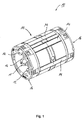
- the Fig. 1 shows by way of illustration a perspective view of a designed as a linear ball bearing 10 conventional linear guide.
- the conventional linear guide 10 includes one in the Fig. 1 not shown shaft as an inner guide member, and a sleeve surrounding the shaft cylindrical 11, which is also referred to below as a cage.
- the bush or the cage 11 in turn comprises a plurality of endless Wälz stresses- or ball circuits 12.
- An endless ball circulation 12 is formed by a ball channel, which can be divided into a flow or load / support channel and a return channel. In the flow channel is in each case one (during operation) currently bearing ball row, ie those balls 13 which support the cylindrical cage 11 relative to the shaft.
- the balls 13 located in the feed channel roll between a raceway formed by the shaft surface and a mating track 14 located on the side of the cage or the bush 11.
- bearing assembly 10 are housed in end rings 16, the balls 13 can be deflected from the flow channel into a corresponding load-free return passage of the cage 11 be, and vice versa. This results in an endless recirculating ball in the ball guide channel 12.
- the bearing assembly 10 can be sealed by means of seals located on the end rings 16 against an external environment.
- In the deflecting or closing rings 16 can also be lubricant deposits for lubrication of the rolling elements 13.
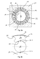
- the Fig. 2a shows a cross-sectional view of the linear guide assembly 10 according to Fig. 1 , which is installed in a housing 21.
- a total of six ball guide channels 22 can be seen, each of which in turn can be divided into flow and support channels 23 and return channels 24.
- the rolling elements or balls 13 roll between roller tracks 25, which are formed by the shaft surface of the shaft 26, and mating tracks 27 from.
- the mating tracks 27 are formed by fitted into the cage 11 track pieces or inserts 14, which may be made of hardened steel, for example.
- the guided in the flow channel 23 rolling elements 13 are by means of the basis of Fig. 1 deflecting regions 15 described deflected in a corresponding return channel 24, in which they are returned unloaded during operation of the linear guide 10, in turn, then enter the flow channel 23.
- the Fig. 2b shows an enlarged cross-sectional view of a ball feed channel 23, in which a ball 13 rolls between the shaft 26 and the raceway 14 inserted into the cage 11.
- the cylindrical cage 11 is located together with the track pieces 14 in a housing bore of the bearing housing 21.
- a cylindrical inner surface of the housing bore is in the Fig. 2b provided with the reference numeral 28.
- the career or the run web piece 14 has a circumferential balls 13 facing and concave shaped raceway surface 29.
- the concave or curved raceway surface 29 extends conventionally in cross-section arcuate, ie round.
- a curvature of the raceway surface 29 is less pronounced than a curvature of the spherical surface of the ball 13, which rolls between the raceway surface 29 and the surface of the shaft 26. Due to the lower curvature of the raceway surface 29 in comparison to the ball surface, two defined contact points between the ball 13, the shaft surface and the ball-facing raceway surface 29 result in the loaded state.
- the two defined contact points in the flow channel 23 are denoted by the reference numerals 30-1 and 30 -2 provided.
- one of the housing bore facing, radially outer surface 31 of the raceway 14 is adapted in its contour of the surface 28 of the housing bore.
- a curvature of the radially outer surface 31 of the track is equal to a curvature of the cylindrical housing bore.
- This predefined 2-point contact between ball and raceway (or 3-point contact, if the shaft is also taken into account) can increase the load capacity of the linear bearing or the linear guide.
- exemplary embodiments provide a correspondingly designed raceway for a linear guide.
- the linear guide comprises an inner guide part in the form of a shaft and an outer guide part comprising a cage.
- the outer and inner guide parts, d. H. that is, the cage and the shaft are movable relative to each other in the direction of the shaft axis by means of circulating balls in the cage.
- the track of the Linearfiihrung has a (in operation) rotating balls facing raceway surface on which the balls between the raceway surface and a surface of the shaft can roll during operation of the linear guide.
- the ball facing (ie, radially inner) raceway surface is formed such that on the raceway surface for a rolling off between the raceway surface and the shaft surface ball two predefined and circumferentially spaced ball contact areas or points are provided, where the Unroll ball.
- Predefined here means that the two contact areas do not arise randomly during operation, but that they are deliberately formed beforehand as predetermined contact areas or surfaces for circulating balls.
- the radially inner raceway surface is shaped such that exactly two predefined contact areas or points for the revolving balls are provided by their geometry during operation of the linear guide. Together with a contact point for a rotating ball on the shaft then arise for the ball then exactly three contact points in the ball supply passage during the ball circulation.
- This 3-point contact in the flow channel during operation between a rotating ball, the shaft and the mating track in the cage has a positive effect on a load rating of the linear guide.
- embodiments of the present invention can thus increase load ratings of linear ball bearings.
- the raceway surface of the (counter) track facing the balls which rotate during operation is substantially concave. That is, the raceway surface is curved so as to partially encircle a circumferential ball in the circumferential direction to guide it.
- Concavely curved includes, in cross-section perpendicular to the shaft axis, also straight-lined raceway surface portions.
- the raceway surface may have raceway surface portions protruding and recessed backward in a radial direction toward the ball, the two predefined contact areas of the raceway surface being formed by raceway surface portions at least partially projecting and circumferentially spaced from one another.
- Embodiments of the present invention include various track geometries that provide protruding and recessed track surface sections, respectively.
- the track in a plane perpendicular to an axial extent (corresponding to the longitudinal axis) of the linear guide or the raceway a polygonal cross-section, such as. B. have a partially polygonal cross-section.
- the concave raceway surface is in accordance with The embodiments not round but polygonal running with flat raceway surface sections.
- Some examples see z. B. three flat and parallel to the longitudinal direction of the track extending track surface sections, of which two flat Laufbahnobervidabexcellente the rotating balls tangential.D. That is, the two raceway surface sections, which include the two predefined contact areas are tangential surface portions which tangent to the spherical surface of a circulating in operation Ball run.
- the raceway surface facing the balls may have a substantially circular cross-section in a plane perpendicular to the axial extent of the raceway, with projections arranged circumferentially along the raceway surface at predefined intervals and serving as contact areas, radially inwardly facing projections.
- the two projecting raceway surface portions, i. H. the protrusions serving as the two contact surfaces are convex, for example, whereas the other recessed raceway surface portions may be concavely curved.
- the exactly two predefined and in the circumferential direction of the ball spaced contact areas or contact surfaces of the raceway surface are preferably arranged symmetrically to a running in the radial direction axis of symmetry of the track or a rolling ball on the track.
- a track according to the invention is used in particular for linear ball guides, in which the outer guide member or the cage is formed as a cylindrical sleeve which can be received by a cylindrical housing bore.
- the (counter) track can be inserted into the cylindrical bushing or the cage in such a way that the raceway surface facing the revolving balls points radially into the interior of the cage, that is to say in the direction of the shaft.
- One of the housing bore facing, ie radially outwardly facing surface of the track has, according to embodiments, a greater curvature than the housing bore.
- Exemplary embodiments therefore provide a track for a linear guide with an inner guide part formed as a shaft and a cage designed as a cylindrical bushing as the outer guide part.
- the cage is movable relative to the shaft by means of circulating balls in the cage.
- the cylindrical bushing or cage can be received by a cylindrical bearing housing bore.
- the raceway can be inserted into the cage formed by the cylindrical bushing such that a raceway surface facing the revolving balls, on which the balls can roll between the raceway and a surface of the shaft, points radially inward of the bushing.
- the track is designed such that two predefined contact areas which are spaced apart from one another in the circumferential direction of the ball are provided on the raceway surface facing the revolving balls (radially inner raceway surface) for a ball rolling between the track surface and the surface of the shaft can.
- one of the bearing housing bore facing (radially outer) raceway surface has a greater curvature than the cylindrical bearing housing bore, so that forms a linear contact area between the raceway and the bearing housing bore when inserting the cylindrical sleeve with the raceway inserted therein in the bearing housing bore.
- a line-shaped contact area between the outer raceway side and the housing bore can form during the introduction of the cylindrical bushing with the raceway into the housing bore.
- this in turn means a defined contact point between the raceway outside and housing bore.
- the curvature of the tread outside can be adapted to a smallest bearing size, and thus to a smallest housing diameter.
- For larger housing diameter then results when inserting the cage along with career described one-point or one-line contact between the raceway outside and housing bore. This allows for easier measuring of the track thickness and more reliable automation in an assembly machine.
- An influence of track thickness variations in the same ball sorting and an influence on the desired operating clearance can be minimized by embodiments.
- a linear guide is proposed with a cage designed as a cylindrical bush, in which at least one inventive track is used, wherein the cage with the at least one used or recorded raceway is mounted in the cylindrical bearing housing bore.
- the cage is thus installed in the housing bore, ie, is in the installed state.
- a stable 3-point position for a revolving ball results during operation of the ball guides.
- a stable 3-point position for the career Due to the proposed two-point contact between the ball and raceway a load rating can be increased, which in turn can result in longer lifetimes, especially for longer strokes of linear guides.
- load ratings allow embodiments lower hardness of the raceway material, resulting in a larger selection of base materials such. As drawing steels, results for careers. Softer base materials in turn allow easier processing of the raceway profiles, z. B. a processing of the inlet contour.
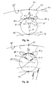
- the Fig. 3a shows an enlarged cross-sectional view of a flow channel of a linear guide according to the invention (linear ball bearing), wherein a ball 13 between a shaft 26 and a (counter) track 34 of the linear guide is guided.
- a cage which receives the (counter) track 34, not shown.
- the raceway 34 has a raceway surface 35 (ie radially inward) facing the revolving ball 13, on which the ball 13 can roll between the raceway surface 35 and a shaft surface 36 during operation of the linear guide.
- raceway surface 35 is formed such that on the raceway surface 35 for a rolling off between the raceway surface 35 and the shaft surface 36 ball 13 two predefined and circumferentially 37 of the ball spaced contact areas and points 38-1 and 38-2 are provided, on which the ball 13 can roll in the axial direction.
- An exact location of the contact points 38-1 and 38-2 is determined by the geometry of the raceway surface 35 and the ball diameter.
- the two predefined contact areas 38-1 and 38-2 are predefined contact points of the ball 13 with the raceway surface 35.
- these contact points 38-1 and 38 travel with the ball along the track 34 -2 each one substantially straight Line on the raceway surface 35 along the longitudinal or extension direction of the raceway 34.
- the raceway surface 35 in a plane perpendicular to the axial extent of the track 34 has a polygonal, in particular partially polygonal cross-section.
- the raceway surface 35 in the illustrated form has three planar raceway surface sections 35-1, 35-2 and 35-3, all of which are arranged parallel to the longitudinal axis or extension direction of the raceway 34 (into the plane of the drawing).
- the raceway surface 35 may thus according to some embodiments in a plane perpendicular to an axial extent of the track 34 have a polygonal, in particular partially polygonal, cross-section, so that the two contact portions 38-1, 38-2 by parallel to a longitudinal axis of the track 34 polygonal arranged, planar raceway surface portions 35-1 and 35-3 are formed.
- the tread 35 may thus be formed as a symmetrical polygonal channel with flat boundary surfaces 35-1, 35-2 and 35-3, two of which (35-1 and 35-3) provide the contact points 38-1 and 38-2.
- the three raceway surface sections 35-1 to 35-3 are arranged in an axisymmetric manner with respect to a radially extending symmetry axis 39 through the ball 13 or the raceway 34. While the middle surface portion 35-2 extends substantially perpendicular to the axis of symmetry 39, the two outer planar raceway surface portions 35-1 and 35-3 are disposed obliquely therewith, comparable to legs of an isosceles triangle.
- the two planar and sloping raceway surface portions 35-1 and 35-3 may, according to some embodiments, form tangential surface portions for the ball 13 encircling the race 34, the tangential surface portions 35-1 and 35-3 tangent to the spherical surface in the loaded condition of the bearing. More generally, therefore, the raceway surface 35 has (at least partially) projecting raceway surface portions 35-1 and 35-3 in a radial direction facing the ball 13 and a raceway surface portion 35-2 radially recessed.
- the two predefined contact areas 38-1 and 38-2 are formed by the raceway surface portions 35-1 and 35-3 projecting in the radial direction opposite to the tread portion 35-2 and circumferentially spaced from each other.
- Connecting lines 40-1 and 40-3 between a center of the revolving ball 13 and the contact points 38-1 and 38-2 close with the axis of symmetry 39 each have an angle ⁇ .
- the angle ⁇ depends, in addition to an inclination angle ⁇ of the two inclined tread portions 35-1, 35-3 with respect to the axis of symmetry 39, from an available space for the linear guide or a diameter of the rotating balls 13.
- Embodiments of the present invention provide geometries in which the angle ⁇ is preferably in a range of 20 ° to 45 °.
- the angle ⁇ is preferably in a range of 20 ° to 45 °.
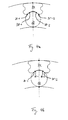
- the raceway surface 35 may also be substantially circular in a plane perpendicular to the axial extent of the raceway 34, with projections arranged circumferentially 37 along the raceway surface at predefined intervals and serving as contact areas in the direction of ball 13 (see FIG Fig. 4a ).
- the projecting raceway surface portions ie the projections, which serve as contact surfaces, for example, may be convex, whereas the other recessed raceway surface portions may be cylindrically shaped or concave (in FIG Fig. 4a not shown).
- prismatic contact surfaces 35-1, 35-3 instead of in the Fig. 3a shown straight, prismatic contact surfaces 35-1, 35-3 also a so-called gothic (ogival) profile can be used to allow a further increase in the load ratings (see Fig. 4b ).
- the raceway 34 On a radially outwardly facing side, the raceway 34 has an outer raceway surface 42 which is more curved than the surface 28 of the cylindrical housing bore. Due to these different degrees of curvature of the surfaces 42nd and 28 also results in a defined contact point 43 between the track 34 and the housing bore in cross section. "Curvature” is to be understood in the context of the present invention, a measure of the deviation of a surface of a tangent through the contact point 43. That is, as viewed in the circumferential direction 44 of the housing bore, soft spots on the outer raceway surface 42 are more distinct from the tangent through the point 43 than points on the housing bore surface 28. That is, a circle defining the outer raceway surface 42.
- the curvatures of the two surfaces 28 and 42 preferably do not differ by more than 40%.
- the curvature k B of the housing bore surface 28 deviates by no more than 40% from the curvature k L of the outer raceway surface 42, ie 0.6 k L ⁇ k B ⁇ k L or k B ⁇ k L ⁇ 1.4 k B.
- a difference of the two curvatures may be in a range below 20%. It is important that the two curvatures differ, not only because of manufacturing tolerances. That is, a difference of the two curvatures (starting from k B or k L ) should be at least 5%, preferably at least 10% and more preferably at least 15%.
- the hatched area 51 shows a curvature area in which the curvature k L of the upper raceway surface 42 should lie, so that the construction and its function remain stable.
- a raceway opening angle ⁇ depends on several factors, but mainly on the size of the linear bearing, ie, the size of the ball 13, width of the raceway 34, etc.
- the raceway opening angle ⁇ indirectly influences the raceway radius R L. The smaller the raceway opening angle ⁇ becomes, the smaller becomes a minimum raceway radius R L, min .
- a width b of the track 34 is crucial for the stable 2-point contact between ball 13 and track 34.
- the width of the extension of the stable zone 51 is limited by means of the outermost contact point of the ball 13 in the prism formed by the raceway surface 35.
- the minimum track radius R L, min can be defined by a height h, which in turn is the distance from the center of the ball and the contact point 43 of the track 34 to the housing bore. Only if h1 (ie the track radius R L ) is greater than h, the construction will always aim for a stable position. This means that the track radius R L , which defines the curvature k L , should lie between a radius R G of the housing bore and the distance h from the center of the sphere and to the contact point 43.
- Center points of arcs with the different radii are all on the axis 39. This allows the track 34 center itself, regardless of the radius R w of the shaft 26 and the radius R G of the bearing housing, as long as these two have a common origin. This is always the case. Even if both radii R w and R G should be infinite. In other words, a radial height h1 of the raceway 34 in the direction "hx" from the middle of the raceway should always be greater than h. Then theoretically, the angle career opening angle ⁇ can be up to 180 °.
- the construction remains stable and will center itself when in the entire system of linear bearings in the housing on a shaft with at least three raceways 34 (see Fig. 5b ) arise due to operating loads certain elastic deformations.
- the Fig. 3b shows the use of a track 34 according to the invention for different sized shaft diameter D1 and D2, which lead at the same housing bore to different sized ball diameters d1 and d2.
- the position of the contact point 43 does not change, so that in both cases the same track 34, but with different balls, can be used as long as the ball always two contact points 38-1, 38-2 with the Track has and the outer curvature of the track 34 still produces a line contact with the housing bore.
- aspects have been described in the context of a device or a linear guide, it is understood that these aspects also represent a description of a corresponding method, in particular an operating or manufacturing method, so that a block or a component of a device as a corresponding Process step or as a feature of a process step, for example, for the production or operation of a linear guide to understand.
- aspects described in connection with or as a method step also represent a description of a corresponding block or detail or feature of a corresponding device.
Landscapes
- Engineering & Computer Science (AREA)
- General Engineering & Computer Science (AREA)
- Mechanical Engineering (AREA)
- Bearings For Parts Moving Linearly (AREA)
Applications Claiming Priority (2)
| Application Number | Priority Date | Filing Date | Title |
|---|---|---|---|
| DE201210206373 DE102012206373A1 (de) | 2012-04-18 | 2012-04-18 | Laufbahn mit definierten Kontaktbereichen |
| DE201220101437 DE202012101437U1 (de) | 2012-04-18 | 2012-04-18 | Laufbahn mit definierten Kontaktbereichen |
Publications (3)
| Publication Number | Publication Date |
|---|---|
| EP2653737A2 true EP2653737A2 (fr) | 2013-10-23 |
| EP2653737A3 EP2653737A3 (fr) | 2017-09-27 |
| EP2653737B1 EP2653737B1 (fr) | 2023-08-30 |
Family
ID=48190111
Family Applications (1)
| Application Number | Title | Priority Date | Filing Date |
|---|---|---|---|
| EP13164335.5A Active EP2653737B1 (fr) | 2012-04-18 | 2013-04-18 | Chemin de roulement dotée de zones de contact définies |
Country Status (1)
| Country | Link |
|---|---|
| EP (1) | EP2653737B1 (fr) |
Cited By (1)
| Publication number | Priority date | Publication date | Assignee | Title |
|---|---|---|---|---|
| FR3053417A1 (fr) * | 2016-06-30 | 2018-01-05 | Aktiebolaget Skf | Cage de palier lineaire |
Family Cites Families (7)
| Publication number | Priority date | Publication date | Assignee | Title |
|---|---|---|---|---|
| DE2849758C2 (de) * | 1978-11-16 | 1982-08-05 | Deutsche Star Kugelhalter Gmbh, 8720 Schweinfurt | Drehmomentübertragende, axial verschiebbare Lagerung einer Welle |
| GB2104162B (en) * | 1981-08-17 | 1985-06-26 | Skf Kugellagerfabriken Gmbh | A shaft and a housing mounted for longtitudinal movement relative to each other and torque transmission by a linear bearing |
| US4952075A (en) * | 1989-05-26 | 1990-08-28 | Thomson Industries, Inc. | Linear motion ball bearing assembly |
| DE10249975B4 (de) * | 2002-10-26 | 2009-06-10 | Ab Skf | Führungsschiene für ein Linearlager |
| DE102006052597B4 (de) * | 2006-11-08 | 2019-03-07 | AMK Arnold Müller GmbH & Co. KG | Linearwälzlager |
| DE102006060609A1 (de) * | 2006-12-21 | 2008-06-26 | AMK Arnold Müller GmbH & Co. KG | Lineares Wälzlagerelement |
| DE102008039848B4 (de) * | 2008-08-27 | 2015-03-26 | Ab Skf | Wälzlager für Längsbewegungen |
-
2013
- 2013-04-18 EP EP13164335.5A patent/EP2653737B1/fr active Active
Non-Patent Citations (1)
| Title |
|---|
| None |
Cited By (1)
| Publication number | Priority date | Publication date | Assignee | Title |
|---|---|---|---|---|
| FR3053417A1 (fr) * | 2016-06-30 | 2018-01-05 | Aktiebolaget Skf | Cage de palier lineaire |
Also Published As
| Publication number | Publication date |
|---|---|
| EP2653737A3 (fr) | 2017-09-27 |
| EP2653737B1 (fr) | 2023-08-30 |
Similar Documents
| Publication | Publication Date | Title |
|---|---|---|
| EP2507523B1 (fr) | Agencement de roulement à billes | |
| DE102011004374A1 (de) | Lagerkäfigsegment, Lagerkäfig und Verfahren zur Herstellung desselben | |
| DE102016214347B3 (de) | Verfahren und Vorrichtung zur Montage eines Schrägrollenlagers | |
| DE4015303C2 (fr) | ||
| DE102015224859A1 (de) | Kugellagerkäfig | |
| WO2007065414A1 (fr) | Roulement radial, en particulier roulement rainure a une rangee | |
| WO2011018491A1 (fr) | Segment de cage pour une cage en plastique de palier à roulement et palier à roulement pourvu d'un tel segment | |
| DE102016211906A1 (de) | Käfig für Kurbelwellenlagerung | |
| DE212015000042U1 (de) | Kugelgewindetrieb | |
| WO2000008344A1 (fr) | Chariot de dispositif de guidage lineaire | |
| DE102016125258A1 (de) | Wälzlager | |
| EP2210831A1 (fr) | Dispositif de transport et élément de transport | |
| EP3810944B1 (fr) | Butée axiale a roulement | |
| DE102021129190A1 (de) | Lagerkäfig für Zylinderrollen und Zylinderrollenlager mit einem solchen Lagerkäfig | |
| DE102009032699A1 (de) | Rollenlagerwälzkörper | |
| EP2653737B1 (fr) | Chemin de roulement dotée de zones de contact définies | |
| DE102012206373A1 (de) | Laufbahn mit definierten Kontaktbereichen | |
| DE202012101437U1 (de) | Laufbahn mit definierten Kontaktbereichen | |
| WO2010072197A1 (fr) | Cage à segments | |
| EP2789867B1 (fr) | Canal de guidage à billes d'un guidage linéaire à palier à billes | |
| DE10002818A1 (de) | Linearführungsvorrichtung | |
| DE102006059186A1 (de) | Einstelllager | |
| DE2922625A1 (de) | Waelzlager fuer laengsbewegungen | |
| DE102021126238B4 (de) | Schrägkugellager | |
| DE102014212075B4 (de) | Lagerkäfig für ein Kegelrollenlager |
Legal Events
| Date | Code | Title | Description |
|---|---|---|---|
| PUAI | Public reference made under article 153(3) epc to a published international application that has entered the european phase |
Free format text: ORIGINAL CODE: 0009012 |
|
| AK | Designated contracting states |
Kind code of ref document: A2 Designated state(s): AL AT BE BG CH CY CZ DE DK EE ES FI FR GB GR HR HU IE IS IT LI LT LU LV MC MK MT NL NO PL PT RO RS SE SI SK SM TR |
|
| AX | Request for extension of the european patent |
Extension state: BA ME |
|
| PUAL | Search report despatched |
Free format text: ORIGINAL CODE: 0009013 |
|
| AK | Designated contracting states |
Kind code of ref document: A3 Designated state(s): AL AT BE BG CH CY CZ DE DK EE ES FI FR GB GR HR HU IE IS IT LI LT LU LV MC MK MT NL NO PL PT RO RS SE SI SK SM TR |
|
| AX | Request for extension of the european patent |
Extension state: BA ME |
|
| RIC1 | Information provided on ipc code assigned before grant |
Ipc: F16C 29/06 20060101AFI20170823BHEP Ipc: F16C 33/58 20060101ALI20170823BHEP |
|
| STAA | Information on the status of an ep patent application or granted ep patent |
Free format text: STATUS: REQUEST FOR EXAMINATION WAS MADE |
|
| 17P | Request for examination filed |
Effective date: 20171220 |
|
| RBV | Designated contracting states (corrected) |
Designated state(s): AL AT BE BG CH CY CZ DE DK EE ES FI FR GB GR HR HU IE IS IT LI LT LU LV MC MK MT NL NO PL PT RO RS SE SI SK SM TR |
|
| RAP1 | Party data changed (applicant data changed or rights of an application transferred) |
Owner name: EWELLIX AB |
|
| STAA | Information on the status of an ep patent application or granted ep patent |
Free format text: STATUS: EXAMINATION IS IN PROGRESS |
|
| 17Q | First examination report despatched |
Effective date: 20210602 |
|
| RAP3 | Party data changed (applicant data changed or rights of an application transferred) |
Owner name: EWELLIX AB |
|
| GRAP | Despatch of communication of intention to grant a patent |
Free format text: ORIGINAL CODE: EPIDOSNIGR1 |
|
| STAA | Information on the status of an ep patent application or granted ep patent |
Free format text: STATUS: GRANT OF PATENT IS INTENDED |
|
| GRAJ | Information related to disapproval of communication of intention to grant by the applicant or resumption of examination proceedings by the epo deleted |
Free format text: ORIGINAL CODE: EPIDOSDIGR1 |
|
| STAA | Information on the status of an ep patent application or granted ep patent |
Free format text: STATUS: EXAMINATION IS IN PROGRESS |
|
| INTG | Intention to grant announced |
Effective date: 20230214 |
|
| INTC | Intention to grant announced (deleted) | ||
| GRAP | Despatch of communication of intention to grant a patent |
Free format text: ORIGINAL CODE: EPIDOSNIGR1 |
|
| STAA | Information on the status of an ep patent application or granted ep patent |
Free format text: STATUS: GRANT OF PATENT IS INTENDED |
|
| INTG | Intention to grant announced |
Effective date: 20230511 |
|
| P01 | Opt-out of the competence of the unified patent court (upc) registered |
Effective date: 20230514 |
|
| GRAS | Grant fee paid |
Free format text: ORIGINAL CODE: EPIDOSNIGR3 |
|
| GRAA | (expected) grant |
Free format text: ORIGINAL CODE: 0009210 |
|
| STAA | Information on the status of an ep patent application or granted ep patent |
Free format text: STATUS: THE PATENT HAS BEEN GRANTED |
|
| AK | Designated contracting states |
Kind code of ref document: B1 Designated state(s): AL AT BE BG CH CY CZ DE DK EE ES FI FR GB GR HR HU IE IS IT LI LT LU LV MC MK MT NL NO PL PT RO RS SE SI SK SM TR |
|
| REG | Reference to a national code |
Ref country code: GB Ref legal event code: FG4D Free format text: NOT ENGLISH |
|
| REG | Reference to a national code |
Ref country code: CH Ref legal event code: EP |
|
| REG | Reference to a national code |
Ref country code: DE Ref legal event code: R096 Ref document number: 502013016450 Country of ref document: DE |
|
| REG | Reference to a national code |
Ref country code: IE Ref legal event code: FG4D Free format text: LANGUAGE OF EP DOCUMENT: GERMAN |
|
| REG | Reference to a national code |
Ref country code: LT Ref legal event code: MG9D |
|
| REG | Reference to a national code |
Ref country code: NL Ref legal event code: MP Effective date: 20230830 |
|
| PG25 | Lapsed in a contracting state [announced via postgrant information from national office to epo] |
Ref country code: GR Free format text: LAPSE BECAUSE OF FAILURE TO SUBMIT A TRANSLATION OF THE DESCRIPTION OR TO PAY THE FEE WITHIN THE PRESCRIBED TIME-LIMIT Effective date: 20231201 |
|
| PG25 | Lapsed in a contracting state [announced via postgrant information from national office to epo] |
Ref country code: IS Free format text: LAPSE BECAUSE OF FAILURE TO SUBMIT A TRANSLATION OF THE DESCRIPTION OR TO PAY THE FEE WITHIN THE PRESCRIBED TIME-LIMIT Effective date: 20231230 |
|
| PG25 | Lapsed in a contracting state [announced via postgrant information from national office to epo] |
Ref country code: SE Free format text: LAPSE BECAUSE OF FAILURE TO SUBMIT A TRANSLATION OF THE DESCRIPTION OR TO PAY THE FEE WITHIN THE PRESCRIBED TIME-LIMIT Effective date: 20230830 Ref country code: RS Free format text: LAPSE BECAUSE OF FAILURE TO SUBMIT A TRANSLATION OF THE DESCRIPTION OR TO PAY THE FEE WITHIN THE PRESCRIBED TIME-LIMIT Effective date: 20230830 Ref country code: NO Free format text: LAPSE BECAUSE OF FAILURE TO SUBMIT A TRANSLATION OF THE DESCRIPTION OR TO PAY THE FEE WITHIN THE PRESCRIBED TIME-LIMIT Effective date: 20231130 Ref country code: LV Free format text: LAPSE BECAUSE OF FAILURE TO SUBMIT A TRANSLATION OF THE DESCRIPTION OR TO PAY THE FEE WITHIN THE PRESCRIBED TIME-LIMIT Effective date: 20230830 Ref country code: LT Free format text: LAPSE BECAUSE OF FAILURE TO SUBMIT A TRANSLATION OF THE DESCRIPTION OR TO PAY THE FEE WITHIN THE PRESCRIBED TIME-LIMIT Effective date: 20230830 Ref country code: IS Free format text: LAPSE BECAUSE OF FAILURE TO SUBMIT A TRANSLATION OF THE DESCRIPTION OR TO PAY THE FEE WITHIN THE PRESCRIBED TIME-LIMIT Effective date: 20231230 Ref country code: HR Free format text: LAPSE BECAUSE OF FAILURE TO SUBMIT A TRANSLATION OF THE DESCRIPTION OR TO PAY THE FEE WITHIN THE PRESCRIBED TIME-LIMIT Effective date: 20230830 Ref country code: GR Free format text: LAPSE BECAUSE OF FAILURE TO SUBMIT A TRANSLATION OF THE DESCRIPTION OR TO PAY THE FEE WITHIN THE PRESCRIBED TIME-LIMIT Effective date: 20231201 Ref country code: FI Free format text: LAPSE BECAUSE OF FAILURE TO SUBMIT A TRANSLATION OF THE DESCRIPTION OR TO PAY THE FEE WITHIN THE PRESCRIBED TIME-LIMIT Effective date: 20230830 |
|
| PG25 | Lapsed in a contracting state [announced via postgrant information from national office to epo] |
Ref country code: PL Free format text: LAPSE BECAUSE OF FAILURE TO SUBMIT A TRANSLATION OF THE DESCRIPTION OR TO PAY THE FEE WITHIN THE PRESCRIBED TIME-LIMIT Effective date: 20230830 Ref country code: NL Free format text: LAPSE BECAUSE OF FAILURE TO SUBMIT A TRANSLATION OF THE DESCRIPTION OR TO PAY THE FEE WITHIN THE PRESCRIBED TIME-LIMIT Effective date: 20230830 |
|
| PG25 | Lapsed in a contracting state [announced via postgrant information from national office to epo] |
Ref country code: ES Free format text: LAPSE BECAUSE OF FAILURE TO SUBMIT A TRANSLATION OF THE DESCRIPTION OR TO PAY THE FEE WITHIN THE PRESCRIBED TIME-LIMIT Effective date: 20230830 |
|
| PG25 | Lapsed in a contracting state [announced via postgrant information from national office to epo] |
Ref country code: SM Free format text: LAPSE BECAUSE OF FAILURE TO SUBMIT A TRANSLATION OF THE DESCRIPTION OR TO PAY THE FEE WITHIN THE PRESCRIBED TIME-LIMIT Effective date: 20230830 Ref country code: RO Free format text: LAPSE BECAUSE OF FAILURE TO SUBMIT A TRANSLATION OF THE DESCRIPTION OR TO PAY THE FEE WITHIN THE PRESCRIBED TIME-LIMIT Effective date: 20230830 Ref country code: ES Free format text: LAPSE BECAUSE OF FAILURE TO SUBMIT A TRANSLATION OF THE DESCRIPTION OR TO PAY THE FEE WITHIN THE PRESCRIBED TIME-LIMIT Effective date: 20230830 Ref country code: EE Free format text: LAPSE BECAUSE OF FAILURE TO SUBMIT A TRANSLATION OF THE DESCRIPTION OR TO PAY THE FEE WITHIN THE PRESCRIBED TIME-LIMIT Effective date: 20230830 Ref country code: DK Free format text: LAPSE BECAUSE OF FAILURE TO SUBMIT A TRANSLATION OF THE DESCRIPTION OR TO PAY THE FEE WITHIN THE PRESCRIBED TIME-LIMIT Effective date: 20230830 Ref country code: CZ Free format text: LAPSE BECAUSE OF FAILURE TO SUBMIT A TRANSLATION OF THE DESCRIPTION OR TO PAY THE FEE WITHIN THE PRESCRIBED TIME-LIMIT Effective date: 20230830 Ref country code: SK Free format text: LAPSE BECAUSE OF FAILURE TO SUBMIT A TRANSLATION OF THE DESCRIPTION OR TO PAY THE FEE WITHIN THE PRESCRIBED TIME-LIMIT Effective date: 20230830 Ref country code: PT Free format text: LAPSE BECAUSE OF FAILURE TO SUBMIT A TRANSLATION OF THE DESCRIPTION OR TO PAY THE FEE WITHIN THE PRESCRIBED TIME-LIMIT Effective date: 20240102 |
|
| PG25 | Lapsed in a contracting state [announced via postgrant information from national office to epo] |
Ref country code: IT Free format text: LAPSE BECAUSE OF FAILURE TO SUBMIT A TRANSLATION OF THE DESCRIPTION OR TO PAY THE FEE WITHIN THE PRESCRIBED TIME-LIMIT Effective date: 20230830 |
|
| REG | Reference to a national code |
Ref country code: DE Ref legal event code: R097 Ref document number: 502013016450 Country of ref document: DE |
|
| REG | Reference to a national code |
Ref country code: DE Ref legal event code: R081 Ref document number: 502013016450 Country of ref document: DE Owner name: SCHAEFFLER TECHNOLOGIES AG & CO. KG, DE Free format text: FORMER OWNER: EWELLIX AB, PARTILLE, GOETEBORG, SE Ref legal event code: R082 Ref document number: 502013016450 Country of ref document: DE Ref country code: DE Ref legal event code: R082 Ref document number: 502013016450 Country of ref document: DE Representative=s name: HEYERHOFF GEIGER GMBH & CO. KG, DE |
|
| PLBE | No opposition filed within time limit |
Free format text: ORIGINAL CODE: 0009261 |
|
| STAA | Information on the status of an ep patent application or granted ep patent |
Free format text: STATUS: NO OPPOSITION FILED WITHIN TIME LIMIT |
|
| PG25 | Lapsed in a contracting state [announced via postgrant information from national office to epo] |
Ref country code: SI Free format text: LAPSE BECAUSE OF FAILURE TO SUBMIT A TRANSLATION OF THE DESCRIPTION OR TO PAY THE FEE WITHIN THE PRESCRIBED TIME-LIMIT Effective date: 20230830 |
|
| 26N | No opposition filed |
Effective date: 20240603 |
|
| PG25 | Lapsed in a contracting state [announced via postgrant information from national office to epo] |
Ref country code: BG Free format text: LAPSE BECAUSE OF FAILURE TO SUBMIT A TRANSLATION OF THE DESCRIPTION OR TO PAY THE FEE WITHIN THE PRESCRIBED TIME-LIMIT Effective date: 20230830 |
|
| PG25 | Lapsed in a contracting state [announced via postgrant information from national office to epo] |
Ref country code: MC Free format text: LAPSE BECAUSE OF FAILURE TO SUBMIT A TRANSLATION OF THE DESCRIPTION OR TO PAY THE FEE WITHIN THE PRESCRIBED TIME-LIMIT Effective date: 20230830 |
|
| PG25 | Lapsed in a contracting state [announced via postgrant information from national office to epo] |
Ref country code: MC Free format text: LAPSE BECAUSE OF FAILURE TO SUBMIT A TRANSLATION OF THE DESCRIPTION OR TO PAY THE FEE WITHIN THE PRESCRIBED TIME-LIMIT Effective date: 20230830 Ref country code: BG Free format text: LAPSE BECAUSE OF FAILURE TO SUBMIT A TRANSLATION OF THE DESCRIPTION OR TO PAY THE FEE WITHIN THE PRESCRIBED TIME-LIMIT Effective date: 20230830 |
|
| REG | Reference to a national code |
Ref country code: CH Ref legal event code: PL |
|
| PG25 | Lapsed in a contracting state [announced via postgrant information from national office to epo] |
Ref country code: LU Free format text: LAPSE BECAUSE OF NON-PAYMENT OF DUE FEES Effective date: 20240418 |
|
| GBPC | Gb: european patent ceased through non-payment of renewal fee |
Effective date: 20240418 |
|
| REG | Reference to a national code |
Ref country code: BE Ref legal event code: MM Effective date: 20240430 |
|
| PG25 | Lapsed in a contracting state [announced via postgrant information from national office to epo] |
Ref country code: LU Free format text: LAPSE BECAUSE OF NON-PAYMENT OF DUE FEES Effective date: 20240418 |
|
| PG25 | Lapsed in a contracting state [announced via postgrant information from national office to epo] |
Ref country code: BE Free format text: LAPSE BECAUSE OF NON-PAYMENT OF DUE FEES Effective date: 20240430 |
|
| PG25 | Lapsed in a contracting state [announced via postgrant information from national office to epo] |
Ref country code: GB Free format text: LAPSE BECAUSE OF NON-PAYMENT OF DUE FEES Effective date: 20240418 |
|
| PG25 | Lapsed in a contracting state [announced via postgrant information from national office to epo] |
Ref country code: FR Free format text: LAPSE BECAUSE OF NON-PAYMENT OF DUE FEES Effective date: 20240430 |
|
| PG25 | Lapsed in a contracting state [announced via postgrant information from national office to epo] |
Ref country code: GB Free format text: LAPSE BECAUSE OF NON-PAYMENT OF DUE FEES Effective date: 20240418 Ref country code: FR Free format text: LAPSE BECAUSE OF NON-PAYMENT OF DUE FEES Effective date: 20240430 Ref country code: BE Free format text: LAPSE BECAUSE OF NON-PAYMENT OF DUE FEES Effective date: 20240430 Ref country code: CH Free format text: LAPSE BECAUSE OF NON-PAYMENT OF DUE FEES Effective date: 20240430 |
|
| PG25 | Lapsed in a contracting state [announced via postgrant information from national office to epo] |
Ref country code: IE Free format text: LAPSE BECAUSE OF NON-PAYMENT OF DUE FEES Effective date: 20240418 |
|
| REG | Reference to a national code |
Ref country code: DE Ref legal event code: R082 Ref document number: 502013016450 Country of ref document: DE Representative=s name: HEYERHOFF GEIGER GMBH & CO. KG, DE |
|
| REG | Reference to a national code |
Ref country code: AT Ref legal event code: MM01 Ref document number: 1605800 Country of ref document: AT Kind code of ref document: T Effective date: 20240418 |
|
| PGFP | Annual fee paid to national office [announced via postgrant information from national office to epo] |
Ref country code: DE Payment date: 20250618 Year of fee payment: 13 |
|
| PG25 | Lapsed in a contracting state [announced via postgrant information from national office to epo] |
Ref country code: AT Free format text: LAPSE BECAUSE OF NON-PAYMENT OF DUE FEES Effective date: 20240418 |
|
| PG25 | Lapsed in a contracting state [announced via postgrant information from national office to epo] |
Ref country code: CY Free format text: LAPSE BECAUSE OF FAILURE TO SUBMIT A TRANSLATION OF THE DESCRIPTION OR TO PAY THE FEE WITHIN THE PRESCRIBED TIME-LIMIT; INVALID AB INITIO Effective date: 20130418 |
|
| PG25 | Lapsed in a contracting state [announced via postgrant information from national office to epo] |
Ref country code: HU Free format text: LAPSE BECAUSE OF FAILURE TO SUBMIT A TRANSLATION OF THE DESCRIPTION OR TO PAY THE FEE WITHIN THE PRESCRIBED TIME-LIMIT; INVALID AB INITIO Effective date: 20130418 |