EP2653731B1 - Hydraulische Akkumulatoren - Google Patents
Hydraulische Akkumulatoren Download PDFInfo
- Publication number
- EP2653731B1 EP2653731B1 EP13153317.6A EP13153317A EP2653731B1 EP 2653731 B1 EP2653731 B1 EP 2653731B1 EP 13153317 A EP13153317 A EP 13153317A EP 2653731 B1 EP2653731 B1 EP 2653731B1
- Authority
- EP
- European Patent Office
- Prior art keywords
- accumulator
- assembly according
- support member
- responsive
- support
- Prior art date
- Legal status (The legal status is an assumption and is not a legal conclusion. Google has not performed a legal analysis and makes no representation as to the accuracy of the status listed.)
- Active
Links
Images



Classifications
-
- E—FIXED CONSTRUCTIONS
- E21—EARTH OR ROCK DRILLING; MINING
- E21B—EARTH OR ROCK DRILLING; OBTAINING OIL, GAS, WATER, SOLUBLE OR MELTABLE MATERIALS OR A SLURRY OF MINERALS FROM WELLS
- E21B33/00—Sealing or packing boreholes or wells
- E21B33/02—Surface sealing or packing
- E21B33/03—Well heads; Setting-up thereof
- E21B33/035—Well heads; Setting-up thereof specially adapted for underwater installations
- E21B33/0355—Control systems, e.g. hydraulic, pneumatic, electric, acoustic, for submerged well heads
-
- E—FIXED CONSTRUCTIONS
- E21—EARTH OR ROCK DRILLING; MINING
- E21B—EARTH OR ROCK DRILLING; OBTAINING OIL, GAS, WATER, SOLUBLE OR MELTABLE MATERIALS OR A SLURRY OF MINERALS FROM WELLS
- E21B33/00—Sealing or packing boreholes or wells
- E21B33/02—Surface sealing or packing
- E21B33/03—Well heads; Setting-up thereof
- E21B33/06—Blow-out preventers, i.e. apparatus closing around a drill pipe, e.g. annular blow-out preventers
- E21B33/064—Blow-out preventers, i.e. apparatus closing around a drill pipe, e.g. annular blow-out preventers specially adapted for underwater well heads
-
- F—MECHANICAL ENGINEERING; LIGHTING; HEATING; WEAPONS; BLASTING
- F15—FLUID-PRESSURE ACTUATORS; HYDRAULICS OR PNEUMATICS IN GENERAL
- F15B—SYSTEMS ACTING BY MEANS OF FLUIDS IN GENERAL; FLUID-PRESSURE ACTUATORS, e.g. SERVOMOTORS; DETAILS OF FLUID-PRESSURE SYSTEMS, NOT OTHERWISE PROVIDED FOR
- F15B1/00—Installations or systems with accumulators; Supply reservoir or sump assemblies
- F15B1/02—Installations or systems with accumulators
- F15B1/022—Installations or systems with accumulators used as an emergency power source, e.g. in case of pump failure
-
- F—MECHANICAL ENGINEERING; LIGHTING; HEATING; WEAPONS; BLASTING
- F15—FLUID-PRESSURE ACTUATORS; HYDRAULICS OR PNEUMATICS IN GENERAL
- F15B—SYSTEMS ACTING BY MEANS OF FLUIDS IN GENERAL; FLUID-PRESSURE ACTUATORS, e.g. SERVOMOTORS; DETAILS OF FLUID-PRESSURE SYSTEMS, NOT OTHERWISE PROVIDED FOR
- F15B2201/00—Accumulators
- F15B2201/20—Accumulator cushioning means
- F15B2201/205—Accumulator cushioning means using gas
-
- F—MECHANICAL ENGINEERING; LIGHTING; HEATING; WEAPONS; BLASTING
- F15—FLUID-PRESSURE ACTUATORS; HYDRAULICS OR PNEUMATICS IN GENERAL
- F15B—SYSTEMS ACTING BY MEANS OF FLUIDS IN GENERAL; FLUID-PRESSURE ACTUATORS, e.g. SERVOMOTORS; DETAILS OF FLUID-PRESSURE SYSTEMS, NOT OTHERWISE PROVIDED FOR
- F15B2201/00—Accumulators
- F15B2201/50—Monitoring, detection and testing means for accumulators
Definitions
- This invention relates to hydraulic accumulators, in particular one in an underwater (for example subsea) fluid extraction well facility.
- FR2585086 discloses a hydraulic accumulator assembly in which a hydraulic accumulator is associated with at least one means responsive to the weight of the accumulator to provide an indication dependent on the weight of the accumulator.
- WO2012/078048 discloses a hydraulic accumulator assembly according to the precharacterising features of claim 1.
- a hydraulic accumulator assembly in which a hydraulic accumulator in an underwater fluid extraction well facility is provided with at least one means responsive to the weight of the accumulator to provide an indication dependent on the weight of the accumulator.
- the assembly includes support means which support the accumulator, said at least one responsive means being responsive to a force applied to a part of said support means by the weight of the accumulator.
- a cover for the accumulator is carried by said support means, there being a collar at the top of the cover for constraining the accumulator horizontally.
- said support means comprises a first support member to which the accumulator is attached and a second support member for said first support member, said at least one responsive means being responsive to a force between said first and second support members.
- said first support member could be at least partially received by said second support member.
- Such a cover for the accumulator could be carried by said second support member.
- Hydraulic input and output interfaces in said second support member could communicate with passageways in said first support member for supplying fluid to and receiving fluid from the accumulator, and said interfaces could communicate with the said passageways via flexible hoses.
- there could be a single hydraulic input and output in communication with said accumulator for example provided by a flexible hose.
- said support means comprises a support member to which the accumulator is attached and at least one further member attached by attachment means to the support member, said at least one responsive means being responsive to a force applied to said attachment means.
- a cover for the accumulator could be carried by said at least one further member.
- Hydraulic input and output interfaces in said at least one further member could communicate with passageways in said support member for supplying fluid to and receiving fluid from the accumulator, and said interfaces could communicate with said passageways via flexible hoses.
- Said at least one further member could be above said support member in use of the assembly.
- said at least one responsive means typically comprises at least one of a strain gauge, a force gauge, a force meter, a balance scale, a spring force scale, a strain gauge based electronic scale and a fluid-based means of weight measurement.
- an assembly according to the invention is provided with means for receiving and processing data resulting from said indication dependent on the weight of the accumulator.
- the present invention also comprises a method of monitoring the volume of a fluid in a hydraulic accumulator, comprising including the accumulator in an assembly according to the invention and using the at least one responsive means to provide an indication of the weight of the accumulator
- Fig. 1 illustrates an assembly according to a first embodiment of the invention including a hydraulic accumulator 1 in a subsea fluid extraction well facility.
- the assembly is mounted on two support members in the form of plates, namely a larger plate 2 inside which there is a smaller, secondary plate 3.
- the larger plate 2 houses the primary input and output for hydraulic fluid via input and output interfaces 4 and 5 respectively, the second plate 3 being mounted in a recess in the top of the plate 2.
- the accumulator 1 is bolted on to the smaller plate 3 using, typically, a regular flange interface 6.
- the plates 2 and 3 are connected via a means which enables transfer and containment of pressurised hydraulic fluid, but does not constrain the plate 3 in the vertical plane.
- a collar 12 at the top of the cover 11 locates the top of the accumulator 1, preventing it from toppling, but only constraining it in the horizontal plane.
- This configuration provides a marked advantage over prior art assemblies in which the accumulator is constrained horizontally by guide runners arranged laterally to the accumulator, such as the assemblies shown in FR2585086 , as in that configuration a high level of friction occurs due to the moment (rotational force) caused by the accumulator.
- This high level of friction must be overcome with, for example, grease or other lubricants, which are unsuitable for use in the subsea environment for which the present invention is intended, as these may be worn off. Additionally, said runners would be vulnerable to the ingress of foreign debris, particulate matter or marine growth.
- the entire weight of the accumulator and plate 3 on which it is mounted rests on strain gauges 13 which are connected electrically to a logic controller 14, the strain gauges being located between and in engagement with plates 2 and 3.
- the weight of the accumulator 1 will change as the fluid level in it increases or decreases.
- the data received by the logic controller 14 from the strain gauges 13 will enable it to calculate the mass of fluid contained within the accumulator 1.
- Other data required by the logic controller to enable calculation of the available fluid in the accumulator 1 would include the density of the fluid, the pre-charge gas volume / weight, and the weight of the empty accumulator 1 and its plate 3. It may be necessary therefore to calibrate the accumulator 1 with known volumes of pre-charge gas / hydraulic fluid prior to or during initial installation.
- the logic controller 14 could be subsea and in communication with topside equipment or it may itself be located topside.
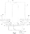
- FIG. 2 A second embodiment of the invention is illustrated in Fig. 2 (in which items which correspond with those in Fig. 1 have the same reference numerals as in Fig. 1 ).
- the hydraulic accumulator 1 is attached to a single support member in the form of a plate 15 which is suspended from an annular mounting plate 16 by attachment means in the form, typically, of four pillars 17.
- a hydraulic input interface 18 is connected to passageway 9 in plate 15 via a flexible, coiled hose 19 and a hydraulic output interface 20 is connected to passageway 10 in plate 15 via a flexible, coiled hose 21.
- the cover 11 is carried by plate 16.
- Strain gauges 22 are attached to respective ones of pillars 17, these strain gauges being connected electrically to logic controller 14, which again could be subsea and in communication with topside equipment or itself be located topside. Preferably, there are at least two strain gauges 22 for reliability and redundancy.
- the weight of the accumulator 1 will change as the fluid level in it increases or decreases and the data received by the logic controller 14 from the strain gauges 22 will enable it to calculate the mass of fluid contained within.
- the input and output hydraulic interfaces 18 and 20 are isolated from the plate 15 by the coiled hoses 19 and 21.
- the configuration of Fig. 2 has the possible slight advantage over that of Fig. 1 in that the strain gauges 22 are not supporting the full mass of the accumulator, and each is measuring the change of strain of a pillar 17, due to the change of weight of the accumulator 1.
- Fig. 3 illustrates a further embodiment of the invention. Items which correspond with those in Fig. 1 have the same reference numerals as in Fig. 1 .
- the hydraulic accumulator 1 is mounted on a pair of support plates, namely a larger plate 2 inside which there is a smaller, secondary plate 3.
- the hydraulic accumulator 1 is again mounted in a sea water flooded cover 11 which is mounted to larger plate 2.
- the hoses 7, 8 and passageways 9, 10 are replaced with a single hydraulic input and output in communication with the accumulator, provided by a single flexible hose 23 that runs, through a seal 24, through the larger plate 2, the smaller plate 3, and into the lower surface of the accumulator 1.
- the arrangement of the strain gauges 13 between the larger plate 2 and smaller plate 3 and the accompanying logic controller 14 are as described with reference to Fig. 1 .
- Fig. 4 illustrates a further embodiment of the invention. Items which correspond with those in Fig. 2 have the same reference numerals as in Fig. 2 .
- the hydraulic accumulator 1 is attached to a single support member in the form of a plate 15 which is attached to an annular mounting plate 16 without the use of pillars.
- hoses 19, 21 and passageways 9,10 are replaced with a single hydraulic input and output in communication with the accumulator, provided by a single flexible hose 25 that runs, through a seal 26, through plate 15, and into the lower surface of the accumulator 1 and the strain gauges 22 are located between and in contact with the mounting plate 16 and plate 15.
- the accumulator is mounted to a fixed plate 2, 16 with the inclusion of at least one strain gauge.
- This provides an improvement over prior art assemblies that use a pivot or spring as the means of compliant mounting, such as the assemblies shown in FR2585086 , as these assemblies may lose their calibration when used in an industrial setting, especially subsea.
- the present invention may use any suitable means of producing an indication dependent on the weight of the accumulator - such as a strain gauge or a force gauge or force meter or a balance scale or a spring force scale or a strain gauge based electronic scale or a fluid (pneumatic or hydraulic) based means of weight measurement or a combination of any of the above.
- Another possible embodiment is one in which the accumulator is on a balance beam assembly connected mechanically to a subsea gauge readable by a diver or a remotely operated vehicle.
- the invention enables an indication of the volume of hydraulic fluid stored in an underwater (for example subsea) accumulator at any given time. Should the indicated volume fall below a set limit, the well master control system can automatically create an alert or warning, which is flagged up to the operator at the topside control centre, that subsea valves may not have sufficient hydraulic fluid accumulated to close as required, i.e. the system would be able to alert an operator of a potentially unsafe condition existing on the well of large, safety critical, tree or manifold or riser post valves. Without this indication the unsafe condition will not be identified.
Landscapes
- Engineering & Computer Science (AREA)
- Life Sciences & Earth Sciences (AREA)
- Geology (AREA)
- Mining & Mineral Resources (AREA)
- Physics & Mathematics (AREA)
- Fluid Mechanics (AREA)
- Environmental & Geological Engineering (AREA)
- General Life Sciences & Earth Sciences (AREA)
- Geochemistry & Mineralogy (AREA)
- Mechanical Engineering (AREA)
- General Engineering & Computer Science (AREA)
- Supply Devices, Intensifiers, Converters, And Telemotors (AREA)
Claims (16)
- Hydraulische Akkumulatoranordnung, bei welcher ein hydraulischer Akkumulator (1) zur Verwendung in einer Unterwasser-Fluidextraktionsquellen-Anlage mit mindestens einem Mittel (13 oder 22) versehen ist, das auf das Gewicht des Akkumulators anspricht, um eine Anzeige in Abhängigkeit von dem Gewicht des Akkumulators zu liefern, wobei die Anordnung Stützmittel (2, 3 oder 15, 16) umfasst, die den Akkumulator stützen, wobei das mindestens eine ansprechende Mittel auf eine Kraft anspricht, die auf einen Teil der Stützmittel durch das Gewicht des Akkumulators ausgeübt wird, wobei die Anordnung durch eine Abdeckung (11) für den Akkumulator gekennzeichnet ist, wobei die Abdeckung von den Stützmitteln getragen wird, und ferner dadurch gekennzeichnet, dass der Akkumulator horizontal durch einen Kragen (12) oben auf der Abdeckung gehalten wird.
- Anordnung nach Anspruch 1, wobei die Stützmittel (2, 3 oder 15, 16) ein erstes Stützelement (3 oder 15), an dem der Akkumulator (1) angebracht ist, und ein zweites Stützelement (2 oder 16) für das erste Stützelement umfassen, wobei das mindestens eine ansprechende Mittel (13 oder 22) auf eine Kraft zwischen dem ersten und zweiten Stützelement anspricht.
- Anordnung nach Anspruch 2, wobei die Abdeckung (11) von dem zweiten Stützmittel (2 oder 16) getragen wird.
- Anordnung nach Anspruch 2 oder 3, wobei das erste Stützelement (3 oder 15) mindestens teilweise von dem zweiten Stützelement (2 oder 16) aufgenommen wird.
- Anordnung nach einem der vorhergehenden Ansprüche, umfassend einen einzelnen hydraulischen Eingang und Ausgang (23 oder 25) in Kommunikation mit dem Akkumulator.
- Anordnung nach einem der Ansprüche 2 bis 4, umfassend hydraulische Eingangs-und Ausgangsschnittstellen (4, 5 oder 18, 20) in dem zweiten Stützelement (2 oder 16), die mit Durchgängen (9, 10) in dem ersten Stützelement (3 oder 15) zum Zuführen von Fluid zu und Empfangen von Fluid von dem Akkumulator (1) kommunizieren.
- Anordnung nach Anspruch 6, wobei die Schnittstellen mit den Durchgängen über flexible Schläuche (7, 8 oder 19, 21) kommunizieren.
- Anordnung nach Anspruch 1, wobei das Stützmittel (2, 3 oder 15, 16) ein Stützelement (3 oder 15), an dem der Akkumulator (1) befestigt ist, und mindestens ein weiteres Element (2 oder 16) umfasst, das durch Befestigungsmittel (17) an dem Stützelement angebracht ist, wobei das mindestens eine ansprechende Mittel (13 oder 22) auf eine Kraft anspricht, die auf die Befestigungsmittel ausgeübt wird.
- Anordnung nach Anspruch 8, wobei die Abdeckung (11) von dem mindestens einen weiteren Element (2 oder 16) getragen wird.
- Anordnung nach Anspruch 8 oder 9, umfassend einen einzelnen hydraulischen Eingang und Ausgang (23 oder 25) in Kommunikation mit dem Akkumulator (1).
- Anordnung nach Anspruch 8 oder 9, umfassend hydraulische Eingangs- und Ausgangsschnittstellen (4, 5 oder 18, 20) in dem mindestens einen weiteren Element (2 oder 16), die mit Durchgängen (9, 10) in dem Stützelement (3 oder 15) zum Zuführen von Fluid zu und Empfangen von Fluid von dem Akkumulator (1) kommunizieren.
- Anordnung nach Anspruch 11, wobei die Schnittstellen (4, 5 oder 18, 20) mit dem Durchgang (9, 10) über flexible Schläuche (7, 8 oder 19, 21) kommunizieren.
- Anordnung nach einem der Ansprüche 8 bis 12, wobei das mindestens eine weitere Element (2 oder 16) über dem Stützelement (3 oder 15) im Gebrauch der Anordnung ist.
- Anordnung nach einem der vorhergehenden Ansprüche, wobei das mindestens eine ansprechende Mittel (13 oder 22) mindestens eines von einem Dehnungsmesser, Kraftmesser, Kraftmesswertgeber, einer Balkenwaage, Federkraftwaage, elektronischen Waage auf der Basis eines Dehnungsmessers und einem Gewichtsmessmittel auf der Basis von Fluid umfasst.
- Anordnung nach einem der vorhergehenden Ansprüche, versehen mit Mitteln (14) zum Empfangen und Verarbeiten von Daten, die aus der Anzeige in Abhängigkeit von dem Gewicht des Akkumulators (1) resultieren.
- Verfahren zum Überwachen des Volumens eines Fluids in einem hydraulischen Akkumulator (1), umfassend das Einschließen des Akkumulators in einer Anordnung nach einem der vorhergehenden Ansprüche und Verwenden des mindestens einen ansprechenden Mittels (13 oder 22), um eine Anzeige des Gewichts des Akkumulators zu liefern.
Priority Applications (6)
| Application Number | Priority Date | Filing Date | Title |
|---|---|---|---|
| EP13153317.6A EP2653731B1 (de) | 2012-04-20 | 2013-01-30 | Hydraulische Akkumulatoren |
| SG2014006407A SG2014006407A (en) | 2012-04-20 | 2014-01-27 | Hydraulic accumulators |
| CN201410041592.1A CN103967848A (zh) | 2013-01-30 | 2014-01-28 | 液压储蓄器 |
| BR102014002207A BR102014002207A2 (pt) | 2013-01-30 | 2014-01-29 | conjunto de acumulador hidráulico e método para monitorar o volume de um fluido em um acumulador hidráulico |
| AU2014200482A AU2014200482B2 (en) | 2013-01-30 | 2014-01-29 | Hydraulic accumulators |
| US14/168,154 US9145751B2 (en) | 2012-04-20 | 2014-01-30 | Hydraulic accumulators |
Applications Claiming Priority (2)
| Application Number | Priority Date | Filing Date | Title |
|---|---|---|---|
| EP12165027.9A EP2653730A1 (de) | 2012-04-20 | 2012-04-20 | Hydraulische Akkumulatoren |
| EP13153317.6A EP2653731B1 (de) | 2012-04-20 | 2013-01-30 | Hydraulische Akkumulatoren |
Publications (2)
| Publication Number | Publication Date |
|---|---|
| EP2653731A1 EP2653731A1 (de) | 2013-10-23 |
| EP2653731B1 true EP2653731B1 (de) | 2017-03-15 |
Family
ID=47598751
Family Applications (2)
| Application Number | Title | Priority Date | Filing Date |
|---|---|---|---|
| EP12165027.9A Withdrawn EP2653730A1 (de) | 2012-04-20 | 2012-04-20 | Hydraulische Akkumulatoren |
| EP13153317.6A Active EP2653731B1 (de) | 2012-04-20 | 2013-01-30 | Hydraulische Akkumulatoren |
Family Applications Before (1)
| Application Number | Title | Priority Date | Filing Date |
|---|---|---|---|
| EP12165027.9A Withdrawn EP2653730A1 (de) | 2012-04-20 | 2012-04-20 | Hydraulische Akkumulatoren |
Country Status (3)
| Country | Link |
|---|---|
| US (1) | US9145751B2 (de) |
| EP (2) | EP2653730A1 (de) |
| SG (1) | SG2014006407A (de) |
Families Citing this family (3)
| Publication number | Priority date | Publication date | Assignee | Title |
|---|---|---|---|---|
| GB201501604D0 (en) * | 2015-01-30 | 2015-03-18 | Aes Eng Ltd | Fluid level in pressure vessel |
| GB2546790A (en) | 2016-01-29 | 2017-08-02 | Ge Oil & Gas Uk Ltd | Hydraulic accumulator monitoring system |
| US11362042B2 (en) | 2020-01-24 | 2022-06-14 | Icemos Technology Corporation | Semiconductor device with oxide-nitride stack |
Family Cites Families (2)
| Publication number | Priority date | Publication date | Assignee | Title |
|---|---|---|---|---|
| FR2585086B1 (fr) * | 1985-07-17 | 1987-11-13 | Neyrpic | Dispositif de verification de la quantite du gaz contenu dans la vessie d'un accumulateur oleopneumatique |
| NO332527B1 (no) * | 2010-12-08 | 2012-10-08 | Tool Tech As | Fremgangsmate for tilstandsovervaking av hydrauliske akkumulatorer |
-
2012
- 2012-04-20 EP EP12165027.9A patent/EP2653730A1/de not_active Withdrawn
-
2013
- 2013-01-30 EP EP13153317.6A patent/EP2653731B1/de active Active
-
2014
- 2014-01-27 SG SG2014006407A patent/SG2014006407A/en unknown
- 2014-01-30 US US14/168,154 patent/US9145751B2/en active Active
Also Published As
| Publication number | Publication date |
|---|---|
| EP2653731A1 (de) | 2013-10-23 |
| SG2014006407A (en) | 2014-08-28 |
| US9145751B2 (en) | 2015-09-29 |
| US20140209315A1 (en) | 2014-07-31 |
| EP2653730A1 (de) | 2013-10-23 |
Similar Documents
| Publication | Publication Date | Title |
|---|---|---|
| US20220018205A1 (en) | High pressure blowout preventer system | |
| KR102476047B1 (ko) | 고압 해저 블로아웃 방지 시스템 | |
| KR101894260B1 (ko) | 교정장치 | |
| US10240618B2 (en) | Accumulator volume detector using an optical measurement | |
| EP3245439B1 (de) | Autonomes, vollmechanisches 1-aus-2-flussleitungsschutzsystem | |
| KR102414941B1 (ko) | Lng 벙커링 작업안전 모니터링 시스템 | |
| WO2012047072A1 (ko) | 가스 충전소 안전 관리 방법 및 시스템 | |
| US9145751B2 (en) | Hydraulic accumulators | |
| EP2674568A1 (de) | Überwachung der Umgebungsbedingungen einer Unterseeanlage | |
| AU2024203061A1 (en) | Monitoring system for a section or a component of a pipeline for the transport of hydrocarbons in a hazard site | |
| WO2021076588A1 (en) | Safety variable frequency drive for preventing over pressurization of a piping network | |
| CN103245326A (zh) | 基于倾角监测的导管架平台沉降监测装置及其监测方法 | |
| CN105070332A (zh) | 核电站防主蒸汽管道泄漏的监测系统 | |
| AU2014200482B2 (en) | Hydraulic accumulators | |
| AU2011339069B2 (en) | Method for condition monitoring of hydraulic accumulators | |
| CN104865955A (zh) | 海洋油气水下设备调试方法 | |
| US11326929B2 (en) | Separated solids monitoring system | |
| CN214663659U (zh) | 一种直升湿式气柜检测系统 | |
| US20200355287A1 (en) | Systems and Methods for Providing Surge Relief | |
| WO2017129741A1 (en) | Hydraulic accumulator monitoring systems | |
| Edwards et al. | Cascade/Chinook Disconnectable FPSO: Free Standing Hybrid Risers Monitoring via Acoustic Control/Communications | |
| RU2810668C1 (ru) | Система дистанционного контроля безопасности при проведении геофизических исследований и работ в действующих газовых скважинах | |
| GB2471076A (en) | Tank Monitoring System | |
| WO2015150478A2 (en) | Volume sensing accumulator |
Legal Events
| Date | Code | Title | Description |
|---|---|---|---|
| PUAI | Public reference made under article 153(3) epc to a published international application that has entered the european phase |
Free format text: ORIGINAL CODE: 0009012 |
|
| AK | Designated contracting states |
Kind code of ref document: A1 Designated state(s): AL AT BE BG CH CY CZ DE DK EE ES FI FR GB GR HR HU IE IS IT LI LT LU LV MC MK MT NL NO PL PT RO RS SE SI SK SM TR |
|
| AX | Request for extension of the european patent |
Extension state: BA ME |
|
| 17P | Request for examination filed |
Effective date: 20140331 |
|
| RBV | Designated contracting states (corrected) |
Designated state(s): AL AT BE BG CH CY CZ DE DK EE ES FI FR GB GR HR HU IE IS IT LI LT LU LV MC MK MT NL NO PL PT RO RS SE SI SK SM TR |
|
| RAP1 | Party data changed (applicant data changed or rights of an application transferred) |
Owner name: GE OIL & GAS UK LIMITED |
|
| GRAP | Despatch of communication of intention to grant a patent |
Free format text: ORIGINAL CODE: EPIDOSNIGR1 |
|
| INTG | Intention to grant announced |
Effective date: 20161104 |
|
| GRAS | Grant fee paid |
Free format text: ORIGINAL CODE: EPIDOSNIGR3 |
|
| GRAA | (expected) grant |
Free format text: ORIGINAL CODE: 0009210 |
|
| AK | Designated contracting states |
Kind code of ref document: B1 Designated state(s): AL AT BE BG CH CY CZ DE DK EE ES FI FR GB GR HR HU IE IS IT LI LT LU LV MC MK MT NL NO PL PT RO RS SE SI SK SM TR |
|
| REG | Reference to a national code |
Ref country code: CH Ref legal event code: EP Ref country code: GB Ref legal event code: FG4D |
|
| REG | Reference to a national code |
Ref country code: IE Ref legal event code: FG4D |
|
| REG | Reference to a national code |
Ref country code: AT Ref legal event code: REF Ref document number: 875889 Country of ref document: AT Kind code of ref document: T Effective date: 20170415 |
|
| REG | Reference to a national code |
Ref country code: DE Ref legal event code: R096 Ref document number: 602013018476 Country of ref document: DE |
|
| REG | Reference to a national code |
Ref country code: NO Ref legal event code: T2 Effective date: 20170315 |
|
| REG | Reference to a national code |
Ref country code: NL Ref legal event code: MP Effective date: 20170315 |
|
| REG | Reference to a national code |
Ref country code: LT Ref legal event code: MG4D |
|
| PG25 | Lapsed in a contracting state [announced via postgrant information from national office to epo] |
Ref country code: LT Free format text: LAPSE BECAUSE OF FAILURE TO SUBMIT A TRANSLATION OF THE DESCRIPTION OR TO PAY THE FEE WITHIN THE PRESCRIBED TIME-LIMIT Effective date: 20170315 Ref country code: HR Free format text: LAPSE BECAUSE OF FAILURE TO SUBMIT A TRANSLATION OF THE DESCRIPTION OR TO PAY THE FEE WITHIN THE PRESCRIBED TIME-LIMIT Effective date: 20170315 Ref country code: FI Free format text: LAPSE BECAUSE OF FAILURE TO SUBMIT A TRANSLATION OF THE DESCRIPTION OR TO PAY THE FEE WITHIN THE PRESCRIBED TIME-LIMIT Effective date: 20170315 Ref country code: GR Free format text: LAPSE BECAUSE OF FAILURE TO SUBMIT A TRANSLATION OF THE DESCRIPTION OR TO PAY THE FEE WITHIN THE PRESCRIBED TIME-LIMIT Effective date: 20170616 |
|
| REG | Reference to a national code |
Ref country code: AT Ref legal event code: MK05 Ref document number: 875889 Country of ref document: AT Kind code of ref document: T Effective date: 20170315 |
|
| PG25 | Lapsed in a contracting state [announced via postgrant information from national office to epo] |
Ref country code: BG Free format text: LAPSE BECAUSE OF FAILURE TO SUBMIT A TRANSLATION OF THE DESCRIPTION OR TO PAY THE FEE WITHIN THE PRESCRIBED TIME-LIMIT Effective date: 20170615 Ref country code: SE Free format text: LAPSE BECAUSE OF FAILURE TO SUBMIT A TRANSLATION OF THE DESCRIPTION OR TO PAY THE FEE WITHIN THE PRESCRIBED TIME-LIMIT Effective date: 20170315 Ref country code: LV Free format text: LAPSE BECAUSE OF FAILURE TO SUBMIT A TRANSLATION OF THE DESCRIPTION OR TO PAY THE FEE WITHIN THE PRESCRIBED TIME-LIMIT Effective date: 20170315 Ref country code: RS Free format text: LAPSE BECAUSE OF FAILURE TO SUBMIT A TRANSLATION OF THE DESCRIPTION OR TO PAY THE FEE WITHIN THE PRESCRIBED TIME-LIMIT Effective date: 20170315 |
|
| PG25 | Lapsed in a contracting state [announced via postgrant information from national office to epo] |
Ref country code: NL Free format text: LAPSE BECAUSE OF FAILURE TO SUBMIT A TRANSLATION OF THE DESCRIPTION OR TO PAY THE FEE WITHIN THE PRESCRIBED TIME-LIMIT Effective date: 20170315 |
|
| PG25 | Lapsed in a contracting state [announced via postgrant information from national office to epo] |
Ref country code: EE Free format text: LAPSE BECAUSE OF FAILURE TO SUBMIT A TRANSLATION OF THE DESCRIPTION OR TO PAY THE FEE WITHIN THE PRESCRIBED TIME-LIMIT Effective date: 20170315 Ref country code: SK Free format text: LAPSE BECAUSE OF FAILURE TO SUBMIT A TRANSLATION OF THE DESCRIPTION OR TO PAY THE FEE WITHIN THE PRESCRIBED TIME-LIMIT Effective date: 20170315 Ref country code: RO Free format text: LAPSE BECAUSE OF FAILURE TO SUBMIT A TRANSLATION OF THE DESCRIPTION OR TO PAY THE FEE WITHIN THE PRESCRIBED TIME-LIMIT Effective date: 20170315 Ref country code: AT Free format text: LAPSE BECAUSE OF FAILURE TO SUBMIT A TRANSLATION OF THE DESCRIPTION OR TO PAY THE FEE WITHIN THE PRESCRIBED TIME-LIMIT Effective date: 20170315 Ref country code: ES Free format text: LAPSE BECAUSE OF FAILURE TO SUBMIT A TRANSLATION OF THE DESCRIPTION OR TO PAY THE FEE WITHIN THE PRESCRIBED TIME-LIMIT Effective date: 20170315 Ref country code: CZ Free format text: LAPSE BECAUSE OF FAILURE TO SUBMIT A TRANSLATION OF THE DESCRIPTION OR TO PAY THE FEE WITHIN THE PRESCRIBED TIME-LIMIT Effective date: 20170315 |
|
| PG25 | Lapsed in a contracting state [announced via postgrant information from national office to epo] |
Ref country code: IS Free format text: LAPSE BECAUSE OF FAILURE TO SUBMIT A TRANSLATION OF THE DESCRIPTION OR TO PAY THE FEE WITHIN THE PRESCRIBED TIME-LIMIT Effective date: 20170715 Ref country code: PL Free format text: LAPSE BECAUSE OF FAILURE TO SUBMIT A TRANSLATION OF THE DESCRIPTION OR TO PAY THE FEE WITHIN THE PRESCRIBED TIME-LIMIT Effective date: 20170315 Ref country code: SM Free format text: LAPSE BECAUSE OF FAILURE TO SUBMIT A TRANSLATION OF THE DESCRIPTION OR TO PAY THE FEE WITHIN THE PRESCRIBED TIME-LIMIT Effective date: 20170315 Ref country code: PT Free format text: LAPSE BECAUSE OF FAILURE TO SUBMIT A TRANSLATION OF THE DESCRIPTION OR TO PAY THE FEE WITHIN THE PRESCRIBED TIME-LIMIT Effective date: 20170717 |
|
| REG | Reference to a national code |
Ref country code: DE Ref legal event code: R097 Ref document number: 602013018476 Country of ref document: DE |
|
| PLBE | No opposition filed within time limit |
Free format text: ORIGINAL CODE: 0009261 |
|
| STAA | Information on the status of an ep patent application or granted ep patent |
Free format text: STATUS: NO OPPOSITION FILED WITHIN TIME LIMIT |
|
| REG | Reference to a national code |
Ref country code: FR Ref legal event code: PLFP Year of fee payment: 6 |
|
| PG25 | Lapsed in a contracting state [announced via postgrant information from national office to epo] |
Ref country code: DK Free format text: LAPSE BECAUSE OF FAILURE TO SUBMIT A TRANSLATION OF THE DESCRIPTION OR TO PAY THE FEE WITHIN THE PRESCRIBED TIME-LIMIT Effective date: 20170315 |
|
| 26N | No opposition filed |
Effective date: 20171218 |
|
| PG25 | Lapsed in a contracting state [announced via postgrant information from national office to epo] |
Ref country code: SI Free format text: LAPSE BECAUSE OF FAILURE TO SUBMIT A TRANSLATION OF THE DESCRIPTION OR TO PAY THE FEE WITHIN THE PRESCRIBED TIME-LIMIT Effective date: 20170315 Ref country code: IT Free format text: LAPSE BECAUSE OF FAILURE TO SUBMIT A TRANSLATION OF THE DESCRIPTION OR TO PAY THE FEE WITHIN THE PRESCRIBED TIME-LIMIT Effective date: 20170315 |
|
| REG | Reference to a national code |
Ref country code: CH Ref legal event code: PL |
|
| PG25 | Lapsed in a contracting state [announced via postgrant information from national office to epo] |
Ref country code: LU Free format text: LAPSE BECAUSE OF NON-PAYMENT OF DUE FEES Effective date: 20180130 |
|
| REG | Reference to a national code |
Ref country code: IE Ref legal event code: MM4A |
|
| REG | Reference to a national code |
Ref country code: BE Ref legal event code: MM Effective date: 20180131 |
|
| PG25 | Lapsed in a contracting state [announced via postgrant information from national office to epo] |
Ref country code: LI Free format text: LAPSE BECAUSE OF NON-PAYMENT OF DUE FEES Effective date: 20180131 Ref country code: CH Free format text: LAPSE BECAUSE OF NON-PAYMENT OF DUE FEES Effective date: 20180131 Ref country code: BE Free format text: LAPSE BECAUSE OF NON-PAYMENT OF DUE FEES Effective date: 20180131 |
|
| PG25 | Lapsed in a contracting state [announced via postgrant information from national office to epo] |
Ref country code: IE Free format text: LAPSE BECAUSE OF NON-PAYMENT OF DUE FEES Effective date: 20180130 |
|
| PG25 | Lapsed in a contracting state [announced via postgrant information from national office to epo] |
Ref country code: MC Free format text: LAPSE BECAUSE OF FAILURE TO SUBMIT A TRANSLATION OF THE DESCRIPTION OR TO PAY THE FEE WITHIN THE PRESCRIBED TIME-LIMIT Effective date: 20170315 |
|
| PG25 | Lapsed in a contracting state [announced via postgrant information from national office to epo] |
Ref country code: MT Free format text: LAPSE BECAUSE OF NON-PAYMENT OF DUE FEES Effective date: 20180130 |
|
| PG25 | Lapsed in a contracting state [announced via postgrant information from national office to epo] |
Ref country code: TR Free format text: LAPSE BECAUSE OF FAILURE TO SUBMIT A TRANSLATION OF THE DESCRIPTION OR TO PAY THE FEE WITHIN THE PRESCRIBED TIME-LIMIT Effective date: 20170315 |
|
| PG25 | Lapsed in a contracting state [announced via postgrant information from national office to epo] |
Ref country code: HU Free format text: LAPSE BECAUSE OF FAILURE TO SUBMIT A TRANSLATION OF THE DESCRIPTION OR TO PAY THE FEE WITHIN THE PRESCRIBED TIME-LIMIT; INVALID AB INITIO Effective date: 20130130 |
|
| PG25 | Lapsed in a contracting state [announced via postgrant information from national office to epo] |
Ref country code: MK Free format text: LAPSE BECAUSE OF NON-PAYMENT OF DUE FEES Effective date: 20170315 Ref country code: CY Free format text: LAPSE BECAUSE OF FAILURE TO SUBMIT A TRANSLATION OF THE DESCRIPTION OR TO PAY THE FEE WITHIN THE PRESCRIBED TIME-LIMIT Effective date: 20170315 |
|
| PG25 | Lapsed in a contracting state [announced via postgrant information from national office to epo] |
Ref country code: AL Free format text: LAPSE BECAUSE OF FAILURE TO SUBMIT A TRANSLATION OF THE DESCRIPTION OR TO PAY THE FEE WITHIN THE PRESCRIBED TIME-LIMIT Effective date: 20170315 |
|
| PGFP | Annual fee paid to national office [announced via postgrant information from national office to epo] |
Ref country code: GB Payment date: 20251219 Year of fee payment: 14 |
|
| PGFP | Annual fee paid to national office [announced via postgrant information from national office to epo] |
Ref country code: NO Payment date: 20251218 Year of fee payment: 14 |
|
| PGFP | Annual fee paid to national office [announced via postgrant information from national office to epo] |
Ref country code: FR Payment date: 20251217 Year of fee payment: 14 |
|
| PGFP | Annual fee paid to national office [announced via postgrant information from national office to epo] |
Ref country code: DE Payment date: 20251217 Year of fee payment: 14 |