EP2653720B1 - Windturbine mit einem Primär- und Sekundärgenerator und Verfahren zum Betrieb solch einer Windturbine - Google Patents
Windturbine mit einem Primär- und Sekundärgenerator und Verfahren zum Betrieb solch einer Windturbine Download PDFInfo
- Publication number
- EP2653720B1 EP2653720B1 EP13163749.8A EP13163749A EP2653720B1 EP 2653720 B1 EP2653720 B1 EP 2653720B1 EP 13163749 A EP13163749 A EP 13163749A EP 2653720 B1 EP2653720 B1 EP 2653720B1
- Authority
- EP
- European Patent Office
- Prior art keywords
- generator
- wind turbine
- primary
- wind
- power
- Prior art date
- Legal status (The legal status is an assumption and is not a legal conclusion. Google has not performed a legal analysis and makes no representation as to the accuracy of the status listed.)
- Not-in-force
Links
- 238000000034 method Methods 0.000 title claims description 22
- 230000008878 coupling Effects 0.000 claims description 31
- 238000010168 coupling process Methods 0.000 claims description 31
- 238000005859 coupling reaction Methods 0.000 claims description 31
- 238000009420 retrofitting Methods 0.000 claims description 8
- 101100137008 Streptomyces hygroscopicus Pmms gene Proteins 0.000 claims 1
- 229920000434 poly[(mercaptopropyl)methylsiloxane] polymer Polymers 0.000 claims 1
- 229920001843 polymethylhydrosiloxane Polymers 0.000 claims 1
- 230000001360 synchronised effect Effects 0.000 description 5
- 230000007704 transition Effects 0.000 description 5
- 230000006698 induction Effects 0.000 description 3
- 238000006243 chemical reaction Methods 0.000 description 2
- 238000005516 engineering process Methods 0.000 description 2
- 230000009471 action Effects 0.000 description 1
- 230000008901 benefit Effects 0.000 description 1
- 230000005611 electricity Effects 0.000 description 1
- 238000003306 harvesting Methods 0.000 description 1
- 230000004044 response Effects 0.000 description 1
Images


Classifications
-
- H—ELECTRICITY
- H02—GENERATION; CONVERSION OR DISTRIBUTION OF ELECTRIC POWER
- H02P—CONTROL OR REGULATION OF ELECTRIC MOTORS, ELECTRIC GENERATORS OR DYNAMO-ELECTRIC CONVERTERS; CONTROLLING TRANSFORMERS, REACTORS OR CHOKE COILS
- H02P9/00—Arrangements for controlling electric generators for the purpose of obtaining a desired output
- H02P9/007—Control circuits for doubly fed generators
-
- F—MECHANICAL ENGINEERING; LIGHTING; HEATING; WEAPONS; BLASTING
- F03—MACHINES OR ENGINES FOR LIQUIDS; WIND, SPRING, OR WEIGHT MOTORS; PRODUCING MECHANICAL POWER OR A REACTIVE PROPULSIVE THRUST, NOT OTHERWISE PROVIDED FOR
- F03D—WIND MOTORS
- F03D15/00—Transmission of mechanical power
- F03D15/10—Transmission of mechanical power using gearing not limited to rotary motion, e.g. with oscillating or reciprocating members
-
- F—MECHANICAL ENGINEERING; LIGHTING; HEATING; WEAPONS; BLASTING
- F03—MACHINES OR ENGINES FOR LIQUIDS; WIND, SPRING, OR WEIGHT MOTORS; PRODUCING MECHANICAL POWER OR A REACTIVE PROPULSIVE THRUST, NOT OTHERWISE PROVIDED FOR
- F03D—WIND MOTORS
- F03D9/00—Adaptations of wind motors for special use; Combinations of wind motors with apparatus driven thereby; Wind motors specially adapted for installation in particular locations
- F03D9/20—Wind motors characterised by the driven apparatus
- F03D9/25—Wind motors characterised by the driven apparatus the apparatus being an electrical generator
- F03D9/255—Wind motors characterised by the driven apparatus the apparatus being an electrical generator connected to electrical distribution networks; Arrangements therefor
-
- Y—GENERAL TAGGING OF NEW TECHNOLOGICAL DEVELOPMENTS; GENERAL TAGGING OF CROSS-SECTIONAL TECHNOLOGIES SPANNING OVER SEVERAL SECTIONS OF THE IPC; TECHNICAL SUBJECTS COVERED BY FORMER USPC CROSS-REFERENCE ART COLLECTIONS [XRACs] AND DIGESTS
- Y02—TECHNOLOGIES OR APPLICATIONS FOR MITIGATION OR ADAPTATION AGAINST CLIMATE CHANGE
- Y02E—REDUCTION OF GREENHOUSE GAS [GHG] EMISSIONS, RELATED TO ENERGY GENERATION, TRANSMISSION OR DISTRIBUTION
- Y02E10/00—Energy generation through renewable energy sources
- Y02E10/70—Wind energy
- Y02E10/72—Wind turbines with rotation axis in wind direction
-
- Y—GENERAL TAGGING OF NEW TECHNOLOGICAL DEVELOPMENTS; GENERAL TAGGING OF CROSS-SECTIONAL TECHNOLOGIES SPANNING OVER SEVERAL SECTIONS OF THE IPC; TECHNICAL SUBJECTS COVERED BY FORMER USPC CROSS-REFERENCE ART COLLECTIONS [XRACs] AND DIGESTS
- Y10—TECHNICAL SUBJECTS COVERED BY FORMER USPC
- Y10T—TECHNICAL SUBJECTS COVERED BY FORMER US CLASSIFICATION
- Y10T29/00—Metal working
- Y10T29/49—Method of mechanical manufacture
- Y10T29/49229—Prime mover or fluid pump making
Definitions
- the present invention relates to a wind turbine with a primary and a secondary generator, a method of retrofitting a wind turbine having a primary generator to also have a secondary generator, and method of operating such wind turbines.
- the present invention relates to a wind turbine of variable speed type comprising: a wind turbine tower; a nacelle provided on said wind turbine; a wind turbine rotor hub rotatably mounted at said nacelle, said wind turbine rotor hub having at least one wind turbine blade mounted thereon and a shaft coupled to said wind turbine rotor hub and to, optionally via a gear box, a primary generator which via power lines has a primary stator electrically connected to a grid connection and a primary rotor electrically connected to a back-to-back converter at a generator side converter end and wherein the back-to-back converter at a grid side converter end is electrically connected to the grid connection.
- the wind turbine further comprises a secondary generator coupled to the shaft via a mechanical coupling and electrically connected to the primary rotor of the primary generator and to the generator side converter end of the back-to-back converter.
- the background of the invention is a hybrid power-generating device, known from US 7.518.257 B2 which discloses a wind turbine with a primary electrical generator and an auxiliary generator with different characteristics.
- the primary generator is a double-feed induction generator (DFIG) configuration while the secondary generator is a synchronised generator (SG) configuration.
- the primary generator is coupled to a first generator side of a back-to-back converter while the secondary generator is coupled to a second generator side of the back-to-back converter.
- the secondary generator is coupled to the DC link in the converter and is used to supply power to the grid side of the converter in the event of a fault in the drive train or a power drop in the grid.
- This configuration has the drawback that it requires the use of two different generator sides each designed to match the power range of a particular generator type. This in turn increases the complexity and number of components of the power converter. This configuration does not provide means for a smooth transition when the DFIG generator is switched in which may introduce power or moment spikes in the drive train resulting in faults during operation.
- the DFIG configuration has a drawback in that a wind turbine does not produce electricity at low wind speeds.
- PM-based generators are expensive due to the high costs for systems in the MW-power range.
- EP 1804372 A2 discloses a generator system for use in a wind turbine, comprising a primary DFIG-configuration and a secondary synchronous generator, wherein the stator of the primary DFIG is directly connected to an AC system and the rotor is connected to the generator side of a primary power convertor which is further connected at the grid side to the AC system.
- the secondary generator is mechanically coupled to the main shaft, wherein the secondary generator is further connected to a rectifier circuit of a secondary power convertor.
- a battery unit of the secondary power convertor is connected to the DC-link in the primary power convertor.
- the secondary generator is used to supply auxiliary power to the primary power convertor when the main power is failing.
- US 2007/0216164 A1 discloses a wind turbine with a DFIG-configuration and an exciter machine.
- the stator of the DFIG is directly connected to a grid and the rotor is connected to the generator side of a power convertor.
- the exciter machine is mechanically coupled to the main shaft and connected to the grid side of the power convertor.
- the exciter machine can be operated as a generator when the rotor speed is below a rated speed wherein power from the exciter machine is supplied to the rotor of the primary generator.
- the power convertor is not connected to the grid, only the stator of the DFIG is connected to the grid.
- a further object on the present invention is to provide a wind turbine of variable speed type that is effective and has a reasonable size in regards to costs and power range and operational at higher wind speeds up to say about 20 m/s
- a wind turbine of variable speed type comprising:
- a wind turbine configuration which configuration allows a higher efficiency at a larger range of wind speeds in that the primary generator provides high efficiency at higher winds speeds, and the secondary generator provides high efficiency at lower wind speeds due to the efficient connection of the primary generator and the secondary generator and the cross utilisation of the back-to-back converter.
- the configuration is suitable for wind turbines with a rated power above 1 MW, since those turbines have effective drive trains and system components including reliable back-to-back converter systems.
- variable speed type wind turbine is understood a wind turbine where the wind rotor can be operated at variable speed by use of a back-to-back converter or inverter inserted between the generator and the grid connection point for enabling the wind turbine to be connected to a power grid.
- the back-to-back converter is typically about one fourth to one third of the rated power and configured to balance or match the power generated by a generator to the power conditions of a grid.
- the primary generator is a DFIG-generator.
- the turbine can operate in a pure DFIG-mode where the stator of the DFIG connects to the grid, and the rotor connects to the back-to-back converter.
- Such pure DFIG-mode is advantageous for typical wind turbines at 1.0 MW or above, and in particular advantageous for a wind turbine with a nominal power of 1.5 MW which at wind speeds of about 5-6 m/s and above has a rotor speed of about 10 -20 rpm yielding a nominal power of 1.5 MW until wind speeds at about 21 m/s, where the wind turbine cuts out.
- said secondary generator is a permanent magnet generator, such as a PMHS, PMMS, PMDD or alternative or equivalent permanent magnet generator.
- the permanent magnet generator has a mechanical coupling to the shaft and its stator electrically connected between the primary generator and the generator side converter end of the back-to-back converter.
- the turbine can operate in a pure PM-mode where the stator of the DFIG disconnects to the grid, and the rotor disconnects to the back-to-back converter.
- the stator of the PM-generator will connect to the back-to-back converter and will work at full power conversion mode.
- the rotor speed of the rotor can be reduced to lower (than 5-6 m/s) and even very low (say 1-2 m/s) wind speeds.
- said secondary generator has a maximum power output Ps of between 50 kW and 230 kW, and/or the primary generator has a maximum power output Pp of at least 1 MW, preferably about 1.5 MW.
- the back-to-back converter typically is designed to about 20-35 % of the rated power of the primary generator, and hence has a capacity to take the full power of the permanent magnet.
- the permanent magnet generator will be able to harvest energy in the lower wind speed ranges.
- the coupling in and out of the primary and secondary generators can be controlled.
- the controller and switch configuration can control the wind turbine so that it operates in a DFIG-mode or operates in a PM-mode.
- controller and switches can be used to start, stop, power-up, and power-down the turbine.
- controller and switch can be used to control the operational switch between the two modes, i.e. the pure DFIG-mode and the pure PM-mode.
- the controller stops the turbine, i.e. initiates a power-down sequence that leads to a stop of the turbine. This is followed by a power-up sequence that leads to a start of either the pure DFIG-mode or the pure PM-mode.
- the controller reduces the power output to zero and keeps the rotor speed at a certain value and hereafter opens and closes switches as disclosed to be either in the DFIG-mode or in the PM-mode. Thereafter connecting to a grid and ramping the power to the needed or desired power level.
- a cut-in (or mode shift) threshold that is different from a cut-out (or mode shift) threshold thereby avoiding frequent transitions between the two modes.
- the start-up procedure can be executed as disclosed above.
- the wind speed can be measured by an anemometer or an equivalent wind speed measuring device or inferred by the rotor speed.
- said controller is configured to control and continuously regulate at least one of the said switches for a power flow between off (zero power throughput) and on (max power throughput).
- said controller further is configured to control said generator side converter end of the back-to-back converter via generator side controls and/or to control said grid side converter end of the back-to-back converter via grid side controls and/or to control the rotation of the wind turbine rotor by means of rotor controls.
- measures of the grid condition are processed and used to initiate a switch from one operational mode to another mode. I.e. from say a pure DFIG-mode to a pure PM-mode or vice versa.
- said secondary generator comprises a secondary generator shaft mechanically coupled by a coupling to a primary generator shaft; which mechanical coupling preferably is a toothed belt type coupling.
- the secondary generator is electrically coupled to the back-to-back converter in a way utilising the power lines between the primary generator and the back-to-back converter.
- said secondary generator comprises a secondary generator shaft mechanically coupled by a coupling directly to a primary generator shaft; which mechanical coupling preferably is a one-to-one directly coupling such as a shaft extension.
- said secondary generator comprises a secondary generator shaft mechanically coupled by a coupling to the shaft; which mechanical coupling preferably is a secondary gear box type coupling.
- the wind turbine has fully or partial pitchable blades.
- the objective of the invention is met by a method of producing a wind turbine as disclosed and comprising the steps of:
- wind turbines of the DFIG-type as the primary generator can advantageously be added a permanent magnet generator as the secondary generator using a configuration as disclosed or variants thereof.
- controller is further retrofitted to control the rotation of the wind turbine rotor by means of rotor controls.
- the rotor controls allows the controller to reduce the power output to zero and keeps the rotor speed at a certain value after which the switches to be in either the DFIG-mode or in the PM-mode. Thereafter connecting to a grid and ramping the power to the needed or desired power level.
- the wind turbine can operate in either a primary mode where the energy from the rotor is transferred to the primary generator or the wind turbine can operate in a secondary mode where the energy from the rotor is transferred to secondary generator.
- the method of operating is performed using a wind turbine according as disclosed.
- the primary generator is a DFIG and hence the primary mode is a DFIG-mode.
- the secondary generator is a PM-generator and hence the secondary mode is a PM-mode.
- the wind turbine switches from one to the other operation mode comprising the steps of:
- Another advantage is to reduce the sizes of electrical and mechanical switches needed to switch between modes.
- the wind turbine switches from one to the other operation mode comprising the steps of:
- the method of operating a wind turbine it involves pitching fully or partial pitchable blades.
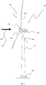
- Fig. 1 shows a wind turbine 100 with a tower 101 raising from a foundation 102 and ended in a nacelle 103 with a wind turbine rotor 104 comprising, in this embodiment, three blades 105', 105", 105'" assembled in a hub 106.
- the nacelle 103 is rotably mounted on the tower 101 configured to face the wind 108 so that the wind 107 will rotate the turbine rotor 104 with a rotational speed depending on the wind speed 108.
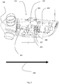
- Fig. 2 shows an embodiment of a drive train 200 placed in the nacelle 104 of the wind turbine 100.
- the drive train 200 connects the hub 106 via a shaft 201 to a gear box 202 that transforms the power to a primary generator shaft 204 that drives a primary generator 205.
- the primary generator shaft 204 transfers power via a mechanical coupling 206 made as a toothed belt type arrangement to a secondary generator shaft 207 that drives a secondary generator 208.
- the primary generator 205 is a Doubly Fed Induction Generator (DFIG) type generator.
- the secondary generator 208 is Permanent Magnet Motor System type generator.
- FIG. 3 shows three different embodiments of primary and secondary generator configurations.
- the embodiments in A, B, and C are exemplified by schematic layouts of configurations of the drive train 200 for a wind 107 interacting with the wind turbine rotor 104 transferring power to the shaft 201 and from there to a primary generator 205 and a secondary generator 208.
- the primary generator 205 and the secondary generator 208 are connected via power lines 300 suitable for conducting power at the required levels to a back-to-back converter 301 in a configuration where the generators 205, 208 connect to the back-to-back converter 301 at a generator side converter end 302 and which back-to-back converter 301 at its grid side converter end 303 connects to a grid 304 at a grid connection 305.
- An electric output of the primary generator 205 is directly coupled to the grid connection 305 point via direct power lines 300.
- an electric power output from the primary generator 205 is coupled to the back-to-back converter 301 via power lines 300.
- the primary generator shaft 204 of the primary generator 205 interacts with the shaft 201 via a gearbox 202 that transforms the power to a primary generator shaft 204.
- the primary generator shaft 204 interacts with a mechanical coupling 206 that in this embodiment is a toothed belt arrangement 206' that transfers power from the primary generator shaft 204 to the secondary generator shaft 207 that drives the secondary generator 208.
- the electric output from the secondary generator 208 is directly coupled to the power lines 300 between the output of the primary generator 205 and the generator side converter end 302.
- Fig. 3B shows another embodiment in which the secondary generator shaft 206 is directly mechanical coupled or engaged to the primary generator shaft 204 via a shaft extension 206".
- the electric output from the secondary generator 208 is directly coupled to the power lines 300 between the output of the primary generator 205 and the generator side converter end 302.
- Fig. 3C shows another embodiment in which the second generator shaft 207 interacts with the shaft 201 via a mechanical coupling 206 that is a secondary gear box 206"'.
- the electric output from the secondary generator 208 is directly coupled to the power lines 300 between the output of the primary generator 205 and the generator side converter end 302.
- the primary generator 205 is a Doubly Fed Induction Generator (DFIG) type generator.
- the secondary generator 208 is Permanent Magnet (PM) type generator such as a PMMS (Permanent Magnet Motor System), a PMHS (Permanent Magnet Hysteresis Synchronous), or a PMDD (Permanent Magnet Direct Drive).
- PMMS Permanent Magnet Motor System
- PMHS Permanent Magnet Hysteresis Synchronous
- PMDD Permanent Magnet Direct Drive
- Fig. 4 shows a representative embodiment of a control and switch configuration applied to the embodiment from Fig. 3A .
- first switch 401 there is a first switch 401 arrangement in the power lines 300 between the primary generator 205 and the grid connection 305 point.
- the first switch 401 is configured to switch on and off electric power output from the primary generator 205 directly to the grid connection 305 point.
- the second switch 402 is configured to switch on and off electric power output from the secondary generator 208 to the generator side converter end 302 of the back-to-back converter 301.
- the third switch 403 is configured to switch on and off electric power output from the secondary generator 208 to the generator side converter end 302 of the back-to-back converter 301.
- the second switch 402 and the third switch 403 are configured as SPDT-switch.
- the switches 401, 402, 403 are implied to be controlled by a controller 405.
- the controller 405 can be configured to control the generator side converter end 302 by generator side controls 406 so as to adapt the back-to-back converter 301 to the power flowing from the generators 205, 208 according to the positions of the switches 401, 402, 403.
- controller 405 can be configured to control the grid side converter end 303 by grid side controls 407.
- the controller 405 also controls the wind turbine 100 elements and in particular the rotation or operation of the wind turbine rotor 104 by means of rotor controls 408.
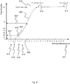
- Fig. 5 shows as an example the efficiency of the drive train 200 of a wind turbine 100 of a standard 1.5MW as a function of the wind speed 108 normalised to the rated power of the wind turbine 100.
- the annual wind distribution 500 is indicated and seen to peak at about 39 % of the rated power, before the annual wind distribution 500 slowly tails off.
- the graph shows the DFIG drive train efficiency 501, which is seen to step-wise raise from 0 % to about 68 % at a rated wind speed 108 of about 35 %, which is just below the peak of annual wind distribution 500, hence capturing the majority of the energy in the wind.
- the graph shows the secondary generator 208 of the permanent magnet types drive train efficiencies: the PMHS drive train efficiency 502, the PMMS drive train efficiency 503, and the PMDD drive train efficiency 504.
- the PM drive train efficiencies 502, 503, 504 show substantially efficiencies at wind speeds 108 below the cut-in wind speed 108 of the DFIG generator 205.
- the graph shows the power curve of the wind turbine power 505 for a drive train 200 combining a primary generator 205 of the DFIG-type and a secondary generator 208 of the PM-type.
- Fig. 6 shows an example of a power curve of the combined output of a primary generator 205 and a secondary generator 206 as disclosed.
- the graph shows the response of the wind turbine 100 for a particular wind speed, W, 600 where the wind turbine 100 generates a power output P, 601.
- the primary generator 205 contributes with a power P p 602
- the secondary generator 208 contributes with a power P s 603.
- the primary generator 205 has a positive power output P p between a minimum wind speed Wp MIN 610 and a maximum wind speed Wp MAX 611.
- the secondary generator 208 has positive power output P s between a minimum wind speed Ws MIN 612 and a maximum wind speed Ws MAX 613.
- the wind turbine 100 is configured so that it from a rated wind speed W rated 615 and above essentially produces the rated power P rated 616.
- the wind turbine 100 is further configured to cut out at a wind speed W cut-out 617 at which wind speed the wind turbine rotor is brought to a halt.
- PMHS Permanent Magnet Hysteresis Synchronous
- PMDD Permanent Magnet Direct Drive
Landscapes
- Engineering & Computer Science (AREA)
- Life Sciences & Earth Sciences (AREA)
- Sustainable Development (AREA)
- Sustainable Energy (AREA)
- Chemical & Material Sciences (AREA)
- Combustion & Propulsion (AREA)
- Mechanical Engineering (AREA)
- General Engineering & Computer Science (AREA)
- Power Engineering (AREA)
- Control Of Eletrric Generators (AREA)
- Wind Motors (AREA)
Claims (14)
- Windturbine (100) vom Typ mit variabler Geschwindigkeit, umfassend:- einen Windturbinenturm (101);- eine Gondel (103), die an der Windturbine (100) vorgesehen ist;- eine Windturbinen-Rotornabe (106), die drehbar an der Gondel (103) befestigt ist, wobei die Windturbinen-Rotornabe (106) mindestens ein Rotorblatt (105) aufweist, das daran befestigt ist;- eine Welle (201), die mit der Windturbinen-Rotornabe (106) und mit, optional durch, ein Getriebe (202) gekoppelt ist,- einen Primärgenerator (205), der einen Primärstator aufweist, der über Stromleitungen (300) elektrisch mit einem Netzanschluss (305) verbunden ist, und einen Primärrotor, der elektrisch verbunden ist mit- einem Gleichstromkurzkupplungswandler (301) an einem generatorseitigen Wandlerende (302) und wobei der Gleichstromkurzkupplungswandler (301) an einem netzseitigen Wandlerende (303) elektrisch mit dem Netzanschluss (305) verbunden ist;- einen Sekundärgenerator (208), der über eine mechanische Verbindung (206) mit der Welle (201, 204) gekoppelt ist, dadurch gekennzeichnet, dass der Sekundärgenerator (208) mit dem Primärrotor des Primärgenerators (205) und dem generatorseitigen Wandlerende (302) des Gleichstromkurzkupplungswandlers (301) elektrisch verbunden ist; und wobei die Windturbine (100) ferner umfasst:- eine Steuereinrichtung (405) mit Steuerungsfähigkeiten und Verbindungseinrichtungen zu:und wobei die Steuereinrichtung (405) und die Schalter (401, 402, 403) konfiguriert sind, um Strom von dem Primärgenerator (205) und dem Sekundärgenerator (208) zum Gleichstromkurzkupplungswandler (301) und einem Netz (304) ein- und auszuschalten.- einem ersten Schalter (401) zwischen dem Primärgenerator (205) und dem Netzanschluss (305);- einem zweiten Schalter (402) zwischen dem generatorseitigen Wandlerende (302) des Gleichstromkurzkupplungswandlers (301) und dem Sekundärgenerator (208);- einem dritten Schalter (403) zwischen dem generatorseitigen Wandlerende (302) des Gleichstromkurzkupplungswandlers (301) und dem Primärgenerator (205);
- Windturbine (100) nach Anspruch 1, dadurch gekennzeichnet, dass der Primärgenerator (205) ein DFIG-Generator (205') ist.
- Windturbine (100) nach Anspruch 1 oder 2, dadurch gekennzeichnet, dass der Sekundärgenerator (208) ein Dauermagnetgenerator ist, wie ein PMHS (208'), PMMS (208"), PMDD (208''') oder ein alternativer oder äquivalenter Dauermagnetgenerator (208).
- Windturbine (100) nach einem der Ansprüche 1 bis 3, dadurch gekennzeichnet, dass der Sekundärgenerator (208) eine maximale Ausgangsleistung (Ps) von zwischen 50 kW und 230 kW aufweist und/oder der Primärgenerator (205) eine maximale Ausgangsleistung (Pp) von mindestens 1 MW, vorzugsweise ungefähr 1,5 MW, aufweist.
- Windturbine (100) nach einem der Ansprüche 1 bis 4, dadurch gekennzeichnet, dass die Steuereinrichtung (405) konfiguriert ist, um mindestens einen der Schalter (401, 402, 403) für einen Stromfluss zwischen aus (null Stromdurchsatz) und ein (maximaler Stromdurchsatz) zu steuern und ständig zu regulieren.
- Windturbine (100) nach einem der Ansprüche 1 bis 5, dadurch gekennzeichnet, dass die Steuereinrichtung (405) ferner konfiguriert ist, um das generatorseitige Wandlerende (302) des Gleichstromkurzkupplungswandlers (301) über generatorseitige Steuerungen (406) zu steuern und/oder das netzseitige Wandlerende (303) des Gleichstromkurzkupplungswandlers (301) über netzseitige Steuerungen (407) zu steuern und/oder die Drehung des Windturbinenrotors (104) mittels Rotorsteuerungen (408) zu steuern.
- Windturbine (100) nach einem der Ansprüche 1 bis 6, dadurch gekennzeichnet, dass der Sekundärgenerator (208) eine Sekundärgeneratorwelle (207) umfasst, die mechanisch mit einer Primärgeneratorwelle (204) gekoppelt ist, wobei die mechanische Verbindung (206) vorzugsweise eine Verbindung vom Typ eines Zahnriemens (206') ist.
- Windturbine (100) nach einem der Ansprüche 1 bis 8, dadurch gekennzeichnet, dass der Sekundärgenerator (208) eine Sekundärgeneratorwelle (207) umfasst, die mechanisch direkt mit einer Primärgeneratorwelle (204) gekoppelt ist, wobei die mechanische Verbindung (206) vorzugsweise eine Eins-zu-Eins-Direktverbindung ist, wie eine Wellenverlängerung (206").
- Windturbine (100) nach einem der Ansprüche 1 bis 6, dadurch gekennzeichnet, dass der Sekundärgenerator (208) eine Sekundärgeneratorwelle (207) umfasst, die mechanisch durch eine Verbindung (206) mit der Welle (201) gekoppelt ist, wobei die mechanische Verbindung (206) vorzugsweise eine Verbindung vom Typ eines Sekundärgetriebes (206"") ist.
- Verfahren zum Herstellen einer Windturbine (100) nach einem der Ansprüche 1 - 9, umfassend die folgenden Schritte:- Bereitstellen einer Windturbine (100) vom Typ mit variabler Geschwindigkeit, umfassend:- einen Windturbinenturm (101);- eine Gondel (103), die an der Windturbine (100) vorgesehen ist;- eine Windturbinen-Rotornabe (106), die drehbar an der Gondel (103) befestigt ist, wobei die Windturbinen-Rotornabe (106) mindestens ein Rotorblatt (105) aufweist, das daran befestigt ist;- eine Welle (201), die mit der Windturbinen-Rotornabe (106) und mit, optional durch, ein Getriebe (202) gekoppelt ist,- einen Primärgenerator (205), der einen Primärstator aufweist, der über Stromleitungen (300) elektrisch mit einem Netzanschluss (305) verbunden ist, und einen Primärrotor, der elektrisch verbunden ist mit- einem Gleichstromkurzkupplungswandler (301) an einem generatorseitigen Wandlerende (302) und wobei der Gleichstromkurzkupplungswandler (301) an einem netzseitigen Wandlerende (303) elektrisch mit dem Netzanschluss (305) verbunden ist;- Bereitstellen eines Sekundärgenerators (208); gekennzeichnet durch- Nachrüsten des Sekundärgenerators (208) an der Welle (201) oder einer Primärgeneratorwelle (204) durch eine mechanische Verbindung (206) und elektrisches Verbinden des Sekundärgenerators (208) mit dem Primärrotor des Primärgenerators (116) und dem Gleichstromkurzkupplungswandler (301); und- Nachrüsten- eines ersten Schalters (401) zwischen dem Primärgenerator (205) und dem Netzanschluss (305);- eines zweiten Schalters (402) zwischen dem generatorseitigen Ende (302) des Gleichstromkurzkupplungswandlers (301) und dem Sekundärgenerator (208);- eines dritten Schalters (403) zwischen dem generatorseitigen Wandlerende (302) des Gleichstromkurzkupplungswandlers (301) und dem Primärgenerator (205);und wobei die Steuereinrichtung (405) und die Schalter (401, 402, 403) konfiguriert sind, um Strom von dem Primärgenerator (205) und dem Sekundärgenerator (208) zum Gleichstromkurzkupplungswandler (301) und einem Netz (304) ein- und auszuschalten;- Nachrüsten der Steuereinrichtung (405), um den Gleichstromkurzkupplungswandler (301) über generator-/netzseitige Steuerungen (406, 407) zu steuern.
- Verfahren zum Herstellen einer Windturbine (100) nach Anspruch 10, wobei die Steuereinrichtung (405) ferner nachgerüstet wird, um die Drehung des Windturbinenrotors (104) mittels Rotorsteuerungen (408) zu steuern.
- Verfahren zum Betreiben einer Windturbine (100) nach einem der Ansprüche 1 bis 9 und wobei- der Primärgenerator (205) mit einem Windturbinenrotor (104) gekoppelt ist und konfiguriert ist, um eine Ausgangsleistung Pp (602) zu liefern, wenn der Windturbinenrotor (104) eine Windgeschwindigkeit zwischen einer minimalen Primärwindgeschwindigkeit (Wp MIN) und einer maximalen Primärwindgeschwindigkeit (Wp MAX) erfährt; und- der Sekundärgenerator (208) mit einem Windturbinenrotor (104) gekoppelt ist und konfiguriert ist, um eine Ausgangsleistung (Ps) zu liefern, wenn der Windturbinenrotor (104) eine Windgeschwindigkeit zwischen einer minimalen Sekundärwindgeschwindigkeit (Ws MIN) und einer maximalen Sekundärwindgeschwindigkeit (Ws MAX) erfährt;- und wobei der Primärgenerator (205) und der Sekundärgenerator (208) konfiguriert sind, um eine Gesamtausgangsleistung (P) zu erzeugen; wobei das Verfahren zum Betreiben die folgenden Schritte umfasst:- Betreiben der Windturbine in einem Primärbetriebsmodus, bei dem die Ausgangsleistung (P) vom Primärgenerator (205) kommt, wenn die Windgeschwindigkeit über einer Entkopplungswindgeschwindigkeit (WEntkopplung) liegt;- Betreiben der Windturbine in einem Sekundärbetriebsmodus, bei dem die Ausgangsleistung (P) von dem Sekundärgenerator (208) kommt, wenn die Windgeschwindigkeit unter der Entkopplungsgeschwindigkeit (WEntkopplung) liegt;- und wobei die Entkopplungsgeschwindigkeit (WEntkopplung) zwischen der minimalen Primärwindgeschwindigkeit (Ws MIN) und der maximalen Sekundärwindgeschwindigkeit (Ws MAX) liegt.
- Verfahren zum Betreiben einer Windturbine (100) nach Anspruch 12, wobei die Windturbine (100) von dem einen zum anderen Betriebsmodus umschaltet, umfassend die folgenden Schritte:- Erfassen eines Durchlaufens der Entkopplungswindgeschwindigkeit (WEntkopplung) ;- Stoppen der Drehung des Windturbinenrotors (104) der Windturbine (100),- Neustarten der Drehung des Windturbinenrotors (104) der Windturbine (100) durch- Eintreten in den Primärbetriebsmodus, wenn die Windgeschwindigkeit (W) bei oder über der Entkopplungswindgeschwindigkeit (WEntkopplung) liegt oder- Eintreten in den Sekundärbetriebsmodus, wenn die Windgeschwindigkeit (W) unter der Entkopplungswindgeschwindigkeit (WEntkopplung) liegt.
- Verfahren zum Betreiben einer Windturbine (100) nach Anspruch 12, wobei die Windturbine (100) von dem einen zum anderen Betriebsmodus umschaltet, umfassend die folgenden Schritte:- Verringern der Ausgangsleistung (P) auf Null, während der Windturbinenrotor (104) bei einer bestimmten Drehzahl gehalten wird;- Einschalten der ersten Schalter (401) und der dritten Schalter (403), um den Primärgenerator (205) mit einem Netz (305) zu verbinden und die Leistung auf das erforderliche Leistungsniveau hochzufahren;- Betreiben im Primärbetriebsmodus;
oder- Einschalten der zweiten Schalter (402), um den Sekundärgenerator (208) mit einem Netz (305) zu verbinden und die Leistung auf das erforderliche Leistungsniveau hochzufahren;- Betreiben im Sekundärbetriebsmodus.
Applications Claiming Priority (1)
| Application Number | Priority Date | Filing Date | Title |
|---|---|---|---|
| DKPA201270189A DK177553B1 (en) | 2012-04-16 | 2012-04-16 | Wind Turbine with a Primary and a Secondary Generator and Method of Operating such Wind Turbine |
Publications (3)
| Publication Number | Publication Date |
|---|---|
| EP2653720A2 EP2653720A2 (de) | 2013-10-23 |
| EP2653720A3 EP2653720A3 (de) | 2016-09-28 |
| EP2653720B1 true EP2653720B1 (de) | 2017-07-12 |
Family
ID=48083057
Family Applications (1)
| Application Number | Title | Priority Date | Filing Date |
|---|---|---|---|
| EP13163749.8A Not-in-force EP2653720B1 (de) | 2012-04-16 | 2013-04-15 | Windturbine mit einem Primär- und Sekundärgenerator und Verfahren zum Betrieb solch einer Windturbine |
Country Status (6)
| Country | Link |
|---|---|
| US (1) | US8796873B2 (de) |
| EP (1) | EP2653720B1 (de) |
| CN (1) | CN103375350B (de) |
| CA (1) | CA2812591C (de) |
| DK (1) | DK177553B1 (de) |
| ES (1) | ES2643238T3 (de) |
Families Citing this family (14)
| Publication number | Priority date | Publication date | Assignee | Title |
|---|---|---|---|---|
| AT514239B1 (de) * | 2013-04-18 | 2015-02-15 | Set Sustainable Energy Technologies Gmbh | Antrieb und Verfahren zum Betreiben eines solchen Antriebs |
| WO2014173808A1 (en) * | 2013-04-23 | 2014-10-30 | youWINenergy GmbH | Wind turbine architecture |
| US20150115607A1 (en) * | 2013-10-27 | 2015-04-30 | Lev Stepanov | Method of increasing of sensitivity and productivity of the wind generator with vertical axis at weak winds and device for his realization |
| CN106469965B (zh) * | 2015-08-05 | 2019-04-12 | 江苏金源高端装备股份有限公司 | 一种风力发电机供电系统 |
| US9816487B2 (en) * | 2015-09-23 | 2017-11-14 | Bala Govind | System and method for integrating a horizontal axis wind turbine and a vertical axis wind turbine |
| DE102016103254A1 (de) * | 2016-02-24 | 2017-08-24 | Wobben Properties Gmbh | Verfahren zum Bestimmen einer äquivalenten Windgeschwindigkeit |
| CN105932714B (zh) * | 2016-06-16 | 2018-11-13 | 三一重型能源装备有限公司 | 双电机风力发电机并网装置、风力发电机及并网控制方法 |
| CN106089579B (zh) * | 2016-06-16 | 2019-08-16 | 三一重型能源装备有限公司 | 风力发电机组的控制方法和系统 |
| WO2018139004A1 (ja) * | 2017-01-24 | 2018-08-02 | 住友電気工業株式会社 | エネルギー貯蔵システムおよび変動電力安定利用システム |
| CN110873025B (zh) * | 2018-09-04 | 2022-01-14 | 郑州宇通重工有限公司 | 环卫车排风能量回收控制方法、控制装置和环卫车 |
| CN110807977B (zh) * | 2019-11-29 | 2021-07-30 | 南京康尼电气技术有限公司 | 一种风力发电实验平台及实验方法 |
| EP3905472A1 (de) * | 2020-04-27 | 2021-11-03 | Siemens Gamesa Renewable Energy Innovation & Technology, S.L. | Stromerzeugungssystem einer windturbine |
| CN111664056B (zh) * | 2020-06-22 | 2025-01-03 | 瑞安市源霸机械制造有限公司 | 信号塔风力发电装置 |
| CN114704429B (zh) * | 2022-03-23 | 2025-11-14 | 青岛星光风电设备科技有限公司 | 一种自扭力磁阻变桨距风力发电机 |
Family Cites Families (21)
| Publication number | Priority date | Publication date | Assignee | Title |
|---|---|---|---|---|
| GB295252A (en) * | 1927-05-07 | 1928-08-07 | Dudley Eugene Batty | Improvements in or relating to electric generating systems |
| US4446376A (en) * | 1981-05-18 | 1984-05-01 | Baker Carl R | Auxiliary power supply switching set |
| US4572961A (en) * | 1984-04-18 | 1986-02-25 | The United States Of America As Represented By The Secretary Of The Air Force | Constant speed drive with compensation using differential gears |
| US4613760A (en) * | 1984-09-12 | 1986-09-23 | The English Electric Company Limited | Power generating equipment |
| US4585950A (en) * | 1984-12-06 | 1986-04-29 | Lund Arnold M | Wind turbine with multiple generators |
| US4908565A (en) | 1987-02-18 | 1990-03-13 | Sundstrand Corporation | Power generating system |
| US5140856A (en) * | 1990-12-03 | 1992-08-25 | Dynamic Rotor Balancing, Inc. | In situ balancing of wind turbines |
| US6304002B1 (en) * | 2000-04-19 | 2001-10-16 | Dehlsen Associates, L.L.C. | Distributed powertrain for high torque, low electric power generator |
| JP2003102199A (ja) | 2001-07-19 | 2003-04-04 | Yamaha Motor Co Ltd | インバータ式発電機 |
| JP2003056446A (ja) * | 2001-08-10 | 2003-02-26 | Kanki Kenzo | 風力発電装置 |
| WO2005046044A1 (en) * | 2003-11-06 | 2005-05-19 | Varispeed Electric Motors Pty Ltd | A variable speed power generator having two induction generators on a common shaft |
| US7285871B2 (en) * | 2004-08-25 | 2007-10-23 | Honeywell International, Inc. | Engine power extraction control system |
| US7552582B2 (en) * | 2005-06-07 | 2009-06-30 | Honeywell International Inc. | More electric aircraft power transfer systems and methods |
| KR100668118B1 (ko) * | 2005-12-30 | 2007-01-16 | 한국전기연구원 | 권선형 유도 발전기 제어용 전력변환장치 및 전력변환방법 |
| US7481062B2 (en) * | 2005-12-30 | 2009-01-27 | Honeywell International Inc. | More electric aircraft starter-generator multi-speed transmission system |
| US7425771B2 (en) * | 2006-03-17 | 2008-09-16 | Ingeteam S.A. | Variable speed wind turbine having an exciter machine and a power converter not connected to the grid |
| TWI336160B (en) * | 2006-12-01 | 2011-01-11 | Ind Tech Res Inst | Hybrid power-generating device |
| CN101205874B (zh) * | 2006-12-21 | 2011-06-15 | 财团法人工业技术研究院 | 具有自供电系统的发电装置 |
| CN101207313B (zh) * | 2006-12-22 | 2011-03-30 | 财团法人工业技术研究院 | 具有复合式发电机的发电装置及其发电方法 |
| ES2410604B1 (es) * | 2011-12-29 | 2014-06-24 | Gamesa Innovation & Technology, S.L. | Método y dispositivo de conversion para ensayar aerogeneradores en campo |
| CN103378742B (zh) * | 2012-04-18 | 2016-02-03 | 台达电子企业管理(上海)有限公司 | 变流器系统及其控制方法 |
-
2012
- 2012-04-16 DK DKPA201270189A patent/DK177553B1/en not_active IP Right Cessation
-
2013
- 2013-03-15 CN CN201310082968.9A patent/CN103375350B/zh active Active
- 2013-04-15 CA CA2812591A patent/CA2812591C/en not_active Expired - Fee Related
- 2013-04-15 EP EP13163749.8A patent/EP2653720B1/de not_active Not-in-force
- 2013-04-15 ES ES13163749.8T patent/ES2643238T3/es active Active
- 2013-04-16 US US13/863,539 patent/US8796873B2/en not_active Expired - Fee Related
Non-Patent Citations (1)
| Title |
|---|
| None * |
Also Published As
| Publication number | Publication date |
|---|---|
| CA2812591A1 (en) | 2013-10-16 |
| CA2812591C (en) | 2018-02-27 |
| EP2653720A2 (de) | 2013-10-23 |
| EP2653720A3 (de) | 2016-09-28 |
| US8796873B2 (en) | 2014-08-05 |
| DK177553B1 (en) | 2013-10-07 |
| CN103375350A (zh) | 2013-10-30 |
| ES2643238T3 (es) | 2017-11-21 |
| CN103375350B (zh) | 2016-03-16 |
| US20130270826A1 (en) | 2013-10-17 |
Similar Documents
| Publication | Publication Date | Title |
|---|---|---|
| EP2653720B1 (de) | Windturbine mit einem Primär- und Sekundärgenerator und Verfahren zum Betrieb solch einer Windturbine | |
| DK2161443T3 (en) | Wind turbine having a main power converter and an auxiliary power converter and a method of controlling thereof | |
| CN107208608B (zh) | 用于运行风电场的方法 | |
| EP3004637A1 (de) | Verfahren zum betreiben eines windturbinensystems mit dynamischer bremse | |
| EP3276819B1 (de) | Elektrischer stromkreis und verfahren zum betrieb davon | |
| US11448188B2 (en) | Power converter control and operation | |
| US10855079B1 (en) | System and method for reducing oscillations in a renewable energy power system | |
| CN102522777A (zh) | 一种风力发电机组 | |
| EP3745551B1 (de) | System und verfahren zur steuerung der harmonischen oberwellen in einem energiesystem für erneuerbare energien | |
| CN113541180A (zh) | 用于控制风力涡轮机转换器的系统和方法 | |
| US12152567B2 (en) | Method for operating a wind farm and a wind farm | |
| US10975847B1 (en) | System and method for farm-level control of transient power boost during frequency events | |
| US11879433B2 (en) | Method for operating a wind turbine, and a power plant | |
| US20230178994A1 (en) | Method for operating a wind farm and a wind farm | |
| US12203447B2 (en) | Method for operating a wind turbine and a wind turbine | |
| US12129828B2 (en) | Method for operating a wind turbine, and a power plant | |
| KR20100114387A (ko) | 선택적 발전방식을 사용하는 풍력 발전기 및 그의 발전 제어방법 | |
| CN202159983U (zh) | 一种用于双馈风力发电机的零电压穿越系统 | |
| EP4609500A1 (de) | System und verfahren zur erweiterung der betriebsgeschwindigkeitsschwelle einer netzbildenden wechselrichterbasierten ressource | |
| CN112443455A (zh) | 在低风速期间操作风力涡轮功率系统的系统和方法 |
Legal Events
| Date | Code | Title | Description |
|---|---|---|---|
| PUAI | Public reference made under article 153(3) epc to a published international application that has entered the european phase |
Free format text: ORIGINAL CODE: 0009012 |
|
| AK | Designated contracting states |
Kind code of ref document: A2 Designated state(s): AL AT BE BG CH CY CZ DE DK EE ES FI FR GB GR HR HU IE IS IT LI LT LU LV MC MK MT NL NO PL PT RO RS SE SI SK SM TR |
|
| AX | Request for extension of the european patent |
Extension state: BA ME |
|
| PUAL | Search report despatched |
Free format text: ORIGINAL CODE: 0009013 |
|
| AK | Designated contracting states |
Kind code of ref document: A3 Designated state(s): AL AT BE BG CH CY CZ DE DK EE ES FI FR GB GR HR HU IE IS IT LI LT LU LV MC MK MT NL NO PL PT RO RS SE SI SK SM TR |
|
| AX | Request for extension of the european patent |
Extension state: BA ME |
|
| RIC1 | Information provided on ipc code assigned before grant |
Ipc: H02P 9/00 20060101ALI20160825BHEP Ipc: F03D 9/00 20160101AFI20160825BHEP |
|
| 17P | Request for examination filed |
Effective date: 20161115 |
|
| RBV | Designated contracting states (corrected) |
Designated state(s): AL AT BE BG CH CY CZ DE DK EE ES FI FR GB GR HR HU IE IS IT LI LT LU LV MC MK MT NL NO PL PT RO RS SE SI SK SM TR |
|
| GRAP | Despatch of communication of intention to grant a patent |
Free format text: ORIGINAL CODE: EPIDOSNIGR1 |
|
| RIC1 | Information provided on ipc code assigned before grant |
Ipc: H02P 9/00 20060101ALI20170228BHEP Ipc: F03D 9/00 20160101AFI20170228BHEP Ipc: F03D 9/25 20160101ALI20170228BHEP |
|
| INTG | Intention to grant announced |
Effective date: 20170405 |
|
| GRAS | Grant fee paid |
Free format text: ORIGINAL CODE: EPIDOSNIGR3 |
|
| GRAA | (expected) grant |
Free format text: ORIGINAL CODE: 0009210 |
|
| AK | Designated contracting states |
Kind code of ref document: B1 Designated state(s): AL AT BE BG CH CY CZ DE DK EE ES FI FR GB GR HR HU IE IS IT LI LT LU LV MC MK MT NL NO PL PT RO RS SE SI SK SM TR |
|
| REG | Reference to a national code |
Ref country code: GB Ref legal event code: FG4D |
|
| REG | Reference to a national code |
Ref country code: CH Ref legal event code: EP |
|
| REG | Reference to a national code |
Ref country code: AT Ref legal event code: REF Ref document number: 908609 Country of ref document: AT Kind code of ref document: T Effective date: 20170715 |
|
| REG | Reference to a national code |
Ref country code: IE Ref legal event code: FG4D |
|
| REG | Reference to a national code |
Ref country code: DE Ref legal event code: R096 Ref document number: 602013023291 Country of ref document: DE |
|
| REG | Reference to a national code |
Ref country code: NL Ref legal event code: MP Effective date: 20170712 |
|
| REG | Reference to a national code |
Ref country code: ES Ref legal event code: FG2A Ref document number: 2643238 Country of ref document: ES Kind code of ref document: T3 Effective date: 20171121 |
|
| REG | Reference to a national code |
Ref country code: LT Ref legal event code: MG4D |
|
| REG | Reference to a national code |
Ref country code: AT Ref legal event code: MK05 Ref document number: 908609 Country of ref document: AT Kind code of ref document: T Effective date: 20170712 |
|
| PG25 | Lapsed in a contracting state [announced via postgrant information from national office to epo] |
Ref country code: NO Free format text: LAPSE BECAUSE OF FAILURE TO SUBMIT A TRANSLATION OF THE DESCRIPTION OR TO PAY THE FEE WITHIN THE PRESCRIBED TIME-LIMIT Effective date: 20171012 Ref country code: NL Free format text: LAPSE BECAUSE OF FAILURE TO SUBMIT A TRANSLATION OF THE DESCRIPTION OR TO PAY THE FEE WITHIN THE PRESCRIBED TIME-LIMIT Effective date: 20170712 Ref country code: LT Free format text: LAPSE BECAUSE OF FAILURE TO SUBMIT A TRANSLATION OF THE DESCRIPTION OR TO PAY THE FEE WITHIN THE PRESCRIBED TIME-LIMIT Effective date: 20170712 Ref country code: AT Free format text: LAPSE BECAUSE OF FAILURE TO SUBMIT A TRANSLATION OF THE DESCRIPTION OR TO PAY THE FEE WITHIN THE PRESCRIBED TIME-LIMIT Effective date: 20170712 Ref country code: SE Free format text: LAPSE BECAUSE OF FAILURE TO SUBMIT A TRANSLATION OF THE DESCRIPTION OR TO PAY THE FEE WITHIN THE PRESCRIBED TIME-LIMIT Effective date: 20170712 Ref country code: FI Free format text: LAPSE BECAUSE OF FAILURE TO SUBMIT A TRANSLATION OF THE DESCRIPTION OR TO PAY THE FEE WITHIN THE PRESCRIBED TIME-LIMIT Effective date: 20170712 Ref country code: HR Free format text: LAPSE BECAUSE OF FAILURE TO SUBMIT A TRANSLATION OF THE DESCRIPTION OR TO PAY THE FEE WITHIN THE PRESCRIBED TIME-LIMIT Effective date: 20170712 |
|
| PG25 | Lapsed in a contracting state [announced via postgrant information from national office to epo] |
Ref country code: IS Free format text: LAPSE BECAUSE OF FAILURE TO SUBMIT A TRANSLATION OF THE DESCRIPTION OR TO PAY THE FEE WITHIN THE PRESCRIBED TIME-LIMIT Effective date: 20171112 Ref country code: GR Free format text: LAPSE BECAUSE OF FAILURE TO SUBMIT A TRANSLATION OF THE DESCRIPTION OR TO PAY THE FEE WITHIN THE PRESCRIBED TIME-LIMIT Effective date: 20171013 Ref country code: BG Free format text: LAPSE BECAUSE OF FAILURE TO SUBMIT A TRANSLATION OF THE DESCRIPTION OR TO PAY THE FEE WITHIN THE PRESCRIBED TIME-LIMIT Effective date: 20171012 Ref country code: PL Free format text: LAPSE BECAUSE OF FAILURE TO SUBMIT A TRANSLATION OF THE DESCRIPTION OR TO PAY THE FEE WITHIN THE PRESCRIBED TIME-LIMIT Effective date: 20170712 Ref country code: LV Free format text: LAPSE BECAUSE OF FAILURE TO SUBMIT A TRANSLATION OF THE DESCRIPTION OR TO PAY THE FEE WITHIN THE PRESCRIBED TIME-LIMIT Effective date: 20170712 Ref country code: RS Free format text: LAPSE BECAUSE OF FAILURE TO SUBMIT A TRANSLATION OF THE DESCRIPTION OR TO PAY THE FEE WITHIN THE PRESCRIBED TIME-LIMIT Effective date: 20170712 |
|
| REG | Reference to a national code |
Ref country code: DE Ref legal event code: R097 Ref document number: 602013023291 Country of ref document: DE |
|
| REG | Reference to a national code |
Ref country code: FR Ref legal event code: PLFP Year of fee payment: 6 |
|
| PG25 | Lapsed in a contracting state [announced via postgrant information from national office to epo] |
Ref country code: RO Free format text: LAPSE BECAUSE OF FAILURE TO SUBMIT A TRANSLATION OF THE DESCRIPTION OR TO PAY THE FEE WITHIN THE PRESCRIBED TIME-LIMIT Effective date: 20170712 Ref country code: DK Free format text: LAPSE BECAUSE OF FAILURE TO SUBMIT A TRANSLATION OF THE DESCRIPTION OR TO PAY THE FEE WITHIN THE PRESCRIBED TIME-LIMIT Effective date: 20170712 Ref country code: CZ Free format text: LAPSE BECAUSE OF FAILURE TO SUBMIT A TRANSLATION OF THE DESCRIPTION OR TO PAY THE FEE WITHIN THE PRESCRIBED TIME-LIMIT Effective date: 20170712 |
|
| PGFP | Annual fee paid to national office [announced via postgrant information from national office to epo] |
Ref country code: GB Payment date: 20180321 Year of fee payment: 6 |
|
| PLBE | No opposition filed within time limit |
Free format text: ORIGINAL CODE: 0009261 |
|
| STAA | Information on the status of an ep patent application or granted ep patent |
Free format text: STATUS: NO OPPOSITION FILED WITHIN TIME LIMIT |
|
| PG25 | Lapsed in a contracting state [announced via postgrant information from national office to epo] |
Ref country code: SK Free format text: LAPSE BECAUSE OF FAILURE TO SUBMIT A TRANSLATION OF THE DESCRIPTION OR TO PAY THE FEE WITHIN THE PRESCRIBED TIME-LIMIT Effective date: 20170712 Ref country code: IT Free format text: LAPSE BECAUSE OF FAILURE TO SUBMIT A TRANSLATION OF THE DESCRIPTION OR TO PAY THE FEE WITHIN THE PRESCRIBED TIME-LIMIT Effective date: 20170712 Ref country code: EE Free format text: LAPSE BECAUSE OF FAILURE TO SUBMIT A TRANSLATION OF THE DESCRIPTION OR TO PAY THE FEE WITHIN THE PRESCRIBED TIME-LIMIT Effective date: 20170712 Ref country code: SM Free format text: LAPSE BECAUSE OF FAILURE TO SUBMIT A TRANSLATION OF THE DESCRIPTION OR TO PAY THE FEE WITHIN THE PRESCRIBED TIME-LIMIT Effective date: 20170712 |
|
| 26N | No opposition filed |
Effective date: 20180413 |
|
| PGFP | Annual fee paid to national office [announced via postgrant information from national office to epo] |
Ref country code: ES Payment date: 20180502 Year of fee payment: 6 Ref country code: IE Payment date: 20180411 Year of fee payment: 6 Ref country code: DE Payment date: 20180418 Year of fee payment: 6 |
|
| PG25 | Lapsed in a contracting state [announced via postgrant information from national office to epo] |
Ref country code: SI Free format text: LAPSE BECAUSE OF FAILURE TO SUBMIT A TRANSLATION OF THE DESCRIPTION OR TO PAY THE FEE WITHIN THE PRESCRIBED TIME-LIMIT Effective date: 20170712 |
|
| PGFP | Annual fee paid to national office [announced via postgrant information from national office to epo] |
Ref country code: FR Payment date: 20180416 Year of fee payment: 6 |
|
| PG25 | Lapsed in a contracting state [announced via postgrant information from national office to epo] |
Ref country code: MC Free format text: LAPSE BECAUSE OF FAILURE TO SUBMIT A TRANSLATION OF THE DESCRIPTION OR TO PAY THE FEE WITHIN THE PRESCRIBED TIME-LIMIT Effective date: 20170712 |
|
| REG | Reference to a national code |
Ref country code: CH Ref legal event code: PL |
|
| REG | Reference to a national code |
Ref country code: BE Ref legal event code: MM Effective date: 20180430 |
|
| PG25 | Lapsed in a contracting state [announced via postgrant information from national office to epo] |
Ref country code: LU Free format text: LAPSE BECAUSE OF NON-PAYMENT OF DUE FEES Effective date: 20180415 |
|
| PG25 | Lapsed in a contracting state [announced via postgrant information from national office to epo] |
Ref country code: BE Free format text: LAPSE BECAUSE OF NON-PAYMENT OF DUE FEES Effective date: 20180430 Ref country code: CH Free format text: LAPSE BECAUSE OF NON-PAYMENT OF DUE FEES Effective date: 20180430 Ref country code: LI Free format text: LAPSE BECAUSE OF NON-PAYMENT OF DUE FEES Effective date: 20180430 |
|
| REG | Reference to a national code |
Ref country code: DE Ref legal event code: R119 Ref document number: 602013023291 Country of ref document: DE |
|
| GBPC | Gb: european patent ceased through non-payment of renewal fee |
Effective date: 20190415 |
|
| PG25 | Lapsed in a contracting state [announced via postgrant information from national office to epo] |
Ref country code: GB Free format text: LAPSE BECAUSE OF NON-PAYMENT OF DUE FEES Effective date: 20190415 Ref country code: DE Free format text: LAPSE BECAUSE OF NON-PAYMENT OF DUE FEES Effective date: 20191101 Ref country code: MT Free format text: LAPSE BECAUSE OF NON-PAYMENT OF DUE FEES Effective date: 20180415 |
|
| PG25 | Lapsed in a contracting state [announced via postgrant information from national office to epo] |
Ref country code: TR Free format text: LAPSE BECAUSE OF FAILURE TO SUBMIT A TRANSLATION OF THE DESCRIPTION OR TO PAY THE FEE WITHIN THE PRESCRIBED TIME-LIMIT Effective date: 20170712 |
|
| PG25 | Lapsed in a contracting state [announced via postgrant information from national office to epo] |
Ref country code: IE Free format text: LAPSE BECAUSE OF NON-PAYMENT OF DUE FEES Effective date: 20190415 |
|
| PG25 | Lapsed in a contracting state [announced via postgrant information from national office to epo] |
Ref country code: HU Free format text: LAPSE BECAUSE OF FAILURE TO SUBMIT A TRANSLATION OF THE DESCRIPTION OR TO PAY THE FEE WITHIN THE PRESCRIBED TIME-LIMIT; INVALID AB INITIO Effective date: 20130415 Ref country code: PT Free format text: LAPSE BECAUSE OF FAILURE TO SUBMIT A TRANSLATION OF THE DESCRIPTION OR TO PAY THE FEE WITHIN THE PRESCRIBED TIME-LIMIT Effective date: 20170712 |
|
| PG25 | Lapsed in a contracting state [announced via postgrant information from national office to epo] |
Ref country code: FR Free format text: LAPSE BECAUSE OF NON-PAYMENT OF DUE FEES Effective date: 20190430 Ref country code: MK Free format text: LAPSE BECAUSE OF NON-PAYMENT OF DUE FEES Effective date: 20170712 Ref country code: CY Free format text: LAPSE BECAUSE OF FAILURE TO SUBMIT A TRANSLATION OF THE DESCRIPTION OR TO PAY THE FEE WITHIN THE PRESCRIBED TIME-LIMIT Effective date: 20170712 |
|
| PG25 | Lapsed in a contracting state [announced via postgrant information from national office to epo] |
Ref country code: AL Free format text: LAPSE BECAUSE OF FAILURE TO SUBMIT A TRANSLATION OF THE DESCRIPTION OR TO PAY THE FEE WITHIN THE PRESCRIBED TIME-LIMIT Effective date: 20170712 |
|
| REG | Reference to a national code |
Ref country code: ES Ref legal event code: FD2A Effective date: 20200831 |
|
| PG25 | Lapsed in a contracting state [announced via postgrant information from national office to epo] |
Ref country code: ES Free format text: LAPSE BECAUSE OF NON-PAYMENT OF DUE FEES Effective date: 20190416 |