EP2653652A2 - Axially-split radial turbine - Google Patents
Axially-split radial turbine Download PDFInfo
- Publication number
- EP2653652A2 EP2653652A2 EP20130162820 EP13162820A EP2653652A2 EP 2653652 A2 EP2653652 A2 EP 2653652A2 EP 20130162820 EP20130162820 EP 20130162820 EP 13162820 A EP13162820 A EP 13162820A EP 2653652 A2 EP2653652 A2 EP 2653652A2
- Authority
- EP
- European Patent Office
- Prior art keywords
- aft
- axially
- turbine
- radial turbine
- section
- Prior art date
- Legal status (The legal status is an assumption and is not a legal conclusion. Google has not performed a legal analysis and makes no representation as to the accuracy of the status listed.)
- Granted
Links
- 238000001816 cooling Methods 0.000 claims description 34
- 230000008878 coupling Effects 0.000 claims description 2
- 238000010168 coupling process Methods 0.000 claims description 2
- 238000005859 coupling reaction Methods 0.000 claims description 2
- 230000013011 mating Effects 0.000 claims description 2
- 230000035882 stress Effects 0.000 description 12
- 238000005266 casting Methods 0.000 description 11
- 239000000463 material Substances 0.000 description 11
- 229910000601 superalloy Inorganic materials 0.000 description 9
- PXHVJJICTQNCMI-UHFFFAOYSA-N Nickel Chemical compound [Ni] PXHVJJICTQNCMI-UHFFFAOYSA-N 0.000 description 8
- 238000002485 combustion reaction Methods 0.000 description 8
- 229910045601 alloy Inorganic materials 0.000 description 7
- 239000000956 alloy Substances 0.000 description 7
- 238000004519 manufacturing process Methods 0.000 description 7
- 238000000034 method Methods 0.000 description 6
- 230000008901 benefit Effects 0.000 description 5
- 230000008569 process Effects 0.000 description 5
- 230000015572 biosynthetic process Effects 0.000 description 4
- 239000013078 crystal Substances 0.000 description 4
- 229910052759 nickel Inorganic materials 0.000 description 4
- 230000003647 oxidation Effects 0.000 description 4
- 238000007254 oxidation reaction Methods 0.000 description 4
- 238000005219 brazing Methods 0.000 description 3
- 238000010276 construction Methods 0.000 description 3
- 238000009792 diffusion process Methods 0.000 description 3
- 238000003754 machining Methods 0.000 description 3
- 229910052751 metal Inorganic materials 0.000 description 3
- 239000002184 metal Substances 0.000 description 3
- 239000000446 fuel Substances 0.000 description 2
- 239000000411 inducer Substances 0.000 description 2
- 230000009467 reduction Effects 0.000 description 2
- 230000001052 transient effect Effects 0.000 description 2
- 238000011144 upstream manufacturing Methods 0.000 description 2
- 229910001011 CMSX-4 Inorganic materials 0.000 description 1
- RTAQQCXQSZGOHL-UHFFFAOYSA-N Titanium Chemical compound [Ti] RTAQQCXQSZGOHL-UHFFFAOYSA-N 0.000 description 1
- 238000002144 chemical decomposition reaction Methods 0.000 description 1
- 239000012141 concentrate Substances 0.000 description 1
- 238000007596 consolidation process Methods 0.000 description 1
- 230000003247 decreasing effect Effects 0.000 description 1
- 230000007547 defect Effects 0.000 description 1
- 230000002950 deficient Effects 0.000 description 1
- 238000005242 forging Methods 0.000 description 1
- 230000036316 preload Effects 0.000 description 1
- 238000007363 ring formation reaction Methods 0.000 description 1
- 238000005476 soldering Methods 0.000 description 1
- 230000008646 thermal stress Effects 0.000 description 1
- 239000010936 titanium Substances 0.000 description 1
- 229910052719 titanium Inorganic materials 0.000 description 1
- 229940035289 tobi Drugs 0.000 description 1
- NLVFBUXFDBBNBW-PBSUHMDJSA-N tobramycin Chemical compound N[C@@H]1C[C@H](O)[C@@H](CN)O[C@@H]1O[C@H]1[C@H](O)[C@@H](O[C@@H]2[C@@H]([C@@H](N)[C@H](O)[C@@H](CO)O2)O)[C@H](N)C[C@@H]1N NLVFBUXFDBBNBW-PBSUHMDJSA-N 0.000 description 1
- 230000007704 transition Effects 0.000 description 1
Images


Classifications
-
- F—MECHANICAL ENGINEERING; LIGHTING; HEATING; WEAPONS; BLASTING
- F01—MACHINES OR ENGINES IN GENERAL; ENGINE PLANTS IN GENERAL; STEAM ENGINES
- F01D—NON-POSITIVE DISPLACEMENT MACHINES OR ENGINES, e.g. STEAM TURBINES
- F01D5/00—Blades; Blade-carrying members; Heating, heat-insulating, cooling or antivibration means on the blades or the members
- F01D5/02—Blade-carrying members, e.g. rotors
- F01D5/026—Shaft to shaft connections
-
- F—MECHANICAL ENGINEERING; LIGHTING; HEATING; WEAPONS; BLASTING
- F01—MACHINES OR ENGINES IN GENERAL; ENGINE PLANTS IN GENERAL; STEAM ENGINES
- F01D—NON-POSITIVE DISPLACEMENT MACHINES OR ENGINES, e.g. STEAM TURBINES
- F01D5/00—Blades; Blade-carrying members; Heating, heat-insulating, cooling or antivibration means on the blades or the members
- F01D5/02—Blade-carrying members, e.g. rotors
- F01D5/04—Blade-carrying members, e.g. rotors for radial-flow machines or engines
-
- F—MECHANICAL ENGINEERING; LIGHTING; HEATING; WEAPONS; BLASTING
- F01—MACHINES OR ENGINES IN GENERAL; ENGINE PLANTS IN GENERAL; STEAM ENGINES
- F01D—NON-POSITIVE DISPLACEMENT MACHINES OR ENGINES, e.g. STEAM TURBINES
- F01D1/00—Non-positive-displacement machines or engines, e.g. steam turbines
- F01D1/24—Non-positive-displacement machines or engines, e.g. steam turbines characterised by counter-rotating rotors subjected to same working fluid stream without intermediate stator blades or the like
-
- F—MECHANICAL ENGINEERING; LIGHTING; HEATING; WEAPONS; BLASTING
- F01—MACHINES OR ENGINES IN GENERAL; ENGINE PLANTS IN GENERAL; STEAM ENGINES
- F01D—NON-POSITIVE DISPLACEMENT MACHINES OR ENGINES, e.g. STEAM TURBINES
- F01D5/00—Blades; Blade-carrying members; Heating, heat-insulating, cooling or antivibration means on the blades or the members
- F01D5/02—Blade-carrying members, e.g. rotors
- F01D5/06—Rotors for more than one axial stage, e.g. of drum or multiple disc type; Details thereof, e.g. shafts, shaft connections
- F01D5/066—Connecting means for joining rotor-discs or rotor-elements together, e.g. by a central bolt, by clamps
-
- F—MECHANICAL ENGINEERING; LIGHTING; HEATING; WEAPONS; BLASTING
- F01—MACHINES OR ENGINES IN GENERAL; ENGINE PLANTS IN GENERAL; STEAM ENGINES
- F01D—NON-POSITIVE DISPLACEMENT MACHINES OR ENGINES, e.g. STEAM TURBINES
- F01D5/00—Blades; Blade-carrying members; Heating, heat-insulating, cooling or antivibration means on the blades or the members
- F01D5/02—Blade-carrying members, e.g. rotors
- F01D5/08—Heating, heat-insulating or cooling means
- F01D5/085—Heating, heat-insulating or cooling means cooling fluid circulating inside the rotor
- F01D5/088—Heating, heat-insulating or cooling means cooling fluid circulating inside the rotor in a closed cavity
-
- F—MECHANICAL ENGINEERING; LIGHTING; HEATING; WEAPONS; BLASTING
- F01—MACHINES OR ENGINES IN GENERAL; ENGINE PLANTS IN GENERAL; STEAM ENGINES
- F01D—NON-POSITIVE DISPLACEMENT MACHINES OR ENGINES, e.g. STEAM TURBINES
- F01D5/00—Blades; Blade-carrying members; Heating, heat-insulating, cooling or antivibration means on the blades or the members
- F01D5/12—Blades
- F01D5/14—Form or construction
- F01D5/18—Hollow blades, i.e. blades with cooling or heating channels or cavities; Heating, heat-insulating or cooling means on blades
-
- F—MECHANICAL ENGINEERING; LIGHTING; HEATING; WEAPONS; BLASTING
- F04—POSITIVE - DISPLACEMENT MACHINES FOR LIQUIDS; PUMPS FOR LIQUIDS OR ELASTIC FLUIDS
- F04D—NON-POSITIVE-DISPLACEMENT PUMPS
- F04D29/00—Details, component parts, or accessories
- F04D29/26—Rotors specially for elastic fluids
- F04D29/28—Rotors specially for elastic fluids for centrifugal or helico-centrifugal pumps for radial-flow or helico-centrifugal pumps
-
- F—MECHANICAL ENGINEERING; LIGHTING; HEATING; WEAPONS; BLASTING
- F05—INDEXING SCHEMES RELATING TO ENGINES OR PUMPS IN VARIOUS SUBCLASSES OF CLASSES F01-F04
- F05D—INDEXING SCHEME FOR ASPECTS RELATING TO NON-POSITIVE-DISPLACEMENT MACHINES OR ENGINES, GAS-TURBINES OR JET-PROPULSION PLANTS
- F05D2230/00—Manufacture
- F05D2230/20—Manufacture essentially without removing material
- F05D2230/23—Manufacture essentially without removing material by permanently joining parts together
-
- Y—GENERAL TAGGING OF NEW TECHNOLOGICAL DEVELOPMENTS; GENERAL TAGGING OF CROSS-SECTIONAL TECHNOLOGIES SPANNING OVER SEVERAL SECTIONS OF THE IPC; TECHNICAL SUBJECTS COVERED BY FORMER USPC CROSS-REFERENCE ART COLLECTIONS [XRACs] AND DIGESTS
- Y02—TECHNOLOGIES OR APPLICATIONS FOR MITIGATION OR ADAPTATION AGAINST CLIMATE CHANGE
- Y02T—CLIMATE CHANGE MITIGATION TECHNOLOGIES RELATED TO TRANSPORTATION
- Y02T50/00—Aeronautics or air transport
- Y02T50/60—Efficient propulsion technologies, e.g. for aircraft
Definitions
- the present invention relates generally to gas turbine engines and, more particularly, to axially-split radial turbines for usage within gas turbine engines.
- GTE Gas turbine engines
- the turbine blades are directly exposed to combustive gas flow at or near peak temperatures and are consequently heated to exceedingly high temperatures at which most alloys weaken or melt and become prone to oxidation or other forms of chemical degradation.
- the inner portion of the turbine (commonly referred to as the “turbine disk”) is largely shielded from direct exposure to combustive gas flow, but is subject to considerable mechanical stress resulting from the centrifugal forces acting on the turbine rotor at high rotational speeds.
- Turbines can be broadly divided into two categories, axial and radial turbines, based upon the direction of airflow received by the turbine relative to the turbine's rotational axis.
- radial turbines offer certain performance benefits including decreased thermal and mechanical stresses, which enable the turbine to operate at greater efficiencies and at higher temperatures.
- radial turbines are relatively lengthy in the axial direction.
- a radial turbine can be undesirably heavy and cumbersome.
- Axial turbines can readily be cooled, which allows such turbines to operate at high inlet temperature, while despite the proposal of multiple cooled radial turbine concepts, there are no cooled radial turbines currently implemented in commercial gas turbine engine platforms.
- Embodiments of an axially-split radial turbine are provided.
- the axially-split radial turbine includes a forward rotor section and an aft rotor section being mechanically and abuttingly coupled to one another along an annular interface that resides within a plane generally orthogonal to a rotational axis of the axially-split radial turbine.
- the axially-split radial turbine includes a forward rotor section and an aft rotor section being mechanically and abuttingly coupled to one another along an annular interface that resides within a plane generally orthogonal to a rotational axis of the axially-split radial turbine, an inner annular cavity fully defined within the axially-split radial turbine, and a tie shaft for abuttingly coupling the forward rotor section to the aft rotor section.
- the forward rotor section comprises a forward blade segment and a forward hub section metallurgically bonded together along a first bond line and wherein the aft rotor section comprises an aft blade segment and an aft hub section metallurgically bonded together along a second bond line.
- the forward blade segment and the aft blade segment define a contiguous radial turbine blade.
- the forward hub section defines a first annular cavity groove and wherein the aft hub section defines a second annular cavity groove, wherein when the forward rotor section and the aft rotor section are coupled to one another, the first and second annular grooves define the inner annual cavity.
- an axially-split radial turbine is provided as part of a gas turbine engine.
- the axially-split radial turbine as part of the gas turbine engine includes a forward rotor section and an aft rotor section being mechanically and abuttingly coupled to one another along an annular interface that resides within a plane generally orthogonal to a rotational axis of the axially-split radial turbine.
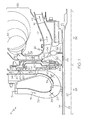
- FIG. 1 is a simplified schematic illustration of an exemplary gas turbine engine (partially shown) including an axially-split radial turbine, as illustrated in accordance with an exemplary embodiment of the present invention
- FIG. 2 is an isometric view of the axially-split radial turbine illustrated in FIG. 1 ;
- FIG. 3 is a cross-sectional view of a portion of the axially-split radial turbine, as taken along line 3-3 identified in FIG. 2 ;
- FIG. 4 is a cross-sectional view of an alternative embodiment of an axially-split radial turbine
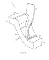
- FIG. 5 is an isometric view of an exemplary bladed piece
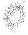
- FIG. 6 is a monolithic blade ring formed from a plurality of bladed pieces as shown in FIG. 5 ;
- FIG. 7 is an isometric view of an exemplary rotor disk for bonding to the monolithic blade ring of FIG. 6 .
- FIG. 1 is a simplified cross-sectional view of a portion of a gas turbine engine (GTE) 18 including an internally-cooled, axially-split radial turbine 20, as illustrated in accordance with an exemplary embodiment of the present invention.
- GTE 18 is offered by way of example only to provide a convenient and non-limiting context in which an exemplary embodiment of radial turbine 20 can be described.
- embodiments of axially-split radial turbine 20 can be employed within various types of gas turbine engines including, but not limited to, other types of turbofan, turboprop, turboshaft, and turbojet engines, whether deployed onboard an aircraft, watercraft, or ground vehicle (e.g., a tank), included within an auxiliary power unit, included within industrial power generators, or utilized within another platform or application.
- gas turbine engines including, but not limited to, other types of turbofan, turboprop, turboshaft, and turbojet engines, whether deployed onboard an aircraft, watercraft, or ground vehicle (e.g., a tank), included within an auxiliary power unit, included within industrial power generators, or utilized within another platform or application.
- GTE 18 is illustrated as a two spool engine including a low pressure (LP) shaft 22 and a high pressure (HP) shaft 24.
- LP shaft 22 and HP shaft 24 are co-axial; that is, LP shaft 22 extends through a longitudinal channel provided through HP shaft 24 along a rotational axis 26.
- GTE 18 further includes a compressor section 28, a combustion section 30, and a turbine section 32, each of which is only partially shown in FIG. 1 .
- An HP compressor 29 is included within compressor section 28 and mounted to the upstream or forward end of HP shaft 24.
- Radial turbine 20, which is contained within turbine section 32, is mounted to the opposing, aft end of HP shaft 24 as the HP turbine.
- compressor section 28 and turbine section 32 may further include an LP compressor and an LP turbine, respectively, which may be mounted to opposing ends of LP shaft 22.
- airflow is received from a non-illustrated intake section included within GTE 18 and supplied to compressor section 28.
- a compressor section duct 36 guides the pressurized airflow through HP compressor 29, which further compresses the airflow prior to discharge into combustion section 30.
- the compressed airflow is directed into a combustion chamber (not shown) included within combustion section 30, mixed with fuel, and ignited to produce combustive gasses.
- the combustive gasses expand rapidly, exit combustion section 30 through a turbine scroll 40, and are directed through a duct 27 radial turbine 20.
- the combustive gas flow drives rotation of radial turbine 20, which drives further rotation of HP shaft 24 and HP compressor 29.
- a turbine section duct 42 directs the combustive gas flow into a turbine nozzle ring 44 (indicated in FIG. 1 by arrows 46).
- Turbine nozzle ring 44 accelerates the combustive gas flow and imparts the gas flow with a desired tangential component prior to reaching an LP turbine (not shown), which is positioned downstream of nozzle ring 44 and mounted to the aft end of LP shaft 22.
- the combustive gas flow drives the rotation of the non-illustrated LP turbine, which drives further rotation of the LP turbine and LP shaft 22.
- shafts 22 and 24 provide power output, which may be utilized in a variety of different manners, depending upon whether GTE 18 assumes the form of a turbofan, turboprop, turboshaft, turbojet engine, or an auxiliary power unit, to list but a few examples.
- the combustive gas flow is then mixed with cooler bypass flow and exhausted from GTE 18.
- the combustive gas flow may be exhausted through a propulsion nozzle to provide forward thrust.
- radial turbine 20 is internally cooled and axially split; that is, fabricated from at least two discrete portions, which are separated along a plane orthogonal to rotational axis 26 and which are assembled to produce a completed turbine.
- radial turbine 20 includes two halves: a forward turbine rotor 50, and an aft turbine rotor 52.
- forward turbine rotor 50 and the forward face of aft turbine rotor 52 abut along a generally annular interface, which resides within the plane generally orthogonal to rotational axis 26 and which is referred to herein as "split line 54."
- Forward turbine rotor 50 and aft turbine rotor 52 can be metallurgically bonded utilizing, for example, soldering, brazing, or diffusion bonding.
- forward turbine rotor 50 and aft turbine rotor 52 are assembled as discrete, non-bonded pieces, which are maintained in engagement utilizing mechanical means, as opposed to metallurgical bonding.
- mechanical means generally refers to an engagement of a first and a second component by a third component through the application of force.
- forward turbine rotor 50 and aft turbine rotor 52 may be clamped together utilizing, for example, a tie shaft or curvic (not shown).
- a plurality of bolts or other such fasteners may be employed for such engagement.
- radial turbine 20 offers several advantages not provided by conventional one piece or monolithic turbines, whether axial or radial, and specifically overcomes several disadvantages associated with monolithic radial turbines.
- fabrication e.g., casting and machining
- components can be cast having more complex internal geometries thereby facilitating fabrication of components having internal cooling passages.
- the multi-piece construction of radial turbine 20 facilitates the formation of internal voids within the central disk of turbine 20, whether created as cast-in features or through strategic removal of material. As a result, the overall mass of radial turbine 20 can be favorably reduced.
- the disk of radial turbine 20 can be fabricated to include an internal cooling circuit, which may supply relatively cool airflow to the internal cooling passages formed within the turbine blades, as described more fully below.
- the axially-split design of radial turbine 20 enables forward turbine rotor 50 and an aft turbine rotor 52 to be fabricated from disparate materials tailored to the disparate operating conditions experienced by the aft and forward sections of rotor 52 during operation, as still further described below.
- the axially-split design of the radial turbine allows the two halves of the blades to be thermally independent which results in reduction in blade thermal stresses.
- FIG. 2 is an isometric view of radial turbine 20, and FIG. 3 is a cross-sectional view of a portion of radial turbine 20, as taken along line 3-3 identified in FIG. 2 .
- forward turbine rotor 50 includes a forward hub section 56 and a plurality of forward blade segments 58 (i.e., inducer blade segments), which are circumferentially spaced around and extend radially outward from hub section 56.
- Aft turbine rotor 50 likewise includes an aft hub section 60 and a plurality of aft blade segments 62 (i.e., exducer blade segments), which are circumferentially spaced around and extend radially outward from hub section 60.
- Bond lines 51a and 51b illustrate the bonding region between forward hub section 56 and blades segments 58, and aft hub section 60 and blade segments 62, as will be described in greater detail below.
- Forward blade segments 58 and aft blade segments 62 are shown in FIG. 3 in cutaway through the blade segments to illustrate various internal cooling features 65, 67, such as internal cooling channels, slots, apertures, and the like, which may be formed in blade segments 58 and/or blade segments 62 and as are known in the art.
- FIG. 3 is not a truly planar cross-section of the turbine, but rather follows the curvature of the blade segments 58 and 62.
- Forward hub section 56 and aft hub section 60 assume the form of generally annular bodies having central openings 64 and 66 therein, respectively, as identified in FIG. 3 .
- the inner diameter of central opening 64 provided through forward hub section 56 is generally equivalent to the inner diameter of central opening 66 provided through aft hub section 60.
- forward hub section 56 aligns axially with aft hub section 60 and, preferably, radially pilots thereto.
- a radially-overlapping hub interface (e.g., an annular lap joint) may be provided between forward hub section 56 and aft hub section 60 to radially pilot hub section 56 to forward hub section 60.
- hub sections 56 and 60 combine to form a central hub 56, 60 when radial turbine 20 is assembled.
- Central openings 64 and 66 likewise align when radial turbine 20 is assembled to define a central opening 64, 66 through radial turbine 20.
- blade segments 58 and 62 combine to form a contiguous turbine blade 58, 62.
- a spool e.g., high pressure shaft 24 of GTE 18
- Radial turbine 20 is fixedly mounted to the gas turbine engine spool utilizing, for example, a curvic-type attachment.
- forward blade segments 58 align axially with aft blade segments 62.
- Forward blade segments 58 and aft blade segments 62 abut and, in certain cases, may interlock.
- Axial alignment of forward blade segments 58 and aft blade segments 62 may also be maintained by an axial clamping force or pre-load exerted on radial turbine 20 by a tie-shaft (not shown).
- the mating interface between forward hub section 56 and aft hub section 60 may be fabricated to include one or more alignment features (e.g., keys, teeth, or castellations).
- radial turbine 20 When assembled, radial turbine 20 provides substantially uninterrupted airflow guidance surfaces along the blade passage and, specifically, when transitioning from forward hub section 56 and aft hub section 60, to minimize leakage of the compressed airflow between sections 56 and 60. In so doing, axially-split radial turbine 20 achieves aerodynamic performance levels substantially equivalent to that provided by a radial turbine having a unitary or monolithic construction.
- axially-split radial turbine 20 can be readily fabricated to include at least one inner disk cavity 68, 70 (shown in FIG. 3 ) for mass reduction and/or for cooling purposes.
- material may be removed from the back or trailing face of forward hub section 56 to form a first annular cavity or groove 68 therein.
- material may be removed from the front or leading face of aft hub section 60 to form a second annular cavity or groove 70 therein.
- annular cavity 68, 70 When radial turbine 20 is assembled, the trailing face of forward turbine rotor 50 is positioned adjacent the leading face of aft turbine rotor 52, and grooves 68 and 70 cooperate to define an annular cavity 68, 70 within radial turbine 20. Inner annular cavity 68, 70 is fully contained within radial turbine 20. Consequently, the provision of annular cavity 68, 70 has minimal impact on the overall structural integrity of radial turbine 20.
- a plurality of discrete, circumferentially-spaced cavities can be formed within radial turbine 20 as opposed to a continuous annular cavity.
- grooves 68 and 70 can be fabricated as integral cast-in features.
- the creation of an internal cavity or cavities within radial turbine 20 facilitates the formation the hub cooling passages through central hub 56, 60 of radial turbine 20, as described below.
- axially-split radial turbine 20 is fabricated to include a plurality of hub cooling air passages 72 (one of which is shown in FIG. 3 ).
- cooling passages 72 each extend radially through turbine central hub 56, 60 to fluidly couple the external hub flow paths to the interior of turbine hub 56, 60 and, specifically, to annular cavity 68, 70.
- Each hub cooling passage 72 includes an inlet 76 and an outlet 74, which are formed in the respective inner and outer circumferential surfaces of hub 56, 60. Outlet 74 is fluidly coupled to annular cavity 68, 70.
- Annular cavity 68, 70 may be, in turn, fluidly coupled to the inlet or inlets of one or more cooling flow passages formed within forward blade segments 58 and/or aft blade segments 62.
- annular cavity 68, 70 may be fluidly coupled to the inlet of a first flow passage 65 formed within each forward blade segment 58 and to the inlet of a second flow passage 67 formed within each aft blade segment 62.
- airflow may be bled from a section of the engine upstream of combustion section 30; e.g., as indicated in FIG.
- a portion of the airflow flowing within compressor section duct 36 may be diverted into outlet 82 of a combustion bypass conduit 84.
- a portion of this cooler bypass airflow may be directed via an aperture in the conduit toward the leading edge of forward hub section 56 to provide saddle region cooling (indicated in FIG. 1 by arrow 86), while the remainder other bypass air (indicated by arrow 88) may be directed radially inward toward the engine centerline, flow axially along HP shaft 24, and may ultimately flow into inlet 76 of hub cooling air passages 72 to provide cooling of hub 56, 60, and blade segments 58 and 62 (indicated in FIG. 1 by arrows 88).
- cooling air flow 88 may be turbulated prior to entering HP shaft 24. Turbulating features may be machined or cut into the turbine rotor prior to the region where the cooling air flows into HP shaft 24 (not shown).
- FIG. 4 discloses an alternative cooling scheme as compared to that of FIGs. 1 and 3 .
- a sleeve 81 underneath shaft 24 is provided with a plurality of turbulating features 83 to turbulate the cooling air 88 prior to its entry into cooling passage 72.
- forward turbine rotor 50 and aft turbine rotor 52 can be fabricated from disparate materials tailored to the disparate operating conditions experienced by the aft and fore sections of rotor 50, 52.
- forward turbine rotor 50 may be fabricated from a metal or alloy, such as a nickel-based superalloy, having a relatively high density and thermal tolerance.
- aft turbine rotor 52 may be fabricated from a metal or alloy having a lower thermal tolerance (e.g., a titanium-based superalloy) and a lower density.
- turbine 20 can be maximized to improve various measures of engine performance (e.g., specific fuel consumption and power density), while the overall weight of turbine 20 is reduced as compared a monolithic or single piece impeller fabricated entirely from a heavier superalloy having higher thermal tolerances.
- measures of engine performance e.g., specific fuel consumption and power density
- Criteria other than relative densities and thermal tolerances may be utilized to select the material or materials from which aft turbine rotor 52 and forward turbine rotor 50 are fabricated.
- turbine rotor 50 may be fabricated from a material having a relatively high mechanical strength to decrease the likelihood of crack formation and propagation, and improve creep resistance, during high speed operation of turbine 20.
- turbine rotors 50 and 52 may be fabricated from the same or similar alloy, but subjected to different process steps (forged and/or heat treated differently) to tailor material properties (e.g., grain sizes) to the particular conditions to which the individual pieces are subjected.
- a ring of blade structures 58 and 62 may be formed by metallurgical bonding a series of bladed pieces together.
- bladed piece denotes any structural element or assemblage of structural elements at least a portion of which has a generally arc-shaped or curved geometry and which are able to be arranged in a partial or complete ring formation with a number of like bladed pieces.
- Each bladed piece will typically include a wedge-shaped shank from which one or more turbine or compressor blades radially project.
- FIG. 5 presents an isometric view of an exemplary bladed piece 94.
- bladed piece 94 includes a wedge-shaped body or shank 96 and a blade 98 extending radially therefrom.
- Shank 96 has been cast or otherwise fabricated to include an outer sacrificial portion that envelops or encompasses the desired shape of the completed shank. Stated differently, shank 96 is a rough casting or preform physically embodying the finished shank, which may be subsequently defined by further machining. Shank 96 includes a forward shoulder 100 and an aft shoulder 102, which extend from the central body of shank 96 in opposing axial directions. Opposing axial shoulders 100 and 102 are fabricated to include outer tooling contact surfaces 104 and 106, respectively, which are located axially adjacent the forward and aft ends of blade 98 and which have a gently curved or arced outer geometry.
- Shank 96 also includes opposing lateral faces or sidewall surfaces 108, only one of which can be seen in FIG. 5 .
- Sidewall surfaces 108 are each angled to impart shank 96 with a wedge-shaped geometry, when viewed from the forward/leading or aft/trailing end thereof. As each sidewall surface 108 of shank 96 will ultimately be bonded to a corresponding sidewall surface of a neighboring shank, sidewall surfaces 108 are referred to herein as "shank-to-shank bonding surfaces 108.”
- the bladed pieces 94 are ideally fabricated from an oxidation-resistant material having good mechanical strength at high temperatures.
- the bladed pieces 94 may be purchased from a supplier or independently fabricated by, for example, individually casting and machining each bladed piece.
- each bladed piece 94 is cast from a single crystal superalloy having its crystallographic grain structure oriented to provide optimal mechanical strength in a radial direction.
- an oxidation-resistant, single crystal, nickel-based superalloy may be utilized, such as the nickel-based superalloy commercially identified as "CMSX 4."
- CMSX 4 nickel-based superalloy commercially identified as "CMSX 4.”
- the bladed pieces 94 may be fabricated from other high temperature materials, as well, including equiaxed superalloys.
- the initial fabrication of a plurality of bladed pieces which are subsequently joined or consolidated into a monolithic bladed ring utilizing a directed thermal growth bonding process of the type described bellow, provides several advantages as compared to single shot casting processes.
- any defective or otherwise unusable pieces can be identified prior to consolidation; consequently, scrap volume and cost can be greatly reduced as compared to a single shot casting process wherein any voiding, occlusions, or other defects may require rejection of the entire ring casting.
- casting can typically be more reliably and precisely controlled for smaller volume pieces; thus, casting individual bladed pieces generally allows for higher yields due to more reliable filling of the individual bladed pieces and the production of bladed pieces having relatively complex external and internal features, such as internal cooling passages.
- Bladed pieces 94 are inter-bonded to yield the monolithic bladed ring 150, as shown in FIG. 6 , utilizing a metallurgical bonding process, such as diffusion bonding or brazing.
- the monolithic bladed ring 150 may be bonded to a rotor disk (such as may form hub sections 56 or 60) to produce a turbine rotor, such as either of turbine rotors 50 or 52 shown in FIGs. 1 and 3 .
- Bond lines 51a and 51b illustrate such bonding location and orientation with regard to the forward turbine rotor 50 and the aft turbine rotor 52, respectively.
- the interior of the monolithic bladed ring 150 may be machined to generally conform with the separately-fabricated rotor disk, which is described below in conjunction with FIG. 7 .
- FIG. 7 is an isometric view of an exemplary rotor disk 160.
- Rotor disk 160 is preferably fabricated from an alloy tailored to the unique operational environment of the rotor disk; e.g., an alloy having relatively high stress rupture and life cycle fatigue properties.
- rotor disk 160 is fabricated from an oxidation-resistant, nickel-based superalloy; while monolithic bladed ring 150 is fabricated from a single crystal superalloy of the type described above.
- the outer annular portion of rotor disk 160 may be machined to impart disk 160 with a desired surface finish and an outer diameter approximately equivalent to the inner diameter of machined airfoil ring 150.
- Machined monolithic bladed ring 150 is then fit onto machined rotor disk 160.
- the leading and trailing annular interfaces between the outer circumference of ring 150 and the inner circumference of disk 160 are sealed by, for example, brazing to prevent the ingress of air into the ring-disk interface that may otherwise interfere bonding.
- a HIP diffusion bonding process or other directed thermal growth bonding process is then carried-out to bond monolithic bladed ring 150 to rotor disk 160 and thereby yield a metallurgically-bonded turbine rotor, such as either of turbine rotors 50 or 52 shown in FIG. 3 .
- an axially-split, internally-cooled radial turbine that provides both a mechanical and a cooling advantage to manage disk stresses.
- traditional radial turbine stresses occur in the bore, the saddle, and the blade mid-chord.
- a hole in the bore to accommodate the turbine shaft further increases bore stress.
- Increasing rotational speed and operating temperatures for improved performance further increases all stresses in the turbine.
- the presently described split radial design manages bore stresses by reducing the disk rim-to-bore thermal gradient, which contributes upwards of 50% of the bore stress.
- the embodiments of the present disclosure have the benefits of eliminating the aforementioned blade mid-chord stress problems completely. That is, the saddle region stresses are managed by direct cooling with impingement air from the combustor bypass flow plus indirect cooling by conduction to the blade cooling passages.
Landscapes
- Engineering & Computer Science (AREA)
- Mechanical Engineering (AREA)
- General Engineering & Computer Science (AREA)
- Turbine Rotor Nozzle Sealing (AREA)
Abstract
Description
- The present invention relates generally to gas turbine engines and, more particularly, to axially-split radial turbines for usage within gas turbine engines.
- Gas turbine engines ("GTE") have been engineered extensively to improve efficiency, thrust-to-weight ratios, and other measures of engine performance. One of the most direct manners by which engine performance can be improved is through increases in the core rotational speeds and turbine inlet temperatures generated during engine operation. However, as turbine inlet temperatures and rotational speeds increase, so too do the thermal and mechanical demands placed on the GTE components. The most demanding performance requirements are typically placed on the high pressure turbine rotor or rotors, which are positioned immediately downstream of the GTE combustion section and which rotate at the greatest speed during engine operation. The turbine blades, in particular, are directly exposed to combustive gas flow at or near peak temperatures and are consequently heated to exceedingly high temperatures at which most alloys weaken or melt and become prone to oxidation or other forms of chemical degradation. By comparison, the inner portion of the turbine (commonly referred to as the "turbine disk") is largely shielded from direct exposure to combustive gas flow, but is subject to considerable mechanical stress resulting from the centrifugal forces acting on the turbine rotor at high rotational speeds.
- Turbines can be broadly divided into two categories, axial and radial turbines, based upon the direction of airflow received by the turbine relative to the turbine's rotational axis. Relative to axial turbines, radial turbines offer certain performance benefits including decreased thermal and mechanical stresses, which enable the turbine to operate at greater efficiencies and at higher temperatures. However, due to the nature of their design, radial turbines are relatively lengthy in the axial direction. As a result, a radial turbine can be undesirably heavy and cumbersome. Axial turbines can readily be cooled, which allows such turbines to operate at high inlet temperature, while despite the proposal of multiple cooled radial turbine concepts, there are no cooled radial turbines currently implemented in commercial gas turbine engine platforms. As a result, majority of gas-turbine engine employing radial turbine are operating at much lower turbine inlet temperature relative to those employing an axial turbine. In addition, it is often difficult to fabricate radial turbines utilizing conventional casting processes, especially if such radial turbines include relatively complex internal cooling flow passages. Still further, present blade cooling schemes are unable to adequately cool the blade tip and the "saddle" region (between blades) of the turbine, resulting in undesirable high component metal operating temperatures and temperature gradients, especially during start-up conditions. For at least these reasons, and despite the proposal of multiple radial turbine designs in the prior art, few currently-implemented gas turbine engine platforms incorporate radial turbines.
- It would thus be desirable to provide a radial turbine suitable for usage in a gas turbine engine that is relatively lightweight and cost effective to manufacture and implement, can operate at elevated turbine inlet temperature levels, and that has improved blade tip and saddle region cooling characteristics. Other desirable features and characteristics of embodiments of the present invention will become apparent from the subsequent Detailed Description and the appended Claims, taken in conjunction with the accompanying drawings and the foregoing Background.
- Embodiments of an axially-split radial turbine are provided. In one embodiment, the axially-split radial turbine includes a forward rotor section and an aft rotor section being mechanically and abuttingly coupled to one another along an annular interface that resides within a plane generally orthogonal to a rotational axis of the axially-split radial turbine.
- In another embodiment, the axially-split radial turbine includes a forward rotor section and an aft rotor section being mechanically and abuttingly coupled to one another along an annular interface that resides within a plane generally orthogonal to a rotational axis of the axially-split radial turbine, an inner annular cavity fully defined within the axially-split radial turbine, and a tie shaft for abuttingly coupling the forward rotor section to the aft rotor section. The forward rotor section comprises a forward blade segment and a forward hub section metallurgically bonded together along a first bond line and wherein the aft rotor section comprises an aft blade segment and an aft hub section metallurgically bonded together along a second bond line. When the forward rotor section and the aft rotor section are coupled to one another, the forward blade segment and the aft blade segment define a contiguous radial turbine blade. Furthermore, the forward hub section defines a first annular cavity groove and wherein the aft hub section defines a second annular cavity groove, wherein when the forward rotor section and the aft rotor section are coupled to one another, the first and second annular grooves define the inner annual cavity.
- In yet another embodiment, an axially-split radial turbine is provided as part of a gas turbine engine. The axially-split radial turbine as part of the gas turbine engine includes a forward rotor section and an aft rotor section being mechanically and abuttingly coupled to one another along an annular interface that resides within a plane generally orthogonal to a rotational axis of the axially-split radial turbine.
- At least one example of the present invention will hereinafter be described in conjunction with the following figures, wherein like numerals denote like elements, and wherein:
-
FIG. 1 is a simplified schematic illustration of an exemplary gas turbine engine (partially shown) including an axially-split radial turbine, as illustrated in accordance with an exemplary embodiment of the present invention; -
FIG. 2 is an isometric view of the axially-split radial turbine illustrated inFIG. 1 ; -
FIG. 3 is a cross-sectional view of a portion of the axially-split radial turbine, as taken along line 3-3 identified inFIG. 2 ; -
FIG. 4 is a cross-sectional view of an alternative embodiment of an axially-split radial turbine; -
FIG. 5 is an isometric view of an exemplary bladed piece; -
FIG. 6 is a monolithic blade ring formed from a plurality of bladed pieces as shown inFIG. 5 ; and -
FIG. 7 is an isometric view of an exemplary rotor disk for bonding to the monolithic blade ring ofFIG. 6 . - The following Detailed Description is merely exemplary in nature and is not intended to limit the invention or the application and uses of the invention. Furthermore, there is no intention to be bound by any theory presented in the preceding Background or the following Detailed Description.
-
FIG. 1 is a simplified cross-sectional view of a portion of a gas turbine engine (GTE) 18 including an internally-cooled, axially-splitradial turbine 20, as illustrated in accordance with an exemplary embodiment of the present invention. As illustrated inFIG. 1 and described herein, GTE 18 is offered by way of example only to provide a convenient and non-limiting context in which an exemplary embodiment ofradial turbine 20 can be described. It will be readily appreciated that embodiments of axially-splitradial turbine 20 can be employed within various types of gas turbine engines including, but not limited to, other types of turbofan, turboprop, turboshaft, and turbojet engines, whether deployed onboard an aircraft, watercraft, or ground vehicle (e.g., a tank), included within an auxiliary power unit, included within industrial power generators, or utilized within another platform or application. - In the exemplary embodiment shown in
FIG. 1 , GTE 18 is illustrated as a two spool engine including a low pressure (LP)shaft 22 and a high pressure (HP)shaft 24.LP shaft 22 and HPshaft 24 are co-axial; that is,LP shaft 22 extends through a longitudinal channel provided throughHP shaft 24 along arotational axis 26. GTE 18 further includes acompressor section 28, acombustion section 30, and aturbine section 32, each of which is only partially shown inFIG. 1 . An HPcompressor 29 is included withincompressor section 28 and mounted to the upstream or forward end of HPshaft 24.Radial turbine 20, which is contained withinturbine section 32, is mounted to the opposing, aft end ofHP shaft 24 as the HP turbine. Although not shown inFIG. 1 for clarity,compressor section 28 andturbine section 32 may further include an LP compressor and an LP turbine, respectively, which may be mounted to opposing ends ofLP shaft 22. - During engine operation, airflow is received from a non-illustrated intake section included within GTE 18 and supplied to
compressor section 28. As indicated inFIG. 1 byarrows 34, acompressor section duct 36 guides the pressurized airflow through HPcompressor 29, which further compresses the airflow prior to discharge intocombustion section 30. The compressed airflow is directed into a combustion chamber (not shown) included withincombustion section 30, mixed with fuel, and ignited to produce combustive gasses. As indicated inFIG. 1 byarrows 38, the combustive gasses expand rapidly,exit combustion section 30 through aturbine scroll 40, and are directed through aduct 27radial turbine 20. The combustive gas flow drives rotation ofradial turbine 20, which drives further rotation of HPshaft 24 and HPcompressor 29. After flowing throughradial turbine 20, aturbine section duct 42 directs the combustive gas flow into a turbine nozzle ring 44 (indicated inFIG. 1 by arrows 46).Turbine nozzle ring 44 accelerates the combustive gas flow and imparts the gas flow with a desired tangential component prior to reaching an LP turbine (not shown), which is positioned downstream ofnozzle ring 44 and mounted to the aft end ofLP shaft 22. The combustive gas flow drives the rotation of the non-illustrated LP turbine, which drives further rotation of the LP turbine andLP shaft 22. Collectively, the rotation ofshafts - As indicated above,
radial turbine 20 is internally cooled and axially split; that is, fabricated from at least two discrete portions, which are separated along a plane orthogonal torotational axis 26 and which are assembled to produce a completed turbine. In the exemplary embodiment illustrated inFIG. 1 , specifically,radial turbine 20 includes two halves: aforward turbine rotor 50, and anaft turbine rotor 52. The aft face offorward turbine rotor 50 and the forward face ofaft turbine rotor 52 abut along a generally annular interface, which resides within the plane generally orthogonal torotational axis 26 and which is referred to herein as "split line 54."Forward turbine rotor 50 andaft turbine rotor 52 can be metallurgically bonded utilizing, for example, soldering, brazing, or diffusion bonding. However, in preferred embodiment,forward turbine rotor 50 andaft turbine rotor 52 are assembled as discrete, non-bonded pieces, which are maintained in engagement utilizing mechanical means, as opposed to metallurgical bonding. As used herein, the term "mechanical means" generally refers to an engagement of a first and a second component by a third component through the application of force. For example,forward turbine rotor 50 andaft turbine rotor 52 may be clamped together utilizing, for example, a tie shaft or curvic (not shown). Alternatively, a plurality of bolts or other such fasteners (not shown) may be employed for such engagement. - The axially-split design of
radial turbine 20 offers several advantages not provided by conventional one piece or monolithic turbines, whether axial or radial, and specifically overcomes several disadvantages associated with monolithic radial turbines. First, by assemblingradial turbine 20 from multiple pieces, fabrication (e.g., casting and machining) of the turbine pieces can be enhanced. In particular, by reducing casting volume, components can be cast having more complex internal geometries thereby facilitating fabrication of components having internal cooling passages. Second, the multi-piece construction ofradial turbine 20 facilitates the formation of internal voids within the central disk ofturbine 20, whether created as cast-in features or through strategic removal of material. As a result, the overall mass ofradial turbine 20 can be favorably reduced. Additionally, the disk ofradial turbine 20 can be fabricated to include an internal cooling circuit, which may supply relatively cool airflow to the internal cooling passages formed within the turbine blades, as described more fully below. Third, the axially-split design ofradial turbine 20 enables forwardturbine rotor 50 and anaft turbine rotor 52 to be fabricated from disparate materials tailored to the disparate operating conditions experienced by the aft and forward sections ofrotor 52 during operation, as still further described below. Fourth, the axially-split design of the radial turbine allows the two halves of the blades to be thermally independent which results in reduction in blade thermal stresses. -
FIG. 2 is an isometric view ofradial turbine 20, andFIG. 3 is a cross-sectional view of a portion ofradial turbine 20, as taken along line 3-3 identified inFIG. 2 . As can be seen inFIGs. 2 and3 ,forward turbine rotor 50 includes aforward hub section 56 and a plurality of forward blade segments 58 (i.e., inducer blade segments), which are circumferentially spaced around and extend radially outward fromhub section 56.Aft turbine rotor 50 likewise includes anaft hub section 60 and a plurality of aft blade segments 62 (i.e., exducer blade segments), which are circumferentially spaced around and extend radially outward fromhub section 60.Bond lines forward hub section 56 andblades segments 58, andaft hub section 60 andblade segments 62, as will be described in greater detail below.Forward blade segments 58 andaft blade segments 62 are shown inFIG. 3 in cutaway through the blade segments to illustrate various internal cooling features 65, 67, such as internal cooling channels, slots, apertures, and the like, which may be formed inblade segments 58 and/orblade segments 62 and as are known in the art. As such, it will be appreciated by those skilled in the art thatFIG. 3 is not a truly planar cross-section of the turbine, but rather follows the curvature of theblade segments -
Forward hub section 56 andaft hub section 60 assume the form of generally annular bodies havingcentral openings FIG. 3 . In the illustrated example shown inFIGs. 1 and3 , the inner diameter ofcentral opening 64 provided throughforward hub section 56 is generally equivalent to the inner diameter ofcentral opening 66 provided throughaft hub section 60. Whenradial turbine 20 is assembled,forward hub section 56 aligns axially withaft hub section 60 and, preferably, radially pilots thereto. Although not shown inFIGs. 1 and3 for clarity, a radially-overlapping hub interface (e.g., an annular lap joint) may be provided betweenforward hub section 56 andaft hub section 60 to radiallypilot hub section 56 to forwardhub section 60. In this manner,hub sections central hub radial turbine 20 is assembled.Central openings radial turbine 20 is assembled to define acentral opening radial turbine 20. Further,blade segments contiguous turbine blade radial turbine 20 is installed within GTE 18 (FIG. 1 ), a spool (e.g.,high pressure shaft 24 of GTE 18) extends through this longitudinal channel.Radial turbine 20 is fixedly mounted to the gas turbine engine spool utilizing, for example, a curvic-type attachment. - When axially-split
radial turbine 20 is assembled,forward blade segments 58 align axially withaft blade segments 62.Forward blade segments 58 andaft blade segments 62 abut and, in certain cases, may interlock. Axial alignment offorward blade segments 58 andaft blade segments 62 may also be maintained by an axial clamping force or pre-load exerted onradial turbine 20 by a tie-shaft (not shown). Additionally, the mating interface betweenforward hub section 56 andaft hub section 60 may be fabricated to include one or more alignment features (e.g., keys, teeth, or castellations). As a result of this structural configuration, neighboring pairs offorward blade segments 58 andaft blade segments 62 cooperate to formcontiguous blade structures radial turbine 20 provides substantially uninterrupted airflow guidance surfaces along the blade passage and, specifically, when transitioning fromforward hub section 56 andaft hub section 60, to minimize leakage of the compressed airflow betweensections radial turbine 20 achieves aerodynamic performance levels substantially equivalent to that provided by a radial turbine having a unitary or monolithic construction. - By virtue of its multi-piece construction, axially-split
radial turbine 20 can be readily fabricated to include at least oneinner disk cavity 68, 70 (shown inFIG. 3 ) for mass reduction and/or for cooling purposes. For example, as indicated inFIGs. 1 and3 , material may be removed from the back or trailing face offorward hub section 56 to form a first annular cavity orgroove 68 therein. Similarly, material may be removed from the front or leading face ofaft hub section 60 to form a second annular cavity orgroove 70 therein. Whenradial turbine 20 is assembled, the trailing face offorward turbine rotor 50 is positioned adjacent the leading face ofaft turbine rotor 52, andgrooves annular cavity radial turbine 20. Innerannular cavity radial turbine 20. Consequently, the provision ofannular cavity radial turbine 20. In further embodiments, a plurality of discrete, circumferentially-spaced cavities can be formed withinradial turbine 20 as opposed to a continuous annular cavity. In further embodiments,grooves radial turbine 20 facilitates the formation the hub cooling passages throughcentral hub radial turbine 20, as described below. - With continued reference to
FIGs. 1 and3 , and as shown most clearly inFIG. 3 , axially-splitradial turbine 20 is fabricated to include a plurality of hub cooling air passages 72 (one of which is shown inFIG. 3 ). As shown inFIGs. 1 and3 , coolingpassages 72 each extend radially through turbinecentral hub turbine hub annular cavity hub cooling passage 72 includes aninlet 76 and anoutlet 74, which are formed in the respective inner and outer circumferential surfaces ofhub Outlet 74 is fluidly coupled toannular cavity Annular cavity forward blade segments 58 and/oraft blade segments 62. For example, as shown inFIG. 3 ,annular cavity first flow passage 65 formed within eachforward blade segment 58 and to the inlet of asecond flow passage 67 formed within eachaft blade segment 62. During operation of GTE 18 (FIG. 1 ), airflow may be bled from a section of the engine upstream ofcombustion section 30; e.g., as indicated inFIG. 1 byarrows 80, a portion of the airflow flowing withincompressor section duct 36 may be diverted intooutlet 82 of a combustion bypass conduit 84. A portion of this cooler bypass airflow may be directed via an aperture in the conduit toward the leading edge offorward hub section 56 to provide saddle region cooling (indicated inFIG. 1 by arrow 86), while the remainder other bypass air (indicated by arrow 88) may be directed radially inward toward the engine centerline, flow axially alongHP shaft 24, and may ultimately flow intoinlet 76 of hub coolingair passages 72 to provide cooling ofhub blade segments 58 and 62 (indicated inFIG. 1 by arrows 88). (In an alternative embodiment, a TOBI system that processes compressor discharge air may be employed to provide cooling air). In some embodiments, the coolingair flow 88 may be turbulated prior to enteringHP shaft 24. Turbulating features may be machined or cut into the turbine rotor prior to the region where the cooling air flows into HP shaft 24 (not shown). -
FIG. 4 discloses an alternative cooling scheme as compared to that ofFIGs. 1 and3 . In the embodiment ofFIG. 4 , asleeve 81 underneathshaft 24 is provided with a plurality of turbulating features 83 to turbulate the coolingair 88 prior to its entry into coolingpassage 72. - As noted above,
forward turbine rotor 50 andaft turbine rotor 52 can be fabricated from disparate materials tailored to the disparate operating conditions experienced by the aft and fore sections ofrotor turbine rotor 50 is exposed will typically be significantly higher than the temperatures to whichaft turbine rotor 52 is exposed,forward turbine rotor 50 may be fabricated from a metal or alloy, such as a nickel-based superalloy, having a relatively high density and thermal tolerance. In contrast,aft turbine rotor 52 may be fabricated from a metal or alloy having a lower thermal tolerance (e.g., a titanium-based superalloy) and a lower density. In this manner, the temperature capabilities ofturbine 20 can be maximized to improve various measures of engine performance (e.g., specific fuel consumption and power density), while the overall weight ofturbine 20 is reduced as compared a monolithic or single piece impeller fabricated entirely from a heavier superalloy having higher thermal tolerances. - Criteria other than relative densities and thermal tolerances may be utilized to select the material or materials from which
aft turbine rotor 52 andforward turbine rotor 50 are fabricated. For example, as mechanical stress arising from centrifugal forces will typically concentrate inforward turbine rotor 50,turbine rotor 50 may be fabricated from a material having a relatively high mechanical strength to decrease the likelihood of crack formation and propagation, and improve creep resistance, during high speed operation ofturbine 20. Additionally,turbine rotors - In some embodiments, a ring of
blade structures FIG. 5 presents an isometric view of an exemplarybladed piece 94. In this particular example,bladed piece 94 includes a wedge-shaped body orshank 96 and ablade 98 extending radially therefrom.Shank 96 has been cast or otherwise fabricated to include an outer sacrificial portion that envelops or encompasses the desired shape of the completed shank. Stated differently,shank 96 is a rough casting or preform physically embodying the finished shank, which may be subsequently defined by further machining.Shank 96 includes aforward shoulder 100 and anaft shoulder 102, which extend from the central body ofshank 96 in opposing axial directions. Opposingaxial shoulders blade 98 and which have a gently curved or arced outer geometry.Shank 96 also includes opposing lateral faces or sidewall surfaces 108, only one of which can be seen inFIG. 5 . Sidewall surfaces 108 are each angled to impartshank 96 with a wedge-shaped geometry, when viewed from the forward/leading or aft/trailing end thereof. As eachsidewall surface 108 ofshank 96 will ultimately be bonded to a corresponding sidewall surface of a neighboring shank, sidewall surfaces 108 are referred to herein as "shank-to-shank bonding surfaces 108." - The
bladed pieces 94 are ideally fabricated from an oxidation-resistant material having good mechanical strength at high temperatures. Thebladed pieces 94 may be purchased from a supplier or independently fabricated by, for example, individually casting and machining each bladed piece. In a preferred embodiment, eachbladed piece 94 is cast from a single crystal superalloy having its crystallographic grain structure oriented to provide optimal mechanical strength in a radial direction. By way of non-limiting example, an oxidation-resistant, single crystal, nickel-based superalloy may be utilized, such as the nickel-based superalloy commercially identified as "CMSX 4." This notwithstanding, thebladed pieces 94 may be fabricated from other high temperature materials, as well, including equiaxed superalloys. Whether fabricated from a single crystal or an equiaxed alloy, the initial fabrication of a plurality of bladed pieces, which are subsequently joined or consolidated into a monolithic bladed ring utilizing a directed thermal growth bonding process of the type described bellow, provides several advantages as compared to single shot casting processes. By initially casting a plurality of individual bladed pieces, any defective or otherwise unusable pieces can be identified prior to consolidation; consequently, scrap volume and cost can be greatly reduced as compared to a single shot casting process wherein any voiding, occlusions, or other defects may require rejection of the entire ring casting. In addition, casting can typically be more reliably and precisely controlled for smaller volume pieces; thus, casting individual bladed pieces generally allows for higher yields due to more reliable filling of the individual bladed pieces and the production of bladed pieces having relatively complex external and internal features, such as internal cooling passages. -
Bladed pieces 94 are inter-bonded to yield themonolithic bladed ring 150, as shown inFIG. 6 , utilizing a metallurgical bonding process, such as diffusion bonding or brazing. - After formation of the
monolithic bladed ring 150 as shown inFIG. 6 , themonolithic bladed ring 150 may be bonded to a rotor disk (such as may formhub sections 56 or 60) to produce a turbine rotor, such as either ofturbine rotors FIGs. 1 and3 .Bond lines forward turbine rotor 50 and theaft turbine rotor 52, respectively. The interior of themonolithic bladed ring 150 may be machined to generally conform with the separately-fabricated rotor disk, which is described below in conjunction withFIG. 7 . -
FIG. 7 is an isometric view of anexemplary rotor disk 160.Rotor disk 160 is preferably fabricated from an alloy tailored to the unique operational environment of the rotor disk; e.g., an alloy having relatively high stress rupture and life cycle fatigue properties. In one implementation,rotor disk 160 is fabricated from an oxidation-resistant, nickel-based superalloy; while monolithicbladed ring 150 is fabricated from a single crystal superalloy of the type described above. After production of the rotor disk forging, the outer annular portion ofrotor disk 160 may be machined to impartdisk 160 with a desired surface finish and an outer diameter approximately equivalent to the inner diameter of machinedairfoil ring 150. Machined monolithicbladed ring 150 is then fit onto machinedrotor disk 160. The leading and trailing annular interfaces between the outer circumference ofring 150 and the inner circumference ofdisk 160 are sealed by, for example, brazing to prevent the ingress of air into the ring-disk interface that may otherwise interfere bonding. A HIP diffusion bonding process or other directed thermal growth bonding process is then carried-out to bond monolithicbladed ring 150 torotor disk 160 and thereby yield a metallurgically-bonded turbine rotor, such as either ofturbine rotors FIG. 3 . - The foregoing has thus provided embodiments of an axially-split, internally-cooled, radial turbine. Relative to radial turbines produced utilizing individually-inserted blades (e.g., a fir tree interface), radial turbines produced in accordance with the above-described exemplary embodiment reduce production costs and allow for increased cooling in the thermally susceptible saddle region and blade tips.
- Furthermore, the foregoing has thus provided embodiments of an axially-split, internally-cooled radial turbine that provides both a mechanical and a cooling advantage to manage disk stresses. As is known in the art, traditional radial turbine stresses occur in the bore, the saddle, and the blade mid-chord. For turbo-shaft applications, for example, a hole in the bore to accommodate the turbine shaft further increases bore stress. Increasing rotational speed and operating temperatures for improved performance further increases all stresses in the turbine. The presently described split radial design, however, manages bore stresses by reducing the disk rim-to-bore thermal gradient, which contributes upwards of 50% of the bore stress. By introducing cooling to the mid-chord region via the split rotor, the overall temperature level of the disk is reduced, which in turn, reduces both steady-state and transient thermal gradients. Furthermore, by turbulating the bore to increase heat up rate of the bore, as is disclosed with regard to the embodiment shown in
FIG. 4 , the rim-to-bore transient gradient can be further reduced. As such, the embodiments of the present disclosure have the benefits of eliminating the aforementioned blade mid-chord stress problems completely. That is, the saddle region stresses are managed by direct cooling with impingement air from the combustor bypass flow plus indirect cooling by conduction to the blade cooling passages. - While at least one exemplary embodiment has been presented in the foregoing Detailed Description, it should be appreciated that a vast number of variations exist. It should also be appreciated that the exemplary embodiment or exemplary embodiments are only examples, and are not intended to limit the scope, applicability, or configuration of the invention in any way. Rather, the foregoing Detailed Description will provide those skilled in the art with a convenient road map for implementing an exemplary embodiment of the invention. It being understood that various changes may be made in the function and arrangement of elements described in an exemplary embodiment without departing from the scope of the invention as set-forth in the appended Claims.
Claims (10)
- An axially-split radial turbine comprising:a forward rotor section; andan aft rotor section,wherein the forward rotor section and the aft rotor section are mechanically and abuttingly coupled to one another along an annular interface that resides within a plane generally orthogonal to a rotational axis of the axially-split radial turbine.
- The axially-split radial turbine of claim 1, further comprising an inner annular cavity fully defined within the axially-split radial turbine.
- The axially-split radial turbine of claim 2, wherein the forward rotor section comprises a forward blade segment and a forward hub section metallurgically bonded together along a first bond line and wherein the aft rotor section comprises an aft blade segment and an aft hub section metallurgically bonded together along a second bond line.
- The axially-split radial turbine of claim 3, wherein the forward blade segment and the aft blade segment each comprise a cooling air flow passage.
- The axially split radial turbine of claim 4, wherein the cooling air flow passage of the forward blade segment and the cooling air flow passage of the aft blade segment are fluidly connected to the inner annular cavity.
- The axially split radial turbine of claim 5, comprising a hub cooling air passage between the foreward hub section and the aft hub section and fluidly connected to the inner annular cavity.
- The axially split radial turbine of claim 3, wherein when the forward rotor section and the aft rotor section are coupled to one another, the forward blade segment and the aft blade segment define a contiguous radial turbine blade.
- The axially-split radial turbine of claim 2, wherein the forward hub section defines a first annular cavity groove and wherein the aft hub section defines a second annular cavity groove, and wherein when the forward rotor section and the aft rotor section are coupled to one another, the first and second annular grooves define the inner annual cavity.
- The axially-split radial turbine of claim 1, wherein a mating interface between the forward hub section and the aft hub section comprise an alignment feature for aligning the forward hub section and the aft hub section when abuttingly coupled.
- The axially-split radial turbine of claim 1, comprising a tie shaft for abuttingly coupling the forward rotor section to the aft rotor section.
Applications Claiming Priority (1)
| Application Number | Priority Date | Filing Date | Title |
|---|---|---|---|
| US13/451,245 US9115586B2 (en) | 2012-04-19 | 2012-04-19 | Axially-split radial turbine |
Publications (3)
| Publication Number | Publication Date |
|---|---|
| EP2653652A2 true EP2653652A2 (en) | 2013-10-23 |
| EP2653652A3 EP2653652A3 (en) | 2018-04-04 |
| EP2653652B1 EP2653652B1 (en) | 2019-07-10 |
Family
ID=48092735
Family Applications (1)
| Application Number | Title | Priority Date | Filing Date |
|---|---|---|---|
| EP13162820.8A Active EP2653652B1 (en) | 2012-04-19 | 2013-04-08 | Axially-split radial turbine |
Country Status (2)
| Country | Link |
|---|---|
| US (1) | US9115586B2 (en) |
| EP (1) | EP2653652B1 (en) |
Cited By (3)
| Publication number | Priority date | Publication date | Assignee | Title |
|---|---|---|---|---|
| EP2803820A3 (en) * | 2013-05-13 | 2015-01-21 | Honeywell International Inc. | Impingement-cooled integral turbine rotor |
| US9033670B2 (en) | 2012-04-11 | 2015-05-19 | Honeywell International Inc. | Axially-split radial turbines and methods for the manufacture thereof |
| US9115586B2 (en) | 2012-04-19 | 2015-08-25 | Honeywell International Inc. | Axially-split radial turbine |
Families Citing this family (13)
| Publication number | Priority date | Publication date | Assignee | Title |
|---|---|---|---|---|
| EP2841698A2 (en) * | 2012-04-27 | 2015-03-04 | General Electric Company | Air accelerator on tie rod within turbine disk bore |
| SE1400492A1 (en) | 2014-01-22 | 2015-07-23 | Climeon Ab | An improved thermodynamic cycle operating at low pressure using a radial turbine |
| US9850760B2 (en) | 2015-04-15 | 2017-12-26 | Honeywell International Inc. | Directed cooling for rotating machinery |
| US10260355B2 (en) * | 2016-03-07 | 2019-04-16 | Honeywell International Inc. | Diverging-converging cooling passage for a turbine blade |
| US10787920B2 (en) | 2016-10-12 | 2020-09-29 | General Electric Company | Turbine engine inducer assembly |
| CN107514290B (en) * | 2017-09-28 | 2023-09-08 | 中国海洋大学 | Asymmetric air turbine suitable for Asian sea area oscillation water column type wave energy power generation device |
| US11180997B2 (en) * | 2019-09-20 | 2021-11-23 | Raytheon Technologies Corporation | Unitized rotor assembly |
| US11591916B2 (en) * | 2021-07-02 | 2023-02-28 | Hamilton Sundstrand Corporation | Radial turbine rotor with complex cooling channels and method of making same |
| US11761632B2 (en) | 2021-08-05 | 2023-09-19 | General Electric Company | Combustor swirler with vanes incorporating open area |
| US11680487B2 (en) | 2021-11-05 | 2023-06-20 | Hamilton Sundstrand Corporation | Additively manufactured radial turbine rotor with cooling manifolds |
| US20230265761A1 (en) * | 2022-02-18 | 2023-08-24 | Raytheon Technologies Corporation | Compressor-turbine rotating assembly with integral cooling circuit(s) |
| US12044172B2 (en) * | 2022-11-02 | 2024-07-23 | General Electric Company | Air guide for a gas turbine engine |
| US12071861B1 (en) | 2023-09-22 | 2024-08-27 | Rolls-Royce American Technologies Inc. | Multi-piece radial turbine rotor |
Family Cites Families (69)
| Publication number | Priority date | Publication date | Assignee | Title |
|---|---|---|---|---|
| US2439127A (en) * | 1946-02-25 | 1948-04-06 | Carnegie Illinois Steel Corp | Shaft and bearing cooling means |
| FR1122205A (en) * | 1950-07-12 | 1956-09-04 | Onera (Off Nat Aerospatiale) | Improvements made to gas turbines, in particular axipetal turbines |
| GB741054A (en) | 1952-10-02 | 1955-11-23 | Power Jets Res & Dev Ltd | Improvements in or relating to radial flow turbines and centrifugal compressors |
| US3065954A (en) * | 1953-09-11 | 1962-11-27 | Garrett Corp | Turbine wheel exducer structure |
| US2859933A (en) | 1953-09-11 | 1958-11-11 | Garrett Corp | Turbine wheel exducer structure |
| US2941780A (en) | 1954-06-17 | 1960-06-21 | Garrett Corp | Elastic fluid turbine and compressor wheels |
| GB1053420A (en) | 1964-08-11 | |||
| NO120916B (en) | 1968-11-25 | 1970-12-21 | Kongsberg Vapenfab As | |
| US3582232A (en) * | 1969-06-02 | 1971-06-01 | United Aircraft Canada | Radial turbine rotor |
| BE755567A (en) | 1969-12-01 | 1971-02-15 | Gen Electric | FIXED VANE STRUCTURE, FOR GAS TURBINE ENGINE AND ASSOCIATED TEMPERATURE ADJUSTMENT ARRANGEMENT |
| US3818696A (en) | 1972-10-25 | 1974-06-25 | A Beaufrere | Regenerative air-cooled gas turbine engine |
| DE2621201C3 (en) * | 1976-05-13 | 1979-09-27 | Maschinenfabrik Augsburg-Nuernberg Ag, 8900 Augsburg | Impeller for a turbomachine |
| US4263992A (en) | 1978-09-29 | 1981-04-28 | Ford Motor Company | Fabricated disc brake rotor assembly |
| US4554789A (en) | 1979-02-26 | 1985-11-26 | General Electric Company | Seal cooling apparatus |
| CA1155712A (en) | 1979-10-29 | 1983-10-25 | Rockwell International Corporation | Composite centrifugal impeller for slurry pumps |
| US4335997A (en) | 1980-01-16 | 1982-06-22 | General Motors Corporation | Stress resistant hybrid radial turbine wheel |
| GB2096525B (en) | 1981-04-14 | 1984-09-12 | Rolls Royce | Manufacturing gas turbine engine blades |
| US4416581A (en) * | 1982-02-16 | 1983-11-22 | Elliott Turbomachinery Co., Inc. | Method and apparatus for cooling an expander |
| US4447188A (en) | 1982-04-29 | 1984-05-08 | Williams International Corporation | Cooled turbine wheel |
| US4538331A (en) | 1983-02-14 | 1985-09-03 | Williams International Corporation | Method of manufacturing an integral bladed turbine disk |
| US4573315A (en) | 1984-05-15 | 1986-03-04 | A/S Kongsberg Vapenfabrikk | Low pressure loss, convectively gas-cooled inlet manifold for high temperature radial turbine |
| US4587700A (en) | 1984-06-08 | 1986-05-13 | The Garrett Corporation | Method for manufacturing a dual alloy cooled turbine wheel |
| US4529452A (en) | 1984-07-30 | 1985-07-16 | United Technologies Corporation | Process for fabricating multi-alloy components |
| US4659288A (en) | 1984-12-10 | 1987-04-21 | The Garrett Corporation | Dual alloy radial turbine rotor with hub material exposed in saddle regions of blade ring |
| US4641495A (en) | 1985-02-05 | 1987-02-10 | A/S Kongsberg Vapenfabrikk | Dual entry radial turbine gas generator |
| EP0212834B1 (en) | 1985-07-17 | 1990-11-14 | Geoffrey Light Wilde | Variable inlet for a radial turbine |
| US4759688A (en) | 1986-12-16 | 1988-07-26 | Allied-Signal Inc. | Cooling flow side entry for cooled turbine blading |
| US4822244A (en) * | 1987-10-15 | 1989-04-18 | United Technologies Corporation | Tobi |
| DE3802763A1 (en) | 1988-01-30 | 1989-08-10 | Kloeckner Humboldt Deutz Ag | Radial turbine |
| US4826397A (en) | 1988-06-29 | 1989-05-02 | United Technologies Corporation | Stator assembly for a gas turbine engine |
| US4923370A (en) | 1988-11-28 | 1990-05-08 | Allied-Signal Inc. | Radial turbine wheel |
| US5280703A (en) | 1989-12-11 | 1994-01-25 | Sundstrand Corporation | Turbine nozzle cooling |
| US5061154A (en) | 1989-12-11 | 1991-10-29 | Allied-Signal Inc. | Radial turbine rotor with improved saddle life |
| US5572862A (en) | 1993-07-07 | 1996-11-12 | Mowill Rolf Jan | Convectively cooled, single stage, fully premixed fuel/air combustor for gas turbine engine modules |
| US5497615A (en) | 1994-03-21 | 1996-03-12 | Noe; James C. | Gas turbine generator set |
| DE19547515A1 (en) | 1995-12-19 | 1997-07-03 | Daimler Benz Aerospace Airbus | Combustion chamber |
| GB9709086D0 (en) | 1997-05-07 | 1997-06-25 | Rolls Royce Plc | Gas turbine engine cooling apparatus |
| WO1999033605A2 (en) | 1997-10-27 | 1999-07-08 | Siemens Westinghouse Power Corporation | Turbine components with skin bonded to substrates |
| US6325871B1 (en) | 1997-10-27 | 2001-12-04 | Siemens Westinghouse Power Corporation | Method of bonding cast superalloys |
| US6146091A (en) | 1998-03-03 | 2000-11-14 | Mitsubishi Heavy Industries, Ltd. | Gas turbine cooling structure |
| US6196792B1 (en) | 1999-01-29 | 2001-03-06 | General Electric Company | Preferentially cooled turbine shroud |
| US6192670B1 (en) | 1999-06-15 | 2001-02-27 | Jack L. Kerrebrock | Radial flow turbine with internal evaporative blade cooling |
| GB2354043A (en) | 1999-08-24 | 2001-03-14 | Fred Starr | Cooling radial flow turbine |
| EP1188500B1 (en) | 2000-09-14 | 2006-08-16 | Siemens Aktiengesellschaft | Apparatus and method for producing a turbine blade and turbine blade |
| US6430917B1 (en) | 2001-02-09 | 2002-08-13 | The Regents Of The University Of California | Single rotor turbine engine |
| JP2003222026A (en) | 2002-01-30 | 2003-08-08 | Hitachi Ltd | Method for manufacturing turbine blade, and turbine blade |
| JP2004232622A (en) | 2003-02-01 | 2004-08-19 | Takashi Ikeda | Cooling type radial turbine rotor |
| US7080971B2 (en) | 2003-03-12 | 2006-07-25 | Florida Turbine Technologies, Inc. | Cooled turbine spar shell blade construction |
| US7044718B1 (en) | 2003-07-08 | 2006-05-16 | The Regents Of The University Of California | Radial-radial single rotor turbine |
| US7654094B2 (en) | 2004-03-09 | 2010-02-02 | Hitachi, Ltd. | Radial turbine and method of cooling nozzle of the same |
| US7841506B2 (en) | 2004-08-11 | 2010-11-30 | Honeywell International Inc. | Method of manufacture of dual titanium alloy impeller |
| US7441331B2 (en) | 2004-08-26 | 2008-10-28 | United Technologies Corporation | Turbine engine component manufacture methods |
| US7270514B2 (en) | 2004-10-21 | 2007-09-18 | General Electric Company | Turbine blade tip squealer and rebuild method |
| GB2420155B (en) | 2004-11-12 | 2008-08-27 | Rolls Royce Plc | Turbine blade cooling system |
| US7378132B2 (en) | 2004-12-14 | 2008-05-27 | Honeywell International, Inc. | Method for applying environmental-resistant MCrAlY coatings on gas turbine components |
| FR2896710B1 (en) | 2006-01-27 | 2009-10-30 | Snecma Sa | PROCESS FOR MANUFACTURING TURBOMACHINE COMPONENT WITH COOLING AIR EXHAUST ORIFICES |
| US7559745B2 (en) | 2006-03-21 | 2009-07-14 | United Technologies Corporation | Tip clearance centrifugal compressor impeller |
| US8137075B2 (en) | 2007-08-31 | 2012-03-20 | Honeywell International Inc. | Compressor impellers, compressor sections including the compressor impellers, and methods of manufacturing |
| US8061989B1 (en) | 2008-10-20 | 2011-11-22 | Florida Turbine Technologies, Inc. | Turbine blade with near wall cooling |
| US8408866B2 (en) | 2008-11-17 | 2013-04-02 | Rolls-Royce Corporation | Apparatus and method for cooling a turbine airfoil arrangement in a gas turbine engine |
| US8147178B2 (en) | 2008-12-23 | 2012-04-03 | General Electric Company | Centrifugal compressor forward thrust and turbine cooling apparatus |
| US8087249B2 (en) | 2008-12-23 | 2012-01-03 | General Electric Company | Turbine cooling air from a centrifugal compressor |
| US8147208B2 (en) | 2009-02-25 | 2012-04-03 | Hamilton Sundstrand Corporation | Axially segmented impeller |
| US8727729B2 (en) | 2010-06-29 | 2014-05-20 | Turbocam, Inc. | Method for producing a shrouded impeller from two or more components |
| US20130004316A1 (en) | 2011-06-28 | 2013-01-03 | Honeywell International Inc. | Multi-piece centrifugal impellers and methods for the manufacture thereof |
| US8920128B2 (en) | 2011-10-19 | 2014-12-30 | Honeywell International Inc. | Gas turbine engine cooling systems having hub-bleed impellers and methods for the production thereof |
| US8408446B1 (en) | 2012-02-13 | 2013-04-02 | Honeywell International Inc. | Methods and tooling assemblies for the manufacture of metallurgically-consolidated turbine engine components |
| US9033670B2 (en) | 2012-04-11 | 2015-05-19 | Honeywell International Inc. | Axially-split radial turbines and methods for the manufacture thereof |
| US9115586B2 (en) | 2012-04-19 | 2015-08-25 | Honeywell International Inc. | Axially-split radial turbine |
-
2012
- 2012-04-19 US US13/451,245 patent/US9115586B2/en active Active
-
2013
- 2013-04-08 EP EP13162820.8A patent/EP2653652B1/en active Active
Non-Patent Citations (1)
| Title |
|---|
| None |
Cited By (5)
| Publication number | Priority date | Publication date | Assignee | Title |
|---|---|---|---|---|
| US9033670B2 (en) | 2012-04-11 | 2015-05-19 | Honeywell International Inc. | Axially-split radial turbines and methods for the manufacture thereof |
| US9726022B2 (en) | 2012-04-11 | 2017-08-08 | Honeywell International Inc. | Axially-split radial turbines |
| US9115586B2 (en) | 2012-04-19 | 2015-08-25 | Honeywell International Inc. | Axially-split radial turbine |
| EP2803820A3 (en) * | 2013-05-13 | 2015-01-21 | Honeywell International Inc. | Impingement-cooled integral turbine rotor |
| US9476305B2 (en) | 2013-05-13 | 2016-10-25 | Honeywell International Inc. | Impingement-cooled turbine rotor |
Also Published As
| Publication number | Publication date |
|---|---|
| EP2653652B1 (en) | 2019-07-10 |
| US20130280036A1 (en) | 2013-10-24 |
| EP2653652A3 (en) | 2018-04-04 |
| US9115586B2 (en) | 2015-08-25 |
Similar Documents
| Publication | Publication Date | Title |
|---|---|---|
| US9115586B2 (en) | Axially-split radial turbine | |
| US9726022B2 (en) | Axially-split radial turbines | |
| US9476305B2 (en) | Impingement-cooled turbine rotor | |
| EP2626169B1 (en) | Methods and tooling assemblies for the manufacture of metallurgically-consolidated turbine engine components | |
| US10280768B2 (en) | Turbine blisk including ceramic matrix composite blades and methods of manufacture | |
| US6511294B1 (en) | Reduced-stress compressor blisk flowpath | |
| EP3216981B1 (en) | Radial turbine blade comprising a diverging-converging cooling passage | |
| US20130004316A1 (en) | Multi-piece centrifugal impellers and methods for the manufacture thereof | |
| US20140130353A1 (en) | Components for gas turbine engines and methods for manufacturing components for gas turbine engines | |
| JP6255051B2 (en) | Method for positioning adjacent nozzles of a gas turbine engine | |
| US20150308273A1 (en) | Shrouded single crystal dual alloy turbine disk | |
| EP2746539B1 (en) | Turbine nozzles with slip joints and method for the production thereof | |
| JP2016205390A5 (en) | ||
| US10724380B2 (en) | CMC blade with internal support | |
| EP4119771A1 (en) | Radial turbine rotor for gas turbine engine | |
| EP3498971B1 (en) | Aerofoil for a gas turbine engine comprising a dividing sheet | |
| US10883371B1 (en) | Ceramic matrix composite vane with trailing edge radial cooling | |
| US11371359B2 (en) | Turbine blade for a gas turbine engine |
Legal Events
| Date | Code | Title | Description |
|---|---|---|---|
| PUAI | Public reference made under article 153(3) epc to a published international application that has entered the european phase |
Free format text: ORIGINAL CODE: 0009012 |
|
| 17P | Request for examination filed |
Effective date: 20130408 |
|
| AK | Designated contracting states |
Kind code of ref document: A2 Designated state(s): AL AT BE BG CH CY CZ DE DK EE ES FI FR GB GR HR HU IE IS IT LI LT LU LV MC MK MT NL NO PL PT RO RS SE SI SK SM TR |
|
| AX | Request for extension of the european patent |
Extension state: BA ME |
|
| RAP1 | Party data changed (applicant data changed or rights of an application transferred) |
Owner name: HONEYWELL INTERNATIONAL INC. |
|
| REG | Reference to a national code |
Ref country code: DE Ref legal event code: R079 Ref document number: 602013057562 Country of ref document: DE Free format text: PREVIOUS MAIN CLASS: F01D0005020000 Ipc: F01D0005080000 |
|
| PUAL | Search report despatched |
Free format text: ORIGINAL CODE: 0009013 |
|
| AK | Designated contracting states |
Kind code of ref document: A3 Designated state(s): AL AT BE BG CH CY CZ DE DK EE ES FI FR GB GR HR HU IE IS IT LI LT LU LV MC MK MT NL NO PL PT RO RS SE SI SK SM TR |
|
| AX | Request for extension of the european patent |
Extension state: BA ME |
|
| RIC1 | Information provided on ipc code assigned before grant |
Ipc: F01D 5/08 20060101AFI20180301BHEP Ipc: F04D 29/28 20060101ALI20180301BHEP Ipc: F01D 5/04 20060101ALI20180301BHEP |
|
| STAA | Information on the status of an ep patent application or granted ep patent |
Free format text: STATUS: EXAMINATION IS IN PROGRESS |
|
| 17Q | First examination report despatched |
Effective date: 20180425 |
|
| GRAP | Despatch of communication of intention to grant a patent |
Free format text: ORIGINAL CODE: EPIDOSNIGR1 |
|
| STAA | Information on the status of an ep patent application or granted ep patent |
Free format text: STATUS: GRANT OF PATENT IS INTENDED |
|
| INTG | Intention to grant announced |
Effective date: 20190301 |
|
| GRAS | Grant fee paid |
Free format text: ORIGINAL CODE: EPIDOSNIGR3 |
|
| GRAA | (expected) grant |
Free format text: ORIGINAL CODE: 0009210 |
|
| STAA | Information on the status of an ep patent application or granted ep patent |
Free format text: STATUS: THE PATENT HAS BEEN GRANTED |
|
| AK | Designated contracting states |
Kind code of ref document: B1 Designated state(s): AL AT BE BG CH CY CZ DE DK EE ES FI FR GB GR HR HU IE IS IT LI LT LU LV MC MK MT NL NO PL PT RO RS SE SI SK SM TR |
|
| REG | Reference to a national code |
Ref country code: GB Ref legal event code: FG4D |
|
| REG | Reference to a national code |
Ref country code: CH Ref legal event code: EP Ref country code: AT Ref legal event code: REF Ref document number: 1153771 Country of ref document: AT Kind code of ref document: T Effective date: 20190715 |
|
| REG | Reference to a national code |
Ref country code: DE Ref legal event code: R096 Ref document number: 602013057562 Country of ref document: DE |
|
| REG | Reference to a national code |
Ref country code: IE Ref legal event code: FG4D |
|
| REG | Reference to a national code |
Ref country code: NL Ref legal event code: MP Effective date: 20190710 |
|
| REG | Reference to a national code |
Ref country code: LT Ref legal event code: MG4D |
|
| REG | Reference to a national code |
Ref country code: AT Ref legal event code: MK05 Ref document number: 1153771 Country of ref document: AT Kind code of ref document: T Effective date: 20190710 |
|
| PG25 | Lapsed in a contracting state [announced via postgrant information from national office to epo] |
Ref country code: LT Free format text: LAPSE BECAUSE OF FAILURE TO SUBMIT A TRANSLATION OF THE DESCRIPTION OR TO PAY THE FEE WITHIN THE PRESCRIBED TIME-LIMIT Effective date: 20190710 Ref country code: HR Free format text: LAPSE BECAUSE OF FAILURE TO SUBMIT A TRANSLATION OF THE DESCRIPTION OR TO PAY THE FEE WITHIN THE PRESCRIBED TIME-LIMIT Effective date: 20190710 Ref country code: FI Free format text: LAPSE BECAUSE OF FAILURE TO SUBMIT A TRANSLATION OF THE DESCRIPTION OR TO PAY THE FEE WITHIN THE PRESCRIBED TIME-LIMIT Effective date: 20190710 Ref country code: SE Free format text: LAPSE BECAUSE OF FAILURE TO SUBMIT A TRANSLATION OF THE DESCRIPTION OR TO PAY THE FEE WITHIN THE PRESCRIBED TIME-LIMIT Effective date: 20190710 Ref country code: NO Free format text: LAPSE BECAUSE OF FAILURE TO SUBMIT A TRANSLATION OF THE DESCRIPTION OR TO PAY THE FEE WITHIN THE PRESCRIBED TIME-LIMIT Effective date: 20191010 Ref country code: BG Free format text: LAPSE BECAUSE OF FAILURE TO SUBMIT A TRANSLATION OF THE DESCRIPTION OR TO PAY THE FEE WITHIN THE PRESCRIBED TIME-LIMIT Effective date: 20191010 Ref country code: AT Free format text: LAPSE BECAUSE OF FAILURE TO SUBMIT A TRANSLATION OF THE DESCRIPTION OR TO PAY THE FEE WITHIN THE PRESCRIBED TIME-LIMIT Effective date: 20190710 Ref country code: NL Free format text: LAPSE BECAUSE OF FAILURE TO SUBMIT A TRANSLATION OF THE DESCRIPTION OR TO PAY THE FEE WITHIN THE PRESCRIBED TIME-LIMIT Effective date: 20190710 Ref country code: PT Free format text: LAPSE BECAUSE OF FAILURE TO SUBMIT A TRANSLATION OF THE DESCRIPTION OR TO PAY THE FEE WITHIN THE PRESCRIBED TIME-LIMIT Effective date: 20191111 |
|
| PG25 | Lapsed in a contracting state [announced via postgrant information from national office to epo] |
Ref country code: RS Free format text: LAPSE BECAUSE OF FAILURE TO SUBMIT A TRANSLATION OF THE DESCRIPTION OR TO PAY THE FEE WITHIN THE PRESCRIBED TIME-LIMIT Effective date: 20190710 Ref country code: LV Free format text: LAPSE BECAUSE OF FAILURE TO SUBMIT A TRANSLATION OF THE DESCRIPTION OR TO PAY THE FEE WITHIN THE PRESCRIBED TIME-LIMIT Effective date: 20190710 Ref country code: ES Free format text: LAPSE BECAUSE OF FAILURE TO SUBMIT A TRANSLATION OF THE DESCRIPTION OR TO PAY THE FEE WITHIN THE PRESCRIBED TIME-LIMIT Effective date: 20190710 Ref country code: AL Free format text: LAPSE BECAUSE OF FAILURE TO SUBMIT A TRANSLATION OF THE DESCRIPTION OR TO PAY THE FEE WITHIN THE PRESCRIBED TIME-LIMIT Effective date: 20190710 Ref country code: GR Free format text: LAPSE BECAUSE OF FAILURE TO SUBMIT A TRANSLATION OF THE DESCRIPTION OR TO PAY THE FEE WITHIN THE PRESCRIBED TIME-LIMIT Effective date: 20191011 Ref country code: IS Free format text: LAPSE BECAUSE OF FAILURE TO SUBMIT A TRANSLATION OF THE DESCRIPTION OR TO PAY THE FEE WITHIN THE PRESCRIBED TIME-LIMIT Effective date: 20191110 |
|
| PG25 | Lapsed in a contracting state [announced via postgrant information from national office to epo] |
Ref country code: TR Free format text: LAPSE BECAUSE OF FAILURE TO SUBMIT A TRANSLATION OF THE DESCRIPTION OR TO PAY THE FEE WITHIN THE PRESCRIBED TIME-LIMIT Effective date: 20190710 |
|
| PG25 | Lapsed in a contracting state [announced via postgrant information from national office to epo] |
Ref country code: DK Free format text: LAPSE BECAUSE OF FAILURE TO SUBMIT A TRANSLATION OF THE DESCRIPTION OR TO PAY THE FEE WITHIN THE PRESCRIBED TIME-LIMIT Effective date: 20190710 Ref country code: PL Free format text: LAPSE BECAUSE OF FAILURE TO SUBMIT A TRANSLATION OF THE DESCRIPTION OR TO PAY THE FEE WITHIN THE PRESCRIBED TIME-LIMIT Effective date: 20190710 Ref country code: EE Free format text: LAPSE BECAUSE OF FAILURE TO SUBMIT A TRANSLATION OF THE DESCRIPTION OR TO PAY THE FEE WITHIN THE PRESCRIBED TIME-LIMIT Effective date: 20190710 Ref country code: RO Free format text: LAPSE BECAUSE OF FAILURE TO SUBMIT A TRANSLATION OF THE DESCRIPTION OR TO PAY THE FEE WITHIN THE PRESCRIBED TIME-LIMIT Effective date: 20190710 Ref country code: IT Free format text: LAPSE BECAUSE OF FAILURE TO SUBMIT A TRANSLATION OF THE DESCRIPTION OR TO PAY THE FEE WITHIN THE PRESCRIBED TIME-LIMIT Effective date: 20190710 |
|
| PG25 | Lapsed in a contracting state [announced via postgrant information from national office to epo] |
Ref country code: SM Free format text: LAPSE BECAUSE OF FAILURE TO SUBMIT A TRANSLATION OF THE DESCRIPTION OR TO PAY THE FEE WITHIN THE PRESCRIBED TIME-LIMIT Effective date: 20190710 Ref country code: IS Free format text: LAPSE BECAUSE OF FAILURE TO SUBMIT A TRANSLATION OF THE DESCRIPTION OR TO PAY THE FEE WITHIN THE PRESCRIBED TIME-LIMIT Effective date: 20200224 Ref country code: CZ Free format text: LAPSE BECAUSE OF FAILURE TO SUBMIT A TRANSLATION OF THE DESCRIPTION OR TO PAY THE FEE WITHIN THE PRESCRIBED TIME-LIMIT Effective date: 20190710 Ref country code: SK Free format text: LAPSE BECAUSE OF FAILURE TO SUBMIT A TRANSLATION OF THE DESCRIPTION OR TO PAY THE FEE WITHIN THE PRESCRIBED TIME-LIMIT Effective date: 20190710 |
|
| REG | Reference to a national code |
Ref country code: DE Ref legal event code: R097 Ref document number: 602013057562 Country of ref document: DE |
|
| PLBE | No opposition filed within time limit |
Free format text: ORIGINAL CODE: 0009261 |
|
| STAA | Information on the status of an ep patent application or granted ep patent |
Free format text: STATUS: NO OPPOSITION FILED WITHIN TIME LIMIT |
|
| PG2D | Information on lapse in contracting state deleted |
Ref country code: IS |
|
| 26N | No opposition filed |
Effective date: 20200603 |
|
| PG25 | Lapsed in a contracting state [announced via postgrant information from national office to epo] |
Ref country code: SI Free format text: LAPSE BECAUSE OF FAILURE TO SUBMIT A TRANSLATION OF THE DESCRIPTION OR TO PAY THE FEE WITHIN THE PRESCRIBED TIME-LIMIT Effective date: 20190710 |
|
| PG25 | Lapsed in a contracting state [announced via postgrant information from national office to epo] |
Ref country code: MC Free format text: LAPSE BECAUSE OF FAILURE TO SUBMIT A TRANSLATION OF THE DESCRIPTION OR TO PAY THE FEE WITHIN THE PRESCRIBED TIME-LIMIT Effective date: 20190710 |
|
| REG | Reference to a national code |
Ref country code: CH Ref legal event code: PL |
|
| PG25 | Lapsed in a contracting state [announced via postgrant information from national office to epo] |
Ref country code: LU Free format text: LAPSE BECAUSE OF NON-PAYMENT OF DUE FEES Effective date: 20200408 Ref country code: FR Free format text: LAPSE BECAUSE OF NON-PAYMENT OF DUE FEES Effective date: 20200430 Ref country code: LI Free format text: LAPSE BECAUSE OF NON-PAYMENT OF DUE FEES Effective date: 20200430 Ref country code: CH Free format text: LAPSE BECAUSE OF NON-PAYMENT OF DUE FEES Effective date: 20200430 |
|
| REG | Reference to a national code |
Ref country code: BE Ref legal event code: MM Effective date: 20200430 |
|
| PG25 | Lapsed in a contracting state [announced via postgrant information from national office to epo] |
Ref country code: BE Free format text: LAPSE BECAUSE OF NON-PAYMENT OF DUE FEES Effective date: 20200430 |
|
| GBPC | Gb: european patent ceased through non-payment of renewal fee |
Effective date: 20200408 |
|
| PG25 | Lapsed in a contracting state [announced via postgrant information from national office to epo] |
Ref country code: IE Free format text: LAPSE BECAUSE OF NON-PAYMENT OF DUE FEES Effective date: 20200408 Ref country code: GB Free format text: LAPSE BECAUSE OF NON-PAYMENT OF DUE FEES Effective date: 20200408 |
|
| PG25 | Lapsed in a contracting state [announced via postgrant information from national office to epo] |
Ref country code: MT Free format text: LAPSE BECAUSE OF FAILURE TO SUBMIT A TRANSLATION OF THE DESCRIPTION OR TO PAY THE FEE WITHIN THE PRESCRIBED TIME-LIMIT Effective date: 20190710 Ref country code: CY Free format text: LAPSE BECAUSE OF FAILURE TO SUBMIT A TRANSLATION OF THE DESCRIPTION OR TO PAY THE FEE WITHIN THE PRESCRIBED TIME-LIMIT Effective date: 20190710 |
|
| PG25 | Lapsed in a contracting state [announced via postgrant information from national office to epo] |
Ref country code: MK Free format text: LAPSE BECAUSE OF FAILURE TO SUBMIT A TRANSLATION OF THE DESCRIPTION OR TO PAY THE FEE WITHIN THE PRESCRIBED TIME-LIMIT Effective date: 20190710 |
|
| P01 | Opt-out of the competence of the unified patent court (upc) registered |
Effective date: 20230525 |
|
| PGFP | Annual fee paid to national office [announced via postgrant information from national office to epo] |
Ref country code: DE Payment date: 20240429 Year of fee payment: 12 |