EP2653405A1 - Drinks bottle - Google Patents
Drinks bottle Download PDFInfo
- Publication number
- EP2653405A1 EP2653405A1 EP13162079.1A EP13162079A EP2653405A1 EP 2653405 A1 EP2653405 A1 EP 2653405A1 EP 13162079 A EP13162079 A EP 13162079A EP 2653405 A1 EP2653405 A1 EP 2653405A1
- Authority
- EP
- European Patent Office
- Prior art keywords
- bottle
- drinks
- lid
- chamber
- inner bottle
- Prior art date
- Legal status (The legal status is an assumption and is not a legal conclusion. Google has not performed a legal analysis and makes no representation as to the accuracy of the status listed.)
- Withdrawn
Links
- 239000012530 fluid Substances 0.000 claims abstract description 21
- 238000004891 communication Methods 0.000 claims abstract description 13
- 238000007789 sealing Methods 0.000 claims description 31
- 230000013011 mating Effects 0.000 claims description 20
- 238000013022 venting Methods 0.000 claims description 12
- 125000006850 spacer group Chemical group 0.000 claims description 10
- 230000003993 interaction Effects 0.000 claims description 7
- 230000002441 reversible effect Effects 0.000 claims 1
- 239000007788 liquid Substances 0.000 description 13
- 241001272720 Medialuna californiensis Species 0.000 description 4
- 235000011496 sports drink Nutrition 0.000 description 4
- 241000272525 Anas platyrhynchos Species 0.000 description 2
- 230000009977 dual effect Effects 0.000 description 2
- 239000000463 material Substances 0.000 description 2
- XLYOFNOQVPJJNP-UHFFFAOYSA-N water Substances O XLYOFNOQVPJJNP-UHFFFAOYSA-N 0.000 description 2
- 235000009854 Cucurbita moschata Nutrition 0.000 description 1
- 240000001980 Cucurbita pepo Species 0.000 description 1
- 235000009852 Cucurbita pepo Nutrition 0.000 description 1
- 230000000712 assembly Effects 0.000 description 1
- 238000000429 assembly Methods 0.000 description 1
- 238000000071 blow moulding Methods 0.000 description 1
- 230000000694 effects Effects 0.000 description 1
- 230000002708 enhancing effect Effects 0.000 description 1
- 235000015203 fruit juice Nutrition 0.000 description 1
- 238000004519 manufacturing process Methods 0.000 description 1
- 238000000465 moulding Methods 0.000 description 1
- 235000020354 squash Nutrition 0.000 description 1
Images




Classifications
-
- B—PERFORMING OPERATIONS; TRANSPORTING
- B65—CONVEYING; PACKING; STORING; HANDLING THIN OR FILAMENTARY MATERIAL
- B65D—CONTAINERS FOR STORAGE OR TRANSPORT OF ARTICLES OR MATERIALS, e.g. BAGS, BARRELS, BOTTLES, BOXES, CANS, CARTONS, CRATES, DRUMS, JARS, TANKS, HOPPERS, FORWARDING CONTAINERS; ACCESSORIES, CLOSURES, OR FITTINGS THEREFOR; PACKAGING ELEMENTS; PACKAGES
- B65D47/00—Closures with filling and discharging, or with discharging, devices
- B65D47/04—Closures with discharging devices other than pumps
- B65D47/20—Closures with discharging devices other than pumps comprising hand-operated members for controlling discharge
- B65D47/24—Closures with discharging devices other than pumps comprising hand-operated members for controlling discharge with poppet valves or lift valves, i.e. valves opening or closing a passageway by a relative motion substantially perpendicular to the plane of the seat
-
- B—PERFORMING OPERATIONS; TRANSPORTING
- B65—CONVEYING; PACKING; STORING; HANDLING THIN OR FILAMENTARY MATERIAL
- B65D—CONTAINERS FOR STORAGE OR TRANSPORT OF ARTICLES OR MATERIALS, e.g. BAGS, BARRELS, BOTTLES, BOXES, CANS, CARTONS, CRATES, DRUMS, JARS, TANKS, HOPPERS, FORWARDING CONTAINERS; ACCESSORIES, CLOSURES, OR FITTINGS THEREFOR; PACKAGING ELEMENTS; PACKAGES
- B65D1/00—Rigid or semi-rigid containers having bodies formed in one piece, e.g. by casting metallic material, by moulding plastics, by blowing vitreous material, by throwing ceramic material, by moulding pulped fibrous material or by deep-drawing operations performed on sheet material
- B65D1/02—Bottles or similar containers with necks or like restricted apertures, designed for pouring contents
- B65D1/04—Multi-cavity bottles
-
- B—PERFORMING OPERATIONS; TRANSPORTING
- B65—CONVEYING; PACKING; STORING; HANDLING THIN OR FILAMENTARY MATERIAL
- B65D—CONTAINERS FOR STORAGE OR TRANSPORT OF ARTICLES OR MATERIALS, e.g. BAGS, BARRELS, BOTTLES, BOXES, CANS, CARTONS, CRATES, DRUMS, JARS, TANKS, HOPPERS, FORWARDING CONTAINERS; ACCESSORIES, CLOSURES, OR FITTINGS THEREFOR; PACKAGING ELEMENTS; PACKAGES
- B65D1/00—Rigid or semi-rigid containers having bodies formed in one piece, e.g. by casting metallic material, by moulding plastics, by blowing vitreous material, by throwing ceramic material, by moulding pulped fibrous material or by deep-drawing operations performed on sheet material
- B65D1/22—Boxes or like containers with side walls of substantial depth for enclosing contents
- B65D1/24—Boxes or like containers with side walls of substantial depth for enclosing contents with moulded compartments or partitions
-
- B—PERFORMING OPERATIONS; TRANSPORTING
- B65—CONVEYING; PACKING; STORING; HANDLING THIN OR FILAMENTARY MATERIAL
- B65D—CONTAINERS FOR STORAGE OR TRANSPORT OF ARTICLES OR MATERIALS, e.g. BAGS, BARRELS, BOTTLES, BOXES, CANS, CARTONS, CRATES, DRUMS, JARS, TANKS, HOPPERS, FORWARDING CONTAINERS; ACCESSORIES, CLOSURES, OR FITTINGS THEREFOR; PACKAGING ELEMENTS; PACKAGES
- B65D51/00—Closures not otherwise provided for
- B65D51/16—Closures not otherwise provided for with means for venting air or gas
- B65D51/1633—Closures not otherwise provided for with means for venting air or gas whereby venting occurs by automatic opening of the closure, container or other element
-
- B—PERFORMING OPERATIONS; TRANSPORTING
- B65—CONVEYING; PACKING; STORING; HANDLING THIN OR FILAMENTARY MATERIAL
- B65D—CONTAINERS FOR STORAGE OR TRANSPORT OF ARTICLES OR MATERIALS, e.g. BAGS, BARRELS, BOTTLES, BOXES, CANS, CARTONS, CRATES, DRUMS, JARS, TANKS, HOPPERS, FORWARDING CONTAINERS; ACCESSORIES, CLOSURES, OR FITTINGS THEREFOR; PACKAGING ELEMENTS; PACKAGES
- B65D77/00—Packages formed by enclosing articles or materials in preformed containers, e.g. boxes, cartons, sacks or bags
- B65D77/04—Articles or materials enclosed in two or more containers disposed one within another
- B65D77/048—Articles or materials enclosed in two or more containers disposed one within another the inner and outer containers being rigid and the outer container being of curved cross-section, e.g. cylindrical
- B65D77/0486—Articles or materials enclosed in two or more containers disposed one within another the inner and outer containers being rigid and the outer container being of curved cross-section, e.g. cylindrical the inner container being coaxially disposed within the outer container
-
- B—PERFORMING OPERATIONS; TRANSPORTING
- B65—CONVEYING; PACKING; STORING; HANDLING THIN OR FILAMENTARY MATERIAL
- B65D—CONTAINERS FOR STORAGE OR TRANSPORT OF ARTICLES OR MATERIALS, e.g. BAGS, BARRELS, BOTTLES, BOXES, CANS, CARTONS, CRATES, DRUMS, JARS, TANKS, HOPPERS, FORWARDING CONTAINERS; ACCESSORIES, CLOSURES, OR FITTINGS THEREFOR; PACKAGING ELEMENTS; PACKAGES
- B65D81/00—Containers, packaging elements, or packages, for contents presenting particular transport or storage problems, or adapted to be used for non-packaging purposes after removal of contents
- B65D81/32—Containers, packaging elements, or packages, for contents presenting particular transport or storage problems, or adapted to be used for non-packaging purposes after removal of contents for packaging two or more different materials which must be maintained separate prior to use in admixture
- B65D81/3216—Rigid containers disposed one within the other
-
- B—PERFORMING OPERATIONS; TRANSPORTING
- B65—CONVEYING; PACKING; STORING; HANDLING THIN OR FILAMENTARY MATERIAL
- B65D—CONTAINERS FOR STORAGE OR TRANSPORT OF ARTICLES OR MATERIALS, e.g. BAGS, BARRELS, BOTTLES, BOXES, CANS, CARTONS, CRATES, DRUMS, JARS, TANKS, HOPPERS, FORWARDING CONTAINERS; ACCESSORIES, CLOSURES, OR FITTINGS THEREFOR; PACKAGING ELEMENTS; PACKAGES
- B65D81/00—Containers, packaging elements, or packages, for contents presenting particular transport or storage problems, or adapted to be used for non-packaging purposes after removal of contents
- B65D81/32—Containers, packaging elements, or packages, for contents presenting particular transport or storage problems, or adapted to be used for non-packaging purposes after removal of contents for packaging two or more different materials which must be maintained separate prior to use in admixture
- B65D81/3216—Rigid containers disposed one within the other
- B65D81/3227—Rigid containers disposed one within the other arranged parallel or concentrically and permitting simultaneous dispensing of the two materials without prior mixing
Definitions
- the present invention relates to a drinks bottle providing distinct chambers for separately containing and dispensing plural liquid contents.
- the drinks bottle may be configured as an infant drinks bottle or as a sports drinks bottle.
- Drinks bottles are well known in the art including those arranged for use in dynamic situations. Specific examples include drinks bottles that are arranged to be suitable for use by infants (e.g. toddlers) as they move around the home or outdoors. Other specific examples include sports drinks bottles that are arranged to be suitable for use by sportsmen and women in the context of training or sporting events.
- Such drinks bottles comprise a bottle-shaped container defining a chamber, to which is provided a reversibly removable lid having a dispensing outlet (e.g. a spout). Charging of the bottle with liquid contents is achieved by removing the lid and pouring liquid into the chamber. The lid is then replaced and in use, dispensing of liquid to the user is via the dispensing outlet.
- Such drinks bottles can comprise two or more separate chambers, thereby enabling the separate storage of different liquid contents.
- a first chamber might contain water whilst a second chamber might contain a fruit juice or squash. The infant may then choose between drinks.
- a first chamber might contain water whilst a second chamber might contain a refreshing (e.g. high energy or isotonic) drink. The sportsman or woman may then choose between different drinks at different points in the sports, training or exercise cycle.
- a refreshing e.g. high energy or isotonic
- Applicant has appreciated that from a space efficiency standpoint, it is advantageous that one chamber be arranged to be accommodated inside the other chamber, but that the utility is provided to allow for separate dispensing from each chamber.
- a further advantage of such a 'chamber-within-a-chamber' arrangement is that the contents of the inner chamber may be frozen such as to act as a 'frozen core' to chill the contents of the outer chamber. During use, the contents of the inner chamber will defrost over time such that these may also later be drunk as a second chilled drink.
- United States patent publication no. US2008/000866 describes a dual cavity sports bottle in which separate drinks chambers are arranged to mate together in a spirally intertwined configuration. Such an arrangement is inevitably difficult to manufacture.
- United States patent publication no. US2010/116769 describes a dual chamber bottle, in which separate drinks chambers are arranged in a side-by-side configuration.
- a drinks bottle comprising an outer bottle defining a first chamber; receivable wholly or partly within said outer bottle, an inner bottle defining a second chamber; and receivable by said outer bottle, a lid defining a first dispensing outlet and a second dispensing outlet, wherein in a lidded configuration said first dispensing outlet is in fluid communication only with said first chamber and said second dispensing outlet is in fluid communication only with said second chamber.
- a drinks bottle which includes outer and inner bottles, which respectively define first and second chambers for separate containment of liquid contents.
- the drinks bottle comprises only two chambers (i.e. is dual-chambered), but alternatives are also envisaged in which more than two chambers are provided.
- the outer bottle defines a first chamber.
- the outer bottle may comprise any suitable bottle shaped container.
- the outer bottle has a base from which upwardly extends side walling, which side walling defines at an end distal from the base a mouth of said outer bottle.
- a distinct neck may be defined at the distal end such that the mouth is defined at the neck.
- the side walling comprises a circular or ovular side wall, which may in embodiments taper away from the base and the outer bottle mouth is correspondingly circular or ovular.
- a defined outer bottle rim may be defined at the mouth of the outer bottle.
- the outer bottle shape is defined around (e.g. is symmetric around) a central outer bottle axis.
- the inner bottle defines a second chamber.
- the inner bottle is arranged for receipt wholly or partly within the outer bottle.
- the inner bottle may also comprise any suitable bottle shaped container.
- the inner bottle has a base from which upwardly extends side walling, which side walling defines at an end distal from the base a mouth of said inner bottle.
- a distinct neck may be defined at the distal end such that the mouth is defined at the neck.
- the side walling comprises a circular or ovular side wall, which in embodiments, tapers away from the base and the inner bottle mouth is correspondingly circular or ovular.
- a defined inner bottle rim may be defined at the mouth of the inner bottle.
- the inner bottle shape is defined around (e.g. is symmetric around) a central inner bottle axis.
- the central inner bottle axis corresponds to (i.e. is co-axial with) the central outer bottle axis.
- the shape profile defined by the outer and inner bottles is generally arranged to correspond. That is to say, in embodiments the shape profile of the inner bottle generally corresponds to or mirrors that of the outer bottle.
- the outer and/or inner bottles are provided with features that allow for particular stable orientation of the inner bottle relative to the outer bottle.
- the inner and/or outer bottle are provided with one or more spacer features arranged for particular spaced orientation of the inner bottle relative to the outer bottle.
- the inner and/or outer bottle are provided with one or more engagement features arranged for particular engagement of the inner bottle relative to the outer bottle. Such spacer and/or engagement features are of utility in ensuring a stable arrangement during travel and/or active use of the drinks bottle.
- the spacer and/or engagement features are arranged for retaining (e.g. holding) the inner bottle in coaxial fashion (i.e. with central inner and outer bottle central axes corresponding) with the outer bottle.
- the inner bottle is provided with a spacer ring arranged for interaction with the side wall (e.g. adjacent to the rim thereof) of the outer bottle.
- the inner base of the outer bottle is provided (e.g. at a central point thereof) with a first engagement feature arranged for engagement with a second engagement feature provided at the outer base of the inner bottle.
- a first engagement feature arranged for engagement with a second engagement feature provided at the outer base of the inner bottle.
- Any suitable mutually engageable features are suitable including tongue / groove; protuberance /cavity and screw-thread engagement type arrangements.
- the lid is arranged for receipt by the outer bottle.
- the lid is arranged to interact in a reversibly sealable manner (e.g. snap-fit or screw-fit) with the outer bottle to seal off the mouth thereof.
- the lid is provided with engagement features for reversibly engaging with corresponding engagement features provided to the outer bottle.
- the exterior of the side walling of the outer bottle is provided with a screw-thread for screw-threaded sealing engagement with a corresponding screw-thread on the lid.
- the lid defines a first dispensing outlet and a second dispensing outlet.
- Each dispensing outlet may be in the form of a spout or other suitable form, which allows for dispensing to the lips and mouth of a user.
- Each dispensing outlet (e.g. at a spout thereof) is suitably provided with a valve means arranged such that liquid may only be dispensed through the outlet when the valve is opened. Any suitable valves may be employed including pop-up, push-up, slide and slit valves.
- the first dispensing outlet is in fluid communication only (i.e. exclusively) with the first chamber and the second dispensing outlet is in fluid communication only (i.e. exclusively) with the second chamber.
- the lid is configured to achieve this functional requirement.
- the lid is configured such as to mate with the (e.g. rim defining the) mouth of the inner bottle to thereby allow for exclusive communication of fluid from the second chamber of the inner bottle to the second dispensing outlet.
- one or more mating features may be defined at the lid such as grooves or indents for receipt of the rim defining the mouth of the second chamber of the inner bottle or of a seal element as described below.
- the lid defines one or more guide features such as a skirt for guiding fluid from the mouth of the second chamber of the inner bottle to the second dispensing outlet.
- the lid is configured such as to mate in sealing fashion with the (e.g. rim defining the) mouth of the inner bottle to thereby allow for exclusive communication of fluid from the second chamber of the inner bottle to the second dispensing outlet.
- a seal element is provided at the interface between the lid and the (e.g. mouth of the) inner bottle to provide a sealing relationship there between.
- the seal element is in the form of a washer or sealing ring.
- one or more seal mating features are defined at the seal element for mating relationship with the lid and/or the inner bottle. In embodiments, one or more seal mating features are defined at the seal element such as grooves or indents for receipt of a rim defining the mouth of the second chamber of the inner bottle or for mating relationship with mating features defined at the lid. In embodiments, the seal element (e.g. in the form of a sealing ring) has a seal mating feature comprising a circular (e.g. circumferential) skirt.
- one or more lid mating features are defined at the lid for mating relationship with the seal element.
- the lid has a lid mating feature comprising a circular groove (e.g. arranged for mating with a circular (e.g. circumferential) skirt of the seal element).
- the lid may be provided with one or more vent holes.
- a first vent hole is provided to allow for venting of the outer bottle chamber.
- a second vent hole is provided to allow for venting of the inner bottle chamber.
- any vent hole is provided with a valve such as a one-way valve arranged to allow for venting from the relevant chamber in response to applied pressure.
- the one-way valve is responsive to sucking action of the user (e.g. a slit valve or duck bill valve) at the relevant dispensing outlet.
- a second vent hole is provided to allow for venting of the inner bottle chamber and a seal element is provided at the interface between the lid and the mouth of the inner bottle to provide a sealing relationship there between the seal element may be adapted to allow for sealing of the second vent hole.
- the seal element is further provided with a valve such as a one-way valve arranged to allow for venting of the inner bottle chamber via the second vent hole in response to applied pressure.
- the one-way valve is responsive to sucking action of the user (e.g. a slit valve or duck bill valve) at the second dispensing outlet.
- the outer bottle is provided with one or more handles extending from a lower portion of the outer bottle to an upper portion thereof.
- the one or more handles extend from the base of the outer bottle up and around to the mouth thereof.
- the drinks bottle herein may be formed of any suitable materials including plastic materials formed by a suitable moulding operation such as blow moulding.
- any of the elements of the drinks bottle herein may be manufactured and supplied separately and /or supplied as a pre-assembly or a kit of parts.
- the present invention encompasses all of these separate component parts and any assemblies thereof.
- Figures 1 to 3 show different views of a drinks bottle 1 herein, comprising an outer bottle 10 defining a first chamber 12 and receivable within said outer bottle 10, an inner bottle 20 defining a second chamber 22.
- the drinks bottle 1 is provided with a lid 30 that defines inner screw-thread 32 arranged for screw-threaded engagement with outer screw-thread 13 (see Figure 2b ) provided about the upper neck 14 of the outer bottle 10, which also has open mouth 16 surrounded by rim 15.
- the inner bottle also defines neck 24 and open mouth 25 defined by rim 23.
- the shape of the outer bottle 10 is defined around a central outer bottle axis, which corresponds essentially to line A-A of Figure 2a .
- the shape of the inner bottle 20 is also defined around that same axis. That is to say, the central inner bottle axis is co-axial with the central outer bottle axis.
- each of the outer and inner bottles defines a generally circular cross-section in the plane that lies perpendicular to the bottle axes (line A-A).
- at least the lower shape profile defined by the outer bottle 10 and inner bottle 20 generally corresponds at least in the lower regions thereof.
- the outer bottle 10 and inner bottle 20 are both provided with features that allow for co-axial orientation of the inner bottle 20 relative to the outer bottle 10.
- the inner bottle 20 is provided with a spacer ring 26 having flow holes 27 therein arranged for spacing interaction with the inner wall of the upper neck 14 of the outer bottle 10 (see Figure 2b ).
- the inner base of the outer bottle 10 is provided at a central point thereof with a protuberant engagement feature 18 arranged for engagement with a cavity engagement feature 28 provided at the outer base of the inner bottle 20.
- the action of both the spacer ring 26 / upper neck of inner bottle 14 and engagement feature 18, 28 interactions is to retain the inner bottle 20 in place along the central axis (line A-A) of the outer bottle 10.
- the lid 30 is arranged for sealing receipt by the outer bottle 10.
- the lid 30 defines a first dispensing outlet 40 and a second dispensing outlet 45.
- Each dispensing outlet 40, 45 defines a spout-like 42, 47 form, which allows for dispensing of fluid contents to the mouth of a user.
- Each dispensing outlet 40, 45 is also provided with a push-up cap 44, 49 such that in combination a push-up valve 42, 44; 47, 49 is defined at each dispensing outlet 40; 45 arranged such that liquid may only be dispensed through the outlet when the valve is opened in response to pushing up of the relevant cap 44, 49.
- Such push-up valves 42, 44; 47; 49 are well known for use with sports drinks bottles and other suitable examples of such valve types are described at United States patent publication no. US2008/000866 .
- the first dispensing outlet 40 is in fluid communication exclusively with the first chamber 12 of the outer bottle 10 and the second dispensing outlet 45 is in fluid communication exclusively with the second chamber 22 of the inner bottle 20.
- the lid 30 is suitably configured to achieve this functional requirement of the drinks bottle 1.
- the lid 30 engages in screw-thread fashion with the outer bottle 10.
- the second chamber 22 of the inner bottle mates with the lid 30 such that fluid may exit that second chamber 22 only through the second dispensing outlet 45.
- the fluid contents of the inner 20 and outer 10 bottles are isolated from each other. Fluid flow from the first chamber 12 of the outer bottle 10 is thus, exclusively through the first dispensing outlet 40 under the control of push-up valve 42, 44.
- the lid 30 is configured such as to mate via sealing ring 50 with the rim 23 that defines the mouth 25 of the inner bottle 20 to thereby allow for exclusive communication of fluid from second chamber 22 of the inner bottle 20 to the second dispensing outlet 45.
- Figure 5 shows an assembly of the lid 30 and sealing ring 50 and Figure 6 shows details of the underside of the lid 30.
- upper circumferential skirt 52 (see Figures 2b and 3 ) of the sealing ring 50 is arranged for receipt by circular groove 34 of the inner part of lid 30 to form the assembly as shown at Figure 6 (see also Figure 2b ).
- rim 23 of the inner bottle 20 seats in sealing fashion up against sealing ring 50, which is itself received in mating fashion by lid 30 by virtue of the interaction between skirt 52 and groove 34. Fluid flow from the second chamber 22 of the inner bottle 20 is thus, exclusively through the second dispensing outlet 45 under the control of push-up valve 47, 49.
- FIGs 7 and 8 show a second embodiment of a lid 130 and sealing ring 150 that may be used with the drinks bottle 1 of Figures 1 to 3 .
- This variant of the lid 130 and sealing ring 150 differs from the lid of Figures 5 and 6 only in that it is configured to allow for venting of the inner bottle 20.
- lid 130 with second dispensing outlet 145 is thus provided with a vent hole 138, which is configured in use, allow for venting of the chamber 22 of the inner bottle 20.
- the sealing ring 150 is accordingly modified to include a 'half moon' side sealing element 154, which in the lid / sealing ring assembly locates above the vent hole 138 (see Figure 7 ).
- the sealing ring 150 includes upper circumferential skirt (not visible, but identical to skirt 52) and 'half-moon' side sealing element 154 is also provided with a 'half-moon' shaped skirt (not visible) arranged for receipt by half-moon groove 135 on lid 130.
- the skirts of sealing ring 150 and its side sealing element 154 interact with corresponding grooves 134, 135 of the lid in similar fashion to the groove 34 / skirt 52 interaction of lid 30, thereby securing the sealing ring 150 and side element 154 to the lid 130.
- the side sealing element 154 is provided with a slit valve 156 that operates as a one-way valve for vent hole 138 such as to allow for venting from the second chamber 22 of the inner bottle 20 in response to applied pressure.
- this one-way slit valve 156 is arranged to be responsive to sucking action of the user at the second dispensing outlet 145, thereby enhancing ease of liquid dispensing from the second dispensing outlet 145.
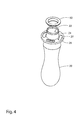
- Figure 4 shows the inner bottle 20 provided with a plug 60 for plugging off of the mouth 25 by interaction with the rim 23 thereof.
- This plug 60 does not form part of the drinks bottle but may be provided as an additional feature to accommodate a possible use scenario involving 'frozen' inner bottle 20 contents.
- the inner bottle 20 is taken and charged with liquid contents.
- the plug 60 is then inserted and the plugged inner bottle 20 is placed in a freezer until frozen.
- the inner bottle 20 is then placed inside the outer bottle making sure that the spacer ring 26 correct locates against the upper neck of inner bottle 14 and the protuberant engagement feature 18 at the inner base of the outer bottle 10 engages with the cavity engagement feature 28 at the outer base of the inner bottle 20.
- the outer bottle 10 is then charged with a second fluid and the lid 30; 130 with sealing ring 50; 150 attached (as in Figures 5 or 7 ) screwed onto the top of the outer bottle to give the use configuration of Figures 1 , 2a and 2b .
- the user may selectively access the liquid contents of the first 12 and second 22 chambers by means of the first 40 and second 45 dispensing outlets respectively. If the frozen contents option has been selected, the frozen core acts to chill the contents of the first chamber 12 of the outer bottle 10. Over time the frozen core will defrost, thereby eventually providing a further liquid drink in the second chamber 22 of the inner bottle 20.
Landscapes
- Engineering & Computer Science (AREA)
- Mechanical Engineering (AREA)
- Ceramic Engineering (AREA)
- Closures For Containers (AREA)
Abstract
There is provided a drinks bottle (1) comprising an outer bottle (10) defining a first chamber (12); receivable wholly or partly within said outer bottle, an inner bottle (20) defining a second chamber (22); and receivable by said outer bottle, a lid (30) defining a first dispensing outlet (40) and a second dispensing outlet (45), wherein in a lidded configuration said first dispensing outlet is in fluid communication only with said first chamber and said second dispensing outlet is in fluid communication only with said second chamber.
Description
- The present invention relates to a drinks bottle providing distinct chambers for separately containing and dispensing plural liquid contents. In embodiments, the drinks bottle may be configured as an infant drinks bottle or as a sports drinks bottle.
- Drinks bottles are well known in the art including those arranged for use in dynamic situations. Specific examples include drinks bottles that are arranged to be suitable for use by infants (e.g. toddlers) as they move around the home or outdoors. Other specific examples include sports drinks bottles that are arranged to be suitable for use by sportsmen and women in the context of training or sporting events. Typically, such drinks bottles comprise a bottle-shaped container defining a chamber, to which is provided a reversibly removable lid having a dispensing outlet (e.g. a spout). Charging of the bottle with liquid contents is achieved by removing the lid and pouring liquid into the chamber. The lid is then replaced and in use, dispensing of liquid to the user is via the dispensing outlet.
- It can be desirable for such drinks bottles to comprise two or more separate chambers, thereby enabling the separate storage of different liquid contents. Thus, in the context of infant drinks bottles a first chamber might contain water whilst a second chamber might contain a fruit juice or squash. The infant may then choose between drinks. Similarly, in the context of sports drinks bottles a first chamber might contain water whilst a second chamber might contain a refreshing (e.g. high energy or isotonic) drink. The sportsman or woman may then choose between different drinks at different points in the sports, training or exercise cycle.
- Applicant has appreciated that from a space efficiency standpoint, it is advantageous that one chamber be arranged to be accommodated inside the other chamber, but that the utility is provided to allow for separate dispensing from each chamber. A further advantage of such a 'chamber-within-a-chamber' arrangement is that the contents of the inner chamber may be frozen such as to act as a 'frozen core' to chill the contents of the outer chamber. During use, the contents of the inner chamber will defrost over time such that these may also later be drunk as a second chilled drink.
- Applicant has further appreciated that such a 'chamber-within-a-chamber' arrangement requires careful configuration in order to effectively allow for separate dispensing from the outer and inner chambers and to ensure for a stable arrangement of features during travel or active usage thereof.
- United States patent publication no.
US2008/000866 describes a dual cavity sports bottle in which separate drinks chambers are arranged to mate together in a spirally intertwined configuration. Such an arrangement is inevitably difficult to manufacture. - United States patent publication no.
US2010/116769 describes a dual chamber bottle, in which separate drinks chambers are arranged in a side-by-side configuration. - It is an object of the present invention to provide a drinks bottle providing different chambers for containing and dispensing separate liquid contents that has enhanced utility for the user.
- According to a first aspect of the present invention there is provided a drinks bottle comprising
an outer bottle defining a first chamber;
receivable wholly or partly within said outer bottle, an inner bottle defining a second chamber; and
receivable by said outer bottle, a lid defining a first dispensing outlet and a second dispensing outlet, wherein in a lidded configuration said first dispensing outlet is in fluid communication only with said first chamber and said second dispensing outlet is in fluid communication only with said second chamber. - There is provided a drinks bottle, which includes outer and inner bottles, which respectively define first and second chambers for separate containment of liquid contents. In preferred embodiments, the drinks bottle comprises only two chambers (i.e. is dual-chambered), but alternatives are also envisaged in which more than two chambers are provided.
- The outer bottle defines a first chamber. The outer bottle may comprise any suitable bottle shaped container. In embodiments, the outer bottle has a base from which upwardly extends side walling, which side walling defines at an end distal from the base a mouth of said outer bottle. A distinct neck may be defined at the distal end such that the mouth is defined at the neck. In embodiments, the side walling comprises a circular or ovular side wall, which may in embodiments taper away from the base and the outer bottle mouth is correspondingly circular or ovular. In embodiments, a defined outer bottle rim may be defined at the mouth of the outer bottle. In embodiments, the outer bottle shape is defined around (e.g. is symmetric around) a central outer bottle axis.
- The inner bottle defines a second chamber. The inner bottle is arranged for receipt wholly or partly within the outer bottle. The inner bottle may also comprise any suitable bottle shaped container. In embodiments, the inner bottle has a base from which upwardly extends side walling, which side walling defines at an end distal from the base a mouth of said inner bottle. A distinct neck may be defined at the distal end such that the mouth is defined at the neck. In embodiments, the side walling comprises a circular or ovular side wall, which in embodiments, tapers away from the base and the inner bottle mouth is correspondingly circular or ovular. In embodiments, a defined inner bottle rim may be defined at the mouth of the inner bottle. In embodiments, the inner bottle shape is defined around (e.g. is symmetric around) a central inner bottle axis. In embodiments, the central inner bottle axis corresponds to (i.e. is co-axial with) the central outer bottle axis.
- In embodiments, the shape profile defined by the outer and inner bottles is generally arranged to correspond. That is to say, in embodiments the shape profile of the inner bottle generally corresponds to or mirrors that of the outer bottle.
- In embodiments, the outer and/or inner bottles are provided with features that allow for particular stable orientation of the inner bottle relative to the outer bottle. In embodiments, the inner and/or outer bottle are provided with one or more spacer features arranged for particular spaced orientation of the inner bottle relative to the outer bottle. In embodiments, the inner and/or outer bottle are provided with one or more engagement features arranged for particular engagement of the inner bottle relative to the outer bottle. Such spacer and/or engagement features are of utility in ensuring a stable arrangement during travel and/or active use of the drinks bottle.
- In embodiments, the spacer and/or engagement features are arranged for retaining (e.g. holding) the inner bottle in coaxial fashion (i.e. with central inner and outer bottle central axes corresponding) with the outer bottle.
- In embodiments, the inner bottle is provided with a spacer ring arranged for interaction with the side wall (e.g. adjacent to the rim thereof) of the outer bottle.
- In embodiments, the inner base of the outer bottle is provided (e.g. at a central point thereof) with a first engagement feature arranged for engagement with a second engagement feature provided at the outer base of the inner bottle. Any suitable mutually engageable features are suitable including tongue / groove; protuberance /cavity and screw-thread engagement type arrangements.
- The lid is arranged for receipt by the outer bottle. In embodiments, the lid is arranged to interact in a reversibly sealable manner (e.g. snap-fit or screw-fit) with the outer bottle to seal off the mouth thereof. In embodiments, the lid is provided with engagement features for reversibly engaging with corresponding engagement features provided to the outer bottle. In embodiments, the exterior of the side walling of the outer bottle is provided with a screw-thread for screw-threaded sealing engagement with a corresponding screw-thread on the lid.
- The lid defines a first dispensing outlet and a second dispensing outlet. Each dispensing outlet may be in the form of a spout or other suitable form, which allows for dispensing to the lips and mouth of a user. Each dispensing outlet (e.g. at a spout thereof) is suitably provided with a valve means arranged such that liquid may only be dispensed through the outlet when the valve is opened. Any suitable valves may be employed including pop-up, push-up, slide and slit valves.
- When the lid is in place (i.e. in a lidded configuration) the first dispensing outlet is in fluid communication only (i.e. exclusively) with the first chamber and the second dispensing outlet is in fluid communication only (i.e. exclusively) with the second chamber. The lid is configured to achieve this functional requirement.
- In embodiments, the lid is configured such as to mate with the (e.g. rim defining the) mouth of the inner bottle to thereby allow for exclusive communication of fluid from the second chamber of the inner bottle to the second dispensing outlet. Thus, one or more mating features may be defined at the lid such as grooves or indents for receipt of the rim defining the mouth of the second chamber of the inner bottle or of a seal element as described below. In embodiments, the lid defines one or more guide features such as a skirt for guiding fluid from the mouth of the second chamber of the inner bottle to the second dispensing outlet.
- In embodiments, the lid is configured such as to mate in sealing fashion with the (e.g. rim defining the) mouth of the inner bottle to thereby allow for exclusive communication of fluid from the second chamber of the inner bottle to the second dispensing outlet. In embodiments, a seal element is provided at the interface between the lid and the (e.g. mouth of the) inner bottle to provide a sealing relationship there between. In embodiments, the seal element is in the form of a washer or sealing ring.
- In embodiments, one or more seal mating features are defined at the seal element for mating relationship with the lid and/or the inner bottle. In embodiments, one or more seal mating features are defined at the seal element such as grooves or indents for receipt of a rim defining the mouth of the second chamber of the inner bottle or for mating relationship with mating features defined at the lid. In embodiments, the seal element (e.g. in the form of a sealing ring) has a seal mating feature comprising a circular (e.g. circumferential) skirt.
- In embodiments, one or more lid mating features are defined at the lid for mating relationship with the seal element. In embodiments, the lid has a lid mating feature comprising a circular groove (e.g. arranged for mating with a circular (e.g. circumferential) skirt of the seal element).
- The lid may be provided with one or more vent holes. In embodiments, a first vent hole is provided to allow for venting of the outer bottle chamber. In embodiments, a second vent hole is provided to allow for venting of the inner bottle chamber. In embodiments, any vent hole is provided with a valve such as a one-way valve arranged to allow for venting from the relevant chamber in response to applied pressure. In embodiments, the one-way valve is responsive to sucking action of the user (e.g. a slit valve or duck bill valve) at the relevant dispensing outlet.
- In embodiments, where a second vent hole is provided to allow for venting of the inner bottle chamber and a seal element is provided at the interface between the lid and the mouth of the inner bottle to provide a sealing relationship there between the seal element may be adapted to allow for sealing of the second vent hole. In embodiments, the seal element is further provided with a valve such as a one-way valve arranged to allow for venting of the inner bottle chamber via the second vent hole in response to applied pressure. In embodiments, the one-way valve is responsive to sucking action of the user (e.g. a slit valve or duck bill valve) at the second dispensing outlet.
- In embodiments, the outer bottle is provided with one or more handles extending from a lower portion of the outer bottle to an upper portion thereof. In embodiments, the one or more handles extend from the base of the outer bottle up and around to the mouth thereof.
- The drinks bottle herein may be formed of any suitable materials including plastic materials formed by a suitable moulding operation such as blow moulding.
- It will be appreciated that any of the elements of the drinks bottle herein may be manufactured and supplied separately and /or supplied as a pre-assembly or a kit of parts. The present invention encompasses all of these separate component parts and any assemblies thereof.
- The invention will now be described further with reference to the accompanying drawings, in which:-
-
Figure 1 shows a perspective view of a drinks bottle herein; -
Figure 2a shows a side view of the drinks bottle ofFigure 1 ; -
Figure 2b shows a sectional view of the drinks bottle ofFigure 1 wherein the section is taken along line A-A ofFigure 2a ; -
Figure 3 shows an exploded view of the drinks bottle ofFigure 1 ; -
Figure 4 shows the inner bottle part of the drinks bottle ofFigure 1 now provided with a plug for use in freezer storage of the inner bottle; -
Figure 5 shows an underside view of an assembly of the lid and sealing ring of the drinks bottle ofFigure 1 ; -
Figure 6 shows an underside view of the lid of the drinks bottle ofFigure 1 ; -
Figure 7 shows an underside view of an assembly of an alternative lid with vent hole and sealing ring with slit valve for vent hole for use with a variant of the drinks bottle ofFigure 1 ; and -
Figure 8 shows an underside view of an alternative lid with vent hole for use with a variant of the drinks bottle ofFigure 1 . - Referring now to the drawings,
Figures 1 to 3 show different views of adrinks bottle 1 herein, comprising anouter bottle 10 defining afirst chamber 12 and receivable within saidouter bottle 10, aninner bottle 20 defining asecond chamber 22. Thedrinks bottle 1 is provided with alid 30 that defines inner screw-thread 32 arranged for screw-threaded engagement with outer screw-thread 13 (seeFigure 2b ) provided about theupper neck 14 of theouter bottle 10, which also hasopen mouth 16 surrounded byrim 15. The inner bottle also definesneck 24 andopen mouth 25 defined byrim 23. - It may be noted that the shape of the
outer bottle 10 is defined around a central outer bottle axis, which corresponds essentially to line A-A ofFigure 2a . Correspondingly, the shape of theinner bottle 20 is also defined around that same axis. That is to say, the central inner bottle axis is co-axial with the central outer bottle axis. It will be appreciated that each of the outer and inner bottles defines a generally circular cross-section in the plane that lies perpendicular to the bottle axes (line A-A). It will also be noted that at least the lower shape profile defined by theouter bottle 10 andinner bottle 20 generally corresponds at least in the lower regions thereof. - The
outer bottle 10 andinner bottle 20 are both provided with features that allow for co-axial orientation of theinner bottle 20 relative to theouter bottle 10. Thus, theinner bottle 20 is provided with aspacer ring 26 having flow holes 27 therein arranged for spacing interaction with the inner wall of theupper neck 14 of the outer bottle 10 (seeFigure 2b ). As shown atFigure 2b , the inner base of theouter bottle 10 is provided at a central point thereof with aprotuberant engagement feature 18 arranged for engagement with acavity engagement feature 28 provided at the outer base of theinner bottle 20. Overall, the action of both thespacer ring 26 / upper neck ofinner bottle 14 andengagement feature inner bottle 20 in place along the central axis (line A-A) of theouter bottle 10. - The
lid 30 is arranged for sealing receipt by theouter bottle 10. Thelid 30 defines afirst dispensing outlet 40 and asecond dispensing outlet 45. Each dispensingoutlet outlet cap valve outlet 40; 45 arranged such that liquid may only be dispensed through the outlet when the valve is opened in response to pushing up of therelevant cap valves US2008/000866 . - In a lidded configuration (see
Figures 1 ,2a and 2b ) thefirst dispensing outlet 40 is in fluid communication exclusively with thefirst chamber 12 of theouter bottle 10 and thesecond dispensing outlet 45 is in fluid communication exclusively with thesecond chamber 22 of theinner bottle 20. Thelid 30 is suitably configured to achieve this functional requirement of thedrinks bottle 1. - The
lid 30 engages in screw-thread fashion with theouter bottle 10. As described below, thesecond chamber 22 of the inner bottle mates with thelid 30 such that fluid may exit thatsecond chamber 22 only through thesecond dispensing outlet 45. In effect, the fluid contents of the inner 20 and outer 10 bottles are isolated from each other. Fluid flow from thefirst chamber 12 of theouter bottle 10 is thus, exclusively through thefirst dispensing outlet 40 under the control of push-upvalve - In more detail, the
lid 30 is configured such as to mate via sealingring 50 with therim 23 that defines themouth 25 of theinner bottle 20 to thereby allow for exclusive communication of fluid fromsecond chamber 22 of theinner bottle 20 to thesecond dispensing outlet 45.Figure 5 shows an assembly of thelid 30 and sealingring 50 andFigure 6 shows details of the underside of thelid 30. Thus, in more detail, upper circumferential skirt 52 (seeFigures 2b and3 ) of the sealingring 50 is arranged for receipt bycircular groove 34 of the inner part oflid 30 to form the assembly as shown atFigure 6 (see alsoFigure 2b ). In the assembled drinks bottle 1 (seeFigure 2b ) rim 23 of theinner bottle 20 seats in sealing fashion up against sealingring 50, which is itself received in mating fashion bylid 30 by virtue of the interaction betweenskirt 52 andgroove 34. Fluid flow from thesecond chamber 22 of theinner bottle 20 is thus, exclusively through thesecond dispensing outlet 45 under the control of push-upvalve -
Figures 7 and8 show a second embodiment of alid 130 and sealingring 150 that may be used with thedrinks bottle 1 ofFigures 1 to 3 . This variant of thelid 130 and sealingring 150 differs from the lid ofFigures 5 and6 only in that it is configured to allow for venting of theinner bottle 20. - In more detail,
lid 130 withsecond dispensing outlet 145 is thus provided with avent hole 138, which is configured in use, allow for venting of thechamber 22 of theinner bottle 20. The sealingring 150 is accordingly modified to include a 'half moon'side sealing element 154, which in the lid / sealing ring assembly locates above the vent hole 138 (seeFigure 7 ). The sealingring 150 includes upper circumferential skirt (not visible, but identical to skirt 52) and 'half-moon'side sealing element 154 is also provided with a 'half-moon' shaped skirt (not visible) arranged for receipt by half-moon groove 135 onlid 130. Thus, the skirts of sealingring 150 and itsside sealing element 154 interact withcorresponding grooves groove 34 /skirt 52 interaction oflid 30, thereby securing the sealingring 150 andside element 154 to thelid 130. Theside sealing element 154 is provided with aslit valve 156 that operates as a one-way valve forvent hole 138 such as to allow for venting from thesecond chamber 22 of theinner bottle 20 in response to applied pressure. In use, this one-way slit valve 156 is arranged to be responsive to sucking action of the user at thesecond dispensing outlet 145, thereby enhancing ease of liquid dispensing from thesecond dispensing outlet 145. -
Figure 4 shows theinner bottle 20 provided with aplug 60 for plugging off of themouth 25 by interaction with therim 23 thereof. Thisplug 60 does not form part of the drinks bottle but may be provided as an additional feature to accommodate a possible use scenario involving 'frozen'inner bottle 20 contents. - Thus, in one possible use scenario the
inner bottle 20 is taken and charged with liquid contents. In an optional step, theplug 60 is then inserted and the pluggedinner bottle 20 is placed in a freezer until frozen. Theinner bottle 20 is then placed inside the outer bottle making sure that thespacer ring 26 correct locates against the upper neck ofinner bottle 14 and theprotuberant engagement feature 18 at the inner base of theouter bottle 10 engages with thecavity engagement feature 28 at the outer base of theinner bottle 20. Theouter bottle 10 is then charged with a second fluid and thelid 30; 130 with sealingring 50; 150 attached (as inFigures 5 or7 ) screwed onto the top of the outer bottle to give the use configuration ofFigures 1 ,2a and 2b . - The user may selectively access the liquid contents of the first 12 and second 22 chambers by means of the first 40 and second 45 dispensing outlets respectively. If the frozen contents option has been selected, the frozen core acts to chill the contents of the
first chamber 12 of theouter bottle 10. Over time the frozen core will defrost, thereby eventually providing a further liquid drink in thesecond chamber 22 of theinner bottle 20.
Claims (15)
- A drinks bottle comprising
an outer bottle defining a first chamber;
receivable wholly or partly within said outer bottle, an inner bottle defining a second chamber; and
receivable by said outer bottle, a lid defining a first dispensing outlet and a second dispensing outlet, wherein in a lidded configuration said first dispensing outlet is in fluid communication only with said first chamber and said second dispensing outlet is in fluid communication only with said second chamber. - A drinks bottle according to claim 1, wherein the outer and/or the inner bottle are provided with one or more spacer features arranged for spacing of the inner bottle relative to the outer bottle.
- A drinks bottle according to claim 2, wherein said one or more spacer features are arranged for spacing the inner bottle in coaxial fashion with the outer bottle.
- A drinks bottle according to either of claims 2 or 3, wherein the inner bottle is provided with a spacer ring arranged for spacing interaction with a side wall of the outer bottle.
- A drinks bottle according to any of claims 1 to 4, wherein the outer and/or inner bottle are provided with one or more engagement features arranged for engaging of the inner bottle relative to the outer bottle, preferably for engaging the inner bottle in coaxial fashion with the outer bottle.
- A drinks bottle according to claim 5, wherein an inner base of the outer bottle is provided with a first engagement feature arranged for engagement with a second engagement feature provided at the outer base of the inner bottle, preferably wherein said first engagement feature is a cavity locating centrally at said inner base of the outer bottle and said second engagement feature is a protuberance locating centrally at said outer base of the inner bottle.
- A drinks bottle according to any of claims 1 to 6, wherein the lid defines one or more mating features for mating relationship with the inner bottle.
- A drinks bottle according to any of claims 1 to 7, wherein the lid defines one or more guide features for guiding fluid from the second chamber to the second dispensing outlet.
- A drinks bottle according to any of claims 1 to 8, wherein a seal element is provided at the interface between the lid and the inner bottle to provide a sealing relationship there between, preferably wherein said seal element is in the form of a washer or sealing ring.
- A drinks bottle according to claim 9, wherein one or more seal mating features are defined at the seal element for mating relationship with the lid and/or the inner bottle.
- A drinks bottle according to claim 10, wherein the seal element has a seal mating feature comprising a circular skirt.
- A drinks bottle according to any of claims 9 to 11, wherein one or more lid mating features are defined at the lid for mating relationship with the seal element.
- A drinks bottle according to claim 12, wherein the lid has a lid mating feature comprising a circular groove.
- A drinks bottle according to any of claims 1 to 13, wherein the lid is provided with a first vent hole to allow for venting of the outer bottle chamber and/or a second vent hole to allow for venting of the inner bottle chamber, preferably wherein either said first or said second vent hole is provided with a one-way valve arranged only to allow for venting from the relevant chamber in response to applied pressure.
- A drinks bottle according to claim 14, wherein the second vent hole is present and a seal element is provided at the interface between the lid and the inner bottle to provide a sealing relationship there between and wherein said seal element is adapted to allow for reversible sealing of the second vent hole, preferably wherein the seal element is further provided with a one-way valve arranged only to allow for venting of the inner bottle chamber via the second vent hole in response to applied pressure.
Applications Claiming Priority (1)
| Application Number | Priority Date | Filing Date | Title |
|---|---|---|---|
| GBGB1206979.5A GB201206979D0 (en) | 2012-04-20 | 2012-04-20 | Drinks bottle |
Publications (1)
| Publication Number | Publication Date |
|---|---|
| EP2653405A1 true EP2653405A1 (en) | 2013-10-23 |
Family
ID=46261628
Family Applications (1)
| Application Number | Title | Priority Date | Filing Date |
|---|---|---|---|
| EP13162079.1A Withdrawn EP2653405A1 (en) | 2012-04-20 | 2013-04-03 | Drinks bottle |
Country Status (4)
| Country | Link |
|---|---|
| US (1) | US20130277326A1 (en) |
| EP (1) | EP2653405A1 (en) |
| CN (1) | CN203246653U (en) |
| GB (2) | GB201206979D0 (en) |
Cited By (4)
| Publication number | Priority date | Publication date | Assignee | Title |
|---|---|---|---|---|
| WO2018234276A1 (en) | 2017-06-21 | 2018-12-27 | Nestec S.A. | LIQUID DISPENSING APPARATUS |
| WO2018234275A1 (en) | 2017-06-21 | 2018-12-27 | Nestec S.A. | Liquid dispensing apparatus |
| WO2019101973A1 (en) | 2017-11-24 | 2019-05-31 | Nestec S.A. | Attachment for a beverage container |
| US12378036B1 (en) | 2023-01-31 | 2025-08-05 | Michael Desravines | Combination drink container and sanitizer dispenser |
Families Citing this family (7)
| Publication number | Priority date | Publication date | Assignee | Title |
|---|---|---|---|---|
| US9452440B2 (en) * | 2014-05-21 | 2016-09-27 | Triumph Pharmaceuticals Inc. | Multi-chambered bottle with metering stage, pour spout and cap |
| USD764920S1 (en) * | 2014-11-13 | 2016-08-30 | Cornerstone Cm, Inc. | Bottle |
| US20160288944A1 (en) * | 2015-03-31 | 2016-10-06 | Brandon Edward Matz | Liquid filled container and method of manufacture |
| CN105836305A (en) * | 2016-06-08 | 2016-08-10 | 杜海峰 | Self-mixing blend oil packaging container |
| USD803071S1 (en) | 2016-06-16 | 2017-11-21 | Daniel Telu-Zoltner | Bottle having three compartments |
| CN110722771B (en) * | 2019-10-23 | 2021-08-24 | 广州小大包装有限公司 | Cosmetic container manufacturing process |
| CN111891525A (en) * | 2020-09-08 | 2020-11-06 | 河南今日开口贸易有限公司 | a container bottle |
Citations (5)
| Publication number | Priority date | Publication date | Assignee | Title |
|---|---|---|---|---|
| US3851800A (en) * | 1973-08-20 | 1974-12-03 | Cambridge Res & Dev Group | Plural chambered, gravity oriented dispenser |
| DE3514134A1 (en) * | 1985-04-19 | 1986-10-23 | Wella Ag, 6100 Darmstadt | Multiple-chamber container |
| US20060102581A1 (en) * | 2004-11-15 | 2006-05-18 | Yates William M Iii | Multiple chamber bottle and method of filling and assembling same |
| US20080000866A1 (en) | 2004-09-15 | 2008-01-03 | Yates William M Iii | Dual cavity sports bottle with source selecting closure |
| US20100116769A1 (en) | 2008-11-12 | 2010-05-13 | Theodosios Kountotsis | Dual chamber bottle and method of manufacturing the same |
Family Cites Families (47)
| Publication number | Priority date | Publication date | Assignee | Title |
|---|---|---|---|---|
| US132020A (en) * | 1872-10-08 | Improvement in bottles | ||
| US551797A (en) * | 1895-12-24 | Vessel for liquids | ||
| US284127A (en) * | 1883-08-28 | Jacob geuenebaum | ||
| US200065A (en) * | 1878-02-05 | Improvement in flasks for cooling liquids | ||
| US1418814A (en) * | 1920-09-25 | 1922-06-06 | Daniel E Lutz | Bottle |
| US1511817A (en) * | 1923-09-08 | 1924-10-14 | George F Montague | Receptacle |
| US1699532A (en) * | 1924-07-11 | 1929-01-22 | Gilmont Products Gorporation | Multiple collapsible tube |
| US1913460A (en) * | 1933-01-26 | 1933-06-13 | Edward E Smetana | Container |
| US2160165A (en) * | 1936-10-14 | 1939-05-30 | John V Patterson | Nondiluting cooling device |
| US2142644A (en) * | 1938-04-04 | 1939-01-03 | Albert M Moore | Valve controlled bottle closure |
| US2321998A (en) * | 1942-04-04 | 1943-06-15 | Eastman Kodak Co | Two-compartment container |
| US2385648A (en) * | 1944-06-16 | 1945-09-25 | Prager Martin | Double container |
| US3038623A (en) * | 1961-02-01 | 1962-06-12 | Crunden Martin Mfg Co | Spaced wall container |
| US3120570A (en) * | 1961-04-20 | 1964-02-04 | Southern California Plastic Co | Process for forming an insulated container |
| US3200995A (en) * | 1962-08-30 | 1965-08-17 | Colgate Palmolive Co | Multicompartment dispensing package |
| LU46381A1 (en) * | 1964-07-07 | 1972-01-01 | ||
| US3722538A (en) * | 1971-03-10 | 1973-03-27 | Itt | Blind cavity holding sump |
| US4277000A (en) * | 1979-05-17 | 1981-07-07 | Celanese Corporation | Multi-compartment containers |
| US4362250A (en) * | 1981-03-26 | 1982-12-07 | National Distillers & Chemical Corp. | Container for storing reactive or volatile material |
| USD323108S (en) * | 1989-02-21 | 1992-01-14 | Green Richard D | Dual compartment bottle |
| US5392947A (en) * | 1993-10-29 | 1995-02-28 | Chesebrough-Pond's Usa Co., Division Of Conopco, Inc. | Dental mouthwash product |
| USD364344S (en) * | 1994-06-29 | 1995-11-21 | Shaw Howard G | Split lid container |
| USD399098S (en) * | 1997-03-31 | 1998-10-06 | Heng-Te Yang | Container |
| US5904267A (en) * | 1997-06-17 | 1999-05-18 | Thompson; Patrick | No-ice cooler |
| US6161777A (en) * | 1997-08-08 | 2000-12-19 | C. Michael Carter | Portable spraying and drinking apparatus |
| US5968618A (en) * | 1998-04-13 | 1999-10-19 | Miller; Blair J. | Thermal coffee carafe |
| US6116458A (en) * | 1999-02-25 | 2000-09-12 | Dark; Richard C. G. | Sport drinking cup with valved straw cap |
| US6010034A (en) * | 1999-03-08 | 2000-01-04 | Premium Designs, Llc | Combination drink and spray sports bottle |
| USD431158S (en) * | 1999-03-19 | 2000-09-26 | Paul Schwab | Multiple use water dispenser |
| USD451029S1 (en) * | 2000-04-05 | 2001-11-27 | Agilent Technologies, Inc. | Container for liquids |
| US6332557B1 (en) * | 2001-01-12 | 2001-12-25 | Megatrade International, Inc. | Bottle with dual interlocking cups and modular base assembly |
| US6629618B1 (en) * | 2001-02-06 | 2003-10-07 | Ken Michael Volan | Thermally insulated glass bottle |
| US6913777B2 (en) * | 2001-02-12 | 2005-07-05 | General Mills, Inc. | Portable, side-by-side compartment container and method for separately storing and dispensing two consumable products, especially cereal and milk |
| US6766915B2 (en) * | 2002-12-19 | 2004-07-27 | Ming-Feng Wu | Drink container for small children |
| US7270244B1 (en) * | 2004-01-22 | 2007-09-18 | Pacific Cornetta, Inc. | Polycarbonate double walled liquid holding vessel |
| US20050284835A1 (en) * | 2004-06-23 | 2005-12-29 | Mckendry Bruce | Insulated food containers |
| US7337923B2 (en) * | 2004-07-08 | 2008-03-04 | Decko Products, Inc. | Variable tip nozzle and cap assembly for dispensing pouch |
| US7143958B1 (en) * | 2005-03-25 | 2006-12-05 | Whirley Industries, Inc. | Misting bottle system |
| US20070090077A1 (en) * | 2005-10-03 | 2007-04-26 | Graber Loren R | Container arrangement |
| TWM326384U (en) * | 2007-08-07 | 2008-02-01 | Co Union Industry Co Ltd | Cold preserving pot |
| US20090134110A1 (en) * | 2007-11-28 | 2009-05-28 | David Carl Jones | Bottle and valve for holding and dispensing multiple substances |
| US20090294397A1 (en) * | 2008-05-27 | 2009-12-03 | Wu Kuo Cheng | Container for contain different beverages |
| US8240497B2 (en) * | 2008-11-12 | 2012-08-14 | Theodosios Kountotsis | Dual chamber bottle and method of manufacturing the same |
| US8499960B2 (en) * | 2010-12-08 | 2013-08-06 | Carrie Paterson | Integral container having concentric compartments for multiple distinct fluids |
| USD659473S1 (en) * | 2011-04-06 | 2012-05-15 | Mohssen Ghiassi | Water bottle with hygienic filtration |
| USD684805S1 (en) * | 2011-11-11 | 2013-06-25 | Designers Company Aps | Carafe |
| USD683188S1 (en) * | 2012-06-23 | 2013-05-28 | Jonathan Morris Gold | Drinking bottle |
-
2012
- 2012-04-20 GB GBGB1206979.5A patent/GB201206979D0/en not_active Ceased
- 2012-09-07 US US13/606,067 patent/US20130277326A1/en not_active Abandoned
-
2013
- 2013-04-02 GB GB1305886.2A patent/GB2501389B/en not_active Expired - Fee Related
- 2013-04-03 EP EP13162079.1A patent/EP2653405A1/en not_active Withdrawn
- 2013-04-09 CN CN201320175003.XU patent/CN203246653U/en not_active Expired - Fee Related
Patent Citations (5)
| Publication number | Priority date | Publication date | Assignee | Title |
|---|---|---|---|---|
| US3851800A (en) * | 1973-08-20 | 1974-12-03 | Cambridge Res & Dev Group | Plural chambered, gravity oriented dispenser |
| DE3514134A1 (en) * | 1985-04-19 | 1986-10-23 | Wella Ag, 6100 Darmstadt | Multiple-chamber container |
| US20080000866A1 (en) | 2004-09-15 | 2008-01-03 | Yates William M Iii | Dual cavity sports bottle with source selecting closure |
| US20060102581A1 (en) * | 2004-11-15 | 2006-05-18 | Yates William M Iii | Multiple chamber bottle and method of filling and assembling same |
| US20100116769A1 (en) | 2008-11-12 | 2010-05-13 | Theodosios Kountotsis | Dual chamber bottle and method of manufacturing the same |
Cited By (5)
| Publication number | Priority date | Publication date | Assignee | Title |
|---|---|---|---|---|
| WO2018234276A1 (en) | 2017-06-21 | 2018-12-27 | Nestec S.A. | LIQUID DISPENSING APPARATUS |
| WO2018234275A1 (en) | 2017-06-21 | 2018-12-27 | Nestec S.A. | Liquid dispensing apparatus |
| WO2019101973A1 (en) | 2017-11-24 | 2019-05-31 | Nestec S.A. | Attachment for a beverage container |
| EP4089032A1 (en) | 2017-11-24 | 2022-11-16 | Société des Produits Nestlé S.A. | Attachment for a beverage container |
| US12378036B1 (en) | 2023-01-31 | 2025-08-05 | Michael Desravines | Combination drink container and sanitizer dispenser |
Also Published As
| Publication number | Publication date |
|---|---|
| US20130277326A1 (en) | 2013-10-24 |
| GB201305886D0 (en) | 2013-05-15 |
| GB2501389A (en) | 2013-10-23 |
| CN203246653U (en) | 2013-10-23 |
| GB201206979D0 (en) | 2012-06-06 |
| GB2501389B (en) | 2015-01-14 |
Similar Documents
| Publication | Publication Date | Title |
|---|---|---|
| US20130277326A1 (en) | Drinks bottle | |
| RU2713343C2 (en) | Liquid dispensing container with multi-position valve and drinking straw | |
| US8616390B2 (en) | Triple chamber bottle and method of manufacturing the same | |
| US20180029752A1 (en) | Two-in-one drinking vessel | |
| US20140299614A1 (en) | Splash and spill resistant lid | |
| US20150251818A1 (en) | Lid with rotatable closure tab | |
| US20130233869A1 (en) | Lid with cap for beverage receptacle | |
| US20100116769A1 (en) | Dual chamber bottle and method of manufacturing the same | |
| JP2012517386A (en) | Beverage container closure | |
| US20150353259A1 (en) | Dual Chamber SportzBottle with 2-N-1 and 2-To-1 Flip-up Spout Lids | |
| US8123087B2 (en) | Container with extendable spout | |
| US7165697B1 (en) | Concentric two-compartment drinking vessel | |
| US20210030176A1 (en) | Dual Chambered Canteen with Interchangeable Lids | |
| KR101348415B1 (en) | 2-pack beverage container | |
| KR101553337B1 (en) | Receipt case of a tea bag for mineral water case | |
| KR101450181B1 (en) | Cup lid for mounting of the capsule | |
| US20040262252A1 (en) | Mug fixed to the top or to the bottom of a beverage bottle beverage bottle designed for receiving same, and related combination | |
| US20220234811A1 (en) | Container system including lid with improved neck insulation | |
| US20230009089A1 (en) | Shot straws and methods for making and using the same | |
| KR102165020B1 (en) | Straw for drink container | |
| JP2024502681A (en) | beverage container | |
| KR101376289B1 (en) | Kit for making mixture berverage | |
| KR101349435B1 (en) | Multi-cup | |
| US20130092699A1 (en) | Beverage can sealer and holder | |
| CA2916496A1 (en) | Container lid construction and associated methods |
Legal Events
| Date | Code | Title | Description |
|---|---|---|---|
| PUAI | Public reference made under article 153(3) epc to a published international application that has entered the european phase |
Free format text: ORIGINAL CODE: 0009012 |
|
| AK | Designated contracting states |
Kind code of ref document: A1 Designated state(s): AL AT BE BG CH CY CZ DE DK EE ES FI FR GB GR HR HU IE IS IT LI LT LU LV MC MK MT NL NO PL PT RO RS SE SI SK SM TR |
|
| AX | Request for extension of the european patent |
Extension state: BA ME |
|
| STAA | Information on the status of an ep patent application or granted ep patent |
Free format text: STATUS: THE APPLICATION IS DEEMED TO BE WITHDRAWN |
|
| 18D | Application deemed to be withdrawn |
Effective date: 20140424 |