EP2653023A1 - Behälter landwirtschaftlicher Verteilmaschinen - Google Patents
Behälter landwirtschaftlicher Verteilmaschinen Download PDFInfo
- Publication number
- EP2653023A1 EP2653023A1 EP13401036.2A EP13401036A EP2653023A1 EP 2653023 A1 EP2653023 A1 EP 2653023A1 EP 13401036 A EP13401036 A EP 13401036A EP 2653023 A1 EP2653023 A1 EP 2653023A1
- Authority
- EP
- European Patent Office
- Prior art keywords
- protective device
- container
- parts
- intermediate elements
- locking
- Prior art date
- Legal status (The legal status is an assumption and is not a legal conclusion. Google has not performed a legal analysis and makes no representation as to the accuracy of the status listed.)
- Granted
Links
Images


Classifications
-
- A—HUMAN NECESSITIES
- A01—AGRICULTURE; FORESTRY; ANIMAL HUSBANDRY; HUNTING; TRAPPING; FISHING
- A01C—PLANTING; SOWING; FERTILISING
- A01C15/00—Fertiliser distributors
- A01C15/005—Undercarriages, tanks, hoppers, stirrers specially adapted for seeders or fertiliser distributors
- A01C15/006—Hoppers
Definitions
- the invention relates to a container agricultural distribution machines according to the preamble of claim 1.
- Such a container agricultural distribution machines is in the DE 103 48 067 B4 described.
- the protective device arranged in the storage container is designed as a sieve-like element and arranged in the upper region within a container of a distributor.
- the protective device is locked by means of at least one locking element.
- the locking element can be pivoted only by a handle to be inserted in a recess of the connecting element, so that then only in a deliberate manner, the protection device can be opened.
- the protection device In order to lock the protection device via the locking element, the protection device must be pressed under the locking element. If this is forgotten when closing the guard, it can not easily be detected remotely whether the guard is actually locked.
- the invention is based on the object to indicate to the operator of the distributor in a simple manner that the protective device is obviously not properly locked.
- This object is achieved in that between the protective device and the container parts on the side of the protective device on which it is articulated with joints on the container parts, resilient and the protective device in the opening direction moving intermediate elements are arranged.
- the protective device if it is not locked correctly, held by the resilient intermediate elements as far from the actual protective position that the operator is immediately recognizable that the guard is not in the protective position and still needs to be locked in the protective position.
- monitoring electronics create a robust and secure display option for displaying the locking of the protection device in the locked position.
- a simple embodiment of the resilient intermediate elements can be achieved in that the intermediate elements are designed as rubber buffers or spring elements.
- the protective device can be pressed by the intermediate elements by at least 10 ° from the closed locking position in the opening direction.
- the protective device via the intermediate elements, after the unlocking of the locking element at least until outside the Locking range of the locking element can be pressed.
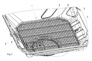
- the sieve element 3 is pivotally mounted on the one hand by means of hinges 4, not shown, to the container part 5 of the container 2 which is designed as a container wall 5.
- the sieve element 3 is spaced from the joints 4 by means of support elements 6, which are formed on the vessel wall 5 as a container parts are attached to container parts 5, which are formed by the container wall on.
- a locking element 7 for locking the screen element in the protective position according to the Fig. 1 and 2 assigned. Due to the fact that the sieve element 3, which forms the protective device, does not bear directly on the wall 5 of the container 2 but rests on support elements 6 fastened to the container wall 5, a gentle support of the sieve element 3 on the container wall 4 is achieved, so that the Sieve element 3 or attached to the screen element 3 abutment is not directly applied to the container wall 5 and thus can not scrape off paint.
- the protective device 3 is on the rubber buffer 9 by at least 10 ° from the closed locking position according to the Fig. 1 and 2 in the opening direction 10 can be pressed, so it has a distance from the locking element 7.
- the protective device 3 is pressed by pushing up on the intermediate elements 9 after unlocking the locking element 7 at least to outside the locking area of the locking element 7.
- the raised position of the wire 3 according to Fig. 3 operator can be recognized immediately.
- This raised position of the wire 3 signals to the operator of the machine that the wire 3 is not in the locked protective position and has not yet been locked.
- the operator can now lock the screen in protection position in accordance with the Fig. 1 and 2 make.
- the intermediate elements may also be designed as spring elements.
Landscapes
- Life Sciences & Earth Sciences (AREA)
- Soil Sciences (AREA)
- Environmental Sciences (AREA)
- Soil Working Implements (AREA)
- Lock And Its Accessories (AREA)
- Packaging Of Machine Parts And Wound Products (AREA)
Abstract
Description
- Die Erfindung betrifft einen Behälter landwirtschaftlicher Verteilmaschinen gemäß des Oberbegriffes des Patentanspruches 1.
- Ein derartiger Behälter landwirtschaftlicher Verteilmaschinen ist in der
DE 103 48 067 B4 beschrieben. - Die im Vorratsbehälter angeordnete Schutzeinrichtung ist als siebartiges Element ausgebildet und im oberen Bereich innerhalb eines Behälters einer Verteilmaschine angeordnet. Um einen unbefugten Zugang zu sich in dem Behälter befindlichen motorisch bewegbaren Teilen zu verhindern, ist die Schutzeinrichtung mittels zumindest eines Verriegelungselementes verriegelt. Das Verriegelungselement kann nur durch ein in einer Aussparung des Verbindungselementes einzusteckende Handhabe verschwenkt werden, so dass dann nur in bewusster Weise die Schutzvorrichtung aufgeklappt werden kann.
- Um die Schutzvorrichtung über das Verriegelungselement zu verriegeln, muss die Schutzvorrichtung unter das Verriegelungselement gedrückt werden. Falls dies vergessen wird beim Schließen der Schutzeinrichtung, kann aus der Ferne nicht leicht erkannt werden, ob die Schutzvorrichtung tatsächlich verriegelt ist.
- Der Erfindung liegt die Aufgabe zu Grunde, dem Bediener der Verteilmaschine in einfacher Weise anzuzeigen, dass die Schutzeinrichtung offensichtlich nicht richtig verriegelt ist.
- Diese Aufgabe wird erfindungsgemäß dadurch gelöst, dass zwischen der Schutzeinrichtung und den Behälterteilen auf der Seite der Schutzeinrichtung, auf welcher sie mit Gelenken an den Behälterteilen angelenkt ist, federnde und die Schutzeinrichtung in Öffnungsrichtung bewegende Zwischenelemente angeordnet sind.
- Infolge dieser Maßnahmen wird die Schutzeinrichtung, wenn sie nicht korrekt verriegelt ist, durch die federnden Zwischenelemente soweit von der eigentlichen Schutzposition gehalten, dass für den Bediener sofort erkennbar ist, dass die Schutzeinrichtung sich nicht der Schutzposition befindet und noch in Schutzposition verriegelt werden muss. So lässt sich ohne weiteren technischen Aufwand, wie der Einsatz von Überwachungssensoren, Überwachungselektronik eine robuste und sicher arbeitende Anzeigemöglichkeit zur Anzeige der Verriegelung der Schutzeinrichtung in Verriegelungsposition schaffen.
- Eine einfache Ausgestaltung der federnde Zwischenelemente lässt sich dadurch erreichen, dass die Zwischenelemente als Gummipuffer oder Federelemente ausgebildet sind.
- Um in ausreichender Weise sichtbar zu machen, ob die Schutzeinrichtung sich in der Verriegelungsposition befindet, ist vorgesehen, dass die Schutzeinrichtung über die Zwischenelemente um zumindest 10° aus der geschlossenen Verriegelungsstellung in Öffnungsrichtung drückbar ist.
- Um ausreichend deutlich sichtbar zu machen, dass die Schutzeinrichtungen sich nicht in Verriegelungsposition befindet, ist vorgesehen, dass die Schutzeinrichtung über die Zwischenelemente nach der Entriegelung des Verriegelungselementes zumindest bis außerhalb des Verriegelungsbereiches des Verriegelungselementes drückbar ist.
- Weitere Einzelheiten der Erfindung sind der Beispielsbeschreibung und den Zeichnungen zu entnehmen. Hierbei zeigen
- Fig. 1
- die in einem trichterförmigen Bereich eines Vorratsbehälters angeordnete Schutzvorrichtung mit Verriegelungselement in Teilansicht und den perspektivischer Darstellung,
- Fig. 2
- die im Vorratsbehälter angeordnete Schutzvorrichtung in der Position gemäß
Fig. 1 in Verriegelungsstellung und im Schnitt II - II, - Fig. 3
- die im Vorratsbehälter angeordnete Schutzvorrichtung nach dem Lösen der Verriegelung und in durch die federnden Zwischenelemente hochgedrückten Position in der Darstellungsweise nach
Fig. 2 und - Fig. 4
- die Anordnung der federnden Zwischenelemente entsprechend
Fig. 3 in vergrößertem Maßstab. - In dem unteren Bereich 1, der trichterförmig ausgebildet ist, des Vorratsbehälters 2 einer landwirtschaftlichen Verteilmaschine ist die als Siebelement 3 ausgebildete Schutzvorrichtung angeordnet. Das Siebelement 3 ist auf der einen Seite mittels nicht dargestellten Gelenken 4 an den als Behälterwand 5 ausgebildeten Behälterteilen des Behälters 2 schwenkbar befestigt. Andererseits liegt das Siebelement 3 beabstandet zu den Gelenken 4 mittels Auflageelementen 6, die an den als Behälterwand 5 ausgebildeten Behälterteilen befestigt sind, an Behälterteilen 5, die von der Behälterwand gebildet werden, an.
- Auf der den Gelenken 4 gegenüberliegenden Seite der Schutzeinrichtung 3 ist ein Verriegelungselement 7 zur Verriegelung des Siebelementes in der Schutzposition gemäß den
Fig. 1 und2 zugeordnet. Dadurch, dass das Siebelement 3, welches die Schutzeinrichtung bildet, nicht unmittelbar an der Wand 5 des Behälters 2 anliegt, sondern auf an der Behälterwand 5 befestigten Auflageelementen 6 aufliegt, wird eine schonende Auflage des Siebelementes 3 an der Behälterwand 4 erreicht, so dass das Siebelement 3 bzw. an dem Siebelement 3 befestigte Gegenlager nicht unmittelbar an der Behälterwand 5 anliegt und somit keine Farbe abschaben kann. - Zwischen der Schutzeinrichtung 3 und den Behälterteilen 5 auf der Seite 8 der Schutzeinrichtung 3, auf welcher sie mit Gelenken 4 an den Behälterteilen 5 angelenkt ist, sind als Gummipuffer 9 ausgebildete federnde und die Schutzeinrichtung 3 in Öffnungsrichtung, wie durch den Pfeil 10 angedeutet ist, bewegende Zwischenelemente angeordnet.
- Die Schutzeinrichtung 3 ist über die Gummipuffer 9 um zumindest 10° aus der geschlossenen Verriegelungsstellung gemäß den
Fig. 1 und2 in Öffnungsrichtung 10 drückbar, so sie einen Abstand zu dem Verriegelungselement 7 aufweist. - In dieser Position ist die Schutzeinrichtung 3 durch das Hochdrücken über die Zwischenelemente 9 nach der Entriegelung des Verriegelungselementes 7 zumindest bis außerhalb des Verriegelungsbereiches des Verriegelungselementes 7 gedrückt. Die hochgedrückte Position des Siebes 3 gemäß
Fig. 3 kann Bediener sofort erkannt werden. Diese hochgedrückte Position des Siebes 3 signalisiert dem Bediener der Maschine, dass das Sieb 3 nicht in verriegelter Schutzposition befindet und noch nicht verriegelt ist. Der Bediener kann jetzt die Verriegelung des Siebes in Schutzposition gemäß denFig. 1 und2 vornehmen. - Die Zwischenelemente können auch als Federelemente ausgebildet sein.
Claims (5)
- Behälter landwirtschaftlicher Verteilmaschinen mit zumindest einer Schutzeinrichtung, die den Zugang zu bewegten Teilen innerhalb des Behälters verhindert, wobei der Schutzvorrichtung zumindest ein Verriegelungselement zur Verriegelung der Schutzvorrichtung in der Schutzstellung zugeordnet ist, wobei die Schutzeinrichtung auf der einen Seite mittels Gelenken an Behälterteilen schwenkbar befestigt ist und andererseits beabstandet zu den Gelenken mittels Auflageelementen an Behälterteilen anliegt, dadurch gekennzeichnet, dass zwischen der Schutzeinrichtung und den Behälterteilen auf der Seite der Schutzeinrichtung, auf welcher sie mit Gelenken an den Behälterteilen angelenkt ist, federnde und die Schutzeinrichtung in Öffnungsrichtung bewegende Zwischenelemente angeordnet sind.
- Behälter nach Anspruch1 , dadurch gekennzeichnet, dass die Zwischenelemente als Gummipuffer ausgebildet sind.
- Behälter nach Anspruch1 , dadurch gekennzeichnet, dass die Zwischenelemente als Federelemente ausgebildet sind.
- Behälter nach zumindest einem der vorstehenden Anspruche , dadurch gekennzeichnet, dass die Schutzeinrichtung über die Zwischenelemente um zumindest 10° aus der geschlossenen Verriegelungsstellung in Öffnungsrichtung drückbar ist.
- Behälter nach zumindest einem der vorstehenden Anspruche , dadurch gekennzeichnet, dass die Schutzeinrichtung über die Zwischenelemente nach der Entriegelung des Verriegelungselementes zumindest bis außerhalb des Verriegelungsbereiches des Verriegelungselementes drückbar ist.
Applications Claiming Priority (1)
| Application Number | Priority Date | Filing Date | Title |
|---|---|---|---|
| DE102012103481A DE102012103481A1 (de) | 2012-04-20 | 2012-04-20 | Behälter landwirtschaftlicher Verteilmaschinen |
Publications (2)
| Publication Number | Publication Date |
|---|---|
| EP2653023A1 true EP2653023A1 (de) | 2013-10-23 |
| EP2653023B1 EP2653023B1 (de) | 2018-07-04 |
Family
ID=48430638
Family Applications (1)
| Application Number | Title | Priority Date | Filing Date |
|---|---|---|---|
| EP13401036.2A Active EP2653023B1 (de) | 2012-04-20 | 2013-04-15 | Behälter landwirtschaftlicher Verteilmaschinen |
Country Status (3)
| Country | Link |
|---|---|
| EP (1) | EP2653023B1 (de) |
| DE (1) | DE102012103481A1 (de) |
| DK (1) | DK2653023T3 (de) |
Cited By (1)
| Publication number | Priority date | Publication date | Assignee | Title |
|---|---|---|---|---|
| CN112640631A (zh) * | 2020-12-25 | 2021-04-13 | 马彩霞 | 一种具有蒜瓣分离功能的防溅型农业种植用设备及方法 |
Citations (3)
| Publication number | Priority date | Publication date | Assignee | Title |
|---|---|---|---|---|
| DE202007007024U1 (de) * | 2007-05-14 | 2007-12-20 | Rauch Landmaschinenfabrik Gmbh | Anordnung an Behältern landwirtschaftlicher Verteilmaschinen |
| DE10348067B4 (de) | 2003-10-16 | 2010-05-06 | Amazonen-Werke H. Dreyer Gmbh & Co. Kg | Verriegelungseinrichtung für eine Schutzeinrichtung |
| EP2227934A1 (de) * | 2009-03-13 | 2010-09-15 | Amazonen-Werke H. Dreyer GmbH & Co. KG | Landwirtschaftliche Verteilmaschine |
-
2012
- 2012-04-20 DE DE102012103481A patent/DE102012103481A1/de not_active Withdrawn
-
2013
- 2013-04-15 DK DK13401036.2T patent/DK2653023T3/en active
- 2013-04-15 EP EP13401036.2A patent/EP2653023B1/de active Active
Patent Citations (3)
| Publication number | Priority date | Publication date | Assignee | Title |
|---|---|---|---|---|
| DE10348067B4 (de) | 2003-10-16 | 2010-05-06 | Amazonen-Werke H. Dreyer Gmbh & Co. Kg | Verriegelungseinrichtung für eine Schutzeinrichtung |
| DE202007007024U1 (de) * | 2007-05-14 | 2007-12-20 | Rauch Landmaschinenfabrik Gmbh | Anordnung an Behältern landwirtschaftlicher Verteilmaschinen |
| EP2227934A1 (de) * | 2009-03-13 | 2010-09-15 | Amazonen-Werke H. Dreyer GmbH & Co. KG | Landwirtschaftliche Verteilmaschine |
Cited By (2)
| Publication number | Priority date | Publication date | Assignee | Title |
|---|---|---|---|---|
| CN112640631A (zh) * | 2020-12-25 | 2021-04-13 | 马彩霞 | 一种具有蒜瓣分离功能的防溅型农业种植用设备及方法 |
| CN112640631B (zh) * | 2020-12-25 | 2024-04-30 | 重庆秀油油茶科技有限公司 | 一种具有蒜瓣分离功能的防溅型农业种植用设备及方法 |
Also Published As
| Publication number | Publication date |
|---|---|
| DE102012103481A1 (de) | 2013-10-24 |
| DK2653023T3 (en) | 2018-10-15 |
| EP2653023B1 (de) | 2018-07-04 |
Similar Documents
| Publication | Publication Date | Title |
|---|---|---|
| DE202014105610U1 (de) | Tür mit einer handbetätigbaren Türklinke | |
| DE102009000231A1 (de) | Ventilbetätigungseinrichtung eines Ventils, Flüssigkeitsbehälter einer Flüssigkeitsbehandlungsvorrichtung sowie eine Flüssigkeitsbehandlungsvorrichtung | |
| EP2929764B1 (de) | Kasten mit gelenkeinrichtung | |
| EP2653023B1 (de) | Behälter landwirtschaftlicher Verteilmaschinen | |
| EP2801302A1 (de) | Bereitstellungseinrichtung, Bereitstellungssystem und Verfahren zur Bereitstellung einer Liefereinheit | |
| EP3268560B1 (de) | Schlüsselsafe zur anbringung an eine montagefläche | |
| EP2907935B1 (de) | Rückhaltevorrichtung, insbesondere für attikagullys | |
| DE102014112267A1 (de) | Küchenmaschine mit Verriegelungseinrichtung | |
| EP2746496A2 (de) | Sicherungsvorrichtung für einen Fenster- oder Türgriff | |
| EP1767081B1 (de) | Verriegelungseinrichtung für eine Schutzeinrichtung | |
| EP2992794B1 (de) | Elektrisches küchengerät | |
| EP3287055B1 (de) | Sicherung einer küchengerätekomponente | |
| EP3100640B1 (de) | Küchenmöbel | |
| DE102019105875B4 (de) | Durchgangssperre | |
| EP3097826B1 (de) | Getränkeautomat | |
| WO2015113961A1 (de) | Anordnung eines zubehörteils auf einem flanschbauteil | |
| DE102013109908B4 (de) | Kastenwascher zum Aufnehmen von Artikeln | |
| DE102011051424A1 (de) | Verriegelungselement für eine Schutzvorrichtung | |
| DE102008038539A1 (de) | Befestigung Anordnung für einen Schutz- oder ein Gittersieb | |
| DE8817117U1 (de) | Vorrichtung zum Aufbewahren von Transportsicherungs-Hülsen und -Schrauben an einer Waschmaschine | |
| DE202013010024U1 (de) | Hygieneverschluss, insbesondere Drehriegelverschluss für Lebensmittelanlagen | |
| DE575667C (de) | Einrichtung an Unterflur-Wasserpfosten zur zwangslaeufigen Bedienung des Verschlussdeckels fuer den Ausflussstutzen | |
| DE102011054686A1 (de) | Kupplungselement | |
| DE102007062880A1 (de) | Heizblock für ein Warmwassergerät | |
| DE202011050196U1 (de) | Untergurtrolleneingreifschutz |
Legal Events
| Date | Code | Title | Description |
|---|---|---|---|
| PUAI | Public reference made under article 153(3) epc to a published international application that has entered the european phase |
Free format text: ORIGINAL CODE: 0009012 |
|
| AK | Designated contracting states |
Kind code of ref document: A1 Designated state(s): AL AT BE BG CH CY CZ DE DK EE ES FI FR GB GR HR HU IE IS IT LI LT LU LV MC MK MT NL NO PL PT RO RS SE SI SK SM TR |
|
| AX | Request for extension of the european patent |
Extension state: BA ME |
|
| 17P | Request for examination filed |
Effective date: 20140313 |
|
| RBV | Designated contracting states (corrected) |
Designated state(s): AL AT BE BG CH CY CZ DE DK EE ES FI FR GB GR HR HU IE IS IT LI LT LU LV MC MK MT NL NO PL PT RO RS SE SI SK SM TR |
|
| GRAP | Despatch of communication of intention to grant a patent |
Free format text: ORIGINAL CODE: EPIDOSNIGR1 |
|
| STAA | Information on the status of an ep patent application or granted ep patent |
Free format text: STATUS: GRANT OF PATENT IS INTENDED |
|
| INTG | Intention to grant announced |
Effective date: 20180405 |
|
| GRAS | Grant fee paid |
Free format text: ORIGINAL CODE: EPIDOSNIGR3 |
|
| GRAA | (expected) grant |
Free format text: ORIGINAL CODE: 0009210 |
|
| STAA | Information on the status of an ep patent application or granted ep patent |
Free format text: STATUS: THE PATENT HAS BEEN GRANTED |
|
| AK | Designated contracting states |
Kind code of ref document: B1 Designated state(s): AL AT BE BG CH CY CZ DE DK EE ES FI FR GB GR HR HU IE IS IT LI LT LU LV MC MK MT NL NO PL PT RO RS SE SI SK SM TR |
|
| REG | Reference to a national code |
Ref country code: GB Ref legal event code: FG4D Free format text: NOT ENGLISH |
|
| REG | Reference to a national code |
Ref country code: CH Ref legal event code: EP |
|
| REG | Reference to a national code |
Ref country code: AT Ref legal event code: REF Ref document number: 1013494 Country of ref document: AT Kind code of ref document: T Effective date: 20180715 |
|
| REG | Reference to a national code |
Ref country code: IE Ref legal event code: FG4D Free format text: LANGUAGE OF EP DOCUMENT: GERMAN |
|
| REG | Reference to a national code |
Ref country code: DE Ref legal event code: R096 Ref document number: 502013010539 Country of ref document: DE |
|
| REG | Reference to a national code |
Ref country code: NL Ref legal event code: FP |
|
| REG | Reference to a national code |
Ref country code: DK Ref legal event code: T3 Effective date: 20181008 |
|
| REG | Reference to a national code |
Ref country code: LT Ref legal event code: MG4D |
|
| PG25 | Lapsed in a contracting state [announced via postgrant information from national office to epo] |
Ref country code: SE Free format text: LAPSE BECAUSE OF FAILURE TO SUBMIT A TRANSLATION OF THE DESCRIPTION OR TO PAY THE FEE WITHIN THE PRESCRIBED TIME-LIMIT Effective date: 20180704 Ref country code: IS Free format text: LAPSE BECAUSE OF FAILURE TO SUBMIT A TRANSLATION OF THE DESCRIPTION OR TO PAY THE FEE WITHIN THE PRESCRIBED TIME-LIMIT Effective date: 20181104 Ref country code: RS Free format text: LAPSE BECAUSE OF FAILURE TO SUBMIT A TRANSLATION OF THE DESCRIPTION OR TO PAY THE FEE WITHIN THE PRESCRIBED TIME-LIMIT Effective date: 20180704 Ref country code: FI Free format text: LAPSE BECAUSE OF FAILURE TO SUBMIT A TRANSLATION OF THE DESCRIPTION OR TO PAY THE FEE WITHIN THE PRESCRIBED TIME-LIMIT Effective date: 20180704 Ref country code: GR Free format text: LAPSE BECAUSE OF FAILURE TO SUBMIT A TRANSLATION OF THE DESCRIPTION OR TO PAY THE FEE WITHIN THE PRESCRIBED TIME-LIMIT Effective date: 20181005 Ref country code: NO Free format text: LAPSE BECAUSE OF FAILURE TO SUBMIT A TRANSLATION OF THE DESCRIPTION OR TO PAY THE FEE WITHIN THE PRESCRIBED TIME-LIMIT Effective date: 20181004 Ref country code: LT Free format text: LAPSE BECAUSE OF FAILURE TO SUBMIT A TRANSLATION OF THE DESCRIPTION OR TO PAY THE FEE WITHIN THE PRESCRIBED TIME-LIMIT Effective date: 20180704 Ref country code: PL Free format text: LAPSE BECAUSE OF FAILURE TO SUBMIT A TRANSLATION OF THE DESCRIPTION OR TO PAY THE FEE WITHIN THE PRESCRIBED TIME-LIMIT Effective date: 20180704 Ref country code: BG Free format text: LAPSE BECAUSE OF FAILURE TO SUBMIT A TRANSLATION OF THE DESCRIPTION OR TO PAY THE FEE WITHIN THE PRESCRIBED TIME-LIMIT Effective date: 20181004 Ref country code: CZ Free format text: LAPSE BECAUSE OF FAILURE TO SUBMIT A TRANSLATION OF THE DESCRIPTION OR TO PAY THE FEE WITHIN THE PRESCRIBED TIME-LIMIT Effective date: 20180704 |
|
| PG25 | Lapsed in a contracting state [announced via postgrant information from national office to epo] |
Ref country code: LV Free format text: LAPSE BECAUSE OF FAILURE TO SUBMIT A TRANSLATION OF THE DESCRIPTION OR TO PAY THE FEE WITHIN THE PRESCRIBED TIME-LIMIT Effective date: 20180704 Ref country code: AL Free format text: LAPSE BECAUSE OF FAILURE TO SUBMIT A TRANSLATION OF THE DESCRIPTION OR TO PAY THE FEE WITHIN THE PRESCRIBED TIME-LIMIT Effective date: 20180704 Ref country code: HR Free format text: LAPSE BECAUSE OF FAILURE TO SUBMIT A TRANSLATION OF THE DESCRIPTION OR TO PAY THE FEE WITHIN THE PRESCRIBED TIME-LIMIT Effective date: 20180704 Ref country code: ES Free format text: LAPSE BECAUSE OF FAILURE TO SUBMIT A TRANSLATION OF THE DESCRIPTION OR TO PAY THE FEE WITHIN THE PRESCRIBED TIME-LIMIT Effective date: 20180704 |
|
| REG | Reference to a national code |
Ref country code: DE Ref legal event code: R097 Ref document number: 502013010539 Country of ref document: DE |
|
| PG25 | Lapsed in a contracting state [announced via postgrant information from national office to epo] |
Ref country code: RO Free format text: LAPSE BECAUSE OF FAILURE TO SUBMIT A TRANSLATION OF THE DESCRIPTION OR TO PAY THE FEE WITHIN THE PRESCRIBED TIME-LIMIT Effective date: 20180704 Ref country code: EE Free format text: LAPSE BECAUSE OF FAILURE TO SUBMIT A TRANSLATION OF THE DESCRIPTION OR TO PAY THE FEE WITHIN THE PRESCRIBED TIME-LIMIT Effective date: 20180704 Ref country code: IT Free format text: LAPSE BECAUSE OF FAILURE TO SUBMIT A TRANSLATION OF THE DESCRIPTION OR TO PAY THE FEE WITHIN THE PRESCRIBED TIME-LIMIT Effective date: 20180704 |
|
| PLBE | No opposition filed within time limit |
Free format text: ORIGINAL CODE: 0009261 |
|
| STAA | Information on the status of an ep patent application or granted ep patent |
Free format text: STATUS: NO OPPOSITION FILED WITHIN TIME LIMIT |
|
| PG25 | Lapsed in a contracting state [announced via postgrant information from national office to epo] |
Ref country code: SK Free format text: LAPSE BECAUSE OF FAILURE TO SUBMIT A TRANSLATION OF THE DESCRIPTION OR TO PAY THE FEE WITHIN THE PRESCRIBED TIME-LIMIT Effective date: 20180704 Ref country code: SM Free format text: LAPSE BECAUSE OF FAILURE TO SUBMIT A TRANSLATION OF THE DESCRIPTION OR TO PAY THE FEE WITHIN THE PRESCRIBED TIME-LIMIT Effective date: 20180704 |
|
| 26N | No opposition filed |
Effective date: 20190405 |
|
| PG25 | Lapsed in a contracting state [announced via postgrant information from national office to epo] |
Ref country code: SI Free format text: LAPSE BECAUSE OF FAILURE TO SUBMIT A TRANSLATION OF THE DESCRIPTION OR TO PAY THE FEE WITHIN THE PRESCRIBED TIME-LIMIT Effective date: 20180704 |
|
| REG | Reference to a national code |
Ref country code: CH Ref legal event code: PL |
|
| REG | Reference to a national code |
Ref country code: BE Ref legal event code: MM Effective date: 20190430 |
|
| GBPC | Gb: european patent ceased through non-payment of renewal fee |
Effective date: 20190415 |
|
| PG25 | Lapsed in a contracting state [announced via postgrant information from national office to epo] |
Ref country code: LU Free format text: LAPSE BECAUSE OF NON-PAYMENT OF DUE FEES Effective date: 20190415 Ref country code: MC Free format text: LAPSE BECAUSE OF FAILURE TO SUBMIT A TRANSLATION OF THE DESCRIPTION OR TO PAY THE FEE WITHIN THE PRESCRIBED TIME-LIMIT Effective date: 20180704 |
|
| PG25 | Lapsed in a contracting state [announced via postgrant information from national office to epo] |
Ref country code: GB Free format text: LAPSE BECAUSE OF NON-PAYMENT OF DUE FEES Effective date: 20190415 Ref country code: CH Free format text: LAPSE BECAUSE OF NON-PAYMENT OF DUE FEES Effective date: 20190430 Ref country code: LI Free format text: LAPSE BECAUSE OF NON-PAYMENT OF DUE FEES Effective date: 20190430 |
|
| PG25 | Lapsed in a contracting state [announced via postgrant information from national office to epo] |
Ref country code: BE Free format text: LAPSE BECAUSE OF NON-PAYMENT OF DUE FEES Effective date: 20190430 |
|
| PG25 | Lapsed in a contracting state [announced via postgrant information from national office to epo] |
Ref country code: TR Free format text: LAPSE BECAUSE OF FAILURE TO SUBMIT A TRANSLATION OF THE DESCRIPTION OR TO PAY THE FEE WITHIN THE PRESCRIBED TIME-LIMIT Effective date: 20180704 |
|
| PG25 | Lapsed in a contracting state [announced via postgrant information from national office to epo] |
Ref country code: IE Free format text: LAPSE BECAUSE OF NON-PAYMENT OF DUE FEES Effective date: 20190415 |
|
| PG25 | Lapsed in a contracting state [announced via postgrant information from national office to epo] |
Ref country code: PT Free format text: LAPSE BECAUSE OF FAILURE TO SUBMIT A TRANSLATION OF THE DESCRIPTION OR TO PAY THE FEE WITHIN THE PRESCRIBED TIME-LIMIT Effective date: 20181105 |
|
| REG | Reference to a national code |
Ref country code: AT Ref legal event code: MM01 Ref document number: 1013494 Country of ref document: AT Kind code of ref document: T Effective date: 20190415 |
|
| PG25 | Lapsed in a contracting state [announced via postgrant information from national office to epo] |
Ref country code: AT Free format text: LAPSE BECAUSE OF NON-PAYMENT OF DUE FEES Effective date: 20190415 |
|
| REG | Reference to a national code |
Ref country code: DE Ref legal event code: R081 Ref document number: 502013010539 Country of ref document: DE Owner name: AMAZONEN-WERKE H. DREYER SE & CO. KG, DE Free format text: FORMER OWNER: AMAZONEN-WERKE H. DREYER GMBH & CO. KG, 49205 HASBERGEN, DE |
|
| PG25 | Lapsed in a contracting state [announced via postgrant information from national office to epo] |
Ref country code: CY Free format text: LAPSE BECAUSE OF FAILURE TO SUBMIT A TRANSLATION OF THE DESCRIPTION OR TO PAY THE FEE WITHIN THE PRESCRIBED TIME-LIMIT Effective date: 20180704 |
|
| PG25 | Lapsed in a contracting state [announced via postgrant information from national office to epo] |
Ref country code: MT Free format text: LAPSE BECAUSE OF FAILURE TO SUBMIT A TRANSLATION OF THE DESCRIPTION OR TO PAY THE FEE WITHIN THE PRESCRIBED TIME-LIMIT Effective date: 20180704 Ref country code: HU Free format text: LAPSE BECAUSE OF FAILURE TO SUBMIT A TRANSLATION OF THE DESCRIPTION OR TO PAY THE FEE WITHIN THE PRESCRIBED TIME-LIMIT; INVALID AB INITIO Effective date: 20130415 |
|
| PG25 | Lapsed in a contracting state [announced via postgrant information from national office to epo] |
Ref country code: MK Free format text: LAPSE BECAUSE OF FAILURE TO SUBMIT A TRANSLATION OF THE DESCRIPTION OR TO PAY THE FEE WITHIN THE PRESCRIBED TIME-LIMIT Effective date: 20180704 |
|
| P01 | Opt-out of the competence of the unified patent court (upc) registered |
Effective date: 20230523 |
|
| PGFP | Annual fee paid to national office [announced via postgrant information from national office to epo] |
Ref country code: DE Payment date: 20250305 Year of fee payment: 13 |
|
| PGFP | Annual fee paid to national office [announced via postgrant information from national office to epo] |
Ref country code: DK Payment date: 20250411 Year of fee payment: 13 |
|
| PGFP | Annual fee paid to national office [announced via postgrant information from national office to epo] |
Ref country code: NL Payment date: 20260317 Year of fee payment: 14 |
|
| PGFP | Annual fee paid to national office [announced via postgrant information from national office to epo] |
Ref country code: FR Payment date: 20260309 Year of fee payment: 14 |